

Page 1

1
GV-RU9003 UHF RFID Reader
Introduction
GV-RU9003 is a Radio Frequency Identification (RFID) reader of ISO18000-6C (EPC GEN2)
standard. Designed for parking lot management, the reader can read RFID tag within 10 m
(32.8 ft).
Features
Built-in antenna and RF module
Effective identification with specially designed antenna pattern
Compatible with access controller using Wiegand 64 interface
Ideal sensing range within 10 m (32.8 ft)
Special energy-saving design reducing power consumption
Support for external sensors and controllers
Electronic tag compliant with EPC Gen II (ISO18000-6C) standard
R&D patent for EMI reduction
NCC/FCC/CE certification
Notice
1. The product pattern is certified by the FCC. Unauthorized modification of the frequency,
power, or originally designed functions and characteristics of the RFID reader are
prohibited.
2. This product has a water-resistant design. Unauthorized removal of the screws and case
of the product will damage the water-resistant performance and void product warranty.
3. Cables are water-resistant. Do not damage the shield, as it will also damage water resistant performance.
4. The reader should be positioned so that personnel in the area for prolonged periods may
safely remain at least 20 cm (8 in) in an uncontrolled environment from the reader’s
surface.
5. Avoid the interference of other radio frequencies with the look-up table frequencyhopping spread spectrum (FHSS).
December 14, 2016
Page 2
2
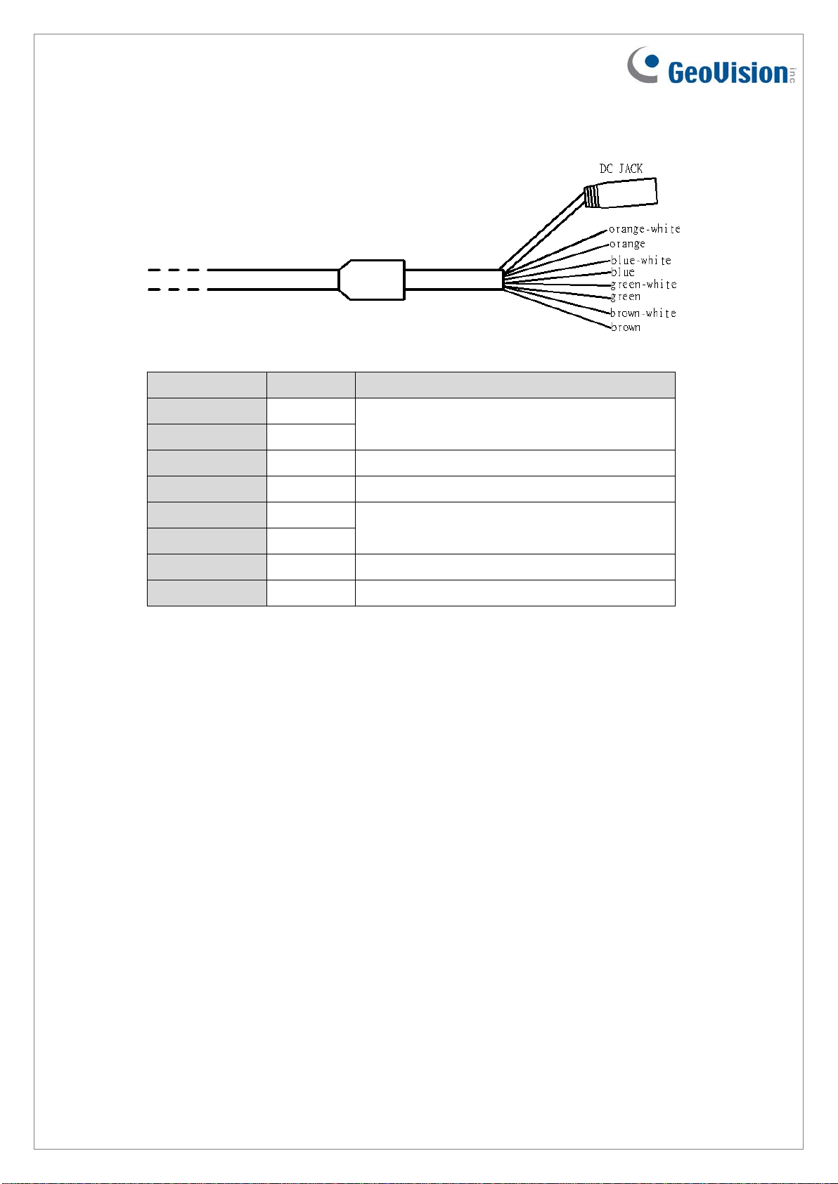
Wire Color
Definition
Function
Orange-White
D485+
Orange
D485-
Blue-White
GND
GND
Blue
GND
GND
Green-White
DATA 1
Green
DATA 0
Brown-White
DI
External control signal input, H:3.3V / L:0V
Brown
DO
Not functional
Output Cable Descripti ons
Not functional
Wiegand communication interface
Figure-1
1. Wiegand Communication Interface
1.1. Connect with access controller using Wiegand interface (one-way operation).
1.2. Support by Wiegand 64 interface.
2. DI (external control signal input)
2.1. Signal level defining: High level (H) : 3.3V / Low level (L) : 0V (GND signal)
2.2. When the external control signal input is at high level and the GV-RU9003 is in the
standby mode, the GV-RU9003 will not output any identification code to the backend access controller.
2.3. When the external control signal input is at low level and the GV-RU9003 is in the
working mode, the GV-RU9003 will output the identification code on the tag to the
back-end access controller.
2.4. If DI is not in use, connect it with the blue or blue-white wire.
December 14, 2016
Page 3
3
Recommended Installation of GV-RU9003 RFID Reader
1. Secure the GV-RU9003 RFID reader on a column, pedestal, wall, or beam at a height
between 1.8 - 2.2 m (5.9 – 7.2 ft) above the ground. Be sure to leave some space to
adjust the reader’s a ngle to the upper, lower, left, or right position.
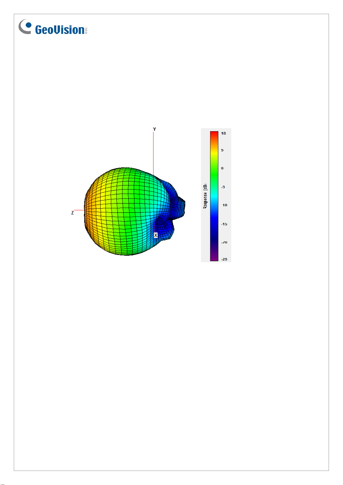
2. Check the antenna pattern as listed below and make sure that the tags on the passing
vehicles will be on the opposite side of the reader.
Figure-2
3. Although the ideal sensing range of GV-RU9003 is within 10 m (32.8 ft), the actual
sensing range varies due to weather (raining, fog, sunny) and installation method
(horizontal, inclining).
December 14, 2016
Page 4

4
DC Jack
DC Jack Power Cable
Input Voltage 9 ~15 V
GV-RU9003
Controller
Connection of GV-RU9003 RFID Re ader
1. Connect the GV-RU9003 to a Wiegand signal source based on the communication
interface of the access controller.
Figure-3
2. DI (brown-white) is the input signal (e.g. ground induction loop or photo interrupter)
controlling the operating mode of the GV-RU9003 with external control. If external
control is not in use, please connect it with the blue or blue/white wire.
3. Connect the GV-RU9003 to power using one of the methods:
Connect the DC Jack to a power adaptor (self-prepared) as shown in Figure 3.
Connect the DC Jack to the controller using the DC Jack power cable (supplied) as
shown in Figure 4.
Figure-4
December 14, 2016
Page 5

5
L-bracket
Screws x 4
Installing GV-RU9003
You can install the reader on a pole or a pillar. Two types of pole mounts are recommended,
as indicated below.
Note: Make sure the diameter of the pole is within 53 mm (0.17 ft).
1. Secure the L-bracket with four screws (supplied) on the rear sid e of the UHF RFID
Reader.
December 14, 2016
Page 6

6
Fixed-clamp
U-clip
Hexagon screw nuts
Adjust the angle
2. Secure the reader on a pillar or a pole using fixed-clamp and U-clip.
3. Adjust the angle of the U-clip on L-bracket and secure the hexagon screw nuts.
December 14, 2016
Page 7

7
4. Overview of pole m ount.
December 14, 2016
Page 8

8
GV-RU9003
Input voltage
9 ~15 V
Antenna gain
7.71 dBi (circular polarization)
Antenna receiving
50 ohm U.FL.
Wiegand interface
Wiegand 64 bit
RU9003 EU 865-868 MHz
Emission power
27.9 dBm
Modulation scheme
PR-ASK, ASK
Current
<1A max.
Protocol
EPC Gen2 (ISO 18000-6C)
Receiving sensitivity
-85 dBm
Sensing range
10 m (32.8 ft) max.
Water resistance
IP56
Operating temperature
-20°C ~ 55 °C / -7.6°F ~ 131°F
Storage temperature
-20°C ~ 85°C / -7.6°F ~ 185°F
LEDs
Red, Green
Humidity
5-90 %
Dimensions
228 x 228 x 52.3 mm / 8.97 x 8.97 x 2.04 in
Weight
530 g / 1.16 lb
Certification
NCC, FCC, CE
Specification
Operating frequency RU9003 TW 922-928 MHz
RU9003 US 902-928 MHz
Note:
1. The GV-ASManager V4.4.2.0 is required.
2. Wiegand interface supports both GeoVision AS2xxx/4xxx/8xxx controllers and 3rd party
controllers (Wiegand 64 Bits).
3. Specifications are subject to change without notice.
December 14, 2016
 Loading...