

Page 1
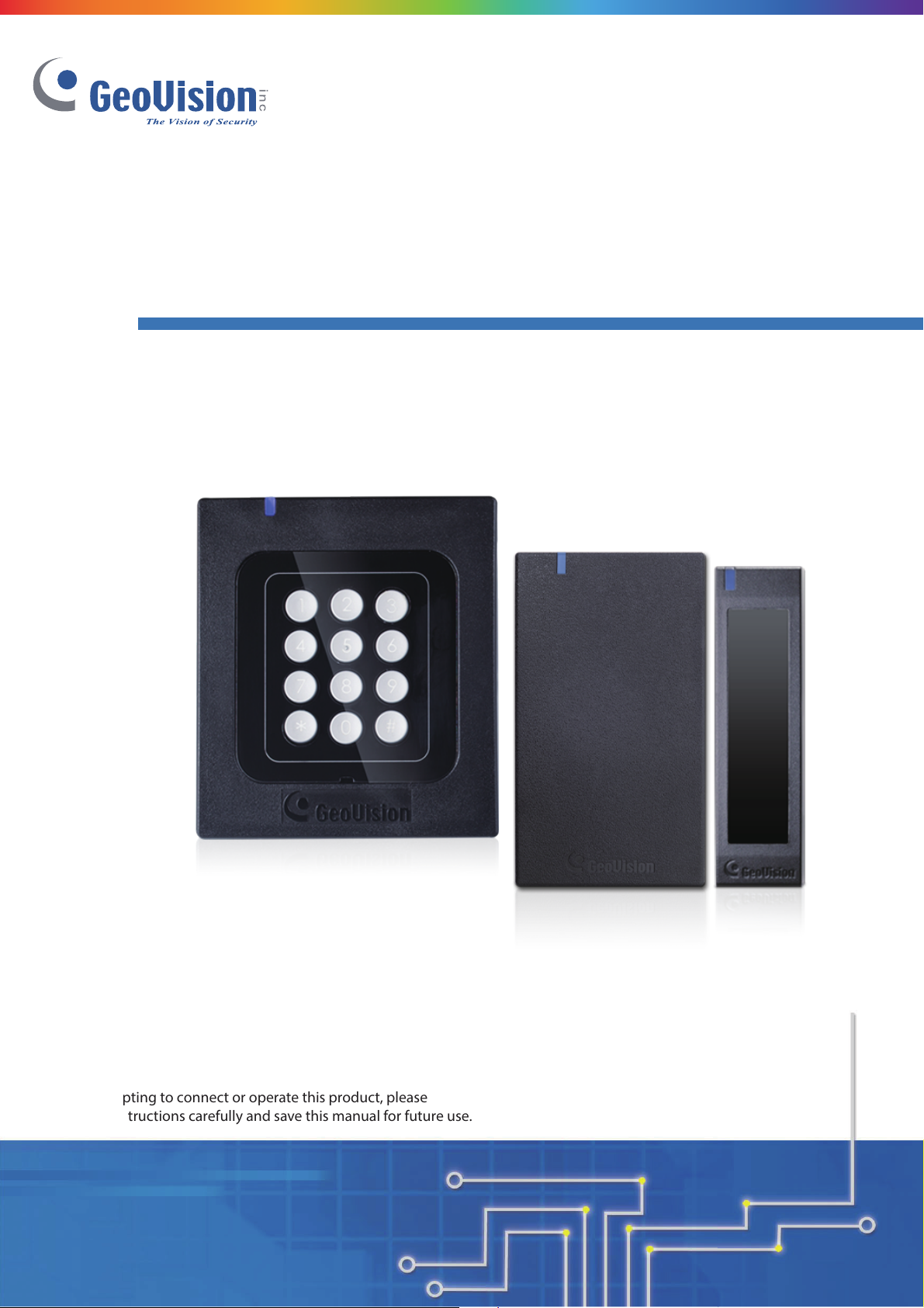
GV-RK1352 / R1352 / DFR1352 Reader
Installation Guide
Before attempting to connect or operate this product, please
read these instructions carefully and save this manual for future use.
R K.R. DF R1352-UL-B
Page 2

© 2016 GeoVision, Inc. All rights reserved.
Under the copyright laws, this manual may not be copied, in whole or in part,
without the written consent of GeoVision.
Every effort has been made to ensure that the information in this manual is
accurate. GeoVision, Inc. makes no expressed or implied warranty of any kind
and assumes no responsibility for errors or omissions. No liability is assumed
for incidental or consequential damages arising from the use of the information
or products contained herein. Features and specifications are subject to
change without notice.
Note: No memory card slot or local storage function for Argentina.
GeoVision, Inc.
9F, No. 246, Sec. 1, Neihu Rd.,
Neihu District, Taipei, Taiwan
Tel: +886-2-8797-8377
Fax: +886-2-8797-8335
http://www.geovision.com.tw
Trademarks used in this manual: GeoVision, the GeoVision logo and GV
series products are trademarks of GeoVision, Inc. Windows and Windows XP
are registered trademarks of Microsoft Corporation.
June 2016
Page 3

Contents
GV-RK1352 / R1352 / DFR1352 Card Reader.......................................1
1. Physical Descriptions...................................................................... 3
1.1 Electric Wire…………………………………………………………………………....3
1.2 Keypad (GV-RK1352 Only) ………………………………………………………….5
1.3 LED Indicator and Beeper…………………………………………………………....5
2. Connecting the Reader to GV-AS Controller..................................6
2.1 Connecting through Wiegand Interface…………………………………………….7
2.2 Connecting through RS-485 Interface……………………………………………...7
2.2.1 Defining Readers on GV-AS Controller Web Interface…………………………9
3. Installing the GV-R/RK/DFR Config AP.........................................11
4. Overlaying Card Numbers on GV-System Live View................... 12
4.1 Defining the ID Number and Setting the Reader to Slave……………………...12
4.2 Adding the Reader to GV-System…………………………………………………14
5. Changing the Default Settings of Beeper and LED......................15
5.1 Setting up Beeper and LED on GV-R/RK/DFR Config AP……………………...15
5.2 Wiring the Beeper and LED to the GV-AS Controller…………………………....17
5.3 Configuring the Beeper and LED Settings for Each Door/Gate………………..18
6. Setting UID or GID on GV-R/RK/DFR Config AP .......................... 19
7. Firmware Upgrade..........................................................................21
8. Specifications.................................................................................22
9. Mounting Method for the Readers ................................................ 23
9.1 Standard Mount for the Readers…………………………………………………...23
9.2 Optional Mount for GV-RK1352 Card Reader…………………………………….25
Page 4

GV-RK1352 / R1352 / DFR1352 Card Reader
The content of this installation guide refers to the following readers:
• GV-RK1352 firmware V1.2
• GV-R1352 firmware V1.2
• GV-DFR1352 (Rev. B) firmware V1.2
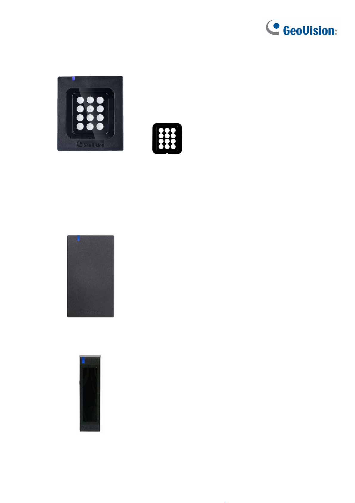
Introduction
GV-RK1352 / R1352 / DFR1352 are card readers capable of recognizing identification cards.
GV-RK1352 comes with keypad, allowing it to also recognize PIN codes. GV-DFR1352 is
designed to be installed on the door frame.
Featured with the Wiegand and RS-485 outputs, the readers can be connected to GV-AS
series control panel. The readers are protected by a weather sealed and IP66 compliant
housing for outdoor use.
1
Page 5
Packing List
GV-RK1352
1. GV-RK1352 Card Reader
2. Screw x 2
3. Screw Anchor x 2
4. Front Cover Plate x 1
GV-R1352
5. Software CD
6. Warranty Card
7. Installation Guide
8. Connection plug with the stand-alone power
adapter (Optional)
1. GV-R1352 Card Reader
2. Screw x 3
3. Screw Anchor x 2
4. Security Torx
5. Software CD
6. Warranty Card
7. Installation Guide
8. Connection plug with the stand-alone power
GV-DFR1352
adapter (Optional)
1. GV-DFR1352 Card Reader
2. Screw x 2
3. Screw Anchor x 2
4. Front Cover Plate x 2
5. Software CD
6. Warranty Card
7. Installation Guide
8. Connection plug with the stand-alone power
adapter (Optional)
2
Page 6

1. Physical Descriptions
1.1 Electric Wire
GV-RK1352
Wire Color Function
Red DC 7.5 ~ 12 V
Black GND
Yellow Beeper
Orange Green LED
Light Red Red LED
Green Wiegand Data 0
White Wiegand Data 1
Blue RS-485 +
Light Blue RS-485 -
Rear View
GV-R1352
Wire Color Function
Red DC 7.5 ~ 12V
Black GND
Yellow Beeper
Orange Green LED
Light Red Red LED
Green Wiegand Data 0
White Wiegand Data 1
Blue RS-485 +
Light Blue RS-485 -
Gray N/A
Purple N/A
Brown N/A
Rear View
3
Page 7

GV-DFR1352
Wire Color Function
Red DC 7.5 ~ 12V
Black GND
Yellow Beeper
Orange Green LED
Light Red Red LED
Green Wiegand Data 0
White Wiegand Data 1
Blue RS-485 +
Light Blue RS-485 -
Gray N/A
Purple N/A
Brown N/A
Rear View
Install the GV-DFR1352 to the door frame using the supplied screws and screw anchors.
Before placing and sticking the front cover plate to the GV-DFR1352, remove the Plastic
Cover to prevent scratches to the cover after installed.
4
Page 8

1.2 Keypad (GV-RK1352 Only)
When accessing an entry using GV-RK1352, you can enter the door’s PIN code on the
keypad or present the card and then enter the card’s PIN code on the keypad to be granted
access. The access mode is defined on GV-ASManager.
1. 0~9 Number Keys: Press the number keys to enter the PIN code.
2. # Key: Press the # key to confirm the PIN code.
3. ﹡Key: Press the ﹡key to cancel the PIN code.
1.3 LED Indicator and Beeper
In standby mode, the LED is blue. When a card is read, the LED flashes green and the
beeper beeps once.
The reader comes with external control wires for Green LED, Red LED and Beeper. You can
connect these control wires to GV-AS4111 Kit / 8111 Kit to change the default settings of the
LED and Beeper. For details on how to configure the settings, refer to 5. Changing the
Settings of Beeper and LED later in this installation guide.
5
Page 9

2. Connecting the Reader to GV-AS Controller
You can connect the readers to GV-AS Controllers through Wiegand or RS-485 interface.
Note that the connection between the reader and GV-AS Controller varies with different
controller models. To see how many readers can be connected to a GV-AS Controller, refer
to The Number of Readers Supported by GV-AS Controllers table at the end of this
installation guide.
Note:
1. GV-RK1352 / R1352 / DFR1352 is compatible with GV-AS Controllers. However, to
enable the keypad function on GV-RK1352, you can only connect GV-RK1352 to the
controllers through Wiegand or RS-485 interface
2. Each GV-RK1352 / R1352 / DFR1352 consumes 60 mA of power. The total power
consumption of the output devices and readers connected to the GV-AS Controller
must be under 3.5A for GV-AS4111 Kit or 5A for GV-AS8111 Kit. Connect an external
power supply if the power supplied from GV-AS Controller is insufficient.
3. Connecting method of external power supply is as below:
a. Plug in the ferrous type cord to the external power supply.
b. Connect ferrous type cord to the card reader. (The wiring methods shall be in
accordance with the National Electrical Code, ANSI/NFPA 70.)
6
Page 10

2.1 Connecting through Wiegand Interface
The following diagrams show the connection between GV-RK1352 and GV-AS8111 Kit /
4111 Kit. Up to eight readers can be connected to GV-AS8111 Kit / 4111 Kit through the
controller’s Wiegand interface.
GND
D1
D0
Wiegand A
12V
GV-AS8111 Kit / 4111 Kit
(Black)
(White)
(Green)
(Red)
GV-RK1352 or
Wire Color Function
Black GND
White Wiegand Data 1
Green Wiegand Data 0
Red DC 7.5 ~ 12V
GV-R1352
2.2 Connecting through RS-485 Interface
The following diagrams show the connection between GV-RK1352 and GV-AS8111 Kit /
4111 Kit. Up to eight readers can be connected together to the RS-485 interface on GV-
AS8111 Kit / 4111 Kit..
z Connecting four or less readers to GV-AS8111 Kit / 4111 Kit.:
Wire Color Function
Black GND
Light Blue RS-485 -
Blue RS-485 +
Red DC 7.5 ~ 12V
GND
B-
B+
A-
RS485
A+
12V
GV-AS8111 Kit / 4111 Kit
(Black)
(Light Blue)
(Blue)
(Red)
GV-RK1352 or GV-R1352
Read er 1
Read er 4
z Connecting five or more readers to GV-AS8111 Kit / 4111 Kit:
For readers five to eight, connect the RS-485 cable to the RS-485 interface on GV-
AS8111 Kit / 4111 Kit and then connect the 12V power output and GND of the reader to
a 12V DC power output on the controller.
7
Page 11

GND
12V
GND
12V
GND
12V OU TPUT
12V
(Red)
(Black)
RS485
GND
B-
B+
A-
A+
12V
(Black)
(Light Blue)
(Blue)
(Red)
Readers 1-4 Read er s 5-8
GV-AS8111 Kit / 4111 Kit
GV-RK1352 or GV-R1352
Note:
1. For RS-485 connection between GV-AS Controllers and readers, use additional
power for the readers when the distance ranges from 30.48 meters ~ 600 meters (100
ft ~ 1968.50 ft). There is no need to use additional power when the distance is within
30.48 meters (100 ft).
2. Recommended power supply:
Manufacturer Model Output rating
Powertron PA1015-2I
12V, 1.25A, 15W Max
8
Page 12

2.2.1 Defining Readers on GV-AS Controller Web Interface
Since multiple readers can connect to GV-AS Controller using one RS-485 interface, you
need to specify which door each reader controls. This section explains how to define readers
on the Web interface of GV-AS Controller. On the Web interface, you can also set the reader
to read the GID or UID on GV-AS ID Cards / Key Fobs. Note that the Web interface of
different GV-AS Controller models varies.
1. On the controller’s Web interface, click Extended Reader. This dialog box appears.
2. In the GV-Reader/CR420/GF1921/GF1922 section, select the RS485 checkbox in front of
the ID number and type the Serial Number on the rear panel of the reader. The ID
number will be assigned to the reader.
3. Select a door/gate for the reader from the Function drop-down list.
4. Next to Read Mode, select Read UID or Read GID to set the connected readers to read
UID (unique identifier) or GID (GeoVision ID) on GV-AS ID Cards / Key Fobs.
9
Page 13

If you select Read GID, make sure there are two numbers on your GV-AS ID Cards / Key
Fobs as shown below. If there is only one number on your GV-AS ID Cards / Key Fobs,
GID is not supported, and you must select Unique Identification (UID).
5. Click Submit.
Note:
1. When you click Submit on the Extended Reader page of a GV-AS8111 Kit / 4111 Kit,
all readers connected through RS-485 interface will reboot.
2. GID ID format is only supported in GV-RK1352 / GV-R1352 / GV-DFR1352 (Rev. B)
V1.2 or later.
3. If you are using third-party cards or key fobs, you must set the reader to read UID.
10
Page 14

3. Installing the GV-R/RK/DFR Config AP
The GV-R/RK/DFR Config AP allows you to set the reader’s beeper / LED, ID number,
master / slave status, and whether it reads UID or GID. When using the Config AP, the
reader needs to be connected to a PC through GV-COM, GV-Hub or GV-NET/IO Card V3.1.
RS-485
(Blue) RS-485 +
(Light Blue) RS-485 -
GV-RK1352
You can install the Config AP from the Software DVD or GeoVision Website. To use a GV-
COM, GV-Hub or GV-NET/IO Card V3.1, you also need to install GeoVision USB Device
Driver.
Installing from Software CD
1. Insert the software CD and the Install Program window will pop up automatically.
2. Select Install GeoVision USB Device Driver.
3. In the GeoVision USB Driver Installer window that appears, select Install.
4. Go back to the Install Program window, and select Run GV-Reader Config Utility.
GV-HUB / GV-COM /
GV-NET/IO Card
RS-232
USB
PC
Downloading from GeoVision Website
1. Go to the Software Download and Upgrading page of GeoVision Website:
http://www.geovision.com.tw/english/5_8_AS.asp
2. Select GV-Reader from the drop-down list, and click the Download icon
GV-RK1352 & GV-R1352 & GV-DFR1352 Config Utility.
3. Select Driver from the drop-down list and click the Download icon of GV-
USB Device Driver.
of
11
 Loading...