

Page 1
GV-Reader 1251 and 1352 V2
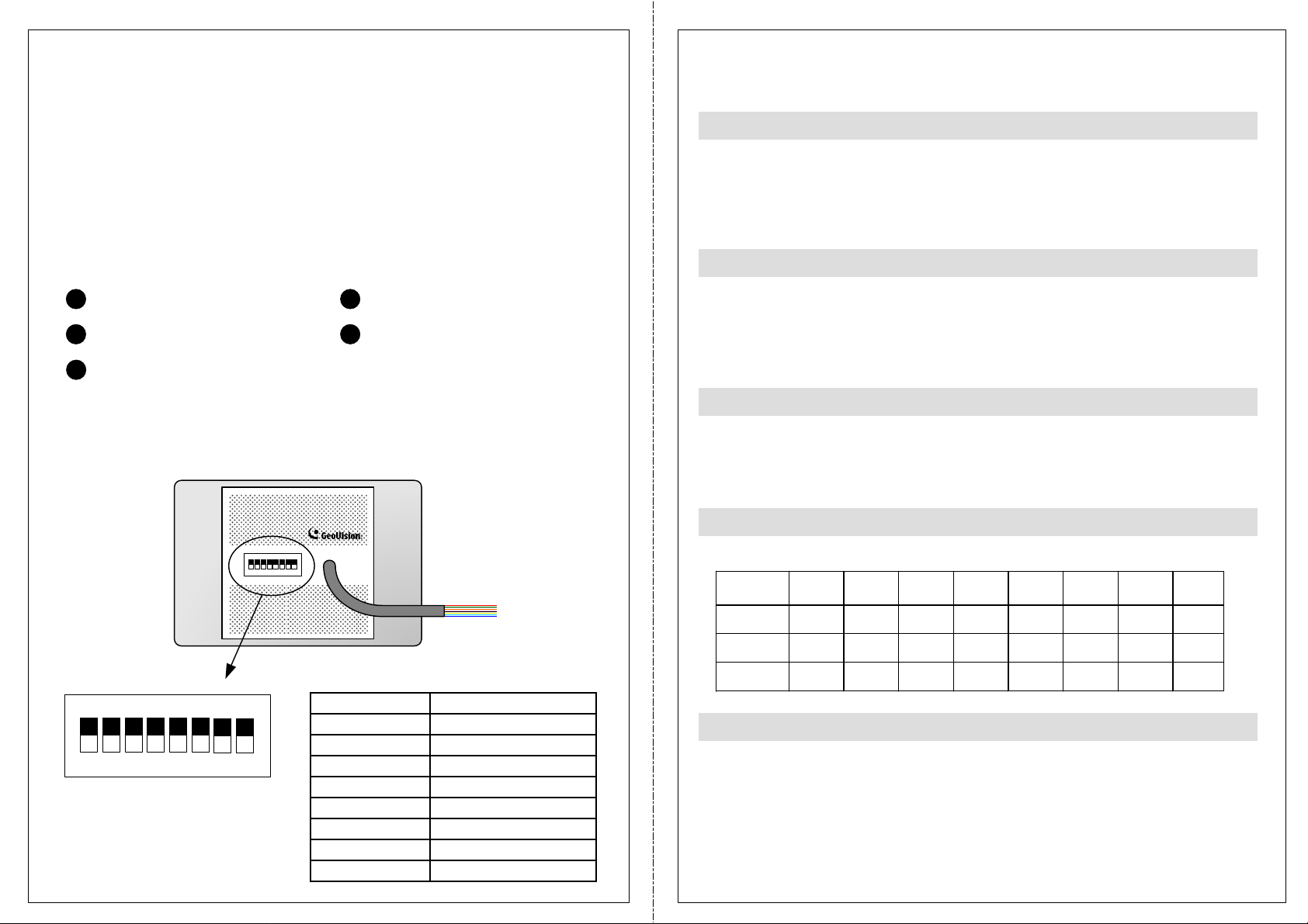
Switch Setting
Default settings are all ON.
The GV-Reader includes transmit-receive antenna and electronics. It has both
Wiegand and RS-485 outputs that can be connected to any standard access
control panel. The GV-Reader has a bi-color LED indicator, which is
controllable by the host system and changes from red to green to indicate
access granted. The GV-Reader also has a host-controllable buzzer.
Packing List
1
GV-Reader
2
Bag of screws
3
GV-Reader Software CD
4
GV-Reader Installation Guide
5
Warranty Card
Overview
ON
1 2 3 4 5 6
ECE
7 8
Electric Wire
SW 1 Beeper Control
The default mode for the Beeper Control is the internal control. When the setting
is “On”, the Reader is sounded after a card is read. When the setting is “Off”, the
Beeper is controlled externally. You can use the external beeper control line to
activate the beeper.
SW2-SW3 Green/Red LED Control
The default mode for the Green/Red LED Control is the internal control. The
LED is normally red. When a card is read, the LED flashes green. When the
setting is “Off”, the Green/Red LED is controlled externally. The external control
lines can then be used to operate the LEDs.
SW4 Master/Slave
The switch is used to select the Reader’s communication interface. When the
setting is “On”, the Reader is controlled by Wiegand signal. When the setting is
“Off”, the Reader is for RS-485 signal.
SW5-SW7 ID Setting
Switch 5 to switch 7 is used to set the Reader’s ID during a chain connection.
ID 0 1 2 3 4 5 6 7
Switch
ON
1 2 3 4 5 6
ECE
7 8
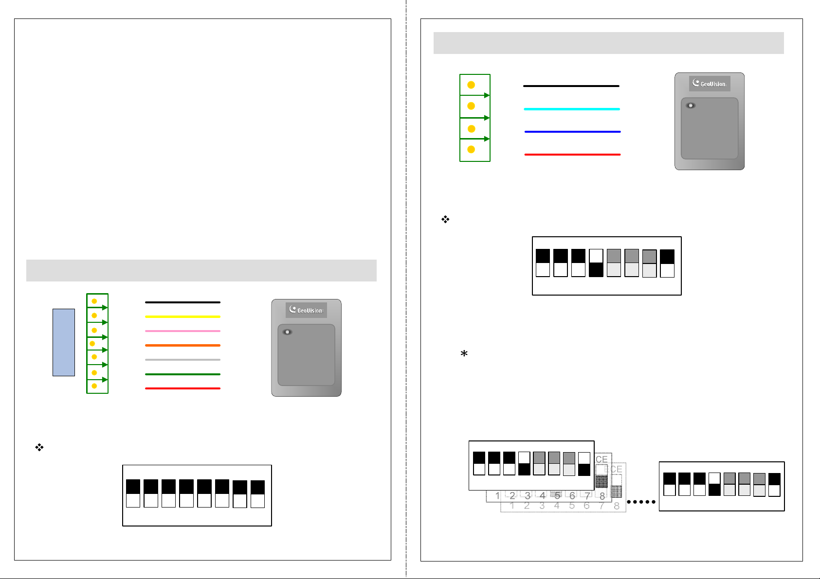
Electric Wire
Red 7.5 ~ 12 V DC
Black GND
Green Wiegand Data0
White Wiegand Data1
Blue RS-485 +
Light Blue RS-485 -
Yellow Beeper
Orange Green LED
L
ight Red Red LED
SW5 OFF OFF OFF OFF ON ON ON ON
SW6 OFF OFF ON ON OFF OFF ON ON
SW7 OFF ON OFF ON OFF ON OFF ON
SW8 RS-485 Terminal Resistor
When the setting is “On,” a 120-ohm resistor is connected between RS-485+
and RS-485-. This setting is used in the last device when multiple RS-485
devices are connected together.
NOTE: After changing the dip switch settings, the unit must be reset by
powering down then up again before the new switch setting will take effect.
Page 2
Wiring Connection
The GV-Reader is compatible with any standard access controllers. The
following diagrams illustrate how to connect the GV-Reader to GV-AS Controller
through Wiegand interface or RS-485 interface, and how to connect the GVReader to third-party access controllers and GV-System.
After you wire the connection between the GV-Reader and the access controller,
ensure the related switch setting on the GV-Reader is configured correctly.
Connecting to GV-AS Controller through RS-485 Interface
GND
-
+
12V
(Black)
(Light blue)
GV-Reader
(Blue)
(Red)
Note: Each reader consumes 60 mA of power. The total power consumption of
the output devices and readers connected to the GV-AS Controller must be
under 3A (for GV-AS210 / 2110), 3.5A (for GV-AS410 / 4110) or 5A (for GVAS810 / 8110). Connect an external power supply if the power supplied from GVAS Controller is insufficient.
Connecting to GV-AS Controller through Wiegand Interface
GND
BZ
RL
GL
Wiegand
GV-AS Controller
D1
D0
12V
(Black)
(Yellow)
(Light red)
(Orange)
(White)
(Green)
(Red)
GV-Reader
GV-Reader
Switch Setting for Wiegand Connection
GV-AS Controller
GV-Reader
Switch Setting for RS-485 Connection
ON
1 2 3 4 5 6
SW4 must be turned OFF.
Switch Setting for Connecting Multiple GV-Readers (RS-485)
Multiple GV-Readers can be connected to the GV-AS Controller
through a single RS-485 cable. When you connect more than one GVReader to the GV-AS Controller, on the last connected GV-Reader
turn SW8 to ON.
ON
ECE
ECE
7 8
ON
1 2 3 4 5 6
SW4 must be turned ON.
ECE
7 8
1 2 3 4 5 6
GV-Reader 1 GV-Reader 8
7 8
ON
1 2 3 4 5 6
ECE
7 8
Page 3

Defining Readers on GV-AS Controller Web Interface
After configuring the switch settings, you need to define the readers’ ID
number and specify which door each reader controls on the Web interface
of the GV-AS Controller.
Connecting to GV-System and Third-Party Access Controllers
GV-Reader is also compatible with third-party access controllers. With its
compatibility, you can also add a GV-System to this connection to empower
your management.
1. Type the GV-AS Controller’s IP address in the Web browser.
2. Type the username and password to login.
3. In the left menu, click Extended Reader. This page appears.
After connecting the GV-Reader to the access controller through the Wiegand
interface, connect the GV-Reader to the GV-System via GV-COM, GV-Hub or
GV-NET/IO Card V3.1.
Note: The GV-Reader is not compatible with the GV-NET Card and the GVNET/IO Card of versions earlier than V3.
(Red)
Access Controller
(third-party)
(power supply: 7.5~12 V)
(Black)
(Green)
(White)
GV-Reader
GV-Reader
GV-System
(Blue) +
(Light blue) -
GV-COM / GV-Hub /
GV-NET/IO Card V3.1
USB
4. Select the RS485 checkbox in front of the ID number.
The ID number must match the ID you configured using SW5 – SW7.
5. Leave the serial number field blank.
6. Select a door/gate for the reader under Function. Click Submit.
Switch Setting
ON
1 2 3 4 5 6
ECE
7 8
SW4 must be turned OFF.
Page 4

Specifications
The number of GV-Reader 1251 supported by GV-AS Controllers
CPU 8-bit microprocessor
Wiegand Interface Wiegand 26 - 40 bits, distance 30 m / 100 ft
Power Source DC 7.5 ~ 12 V
Power Consumption 60 mA
LED Red, Green LED
Beeper Buzzer
Frequency
GV-Reader 1251 (V1)
GV-Reader 1352 (V2)
RS-485 9600 bps
Color Black
Operation Temperature
Operating Humidity 10 ~ 90% RH (non-condensing)
Dimensions (W x H x D)
Weight 150 g / 0.33 lb
Ingress Protection IP54
Certification CE, FCC, RoHS
125 KHz (Proximity EM Card)
13.56 MHz for ISO14443A (Mifare Class)
-35 ~ 65°C / -31 ~ 149°F
75 x 115 x 15 mm, with enclosure 35 (D) mm
3 x 4.5 x 0.6 in, with enclosure 1.38 (D) in
GV-AS Controller Model
GV-Reader 1251 Interface
Wiegand RS-485
Not supported Not supportedGV-AS100
Not supported Not supportedGV-AS110 / 120
Not supported Not supportedGV-AS1010
Not supported Not supportedGV-AS1110
Not supported Not supportedGV-AS100 / 110 / 120 with GV-ASBox
Not supported Not supportedGV-AS100 / 110 / 120 with GV-ASNet
4 8GV-AS210 / 2110
8 8GV-AS410 / 4110
8 16GV-AS810 / 8110
Not supported 2GV-EV48
The number of GV-Reader 1352 V2 supported by GV-AS Controllers
GV-Reader 1352 V2 Interface
GV-AS Controller Model
Wiegand RS-485
1 1GV-AS100
1 Not supportedGV-AS110 / 120
Not supported 2GV-AS1010
Not supported Not supportedGV-AS1110
2 4GV-AS100 / 110 / 120 with GV-ASBox
Not supported 2GV-AS100 / 110 / 120 with GV-ASNet
4 8GV-AS210 / 2110
8 8GV-AS410 / 4110
8 16GV-AS810 / 8110
Not supported 2GV-EV48
 Loading...