

Page 1

GV-IP Speed Dome Quick Start Guide
Bet a V ersion
Date: 2020/04/29
This documen t is a beta version of a hardware produc t that may be
changed substantially prior to final commercial release. This
document is provided for inf orma tio nal pu rposes only and
GeoVision Inc. makes no warranties, either express or implied, in
this document. Information in this do cume nt is su bje ct to cha ng e
without notice.
Page 2

Contents
Note for Connecting to GV-VMS / DVR / NVR .................................................. ii
Note for Recording............................................................................................. ii
1. Introduction........................................................................................................ 1
1.1 Packing List ............................................................................................... 1
1.2 Overview of GV-QSD5730 ......................................................................... 3
1.3 Overview of GV-QSD5731-IR .................................................................... 4
2. Installation.......................................................................................................... 5
2.1 Installing GV-QSD5730.............................................................................. 5
2.2 Installing GV-QSD5731-IR......................................................................... 7
3. Connecting the Camera..................................................................................... 8
3.1 Power Connection..................................................................................... 8
3.2 Audio / Alarm I/O & RS-485 Connection .................................................. 9
4. Accessing the Camera..................................................................................... 10
4.1 System Requirements............................................................................. 10
4.2 Looking Up the Dynamic IP Address......................................................11
4.3 Configuring the IP Address .................................................................... 12
5. The Web Interface ............................................................................................ 13
5.1 Viewing Live View Video......................................................................... 13
5.2 PTZ Functions.......................................................................................... 15
6. Upgrading System Firmware .......................................................................... 16
7. Restoring to Factory Default........................................................................... 17
7.1 Using the Web Interface00...................................................................... 17
7.2 Directly on the Camera ........................................................................... 17
i
Page 3

Note for Connecting to GV-VMS / DVR / NVR
The GV-IP Speed Dome is designed to work with GV-VMS / DVR / NVR, a video management
system. Note the following when the camera is connected to GV-VMS / DVR / NVR:
Once the camera is connected to the GV-VMS / DVR / NVR, the resolution set on the
GV-VMS / DVR / NVR will override the resolution set on the camera’s Web interface. You can
only change the resolution settings through the Web interface when the connection to the
GV-VMS / DVR / NVR is interrupted.
Note for Recording
Mind the following when using a memory card for recording:
Recorded data on the memory card can be damaged or lost if the data are accessed
while the camera is under physical shock, power interruption, memory card detachment
or when the memory card reaches the end of its lifespan. No guarantee is provided for
such causes.
The stored data can be lost if the memory card is not accessed for a long period of time.
Back up your data periodically if you seldom access the memory card.
Memory cards are expendable and their durability varies according to the conditions of
the installed site and how they are used. Back up your data regularly and replace the
memory card annually.
To avoid power outage, it is highly recommended to apply a battery backup (UPS).
For better performance, it is highly recommended to use Micro SD card of MLC NAND
flash, Class 10.
Replace the memory card when its read/write speed is lower than 6 MB/s or when the
memory card is frequently undetected by the camera.
ii
Page 4
Introduction
1
1. Introduction
Welcome to the GV-IP Speed Dome Quick Start Guide. In the following sections, you will learn
the basic installations and configurations. For a detailed user manual, see the GV-IP Speed
Dome User’s Manual.
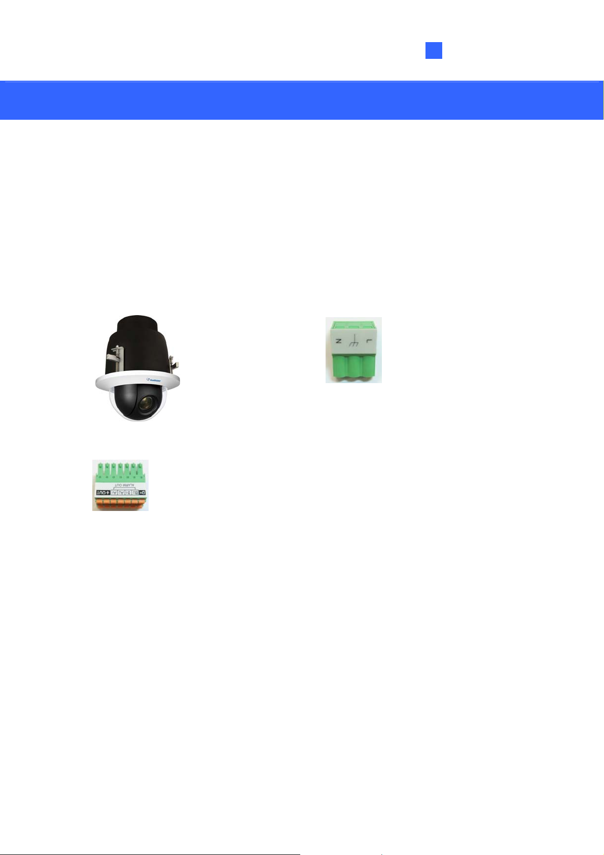
1.1 Packing List
GV-QSD5730
GV-QSD5730
14-Pin Alarm/Audio I/O Terminal Block
3-Pin Power Terminal Block
Drill Template Paster
Download Guide
Warranty Card
1
Page 5
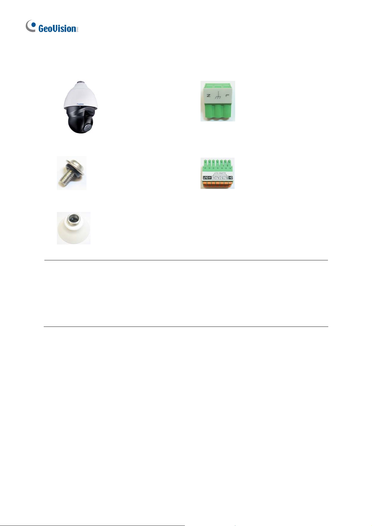
GV-QSD5731-IR
GV-QSD5731-IR
M4 Screw with Rubber
Pendant cap
3-Pin Power Terminal Block
14-Pin Alarm/Audio I/O Terminal Block
Download Guide
Warranty Card
Note:
1. It is required to purchase GV-Mount104-1 / 105-1 / 210-1 / 208-4 to mount
GV-QSD5731-IR to a wall, ceiling or pole.
2. PoE function is available for GV-QSD5731-IR only when a GV-PA902BT Gigabit PoE
Adapter is purchased for connection.
2
Page 6
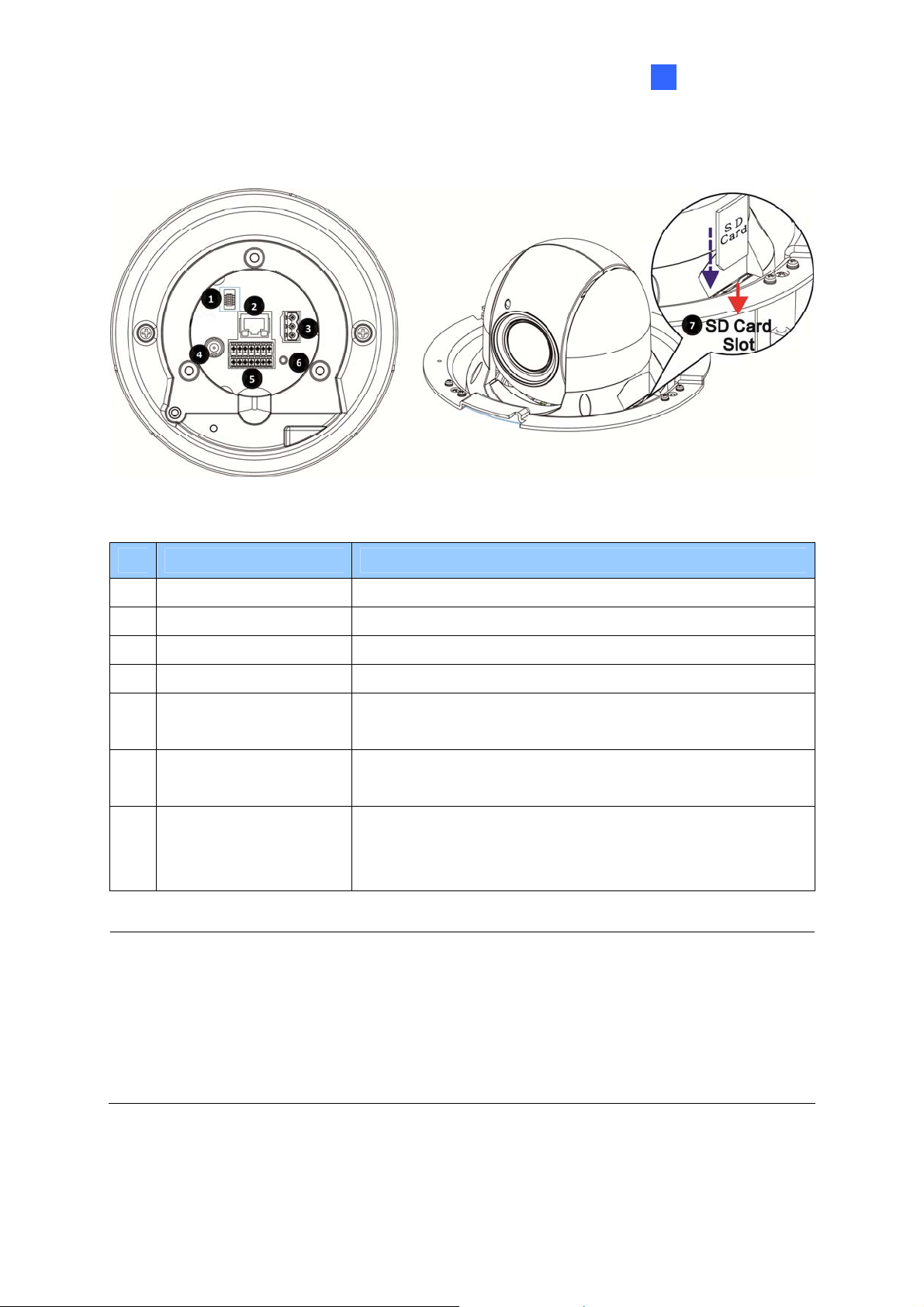
1.2 Overview of GV-QSD5730
Introduction
1
No. Name Function
1.
2.
3.
4.
5.
6.
7.
Note:
Console Connector
RJ-45 Port
Power Connector
BNC
Audio/Alarm I/O
& RS-485 Connector*
Default Button
SD Card Slot
N/A
For network and PoE connection
AC 24V power connection
For analog video output
Audio/Alarm I/O & RS-485 connection
Press the button with a proper tool for at least 20 seconds
to restore the system.
Open the dome cover and insert the SD card into the card
slot to store videos and snapshots. Do not remove the SD
card when the camera is powered on.
1. Do NOT connect external power supply to the I/O connector of the camera.
2. It is not recommended to record with the SD card for 24/7 continuously, as it may not
be able to support long term continuous data read/write.
3. The Audio In port only supports microphones with power supply.
3
Page 7

1.3 Overview of GV-QSD5731-IR
No. Name Function
RJ-45 Port
1.
Power Connector
2.
Default Button
3.
Audio/Alarm I/O &
4.
RS-485 Connector
BNC
5.
SD Card Slot
6.
Note:
1. Do NOT connect external power supply to the I/O connector of the camera.
For network and PoE connection
AC 24V power connection
Press the button with a proper tool for at least 20 seconds
to restore the system.
Audio/Alarm I/O & RS-485 connection
For analog video output
Open the dome cover and insert the SD card into the card
slot to store videos and snapshots. Do not remove the SD
card when the camera is powered on.
2. It is not recommended to record with the SD card for 24/7 continuously, as it may not
be able to support long term continuous data read/write.
3. The Audio In port only supports microphones with power supply.
4
Page 8

Installation
2
2. Installation
In the following sections, you will learn how to install GV-QSD5730 to the ceiling with standard
packages and how to install GV-QSD5731-IR with optional GV-Mount accessories.
2.1 Installing GV-QSD5730
Required Items
Tool fo r dr illing a hole on the ceiling (user-prepared)
M4 Crosshead Screw Driver (user-prepared)
SD card (user-prepared)
1. Determine a ceiling location for camera installation. Stick the drill template paster to the
ceiling, and then drill a hole of radius 192 mm according to the drill template.
Remove the dome cover by turning the dome cover counter-clockwise and insert the SD
2.
card.
5
Page 9

3. Thread the Ethernet, power, and/or I/O cables through the ceiling opening.
4. Connect the Ethernet, power, and/or I/O cables to the camera. Align and put the camera to
the ceiling opening.
5. Extend the ceiling clamps and clamp the camera to the ceiling by fastening the three
screws clockwise.
Secure the dome cover of the camera by turning the dome cover clock wise.
6.
6
Page 10

Installation
2
2.2 Installing GV-QSD5731-IR
Required Items
GV-Mount104-1 / GV-Mount105-1 / GV-Mount210-1 / GV-Mount208-4
(user-purchased)
M4 Crosshead Screw Driver (user-prepared)
SD card (user-prepared)
1. Remove the cover of the SD card slot on the side of the camera. Insert the SD card and
secure the cover.
2. Thread the Ethernet, power, and/or I/O cables through the GV-Mount of your choice
(GV-Mount104-1 / GV-Mount105-1 / GV-Mount210-1 / GV-Mount208-4).
3. Install the GV-Mount at the desired location.
4. Thread the Ethernet, power, and/or I/O cables through the supplied pendant cap.
5. Connect the Ethernet, power, and/or I/O cables to the camera.
6. Attach the pendant cap to the camera and rotate until it is locked into position. Make sure the
screw hole on the pendant cap aligns to one of the three screw holes on the base of the
camera.
7. Secure the supplied Rubber Screw through the aligned screw holes.
8. Attach the camera to the installed GV-Mount.
For details, see GV-Mount Accessories Installation Guide.
7
Page 11

3. Connecting the Camera
3.1 Power Connection
To power up the camera, choose one of the following options below.
Connect the AC 24V power adaptor to the power connector of the camera and the power
outlet. The pin definition of the power connector is as below:
Pin Definition
1 AC 24V L (White; Positive)
2 GND
3 AC 24V N (Black; Negative)
Connect one end of the Ethernet cable to the RJ-45 connector of the camera and the other
end to a GV-PoE Adapter or PoE switch. For GV-QSD5731-IR, GV-PA902BT is required to
apply the PoE function and the following is the illustration of how to connect the camera
and the PoE adapter together.
8
Page 12

3.2 Audio / Alarm I/O & RS-485 Connection
Pin definition for I/O and RS-485 connection is as below:
Connecting the Camera
3
Pin Definition
1
Audio Out
GND
2
(Audio I/O)
3
Alarm Out A1
4
Alarm Out A2
Pin Definition Pin Definition Pin Definition
Alarm Out B1
5
Alarm Out B2
6
RS-485 D+
7
RS-485 D-
8
Alarm In 4
9
Alarm In 3
10
Alarm In 2 Def
11
Alarm In 1 Dn Definition
12
13
14
GND (Alarm
I/O
& RS-485)
Audio In
9
Page 13

4. Accessing the Camera
4.1 System Requirements
Once installed, your camera is accessible over the network. Make sure your PC has good
network connection, and meet the following requirements:
Operating System Windows 7 or later
Minimum: 4 GB Memory
Recommended: 8 GB
Minimum: Intel Core i5-2430M, 2.4 GHz CPU
Recommended: Intel Core i7-870, 2.93 GHz
Web Browser Microsoft Internet Explorer 11.0 (recommended)
Chrome
Firefox
Safari
10
Page 14

Accessing the Camera
4
4.2 Looking Up the Dynamic IP Address
By default, when the camera is connected to LAN with a DHCP server, it is automatically
assigned with a dynamic IP address. Follow the steps below to look up its IP address and set
up a login password.
Note: The PC installed with GV-IP Device Utility must be under the same LAN as your
camera.
1. Download and install the GV-IP Device Utility program from the company w ebsite.
2. On the GV-IP Utility wi ndow, click the
the same LAN. Click the Name or Mac Address column to sort.
3. Find the camera with its Mac Address, click on its IP address and select Web Page.
4. The prompt to create new passwor d appear s in the Web browser.
button to search for the IP devices connected in
5. Type the desired password and click Save. The login page appears.
11
Page 15

6. Type the usernam e admin and your password. Click Login.
Note: By default, the Administ r ator’s username is admin and cannot be modified.
4.3 Configuring the IP Address
By default, GV-QSD5730 / GV-5731-IR, connected to LAN without a DHCP server, is
assigned with a static IP address of 192.168 .0.10. Follow the st eps below to assign a new IP
address to avoid IP conflict with other GeoVision devices.
1. Open your Web browser, and type the default IP address 192.168.0.10.
2. For the first-time user, you will be asked to create a new password.
3. Type the username admin and your password. Click Login.
4. Click System, select Network in the left menu and select Basic.
5. Select Use fixed IP address.
6. Type the IP address, subnet mask, and default gateway address. Make sure that the IP
address of the camera is unique in the network.
7. Click Save.
Note: See details in 2.2.3 Network, GV-IP Speed Dome User’s Manual.
12
Page 16

5
5. The Web Interface
5.1 Viewing Live View Video
Once you log in the Web interface, you will see the live view as shown below.
The Web Interface
4 5 6 7 8 9 10 11 12
1
3
2
No. Name Function
1 Zoom
Adjust the camera’s zoom.
2 Focus Adjust the camera’s focus.
3 Iris Adjust the brightness of the image.
4 Control Panel Show or hide the control panel.
5 Video Quality Show or hide the bitrate and compression of each stream.
6 Full Screen
7 Talk
Display in full screen mode.
Turn on
or off outward audio transmission.
8 Listen Turn on or off inward audio transmission.
9 Snapshot Click to save JPEG snapshots.
13
Page 17

10 Live View Pause Pause or restart video streaming.
11 Record Turn on or off video recording.
12 Manual Trigger Turn on or off the manual trigger.
Note: See details in 2.1.1 Function Items on Home Page, GV-IP Speed Dome User’s
Manual.
14
Page 18

5.2 PTZ Functions
You can access the PTZ functions by selecting PTZ.
1
2
3
4
5
6
7
8
9
The Web Interface
5
No. Item Function
1 Preset
Cruise Set cruise paths for camera touring.
2
Auto Pan
3
Sequence
4
Home Function
5
Select a preset and the camera goes to the selected preset.
Start or stop aut o panning of the camera.
Set viewing sequence of the camera.
Set operation modes for constant monitoring when the camera
remains idle a period of time.
Tilt Range
6
Set the minimum and maximum tilt angle.
7 Privacy Mask Set privacy masks for an intended location.
8 PTZ Sett ing Configure Flip / Speed by zoom / Auto Calibration / Set Pan Zero.
9 RS485 Select the compatible protocol for connecting Joystick / Keyboard.
Note: See details in 2.5 PTZ, GV-IP Speed Dome User’s Manual.
15
Page 19

6. Upgrading System Firmware
GeoVision periodically releases the updated firmware on the website. To load the new
firmware into the camera, follow the instructions below.
1. Select System from the top menu > Software Upgrade. This page appears.
2. In Step 1, click the Browse button to locate the firmware file saved at your local computer.
3. In Step 2, select the type of the firmware file.
4. In Step 3, click Upgrade.
Note: See details in 2.2.16 Softw are Upgrade, GV-IP Speed Dome User’s Manual.
16
Page 20

Restoring to Factory Default
7
7. Restoring to Factory Default
If for any reason the camera is not responding correctly, you can restore the camera back
to its factory default settings using the Web interface or the Default Button.
7.1 Using the Web Interface
To restore to default settings using the Web interface:
1. Select System at the top > Factory Default. This page appears.
2. Select Full Restore, Partial Restore, or Reboot.
Note: See details in 2.2.14 Factory Default, GV-IP Speed Dome User’s Manual.
7.2 Directly on the Camera
1. Press and hold the Default Button for about 20 seconds. For GV -QSD5730, see 1.2 Overview
of GV-QSD5730; for GV-QSD5731-IR, see 1.3 Overview of GV-QSD5731-IR.
2.
When the camera rotates twice, the process of loading default is completed and the camera
reboots automatically.
17
 Loading...