

Page 1
Quick Start Guide
GV-PTZ010D / GV-PT110D Camera
1
Introduction
Welcome to the GV-PTZ010D / GV-PT110D Camera Quick Start Guide. In
the following sections, you will learn about the basic installations and
configurations of the GV-PTZ010D and GV-PT110D. For a detailed user’s
manual, see GV-IPCam H.264 User’s Manual on the software CD.
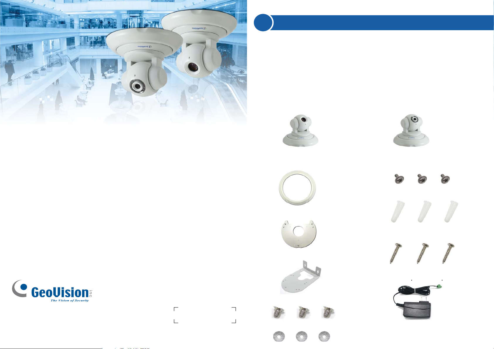
Packing List
• GV-PTZ010D / GV-PT110D camera
or
GV-PTZ010D GV-PT110D
• Mounting cover
• Round screws
Thank you for purchasing GV-PTZ010D / GV-PT110D Camera. This guide is designed to
assist the new user in getting immediate results from the GV-PTZ010D / GV-PT110D
Camera. For advanced information on how to use the GV-PTZ010D / GV-PT110D Camera,
please refer to GV-IPCam H.264 User's Manual on Software DVD.
© 2010 GeoVision Inc. All rights reserved.
2010/10
English
ICH264V106-PTZ-QG-A
• Screw anchors
• Mounting base
• Long screws
• Wall mount bracket
• DC 12V power adaptor
• Short screws
• Washers
• GV-PTZ010D / GV-PT110D
software CD
Page 2
2
Hardware Installation
The GV-PTZ010D / GV-PT110D camera is designed for indoor usage.
Please make sure that the installing location is shielded from rain and
moisture. There are two ways to mount the PTZ / PT camera: Ceiling Mount
and Wall Mount.
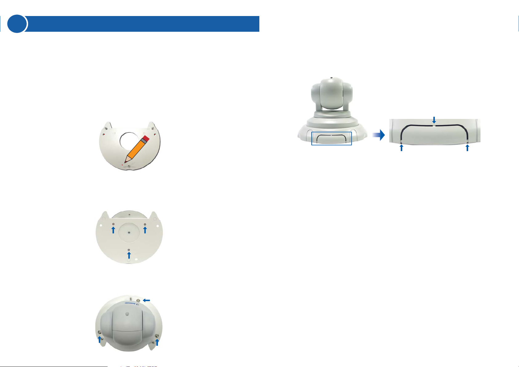
Ceiling Mount
1. Use the mounting base to make 3 marks on the wall for screw anchors.
Wall
2. Drill the marks and insert 3 screw anchors.
3. Attach the mounting base with the PTZ / PT camera with 3 short
screws.
5. Put on the mounting cover. To fit the installation environment, you can
cut the parts indicated by arrows to make an opening for wires and
cables.
4. Fix the mounting base (now with the PTZ / PT camera attached) to the
wall with 3 long screws.
Page 3
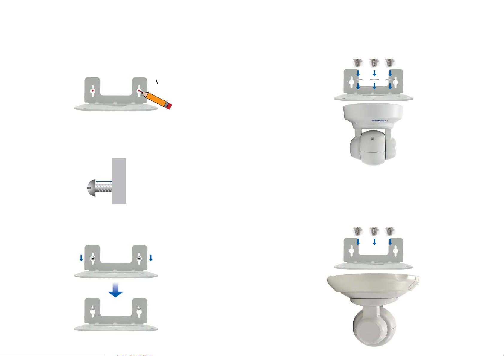
Wall Mount
You may mount GV-PTZ010D / GV-PT110D camera on the wall, with or
without the mounting cover.
1. Take the wall mount bracket and make 2 marks on the wall for screw
anchors.
Wall
2. Drill the marks and insert 2 screw anchors.
3. Insert the long screws and leave enough distance (approximately 2
mm) to hang the wall mount bracket later.
2mm
Long Screw
Wall
4. Hang the wall mount bracket on the screws and push the wall mount
bracket downward. Tighten the long screws to the wall.
5. Without Mounting Cover
• Attach the wall mount bracket with the PTZ / PT camera using 3
washers and 3 round screws.
Screw
Washer
With Mounting Cover
• To install mounting cover, attach the mounting base to the camera
and then put on the mounting cover. See steps 3 and 5 in the
Ceiling Mount section.
• Attach the wall mount bracket with the PTZ / PT camera using 3
round screws.
Screw
Page 4
3
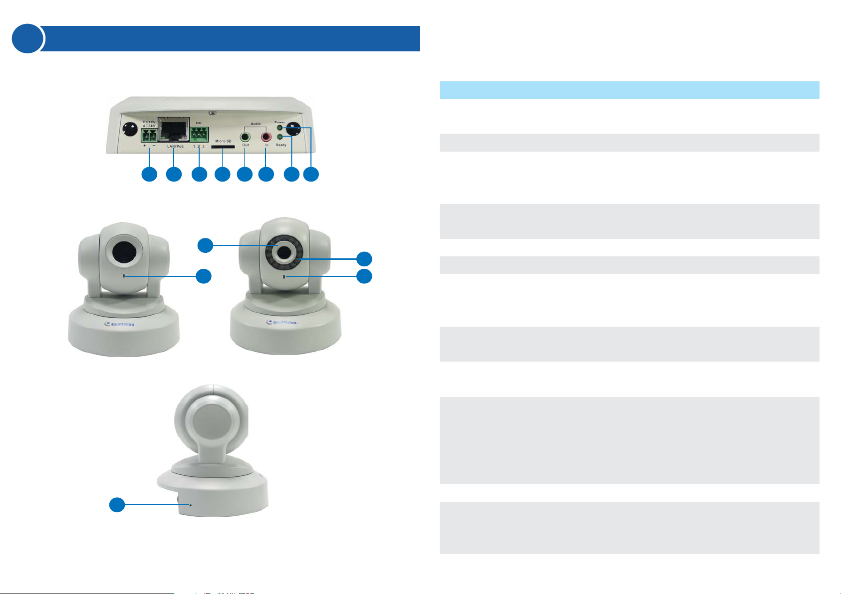
Overview
1 2 3 4 5 6 8
9
11
GV-PTZ010D GV-PT110D
Name
No.
DC 12V / AC 24V
1
Terminal Block
2
LAN/PoE
3
I/O Terminal Block
7
4
Micro SD Card Slot
5
Audio Out
10
11
6
Audio In
7
Status LED
8
Power LED
9
Focus Ring
Description
Connects to a DV 12V or AC 24V Power
Adapter.
Connects to a 10/100 Ethernet or PoE.
Connects to I/O devices. For details, see 5.7
I/O Terminal Block in the GV-IPCam H.264
User’s Manual on the software CD.
Inserts a micro SD/SDHC card to store
recording data.
Connects a speaker for audio output.
Connects a microphone for audio input.
Turns green when the system operates
normally and turns off when system error
occurs.
Turns green when the power is on and turns off
when the power is off.
Manually rotates this ring left or right to adjust
12
10
11
12
IR
Microphone
Default
focus.
Turns on to illuminate a surveillance area by
infrared light to produce clearer images during
the night. For details, see 9.1.1 Video Settings
in the GV-IPCam H.264 User’s Manual on the
software CD.
Records the sounds.
Resets to default factory settings. See 10.
Restoring to Default Settings later in the Quick
Start Guide.
Page 5

4
Accessing the PTZ / PT Camera
System Requirement
To access GV-PTZ010D / GV-PT110D camera through the Web browser,
ensure your PC connects to the network properly and meets the system
requirement below:
• Microsoft Internet Explorer 6.x or later
Note: For the users of Internet Explorer 8, additional settings are
required. For details, see Appendix B in GV-IPCam H.264 User’s
Manual on the software CD.
Connecting the Cables
Connect GV-PTZ010D / GV-PT110D camera with a standard network cable
and the supplied power adaptor. Alternatively, you can connect a Power
over Ethernet (PoE) adaptor and the power will be supplied over the
network cable.
Assigning an IP Address
Designed for use on the network, assign an IP address to make the
GV-PTZ010D / GV-PT110D camera accessible:
1. Open your web browser, and type the default IP address
http://192.168.0.10
2. In both the Login and Password fields, type the default value admin
and click Apply.
.
3. In the left menu, select Network and then LAN to configure the
network settings.
4. Select Static IP address. Type the IP Address, Subnet Mask,
Router/Gateway, Primary DNS and Secondary DNS in the Configure
connection parameters section.
5. Click Apply. The camera is now accessible by entering the assigned
IP address on the Web browser.
Important:
1. Dynamic IP Address and PPPoE should only be enabled if you
know which IP address the camera will get from the DHCP server or
ISP. Otherwise you must use the Dynamic DNS service to obtain a
domain name linked to the camera’s changing IP address first.
2. If Dynamic IP Address or PPPoE is enabled and you cannot
access the camera, you may have to reset the camera to its factory
default and then perform the network settings again. To restore
factory settings, see 10. Restoring to Default Settings in the Quick
Start Guide.
Page 6

5
The Web Interface
1 2 3 4 5 6 7
11
8
9
10
Name
No.
Play
1
Stop
2
Microphone
3
Speaker
4
Snapshot
5
File Save
6
Full Screen
7
Show System Menu
8
PTZ Control Panel
9
I/O Control
10
Control Panel
11
Function
Plays live video.
Stops playing video.
Talks to the surveillance area from the local
computer.
Listens to the audio around the camera.
Takes a snapshot of live video.
Records live video to the local computer.
Switches to full screen view. Right-click the
image to see additional options.
Brings up these functions: Alarm Notify, Video
and Audio Configuration, Remote Config, Show
Camera Name and Image Enhance.
Displays the PTZ Control Panel or Visual PTZ.
Enables the I/O Control Panel and Visual
Automation.
Displays the camera information, video
settings, audio data rate, I/O device status,
images captured upon alarm, and GPS location
of the camera. Also allows you to adjust image
quality and install the program from the hard
drive.
Continued on the reverse
Page 7

6
Enabling PTZ / PT Control Panel
Buttons on the PTZ / PT control panel:
The PTZ / PT control panel allows you to adjust focus, image quality and
configure camera movements. To enable the PTZ / PT control panel, click
the PTZ Control button on the Web interface and select PTZ Control
Panel. The PTZ / PT control panel appears.
1
3
2
4
5
No.
Name
1
Exit
2
Pan / Tilt Control
3
Home
4
Zoom In / Out
5
Focus In / Out
6
Option
7
Show Preset
Description
Closes the PTZ / PT control panel.
Moves the PTZ / PT camera to 8 directions: up,
down, left, right, left up, left down, right up and
right down.
Brings the camera view back to the home point
where the camera faces front at a 90 degree
angle to the base of the device.
Shortens (zoom in) or lengthens (zoom out) the
apparent distance between the camera and the
view.
Adjusts the sharpness of the camera view.
Brings up these functions: Auto focus, PTZ
speed, maximum number of preset points,
image quality, Preset point, Sequence, Auto
Pan, digital zoom and camera default loading.
Opens and closes the number pad.
6
7
Note : The functions related to focus, zoom and image quality on the
control panel are only available in GV-PTZ010D. For details on the
functions supported on the GV-PT110D, see 6.8 PT Control in the
GV-IPCam H.264 User’s Manual on the software CD.
For details of the PTZ / PT control panel, see Chapter 5, GV-IPCam H.264
User’s Manual on the software CD.
Page 8

7
Conguring a Preset Point
You can configure the GV-PTZ010D / GV-PT110D camera to automatically
move toward a point in live view. You can save up to 256 Preset points.
Follow the steps below:
1. On the PTZ / PT control panel, use Pan / Tilt Control buttons to move
the camera to a desired point in live view.
2. To save this Preset point, click the Option button, select Preset Set and
select the desired Preset number.
3. A confirmation message appears. Click Yes.
4. To configure more Preset points, repeat steps 1 to 3 and select a
different Preset number to save.
To start a Preset movement, click the Option button on the control panel,
select Preset Go, and select a Preset number which has been set
previously.
To stop a Preset movement, click the Home button or click any of the Pan /
Tilt Control buttons.
1
4
2
3
Page 9

8
Conguring a Sequence
You can also configure the GV-PTZ010D / GV-PT110D camera to perform a
Sequence, which links up more than two Preset points to form a series of
movements. Up to 8 Sequences can be created.
1. Follow the steps in 7. Configuring a Preset Point to save desired Preset
points.
2. On the PTZ / PT control panel, select Option, select Setup, and click the
Open button. The VISCA OSD Configuration dialog box appears.
4. Use the Index drop-down list to select a Sequence number.
5. Use the Point drop-down list to select the number of Preset points in the
Sequence.
6. Use the Preset drop-down list to select the Preset points.
7. Use the Dwell Time drop-down list to select the staying time at a Preset
point.
8. Use the Speed drop-down list to select the speed.
9. To configure another Sequence, repeat steps 4 to 8 and select a different
Index number.
10.Click Save to complete the settings.
To start a Sequence, click the Option button on the control panel, select
Auto and select a Go Sequence number which you have set previously.
To stop a Sequence, click on a Pan / Tilt Control button or the Home
button.
3. Select Sequence.
Page 10

9
Upgrading System Firmware
GeoVision will periodically release updated firmware on the web site. To load
the new firmware into the GV-PTZ010D / GV-PT110D camera, read the
important note and then follow the instruction below.
Important:
1. While the firmware is being updated,
A) the power supply must not be interrupted, and
B) do not unplug the Ethernet cable if the cable is the source of
power supply (Power over Ethernet or PoE supported).
2. Do not turn the power off within 10 minutes after the firmware is
updated.
3. If you use the IP Device Utility for firmware upgrade, the computer
used to upgrade firmware must be under the same network of the
camera.
1. In the Live View window, click the Show System Menu button, select
Remote Config, and click the Firmware Upgrade tab. This dialog box
appears.
2. Click the Browse button to locate the firmware file (.img) saved at your
local computer.
3. Click the Upgrade button to start the upgrade.
WARNING: The interruption of power supply during updating causes
not only update failures but also damages to the camera. In this case,
please contact your sales representative and send your device back to
GeoVision for repair.
Page 11

10
Restoring to Default Settings
You can restore the system default settings of the GV-PTZ010D /
GV-PT110D directly on the camera or through the Web interface.
Directly on the Camera:
1. Unplug the power cable or the network cable (if it is also used as the
power supply).
2. Press and hold the Default button.
Default button
3. Plug the power and network cable back.
4. Hold the Default button until the two network LEDs fade. This will take
about 25 seconds.
Using the Web Interface:
1. On the left menu of Web interface, select Management and select
Tools. The Additional Tools dialog appears.
2. Click the Load Default button in the System Settings section.
Note: To restore camera settings in GV-PTZ010D, including settings on
Iris, White Balance, Image Reverse and Other, see 11.3 Restoring to
Factory Default Settings in the GV-IPCam H.264 User’s Manual on the
software CD.
Network LEDs
5. When default loading is complete, the camera will pan and tilt to its full
range and return to the home point.
Page 12

9F, No. 246, Sec. 1, Neihu Rd., Neihu District, Taipei, Taiwan
Tel: +886-2-8797-8376 Fax: +886-2-8797-8335
support@geovision.com.tw
http://www.geovision.com.tw
 Loading...