

Page 1
GV-IPCam H.264
Hardware Manual
PT Camera
PTZ Camera
Before attempting to connect or operate this product,
please read these instructions carefully and save this manual for future use.
ICH264TG2V10
Page 2

© 2015 GeoVision, Inc. All rights reserved.
Under the copyright laws, this manual may not be copied, in whole or in
part, without the written consent of GeoVision.
Every effort has been made to ensure that the information in this manual is
accurate. GeoVision, Inc. makes no expressed or implied warranty of any
kind and assumes no responsibility for errors or omissions. No liability is
assumed for incidental or consequential damages arising from the use of
the information or products contained herein. Features and specifications
are subject to change without notice. Note: no memory card slot or local
storage function for Argentina.
GeoVision, Inc.
9F, No. 246, Sec. 1, Neihu Rd.,
Neihu District, Taipei, Taiwan
Tel: +886-2-8797-8377
Fax: +886-2-8797-8335
http://www.geovision.com.tw
Trademarks used in this manual: GeoVision, the GeoVision logo and GV
series products are trademarks of GeoVision, Inc. Windows and Windows
XP are registered trademarks of Microsoft Corporation.
September 2015
Page 3

Page 4

Content
Content ................................................................................i
Options .............................................................................. iii
Chapter 1 PTZ Camera .....................................................
1.1 Packing List..............................................................................2
1.2 Features...................................................................................
1.3 Overview ..................................................................................
1.4 Installation................................................................................
1.4.1 Ceiling Mount...............................................................
1.4.2 L-Shaped Wall Mount...................................................
1.5 Connecting the Camera..........................................................
1.6 Focus Adjustment...................................................................
1.7 I/O Terminal Block..................................................................
1.7.1 Pin Assignment..........................................................
1.7.2 Voltage Load Expansion (Optional)............................
1.8 PTZ Control............................................................................
1.8.1 The PTZ Control Panel ...............................................
1.8.2 Automatic Focus.........................................................
1.8.3 PTZ Camera Settings..................................................
1.8.4 Image Settings............................................................
1
11
12
13
13
14
15
15
17
17
19
3
4
6
6
8
1.8.5 Preset Settings ...........................................................
22
i
Page 5

1.8.6 Sequence Settings...................................................... 25
1.8.7 Auto Pan Settings .......................................................
27
1.8.8 System Configuration .................................................
1.9 Loading Factory Default..........................................................
Chapter 2 PT Camera......................................................
2.1 Packing List............................................................................
2.2 Features.................................................................................
2.3 Overview ................................................................................
2.4 Installation..............................................................................
2.5 Connecting the Camera..........................................................
2.6 Focus Adjustment...................................................................
2.7 I/O Terminal Block..................................................................
2.7.1 Pin Assignment..........................................................
2.7.2 Voltage Load Expansion (Optional)............................
2.8 PT Control..............................................................................
2.9 Loading Factory Default ..........................................................
30
31
33
33
35
36
38
38
38
39
39
39
40
42
ii
Page 6

Options
Optional devices can expand your camera’s capabilities and versatility.
Contact your dealer for more information.
Device Description
The power adapter is available for all PT and PTZ
Power Adapter
GV-PA191 PoE
Adapter
GV-POE Switch
GV-Relay V2
Camera. Contact your sales representative for the
countries and areas supported.
The GV-PA191 PoE adapter is designed to provide
power and network connection to the cameras over
a single Ethernet cable.
The GV-POE Switch is designed to provide power
along with network connection for IP devices. The
GV-POE Switch is available in various models with
different numbers and types of ports.
The GV-Relay V2 is designed to expand the voltage
load of GV IP devices. It provides 4 relay outputs,
and each can be set as normally open (NO) or
normally closed (NC) independently as per your
requirement.
iii
Page 7

Page 8

PTZ Camera
1
Chapter 1 PTZ Camera
The GV-PTZ010D camera is a ceiling-mount device that provides panning,
tilting and zooming functions. The camera is designed to monitor a wide
area and also to focus on a specific part on the live view when suspicious
events occur. There are two models:
Model Model No. Description
GV-PTZ010D
GV-PTZ010D-N
GV-PTZ010D-P
NTSC, IPCAM, 10x Optical Zoom,
D1, H.264, Fixed Iris
PAL, IPCAM, 10x Optical Zoom,
D1, H.264, Fixed Iris
1
Page 9
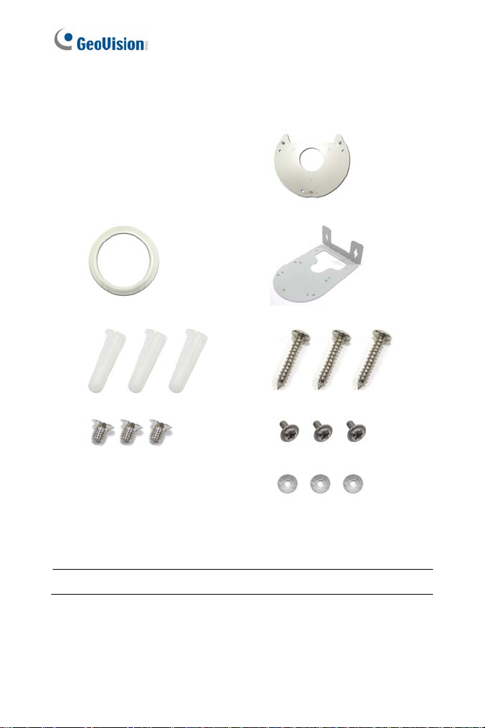
1.1 Packing List
GV-PTZ010D
Mounting Cover
Mounting Base
Wall Mount Bracket
Sc rew Anc hor x 3
Long Sc rew x 3
Short Sc rew x 3
Round Sc rew x 3
GV-PTZ010D Software CD Washer x 3
GV-NVR Software DVD Terminal block
Warranty Card
Note: Power adapter can be purchased upon request.
2
Page 10

1.2 Features
1/4" CCD image sens or
Dual s treams from H.264, MPEG4 or MJPEG
Up to 30 fps at 704 x 480 / Up to 25 fps at 704 x 576
Day and night funct i on (el ect roni c)
10x optical zoom lens
10x digital zoom
Pan and tilt (P an: -175° ~ 175°; Tilt: -45° ~ 90°)
Micro SD card slot (SD/SDHC) for local storage
Two-way audio
One sensor input and alarm output
Input -triggered Preset points
Motion detection
Privacy mask
IP address filtering
DC 12 V / AC 24 V / PoE (IEEE 802.3af)
Support for iPhone, iPad, Android and 3GPP
28 languages on Web interfac e
PTZ Camera
1
3
Page 11
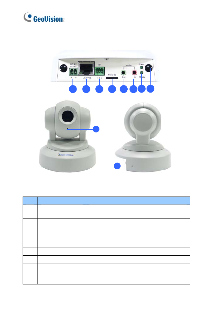
1.3 Overview
21 3 4 5 6
9
10
Figure 1-1
No. Name Description
DC 12V / AC 24V
1
Terminal Block
LAN/PoE Connects to a 10/100 Ethernet or PoE.
2
I/O Terminal Block For details, see 1.7 I/O Terminal Block.
3
Memory Card Slot
4
Audio Out Connects a speaker for audio output.
5
Audio In Connects a microphone for audio input.
6
Stat us LED
7
Connects to a DV 12V or AC 24V Power
Adapter.
Inserts a micro SD ca r d (SD/SDHC, ve r sio n
2.0 only, Class 10) to store recording data.
Turns green when the system operates
normally and turns off when system error
occurs.
87
4
Page 12

No. Name Description
Power LED
8
Microphone Records the sounds.
9
Default
10
Turns green when the power is on and
turns off when the power is off.
Resets the camera to factory default
settings. For details, see 1.9 Loading
Factory Default.
PTZ Camera
1
5
Page 13
1.4 Installation
The GV-PTZ010D / GV-PT series is designed for indoor usage. Make sure
that the installing location is shielded from rain and moisture. There are two
ways to mount the PTZ / PT Camera: Ceiling Mount and L-Shaped Wall
Mount.
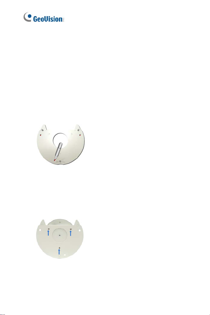
1.4.1 Ceiling Mount
1. Use the mounting base to make 3 marks on the wall for screw
anchors.
wall
Figure 1-2
2. Drill the marks and insert 3 screw anchors.
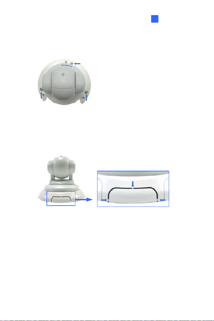
3. Attach the mounting base with the PTZ / PT Camera with 3 short
screws.
Figure 1-3
6
Page 14
PTZ Camera
1
4.
Fix the mounting base (now with the PTZ / PT Camera attached) to
the wall with 3 long screws.
Figure 1-4
5. Put on the mounting cover. To fit the installation environment, you can
cut the parts indicated by arrows to make an opening for wires and
cables.
Figure 1-5
7
Page 15
1.4.2 L-Shaped Wall Mount
You may wall-mount the GV-PTZ010D / GV-PT series with or without the
mounting cover.
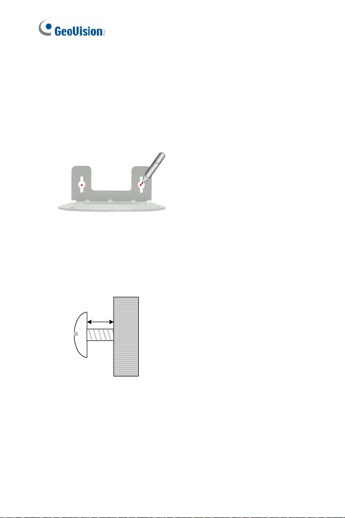
1. Take the wall mount bracket and make 2 marks on the wall for
screw anchors.
wall
Figure 1-6
2. Drill the marks and insert 2 screw anchors.
3. Insert the long screws and leave enough distance (approximately 2
mm) to hang the wall mount bracket later.
2 mm
Long
Screw
Figure 1-7
8
Wall
Page 16

PTZ Camera
1
Hang the wall mount bracket on the screws and push the wall mount
4.
bracket downward. Make sure the long screws are tightened.
Figure 1-8
5. Without Mounting Cover
Attach the wall mount bracket with the PTZ / PT Camera using 3
washers and 3 round screws.
Screw
Washer
Figure 1-9
9
Page 17

With Mounting Cover
To install the mounting cover, attach the mounting base t o the
camera and then put on the mounting cover. See steps 3 and 5
in the Ceiling Mount section.
Attach the wall mount bracket with the PTZ / PT Camera using 3
round screws.
10
Figure 1-10
Page 18

1.5 Connecting the Camera
PTZ Camera
1
2
13 4 2
Figure 1-11
1. Use a standard network cable to connect the camera to your network.
2. Optionally connect a speaker and an external microphone.
3. Connect power using one of the following methods:
plugging the power adapter to the power port.
using the Power over Ethernet (PoE) function to provide power
over the network cable.
4. Optionally connect to an input / output device. For details, see 1.7 I/O
Terminal Block.
5. The status LED of the camera will be on.
6. Access the camera. See 2.1. Accessing the Live View, GV-IPCam
H.264 Firmware Manual.
11
Page 19

1.6 Focus Adjustment
On initial installation, it is advised that you adjust the focus for image clarity.
Print out the diagram of radiating lines included on Software DVD and hang
up the diagram at the surveillance area. Use the Zoom In / Out and Focus
In / Out buttons on the PTZ control panel from the Web interface (No.4 and
5, Figure 1-15) and adjust the PTZ Camera until it displays clear radiating
lines as shown in picture on the left.
Good focus Poor focus
Figure 1-12
To access live view for the first time or to assign an IP address, see 2.1
Accessing the Live View, GV-IPCam H.264 Firmware Manual.
12
Page 20

PTZ Camera
1
1.7 I/O Terminal Block
The 3-pin terminal block, located on the back panel of the PTZ Camera,
provides the interface to one digital input and one digital output. The I/O
terminal block can be used for applications such as motion detection, event
alerts via E-Mail and FTP, and center monitoring through Center V2 and
VSM.
1.7.1 Pin Assignment
The pin assignment for the terminal block:
For details on how to enable an installed I/O device, see 4.2 I/O Settings,
GV-IPCam H.264 Firmware Manual.
I/O
123
Figure 1-13
Pin Function
1 Output
2 GND
3 Input
13
Page 21

1.7.2 Voltage Load Expansion (Optional)
The camera can only drive a maximum load of 200mA 5V DC. To expand
the maximum voltage load to 10A 250V AC, 10A 125V AC or 5A 100V DC,
connect the camera to a GV-Relay V2 module (optional product). Refer to
the figure and table below.
Output Device
Connect to Power
I/O
2
3
1
Figure 1-14
GV-Relay V2 I/O Wires
COM Pin 2 (Ground)
DO1 Pin 1 (Output)
14
Page 22

PTZ Camera
1
1.8 PTZ Control
After you have installed the PTZ Camera on network and accessed the
camera’s Web interface you are ready to configure the PTZ Camera.
To see how to install the PTZ Camera on network, see Getting Started,
Chapter 2, GV-IPCam H.264 Firmware Manual. To see how to access to
live image, see 3.1 Accessing Your Surveillance Images, GV-IPCam H.264
Firmware Manual.
1.8.1 The PTZ Control Panel
The control panel allows users to adjust focus, image quality and configure
camera movements. On the main page, click the PTZ Control button
(No. 9, Figure 20-3) and select PTZ Control Panel. The PTZ control panel
appears.
1
23
4
5
6
7
Figure 1-15
15
Page 23

Buttons on the PTZ control panel:
No. Name Description
1 Exit Closes the PTZ control panel.
Moves the PTZ Camera to 8 directions:
2 Pan / Tilt Control
3 Home
4 Zoom In / Out
5 Focus In / Out Adjusts the sharpness of the camera view.
6 Option
7 Show Preset
up, down, left, right, left up, left down, right
up and right down.
Brings the camera view back to the home
point where the camera faces front at a 90
degree angle to the base of the device.
Shortens (zoom in) or lengthens (zoom
out) the apparent distance between the
camera and the view.
Brings up these functions: Auto focus,
PTZ speed, maximum number of preset
points, image quality, Preset point,
Sequence, Auto Pan, digital zoom and
default loading.
See 1.8.2 Automatic Focus,
1.8.3 PTZ Camera Settings,
1.8.4 Image Settings,
1.8.5 Preset Settings,
1.8.6 Sequence Settings,
1.8.7Auto Pan Settings,
1.8.8 System Configuration.
Opens and closes the number pad. For
details, see 1.8.5 Preset Settings.
Note: For GV-IP Cameras equipped with varifocal motorized lens,
the following functions of PTZ panel are supported: Zoom In/Out, Focus
In/Out, Option (Auto Focus, Preset Set, Preset Go) and Show Preset.
16
Page 24

PTZ Camera
1
1.8.2 Automatic Focus
When the camera view is fuzzy, you may use the auto focus feature to
obtain a sharper view. On the PTZ control panel, click the
(No. 6, Figure 1-15) and select
AF for automatic focus.
Option button
1.8.3 PTZ Camera Settings
Accessing the PTZ Camera Settings
To access PTZ camera settings, click the Option button (No. 6, Figure 1-
15) on the PTZ control panel and select
appears.
Setup. The setup dialog box
Figure 1-16
17
Page 25

PT Speed: Determines the panning (horizontal movement) and tilting
(vertical movement) speed when using the
on the PTZ control panel. The drop-down list contains 5 speed
settings: 1 is the slowest and 5 the fastest.
Zoom Speed: Determines the zooming speed. The drop-down list
contains 4 speed settings: 1 is the slowest and 4 the fastest.
Max. Preset: Determines the maximum number of Preset points
allowed to be configured and accessed. The number of Preset points
ranges from 16 to 256.
Accessing the VISCA OSD Configuration
The VISCA OSD Configuration contains three groups of settings: image
settings, PTZ settings and system configuration. To access these settings,
click the
The dialog box appears. Alternatively, you can click
on the Web interface and select
Option button (No.6, Figure 1-15), select Setup and click Open.
PTZ Setting.
Pan / Tilt Control buttons
Digital I / O and PT Z
18
Figure 1-17
Page 26

PTZ Camera
1
1.8.4 Image Settings
Image Setting provides features on iris control, white balance, image
orientation and other image processing tools to generate clearer images.
To access these features, open the VISCA OSD Configuration dialog box
and select
[Iris] adjusts the amount of exposure.
ALC: Automatic Light Control (ALC) is used to adjust light levels.
AES: Automatic Electronic S hutt er (AES) adj usts the amount of
Image Setting.
Auto: The amount of exposure is automaticall y adjust ed. Select
Auto to enable this option. If the adjusted image is still too dark or
bright, move the slider. A higher value makes the image brighter.
Fixed: The amount of exposure is controlled by different aperture
size. Use the slider to select from 0 to 8. A higher value signifies a
bigger aperture and therefore makes the image brighter.
exposure by different shutter speeds.
Auto: The shutter speed is automatically adjust ed. To enable this
option, select
Auto. I f the adjusted image is still too dim or bright,
use the slider to select from 0 to 8. A higher value indicates a
slower shutter speed and therefore produces brighter image.
Fixed: The shutter speed for each level is fixed. Use the slider to
select from 0 to 8. A higher value indicates a faster shutter speed
and therefore produces a dimmer image.
[White Balance]
the human eye.
Adjusts the color intensity to make the images normal to
ATW: Auto Tracking White Balance (ATW) automatically adjusts the
color intensity for scenes with changing light source. Use the slider to
select from 0 to 8. A higher value produces a brighter image and a
lower value produces a more yellowish image.
19
Page 27

AWB: Automatic Whit e Balance (AWB) automatically compensates
for colors under different light levels. AWB is ideal for scenes with a
fixed light source. Use the slider to select from 0 to 8. A higher value
produces a brighter image and a lower value produces a dimmer
image.
R Gain: Adj usts the red el ement of t he live view. Us e the slider to
select from 0 to 8. A higher value indicates a stronger degree of red.
B Gain: Adj usts the blue element of the live view. Us e the sli der to
select from 0 to 8. A higher value indicates a stronger degree of blue.
[Image Reverse]
Positive/Negative: With the Positive mode, the colors in the live view
appear as it is through the eye. With the negative mode, colors in live
view are changed to their complementary colors (opposite colors), i.e.
black will be changed to white, red to green etc. Use the drop-down
list to select between
H Reverse: Reverses the view horizontally. Use the drop-down list to
select On or Off.
V Reverse: Revers es the view vertically. Use the drop-down list to
select On or Off.
Positive and Negative mode.
[Other]
BLC: Backlight Compensation (BLC) is used to compensate AGC in
adjusting color intensity. For scenes with strong light in the
background and dim light in the foreground, AGC is not effective
because AGC averages the light intensity of a whole frame. BLC
compensates for this characteristic by restric ting AGC to adjust color
intensity of a specific area. To turn on, use the drop-down list, select
On, and select a level among 0 to 7. A higher value indicates a
stronger compensation effect.
20
Page 28

PTZ Camera
1
AGC
Freeze: Instantly freezes the live view image when On is selected.
AGC: Automatic Gain Control (AGC) utilizes an electronic circuit
which amplifies video signal when the signal strength falls below a
given value due to lack of the light on the camera. Adjust camera
sensitivity to provide clear images. Under strong light int ensi t y,
AGC decreases the camera sensitivity to produce dimmer images.
Under weak light intensity, AGC increases the camera sensitivi ty
to produce brighter images. To adjust AGC, use the slider to select
among 0 to 8. A higher value produces brighter images.
Sense Up: Use the slider to select among 0 to 8. A higher value
produces brighter images.
APC: Aperture Compensation (APC) is used to adjust the sharpness
of the image.
H Gain: Sharpens the horizontal elements of the image. Use the
slider to adjust the horizontal compensation between 0 and 12.
V Gain: Sharpens the vertical elements of the image. User the
slider to adjust the vertical compensation between 0 and 12.
Gamma: Adjusts the contrast of the image. Use the drop-down list to
select between 1 and 2. The “2” option produces stronger contrast.
21
Page 29

1.8.5 Preset Settings
For PTZ Camera to automatically move toward a point in live view,
establish a Preset. A Preset is a point in live view that can be configured
and saved for future use. The PTZ Camera allows up to
For details on the maximum number of Preset points, see 1.8.3 PTZ
Camera Settings.
Configuring a Preset Point
To configure a Preset point:
1. Use one of the
move the camera to a desired point in live view.
2. To save this Preset point, click the
select
Preset Set and select the desired Preset number
3. A confirmation message appears. Click
4. To configure more Preset points, repeat steps 1 to 3 and select a
different Preset number to save.
Pan / Tilt Control buttons (No. 2, Figure 1-15) to
Option button (No. 6, Figure 1-15),
Yes.
256 Preset points.
22
Page 30

Renaming a Preset Point
To rename a Preset point:
1. Click the
select
Option button (No. 6, Figure 1-15), select Preset Set and
Naming. The dialog box appears.
Figure 1-18
PTZ Camera
1
2. Cli ck the P reset point you wish to rename and type the new name in
the blank at the top.
3. Click
and click
OK to save.
23
Page 31

Starting and Stopping a Preset Point
To start a Preset movement, click the Option button (No. 6, Figure 1-15),
select
Preset Go, and select a Preset number which has been set
previously.
Alternatively, you may use the number pad on the PTZ control panel to
enable a Preset movement:
1. Click the
pad.
2. Cli ck the num ber of Preset point.
3. Click
To stop a Preset movement, click the
click one of the
Show Preset button (No. 7, Figure 1-15) to open the number
to start.
Home button (No. 3, Figure 1-15) or
Pan / Tilt Control button (No. 2, Figure 1-15).
24
Page 32

PTZ Camera
1
1.8.6 Sequence Settings
For PTZ Camera to automatically perform a series of movements, you can
configure a Sequence. A Sequence links up more than two Preset points to
form a sequence of movements. Up to
8 Sequences can be created.
Configuring a Sequence
1. After you have configured the Preset points you wish the camera to
follow (for details, see 1.8.5 Preset Settings), you are ready to
configure a
2. Open the VISCA OSD Configuration dialog box and select
Sequence.
Sequence.
Figure 1-19
3. Use the
4. Use the
Index drop-down list to select the Sequence number you
wish to configure. Up to 8 Indexes can be created.
Point drop-down list to select the number of Preset points to
be included in the Sequence. A Sequence can contain up to 32
Preset points.
25
Page 33

5. Use the Preset drop-down list to select the Preset points for the
Sequence.
6. Use the
7. Use the
8. To configure another Sequence, repeat steps 3 to 8 and select a
9. Click
Starting and Stopping a Sequence
To start a Sequence, click the Option button (No. 6, Figure 1-15) select
Auto and select a Go Sequence number which you have set previously.
To stop a Sequence, click on a
15) or the
Dwell Time drop-down list to select the staying time that the
camera stays at the Preset point. The dwell time ranges from 0 to 127
seconds at an interval of 0.5 second.
Speed drop-down list to select the speed at which the
camera moves toward the Preset point.
different Index number.
Save to complete the settings.
Pan / Tilt Control button (No. 2, Figure 1-
Home button (No. 3, Figure 1-15).
26
Page 34

PTZ Camera
1
1.8.7 Auto Pan Settings
For the PTZ Camera to survey a horizontal view, establish an Auto Pan.
Up to 4 sets of Auto Pan can be created.
Configuring an Auto Pan
To configure a horizontal movement:
1. Adjust the angle of the camera view using the
buttons since any vertical movements of the camera will not be
recorded by Auto Pan.
2. On the control panel, click the
select
Auto and select a Set Auto Pan number.
3. Click the
to perform the desired movement.
4. Click the
an
Right or the Left Control buttons on the PTZ control panel
Option button (No. 6, Figure 1-15), select Auto and select
End Auto Pan number to save this configuration.
Option but ton (No. 6, Figure 1-15),
Up and Down Control
27
Page 35

Configuring the Speed of Auto Pan
You can configure the speed for each set of Auto Pan differently:
1. Open the VISCA OSD Configuration dialog box and select
Advance.
Figure 1-20
2. Select the
Speed.
3. To configure the speed of another Auto Pan, repeat step 2.
4. Click
28
Auto Pan number you wish to configure and select the
OK.
Page 36

PTZ Camera
1
Starting and Stopping Autopan
To start an Auto Pan, click the Option button (No. 6, Figure 1-15), select
Auto and select a desired Auto Pan number. The PTZ Camera will first
return to the starting position of the selected Auto Pan and proceeds with
the selected Auto Pan movement.
To stop Auto Pan, click the
and select
(No. 2, Figure 1-15) or the
Autopan Stop. Alternatively click on a Pan / Tilt Control button
Option button (No. 6, Figure 1-15), select Auto
Home button (No. 3, Figure 1-15).
Rebooting the Camera
When the system crushes and fails to respond to the PTZ control panel,
reboot the camera.
1. Open the VISCA OSD Configuration dialog box.
2. Click the
3. Wait until the camera has panned and tilted its full range and returned
to the home point.
Motor Reset button to reboot.
29
Page 37

1.8.8 System Configuration
To configure lens settings, open the VISCA OSD Configuration dialog box
and select
System Configure.
Fi
gure 1-21
Zoom + AF: Automatically focuses after zooming. It is advised to use
this feature with a zooming distance of at least 1 meter.
Digital Zoom: Allows up to 10x Digital Zoom. This function is enabled
after the Optical Zoom level is fully reached Use the drop-down list to
select among off, 2x, 4x, 6x, 8x and 10x.
Load Camera Default: Loads the factory default setting of Iris, White
Balance, Image Reverse and Other in the VISCA OSD Configuration
dialog box (Figure 1-17).
30
Page 38

PTZ Camera
1
1.9 Loading Factory Default
There are two types of default settings: camera default settings and
system default settings. Camera default settings include all settings on
Iris, White Balance, Image Reverse and Other in the VISCA OSD
Configuration dialog box (Figure 1-22). System default settings refer to all
the settings except the camera settings.
To load camera default settings:
1. On the left menu of Web interface, select Digital I/O and PTZ, select
PTZ Settings, and select System Configure. The VISCA OSD
Configure dialog box appears.
2. Click the
Load Camera Default button.
Figure 1-22
31
Page 39

To load system default settings:
1. Unplug the power cable and the network cable (or the PoE cable).
2. Press and hold the
default button.
Default button
Figure 1-23
3. Power on the camera using the power cable or the PoE cable.
4. Hold the
about 25 seconds.
5. When default loading is completed, the camera will pan and tilt to its
full range and return to the home point.
32
default button until the two network LEDs fade. This will take
Network LEDs
Figure 1-24
Page 40

PT Camera
2
Chapter 2 PT Camera
The GV-PT camera is a series of indoor pan and tilt camera that is
designed to monitor a wide surveillance area. The camera support remote
pan and tilt control and is capable of storing pre-established panning/tilting
movements and points on live view for immediate monitoring. Equipped
with IR LEDs and IR-cut filter, the GV-PT camera provides excellent image
quality in the dark.
2.1 Packing List
GV-PT130D/220D/320D
Mounting Cover
Mounting Base
Wall Mount Bracket
Sc rew Anc hor x 3
Long Sc rew x 3
33
Page 41

Short Sc rew x 3
Round Sc rew x 3
Terminal Block
Washer x 3
Power Adapter GV-IPCAM H.264 Software
DVD
GV-NVR Software DVD Warranty Card
Note: The power adapter can be excluded upon request.
34
Page 42

PT Camera
2
2.2 Features
1/2.5’’ progressive scan CMOS
Dual s treams from H.264 and MJPEG
Frame rate
Camera Model Frame Rate
GV-PT130D 30 fps at 1280 x 1024
GV-PT220D 30 f ps at 1920 x 1080
GV-PT320D 20 f ps at 2048 x 1536
Pan and tilt (P an: -175° ~ 175°; Tilt: -45° ~ 90°)
Input -triggered Preset points
One sensor input and alarm output
Buil t-in / external microphone
Micro SD card slot (SD/SDHC) for local storage
DC 12 V / AC 24 V / PoE (IEEE 802.3af)
Day/Ni ght function (with removable IR-cut filter)
NAS recording
Recordi ng assigned by GV-Edge Recording Manager (Windows &
Mac)
Intelligent IR
Wide Dynamic Range (WDR)
2-way audio
2D noise reduction
Motion detection
Defog
IP address filtering
Supports iPhone, iPad, Android & 3GPP
31 languages on Web interfac e
ONVIF (Profile S) conformant
35
Page 43

2.3 Overview
1 2 3 4 5 6 7 8
9
10
11
12
Figure 2-1
No. Name Description
DC 12V / AC 24V
1
Terminal Block
2
LAN / PoE Connects t o a 10/100 Ethernet or PoE.
3
I/O Terminal Block For details, see 2.7 I/O Terminal Block.
4
Memory Card Slot
5
Audio Out Connects a speaker for audio output.
6
Audio In Connects a microphone for audio input.
Connects to a DV 12V or AC 24V Power
Adapter.
Inserts a micro SD ca r d (SD/SDHC, ve r sio n
2.0 only, Class 10) to store recording data.
36
Page 44

No. Name Description
Turns green when the system operates
7 Status LED
8 Power LED
9 Focus Ring
10 IR
11 Microphone Records the sounds.
12 Default
normally and turns off when system error
occurs.
Turns green when the power is on and turns
off when the power is off.
Manually rotates this ring left or right to
adjust focus.
Turns on to automatically illuminate a
surveillance area by infrared light to
produce clearer images during the night.
Resets the camera to system default
settings. For details, see 2.9 Loading
Factory Default Settings.
PT Camera
2
37
Page 45

2.4 Installation
For installation procedures of the GV-PT Camera, see 1.4 Installation.
2.5 Connecting the Camera
For procedures of connecting the GV-PT Camera, see 1.5 Connecting the
Camera.
2.6 Focus Adjustment
After you have followed 1.5 Connecting the Camera and connected all the
necessary cables and wires, follow the steps below to adjust image clarity.
1. Access the live view. For details, see 2.1 Accessing the Live View,
GV-IPCam H.264 Firmware Manual.
2. Adjust image clarity using the GV-IP Device Utility program. For
details, see 2.2 Adjusting Image Clarity, GV-IPCam H.264 Firmware
Manual.
38
Page 46

PT Camera
2
2.7 I/O Terminal Block
The 3-pin terminal block, located on the back panel of the PT Camera,
provides the interface to one digital input and one digital output. The I/O
terminal block can be used for applications such as motion detection, event
alerts via E-Mail and FTP, and center monitoring through Center V2 and
VSM.
2.7.1 Pin Assignment
The pin assignment for the terminal block:
Pin Function
1 Output
123
Figure 2-2
For details on how to enable an installed I/O device, see 4.2 I/O Settings,
GV-IPCam H.264 Firmware Manual.
2 GND
3 Input
2.7.2 Voltage Load Expansion (Optional)
You can install a GV-Relay V2 to expand the maximum voltage load of
your GV-PT Camera. For details, see 1.7.2 Voltage Load Expansion.
39
Page 47

2.8 PT Control
The GV-PT Camera shares similar user interfaces and features with the
GV-PTZ010D camera. See below for the supported functions and
reference.
Supported Function Description
PT Control Panel The PT camera supports the following buttons
on the control panel:
Home, Option and Show Preset. For details,
see 1.8.1 The PTZ Control Panel.
Exit, Pan / Tilt Control,
PT Camera Settings Contains settings on PT speed and the
maximum number of preset points. For details,
see Accessing the PTZ Camera Settings in
1.8.3 PTZ Camera Settings.
Preset point A Preset point is a point in live view that can
be configured and accessed using a hot key.
For details, see 1.8.5 Preset Settings.
40
Page 48

PT Camera
2
Supported Function Description
Sequence A Sequence consists of a series of Preset
points. Configure a Sequence to direct the
camera to perform s series of movements. For
details, see 1.8.6 Sequence Settings.
Auto Pan The camera can be configured to monitor the
surveillance area in a horizontal movement.
For details, see 1.8.7 Auto Pan Settings.
41
Page 49

2.9 Loading Factory Default
1. Keep the power and network cables connected to the camera.
2. Use a pin to press and hold the
default button on the panel.
Default button
Figure 2-3
3. Release the
take about 8 seconds.
4. When the
settings is completed and the camera is ready for use.
default button when the status LED blinks. This shall
status LED turns orange, the process of loading default
42
 Loading...