

Page 1
GV-IP LPR Camera
User's Manual
GV-LPC2210
GV-LPC2211
GV-LPC2011
GV-LPR1200
GV-LPC1200
GV-LPC1100
GV-IP LPR Cam 5R
Before attempting to connect or operate this product,
please read these instructions carefully and save this manual for future use.
IPLPRCAM-D
Page 2

*HR9LVLRQ,QF$OOULJKWVUHVHUYHG
8QGHUWKHFRS\ULJKWODZVWKLVPDQXDOPD\QRWEHFRSLHGLQZKROHRULQSDUW
ZLWKRXWWKHZULWWHQFRQVHQWRI*HR9LVLRQ
(YHU\HIIRUWKDVEHHQPDGHWRHQVXUHWKDWWKHLQIRUPDWLRQLQWKLVPDQXDOLV
DFFXUDWH*HR9LVLRQ,QFPDNHVQRH[SUHVVHGRULPSOLHGZDUUDQW\RIDQ\NLQG
DQGDVVXPHVQRUHVSRQVLELOLW\IRUHUURUVRURPLVVLRQV1ROLDELOLW\LVDVVXPHG
IRULQFLGHQWDORUFRQVHTXHQWLDOGDPDJHVDULVLQJIURPWKHXVHRIWKHLQIRUPDWLRQ
RUSURGXFWVFRQWDLQHGKHUHLQ)HDWXUHVDQGVSHFLILFDWLRQVDUHVXEMHFWWR
FKDQJHZLWKRXWQRWLFH
1RWH1RPHPRU\FDUGVORWRUORFDOVWRUDJHIXQFWLRQIRU$UJHQWLQD
*HR9LVLRQ,QF
)1R6HF1HLKX5G
1HLKX'LVWULFW7DLSHL7DLZDQ
7HO
)D[
KWWSZZZJHRYLVLRQFRPWZ
7UDGHPDUNVXVHGLQWKLVPDQXDO*HR9LVLRQWKH*HR9LVLRQORJRDQG*9
VHULHVSURGXFWVDUHWUDGHPDUNVRI*HR9LVLRQ,QF:LQGRZVDQG:LQGRZV;3
DUHUHJLVWHUHGWUDGHPDUNVRI0LFURVRIW&RUSRUDWLRQ
March
Page 3

Preface
Welcome to the GV-IP LPR Camera User’s Manual.
The GV-IP LPR Camera has a series of models designed to meet different needs. This
manual is designed for the following models and firmware versions:
Models Firmware Version
GV-IP LPR Camera 5R 1.01
GV-LPC1100 1.01
GV-LPC1200 1.0
GV-LPR1200 1.01
GV-LPC2210 1.02
GV-LPC2211 1.0
GV-LPC2011 1.0
Note: GV-LPC1100 is also referred to as GV-IP LPR Camera 10R.
IMPORTANT: When using GV-LPC1200 / GV-LPR1200 for the first time, you need to
remove the plastic insulation film under the battery and change the silica gel bag. For
details, see 1.3.6 Replacing the Silica Gel Bag and 1.3.7 Fitting the Battery.
i
Page 4

Contents
Naming Definition.................................................................................................... vi
Options.................................................................................................................... vii
Note for Connecting to GV-System / GV-VMS..................................................... viii
Note for Installing Camera Outdoor....................................................................... ix
Chapter 1 Introduction........................................................................................... 1
1.1 GV-IP LPR Camera 5R ..............................................................................................1
1.1.1 Feat ures ......................................................................................................... 2
1.1.2 System Requirements.................................................................................... 3
1.1.3 Packing List.................................................................................................... 4
1.1.4 Device Installation.......................................................................................... 5
1.1.5 Con necting the Camera ................................................................................. 6
1.1.6 Adju sting the Angles ...................................................................................... 7
1.1.7 Replacing the Silica Gel Bag ....................................................................... 10
1.1.8 Installing the Sun-Shield Cover.................................................................... 11
1.2 GV -LPC1100 ............................................................................................................ 12
1.2.1 Feat ures ....................................................................................................... 13
1.2.2 System Requirements.................................................................................. 14
1.2.3 Packing List.................................................................................................. 15
1.2.4 Device Installation........................................................................................ 16
1.2.5 Con necting the Camera ............................................................................... 18
1.2.6 Replacing the Silica Gel Bag ....................................................................... 21
1.3 GV -LPC1200 / LPR1200 .......................................................................................... 22
1.3.1 Feat ures ....................................................................................................... 23
1.3.2 System Requirements.................................................................................. 24
1.3.3 Packing List.................................................................................................. 25
1.3.4 Inst alling the Camera ................................................................................... 26
1.3.5 Con necting the Camera ............................................................................... 28
1.3.6 Replacing the Silica Gel Bag ....................................................................... 30
1.3.7 Fitt ing the Battery ......................................................................................... 31
1.3.8 Installing a Mini USB Cable.......................................................................... 32
1.4 GV -LPC2210 ............................................................................................................ 35
1.4.1 Feat ures ....................................................................................................... 36
1.4.2 System Requirements.................................................................................. 37
1.4.3 Packing List.................................................................................................. 38
1.4.4 Device Installation........................................................................................ 39
ii
Page 5

1.4.5 Con necting the Camera ............................................................................... 41
1.4.6 Replacing the Silica Gel Bag ....................................................................... 43
1.5 GV -LPC2211/2011.................................................................................................... 44
1.5.1 Feat ures ....................................................................................................... 45
1.5.2 System Requirements.................................................................................. 47
1.5.3 Packing List.................................................................................................. 48
1.5.4 Device Installation........................................................................................ 49
1.5.5 Con necting the Camera ............................................................................... 54
1.5.6 Replacing the Silica Gel Bag ....................................................................... 55
Chapter 2 Getting Started.................................................................................... 57
2.1 Looking Up the IP Address ....................................................................................... 57
2.2 Changing the IP Address.......................................................................................... 59
2.2 Config uring the Basics ............................................................................................. 60
Chapter 3 Accessing the Camera....................................................................... 61
3.1 Acce ssing Your Surveillance Images ....................................................................... 61
3.2 The Live View Window ............................................................................................. 63
3.3 The Control Panel of the Live View Window ............................................................ 65
3.4 Snapshot of a Live Video .........................................................................................69
3.5 V ideo Recording ....................................................................................................... 69
3.6 Picture-in-Picture and Picture-and-Picture View ...................................................... 70
3.7 Alarm Notification ..................................................................................................... 72
3.8 V ideo and Audio Configuration................................................................................. 73
3.9 Remote Configuration .............................................................................................. 74
3.10 Camera Name Display ........................................................................................... 74
3.11 Image Enhancement .............................................................................................. 74
3.12 Digit al PTZ..............................................................................................................75
3.13 I/O Control .............................................................................................................. 76
3.14 V isual Automation................................................................................................... 77
Chapter 4 Administrator Mode............................................................................ 78
4.1 V ideo & Motion ......................................................................................................... 80
4.1.1 V ideo Settings .............................................................................................. 81
4.1.2 Motion Detection / Detection Mode.............................................................. 88
4.1.3 Privacy Mask................................................................................................ 94
4.1.4 T ext Overlay ................................................................................................. 95
4.1.5 T ampering Alarm.......................................................................................... 96
iii
Page 6

4.1.6 V isual Automation ........................................................................................ 98
4.1.7 Reco gnition Engine Settings ........................................................................ 99
4.2 I/O Control .............................................................................................................. 103
4.2.1 Input Settings ............................................................................................. 103
4.2.2 Output Settings .......................................................................................... 104
4.2.3 RS485 ........................................................................................................ 106
4.3 Event s & Alerts ....................................................................................................... 107
4.3.1 E-mail ......................................................................................................... 108
4.3.2 FTP ............................................................................................................ 110
4.3.3 Cent er V2 ................................................................................................... 112
4.3.4 VSM (Vital Sign Monitor)............................................................................ 114
4.3.5 GV-Video Gateway / GV-Recording Server ............................................... 116
4.3.6 R TSP.......................................................................................................... 118
4.3.7 ONVIF ........................................................................................................ 119
4.3.8 POS ........................................................................................................... 120
4.3.9 Inquire Recognized Database.................................................................... 122
4.3.10 Re gistry Database.................................................................................... 123
4.4 Monito ring............................................................................................................... 125
4.4.1 Mo nitoring Settings .................................................................................. 125
4.5 Sched ule ................................................................................................................ 127
4.5.1 I/O Monitoring Settings .............................................................................. 127
4.5.2 Reco gnizing Schedule Settings ................................................................. 128
4.6 Network .................................................................................................................. 129
4.6.1 LAN Configuration...................................................................................... 129
4.6.2 Advanced TCP/IP....................................................................................... 131
4.6.3 UMTS ......................................................................................................... 135
4.6.4 IP Filtering .................................................................................................. 137
4.6.5 SNMP Settings........................................................................................... 138
4.7 Management .......................................................................................................... 140
4.7.1 Date and Time Settings.............................................................................. 140
4.7.2 S torage Settings......................................................................................... 142
4.7.3 User Account.............................................................................................. 144
4.7.4 Log Information .......................................................................................... 145
4.7.5 T ools........................................................................................................... 146
4.7.6 Lang uage ................................................................................................... 148
Chapter 5 Advanced Applications.................................................................... 149
5.1 Upgra ding System Firmware .................................................................................. 149
5.1.1 Using the Web Interface............................................................................. 150
iv
Page 7

5.1.2 Using the GV-IP Device Utility.................................................................... 151
5.2 Backing Up and Restoring Settings........................................................................ 154
5.3 Restoring to Factory Default Settings..................................................................... 156
5.3.1 Using the Web Interface............................................................................. 156
5.3.2 Directly on the Camera .............................................................................. 156
5.4 V erifying Watermark ............................................................................................... 158
5.4.1 Acce ssing AVI Files.................................................................................... 158
5.4.2 Run ning Watermark Proof.......................................................................... 158
5.4.3 The Watermark Proof Window ................................................................... 159
Chapter 6 DVR Configurations ......................................................................... 160
6.1 Setting Up IP Cameras on GV-System .................................................................. 161
6.1.1 Cust omizing Camera Settings ................................................................... 164
6.2 Setting Up IP Cameras on GV-VMS....................................................................... 166
6.3 Remote Monitoring with Multi View ........................................................................ 169
6.4 Remote Monitoring with E-Map .............................................................................. 171
Chapter 7 CMS Configurations......................................................................... 173
7.1 Center V2 ............................................................................................................... 173
7.2 V ital Sign Monitor ................................................................................................... 175
7.3 Disp atch Server ...................................................................................................... 176
Chapter 8 Smart Device Connection................................................................ 177
Chapter 9 GV-ASManager Connection............................................................. 178
Specifications....................................................................................................... 181
GV-IP LPR Camera 5R ................................................................................................... 181
GV-LPC1100 ................................................................................................................... 184
GV-LPC1200 / LPR1200................................................................................................. 188
GV-LPC2210................................................................................................................... 192
GV-LPC2211 / 2011 ........................................................................................................ 196
Appendix............................................................................................................... 199
A. The CGI Command .................................................................................................... 199
B. RTSP Protocol Support .............................................................................................. 200
C. Settings for Internet Explorer 8 or later ...................................................................... 201
D. Supported UMTS Protocol (3G Modem) .................................................................... 202
v
Page 8

Naming Definition
GeoVision Analog and Digital Video Recording Software. The
GV-System
GV-VMS
PC LPR
GV-System also refers to Multicam System, GV-NVR system,
GV-DVR system and GV-Hybrid DVR system at the same time.
GeoVision Video Management System for IP cameras.
PC LPR refers to GV-DVR LPR and GV-VMS LPR. A
GV-System or GV-VMS can be turned into a GV-DVR LPR /
GV-VMS LPR simply by installing the LPR Plugin and inserting
an LPR Dongle. PC LPRs are capable of comparing captured
license plates with the database from GV-ASManager.
vi
Page 9

Options
Optional devices can expand your camera’s capabilities and versatility. Contact your dealer
for more information.
Device Description
The GV-PA191 PoE adapter is designed to provide power and network
GV-PA191 PoE
Adapter
GV-PA482 PoE
Adapter
GV-PoE Switch
connection to the cameras over a single Ethernet cable. The GV-PA191
PoE adapter is only available for GV-IP LPR Camera 5R and
GV-LPC2211 / 2011.
The GV-PA482 PoE adapter is designed to provide power and network
connection to the cameras over a single Ethernet cable. The GV-PA482
PoE adapter is only available for GV-LPC1100 and GV-LPC2210.
For GV-IP LPR Camera 5R / GV-LPC2211 / LPC2011, the GV-POE
Switch is designed to provide power along with network connection for
IP devices.
For other models, the GV-POE Switch can be used for data
transmission only. It does not provide power to GV-IP LPR cameras.
The GV-POE Switch is available in various models with different
numbers and types of ports.
vii
Page 10

Note for Connecting to GV-System / GV-VMS
The GV-IP LPR Camera is designed to work with and record on GV-System / GV-VMS, a
video management system.
Once the camera is connected to the GV-System / GV-VMS, the resolution set on the
GV-System / GV-VMS will override the resolution set on the camera’s Web interface. You can
only change the resolution settings through the Web interface when the connection to the
GV-System / GV-VMS is interrupted.
viii
Page 11
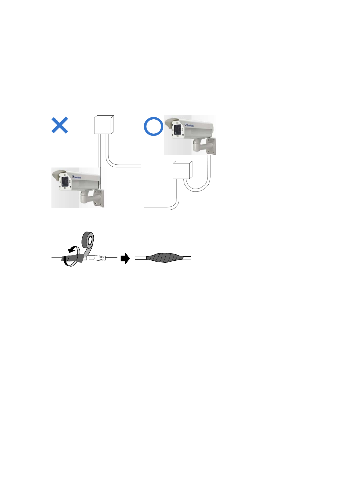
Note for Installing Camera Outdoor
When installing the GV-IP LPR Camera outdoor, mind the following:
1. Set the camera above the junction box to prevent water from entering the camera along
the cables.
2. Waterproof the PoE, power and TV-out cables with waterproof silicon rubber or the like.
3. To prevent the lens from fogging up, replace the silica gel bag every time you open the
camera, and conceal the gel bag in camera within 2 minutes of exposing to open air. The
silica gel bag loses it effectiveness when the dry camera is opened.
4. The camera casing can be hot due to its IR LED. Make sure you unplug the power cable
and allow the camera casing to cool down before handling the camera.
ix
Page 12
Chapter 1 Introduction
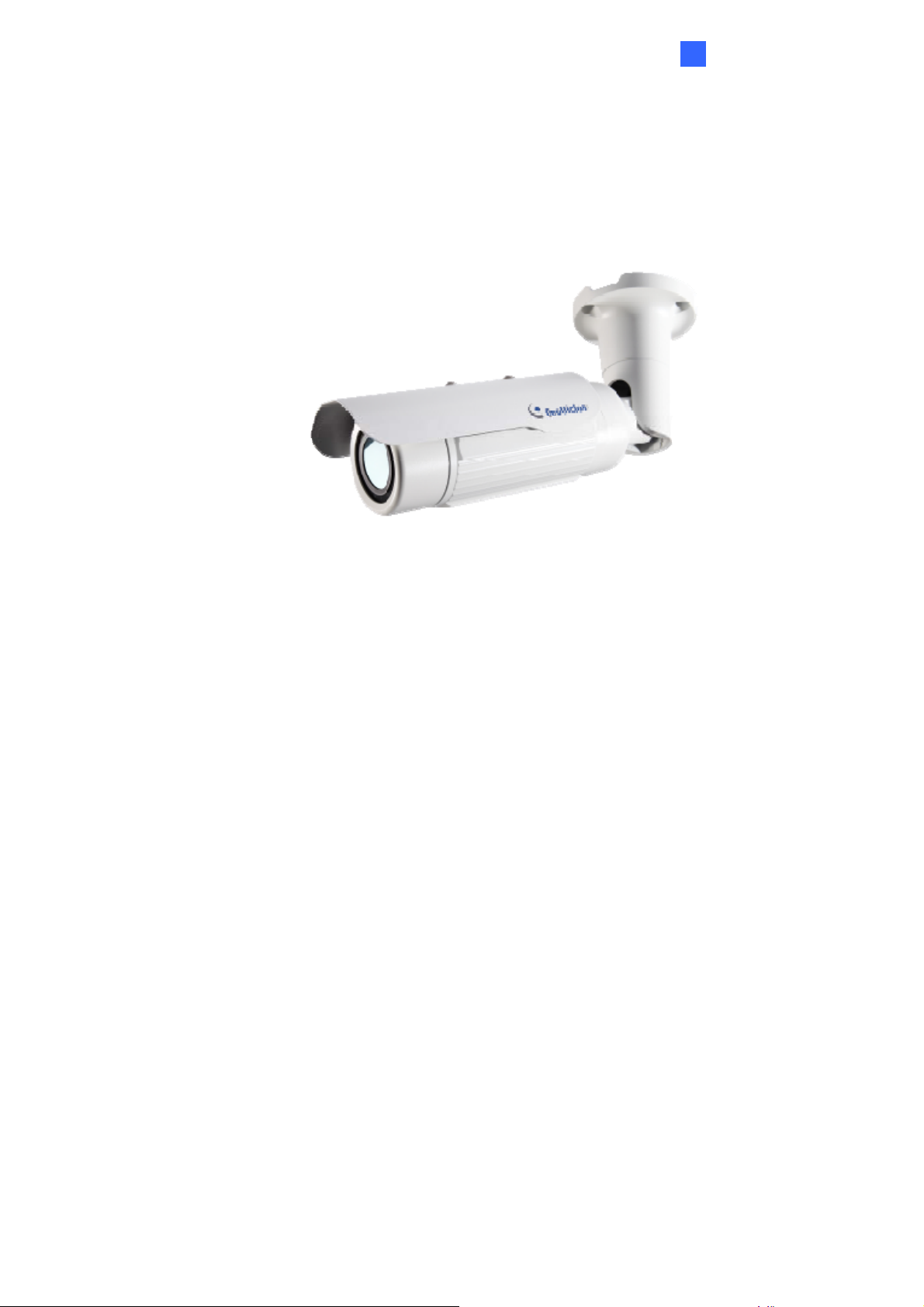
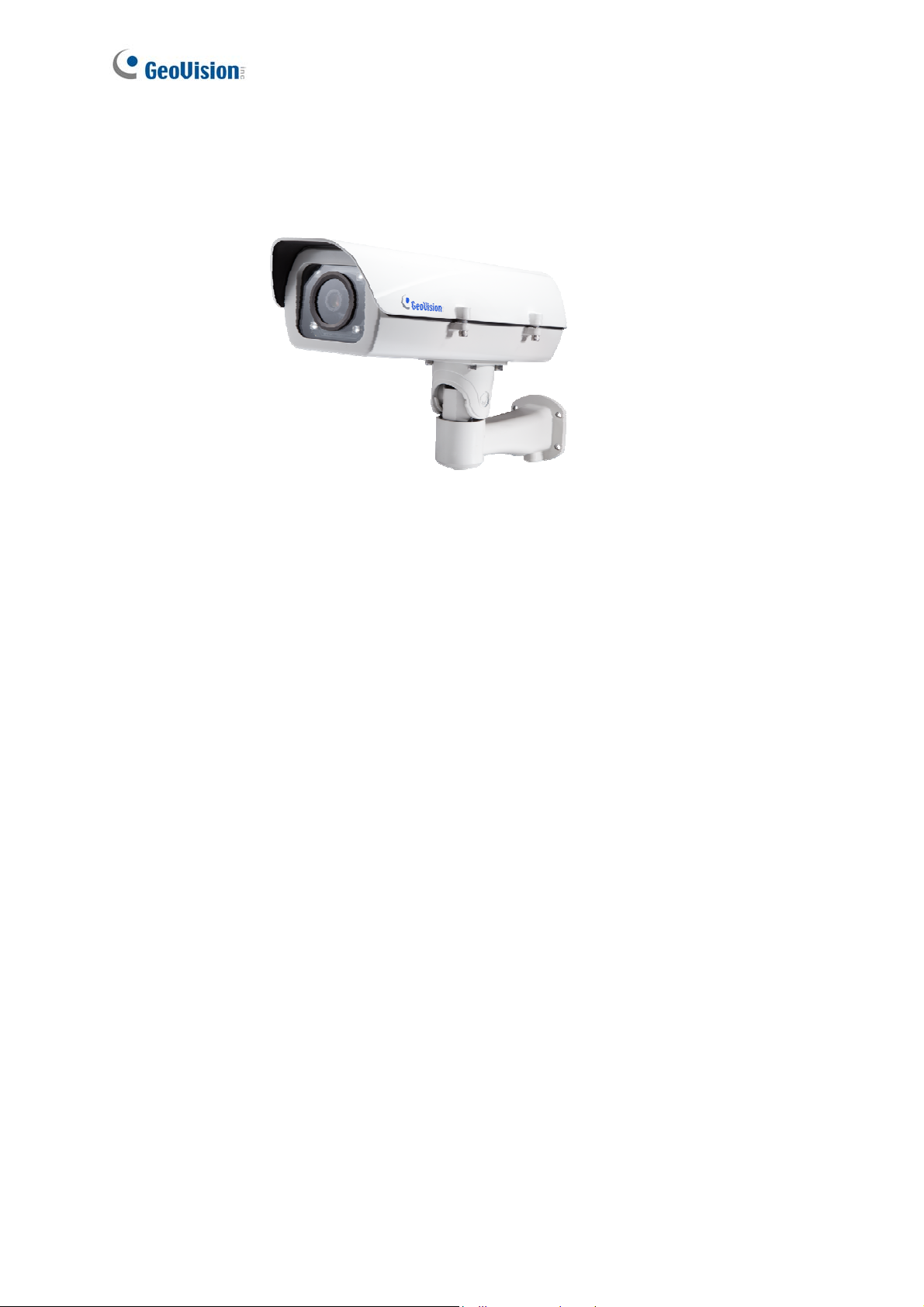
1.1 GV-IP LPR Camera 5R
Introduction
1
Ideal for parking lot installation, the GV-IP LPR Camera 5R is a 1.3 MP B/W network camera
designed for recognition of reflective license plates on vehicles traveling at 60 km/h (37 mph)
or less. With its multiple LEDs and intelligent IR, the camera is able to automatically adjust its
shutter speed to the scene and produce clear license plate capture under low-light conditions.
The motorized varifocal lens take the advantage of its motorized focus / zoom in that the user
can remotely adjust the focus and zoom through the Web interface. It is weather proof (IP67)
and also able to work in environments with temperatures ranging from -20°C (-4°F) to 50°C
(122°F).
The GV-IP LPR Camera 5R can be easily configured through its Web interface and you can
record and play back recordings using the free GV-NVR software included in the standard
package.
1
Page 13

1.1.1 Features
˙ 1/3” B/W progressive scan CMOS
˙ Motorized varifocal lens for remote focus / zoom adjustment
˙ Dual streams from MJPEG or H.264
˙ Up to 30 fps at 1280 x 1024
˙ Maximum speed 60 km/h (37 mph)
˙ Recognition for reflective license plate only
˙ Ingress protection (IP67)
˙ Vandal resistance (IK10)
˙ Maximum IR distance 5 M (16.4 ft)
˙ Built-in fan
˙ Defog
˙ Motion detection
˙ Privacy mask
˙ Text overlay
˙ IP address filtering
˙ Power supplied through PoE (PoE+, IEEE 802.3 at)
˙ Support for iPhone, iPad, Android and 3GPP
˙ ONVIF (Profile S) conformant
˙ 30 languages on Web interface
2
Page 14

Introduction
1
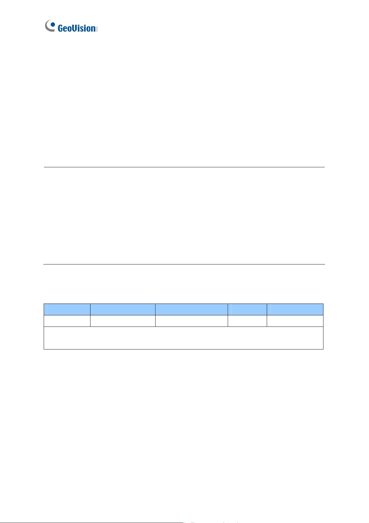
1.1.2 System Requirements
To access the camera functions and settings through Web browser, ensure your PC is in good
network connection and use one of the following Web browsers:
Microsoft Internet Explorer 7.x or later
Google Chrome
Mozilla Firefox
Safari
Microsoft Edge
Note:
1. For users of Internet Explorer 8 or later, additional settings are required. For details,
see Appendix C.
2. With non-IE browsers,
A. Motion Detection, Text Overlay and two-way audio are not supported.
B. The Play function is only available on the live view window (Figure 3-2).
C. RTSP streaming must be kept as enabled. For more details, see 4.3.6 RTSP.
Compatible Software Version
Model Firmware Version GV-System Version GV-VMS GV-ASManager
V1.00 V8.5.8.0 N/A V4.2 GV-IR LPR
Camera 5R
V1.01 V8.5.9.0 or later V14.10 or
V4.22 or later
later
Note: The License Plate Recognition function is only supported by GV-VMS LPR V15.10 or
later.
3
Page 15

1.1.3 Packing List
˙ GV-IP LPR Camera 5R
˙ Self Tapping Screw x 3
˙ Plastic Screw Anchor x 3
˙ Torx Wrench x 2
˙ Sun-Shield Cover Kit (1 Sun-Shield Cover, 2 Philips Head Screws,
2 Plastic Screw Spacers and 2 Hexagon Screws included)
˙ Silica Gel Bag
˙ GV-IP LPR Camera Software CD
˙ GV-NVR Software DVD
˙ GV-ASManager Software DVD
˙ Warranty Card
4
Page 16
Introduction
1
1.1.4 Device Installation
1.1.4.1 Installation Guidelines
To produce quality image and to avoid software recognition errors, make sure you adhere to the
guidelines when installing your GV-IP LPR Camera 5R. See GV-LPR Camera Installation Guide.
1.1.4.2 Installing the Camera
After you have read through the installation guides and chosen an installation site, follow the
steps below to install the GV-IP LPR Camera 5R.
1. Mark the installation site and drill three holes for screw anchors.
2. Insert the supplied screw anchors.
3. Secure the camera to the wall using the supplied screws.
Figure 1-1
4. Remove the protection sticker from the camera’s cover.
5. Connect the camera to the network and supply power via the PoE cable. See 1.1.5
Connecting the Camera.
6. Access the live view. See Getting Started, Chapter 2.
7. Based on the live view, adjust the angle, zoom and focus of the camera of the camera. For
adjusting three shafts, see 1.1.6 Adjusting the Angles.
Figure 3-4 in 3.3 The Control Panel of the Live View Window.
8. Install the sun-shield cover to the camera. For details, see 1.1.8 Installing the Sun-Shield Cover.
For changing zoom and focus, see
5
Page 17
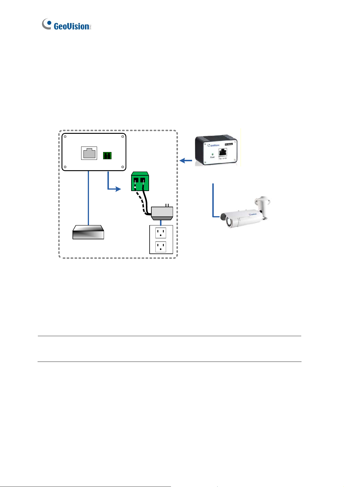
1.1.5 Connecting the Camera
It is suggested to use GV-PA191 PoE Adapter to connect the GV-IP LPR Camera 5R to the
network. Follow the steps below for connection.
1. Connect the camera’s cable to the GV-PA191 PoE Adapter as illustrated below. The
power and network will be supplied simultaneously.
Rear Panel
LAN 10/100
Ethernet
Cable
Hub/Router
Powe r IN
Power
(-)(+)
GV-PA191 PoE Adapter
PoE
GV-IP LPR Camera 5R
Figure 1-2
2. When the Power LED on the front panel of the GV-PA191 PoE Adapter turns green, you
are ready to access the live view, adjust the image clarity and configure the basics. See
Getting Started, Chapter 2.
Note: The GV-PA191 PoE Adapter (AC Power Adapter included) can be purchased upon
request.
6
Page 18
Introduction
1
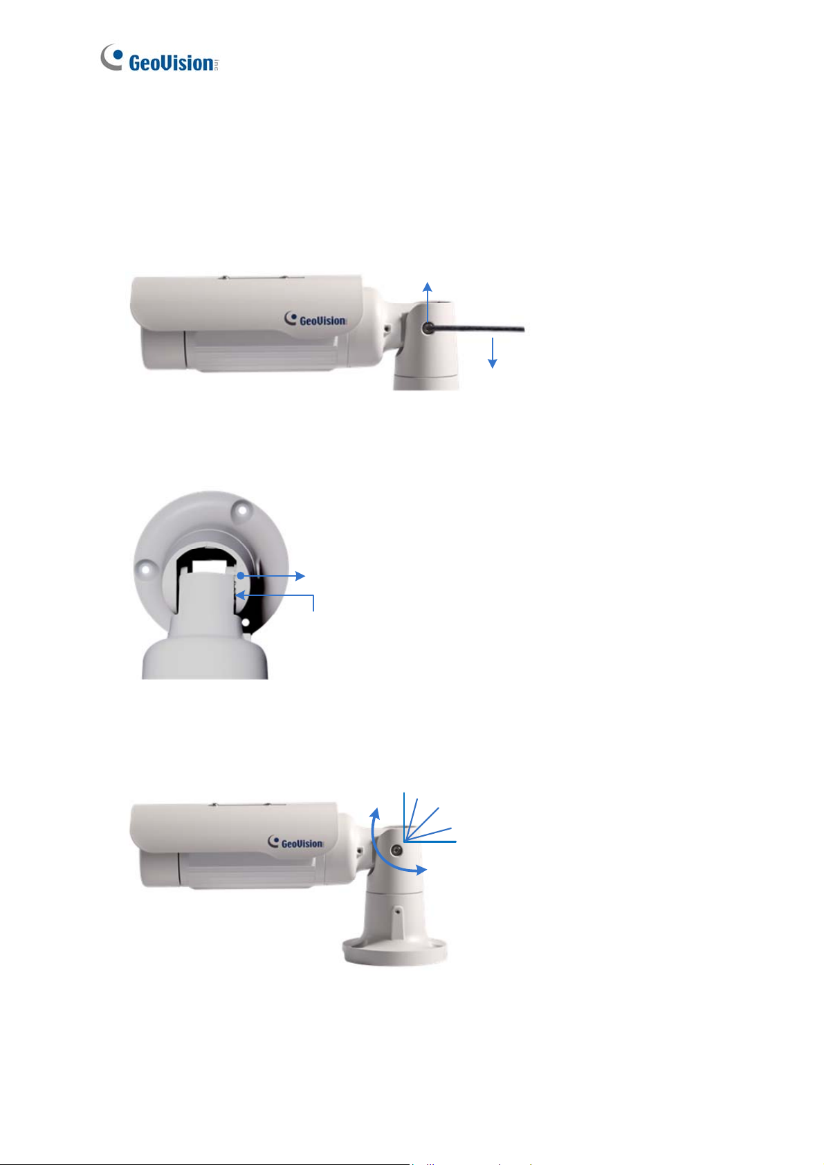
1.1.6 Adjusting the Angles
The GV-IP LPR Camera 5R is designed to be adjustable in three shafts for easy and flexible
installation.
First Shaft
You can adjust the camera body by 360 degrees to the right or the left.
1. Unscrew the panning lock screw with the torx wrench.
Panning Lock Screw
Torx Wrench
Figure 1-3
2. Adjust the angle of camera body to the right or the left, and fasten the panning lock screw.
0 ~ 360°
Figure 1-4
7
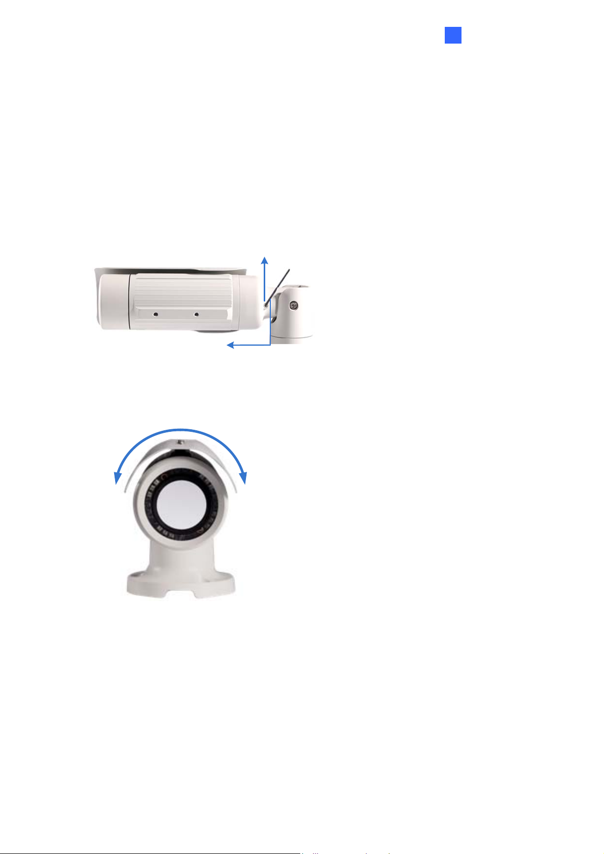
Page 19
Second Shaft
You can adjust the camera body up and down by 90, 112.5, 135, 157.5 or 180 degrees by
using the gears inside the camera body and the camera base.
1. Unscrew the tilting lock screw with the torx wrench.
Tilting Lock Screw
Torx Wrench
Figure 1-5
2. Hold the camera body, and move the camera base to the right to separate the camera
gears.
Move the Camera
Base to the Right
Camera Gears
Camera Body
Figure 1-6
3. Adjust the angle of camera body to 90°, 112.5°, 135°, 157.5° or 180°. Then move the
camera base to the left to combine the gears.
Figure 1-7
4. Fasten the tilting lock screw.
8
180
°
157.5°
135 °
112.5°
90°
Page 20
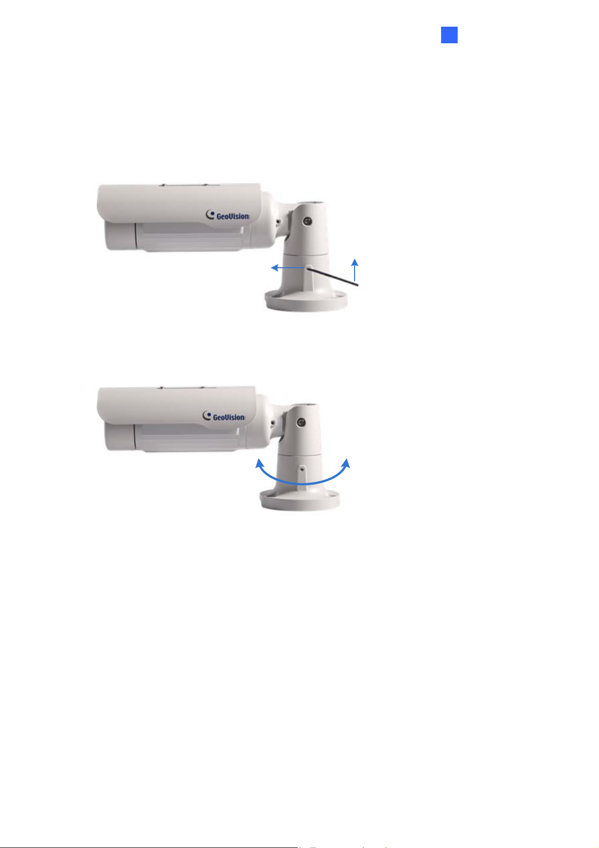
Third Shaft
You can adjust the camera base by 360°.
1. Unscrew the base fixing screw with the torx wrench.
Torx Wrench
Base Fixing Screw
Introduction
1
Figure 1-8
2. Adjust the angle of camera base, and fasten the base fixing screw.
0~360°
Figure 1-9
9
Page 21
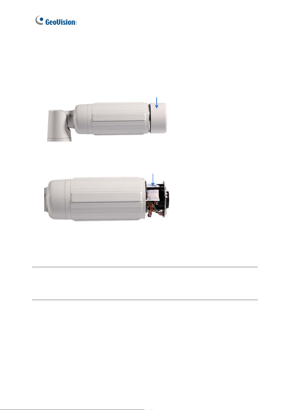
1.1.7 Replacing the Silica Gel Bag
Once the cover of GV-IP LPR Camera 5R is opened, you must replace the original silica gel
bag with a new one.
1. Loosen the camera’s cover.
Camera’s Cover
Figure 1-10
2. Remove the silica gel bag.
Silica Gel Bag
Figure 1-11
3. Insert a new silica gel bag to the camera module and fasten the camera’s cover within 2
minutes of opening the silica gel bag package.
IMPORTANT: The silica gel loses its effectiveness when the dry ca mera is op ened. To
prevent the lens from fogging up, re place the silica gel bag every time when you o pen the
camera and conceal the gel bag in the camera within two minutes of exposing to the open air.
10
Page 22
Introduction
1
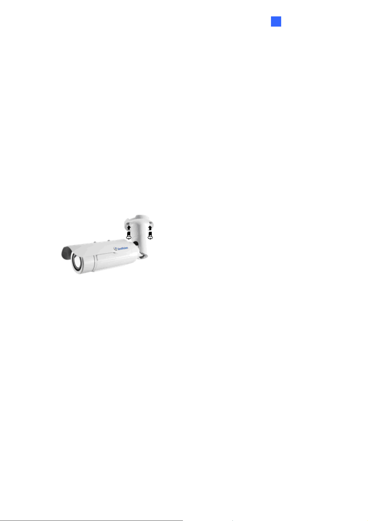
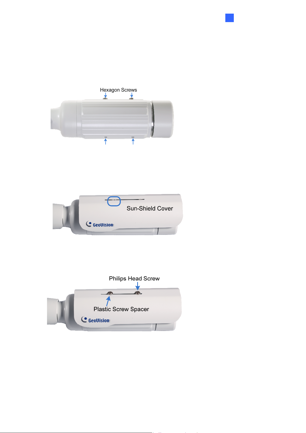
1.1.8 Installing the Sun-Shield Cover
After setting up the Bullet Camera, now you can install the sun-shield cover to the camera.
1. Fasten the hexagon screws either on top or below the camera.
Figure 1-12
2. Put the sun-shield cover on top of hexagon screws. Make sure to aim the rear hexagon
screw at the edge of the sun-shield cover’s aperture for optimal sun-shield performance.
Figure 1-13
3. Fasten the Philips head screws with the plastic screw spacers.
Figure 1-14
11
Page 23
1.2 GV-LPC1100
The GV-LPC1100 is a 1.3 MP B/W network camera designed for recognition of reflective
license plates on vehicles traveling at 120 km/h (75 mph) or less. With its multiple LEDs and
intelligent IR, the camera is able to automatically adjust its shutter speed to the scene and
produce clear license plate capture for one lane under low-light conditions. The motorized
varifocal lens take the advantage of its motorized focus / zoom in that the user can remotely
adjust the focus and zoom through the Web interface. It is weather proof (IP67) and also able
to work in environments with temperatures ranging from -40°C (-40°F) to 50°C (122°F).
The GV-LPC1100 can be easily configured through its Web interface and you can record and
play back recordings using the free GV-NVR software included in the standard package.
12
Page 24

1.2.1 Features
˙ 1/3” B/W progressive scan CMOS
˙ Motorized varifocal lens for remote focus / zoom adjustment
˙ Dual streams from MJPEG or H.264
˙ Up to 30 fps at 1280 x 1024
˙ Maximum speed 120 km/h (75 mph)
˙ Recognition for reflective license plate only
˙ Ingress protection (IP67)
˙ Vandal resistance (IK10)
˙ Maximum IR distance 10 m (32.8 ft)
˙ DC 48V, High PoE (PoE++, 120 W)
Introduction
1
˙ Built-in heater and fan
˙ Support for TV-out
˙ Support for I/O (1 in / 1 out)
˙ Two-way audio
˙ Defog
˙ Motion detection
˙ Privacy mask
˙ Text overlay
˙ IP address filtering
˙ Support for iPhone, iPad, Android and 3GPP
˙ ONVIF (Profile S) conformant
˙ 30 languages on Web interface
13
Page 25
1.2.2 System Requirements
To access the camera functions and settings through Web browser, ensure your PC is in good
network connection and use one of the following Web browsers:
Microsoft Internet Explorer 7.x or later
Google Chrome
Mozilla Firefox
Safari
Microsoft Edge
Note:
1. For users of Internet Explorer 8 or later, additional settings are required. For details,
see Appendix C.
2. With non-IE browsers,
A. Motion Detection, Text Overlay and two-way audio are not supported.
B. The Play function is only available on the live view window (Figure 3-2).
C. RTSP streaming must be kept as enabled. For more details, see 4.3.6 RTSP.
Compatible Software Version
Model Firmware Version GV-System Version GV-VMS GV-ASManager
GV-LPC1100 V1.01 V8.5.9.0 + Patch V14.10 V4.23
Note: The License Plate Recognition function is only supported by GV-VMS LPR V15.10 or
later.
14
Page 26
1.2.3 Packing List
˙ The GV-LPC1100 camera
˙ Screw Anchor x 4
˙ Screw x 4
˙ Washer x 4
˙ Torx Wrench
˙ GV-PA482 PoE Adapter
˙ Power Adapter (DC 48V, 2.5A, 120 W)
Introduction
1
˙ AC Power Cord
˙ Silica Gel Bag
˙ Adhesive tape for Silica Gel Bag
˙ GV-IP LPR Camera Software CD
˙ GV-NVR Software DVD
˙ GV-ASManager Software DVD
˙ GV-LPR Camera Installation Guide
˙ Warranty Card
15
Page 27
1.2.4 Device Installation
1.2.4.1 Installation Guidelines
To produce quality image and to avoid software recognition errors, make sure you adhere to the
guidelines when installing your GV-LPC1100. See GV-LPR Camera Installation Guide.
1.2.4.2 Installing the Camera
After you have read through the installation guides and chosen an installation site, follow the
steps below to install the GV-LPC1100.
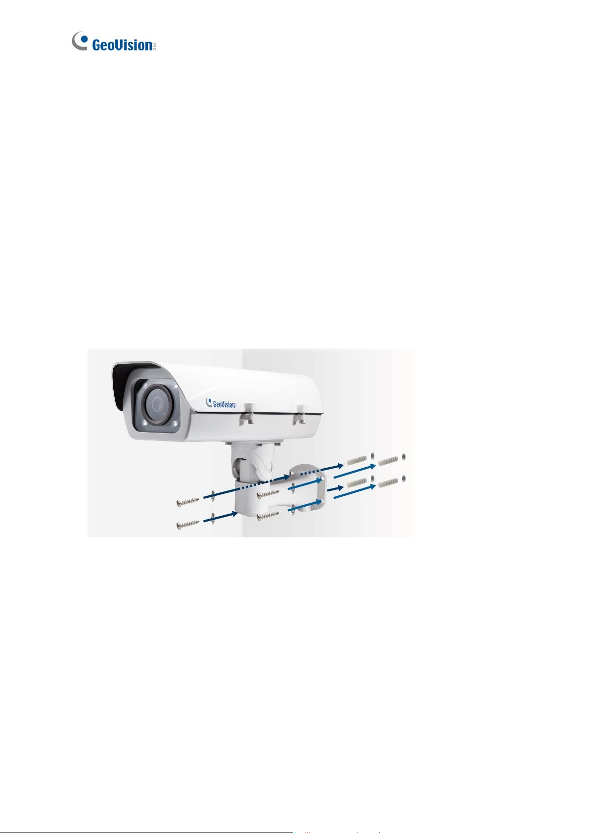
1. Mark the installation site and drill four holes for screw anchors.
2. Insert the supplied screw anchors.
3. Secure the camera to the wall using the supplied screws.
Figure 1-15
4. Connect the camera for power and network connection. See 1.2.5 Connecting the Camera.
5. Access the live view. See Getting Started, Chapter 2.
16
Page 28
Introduction
1
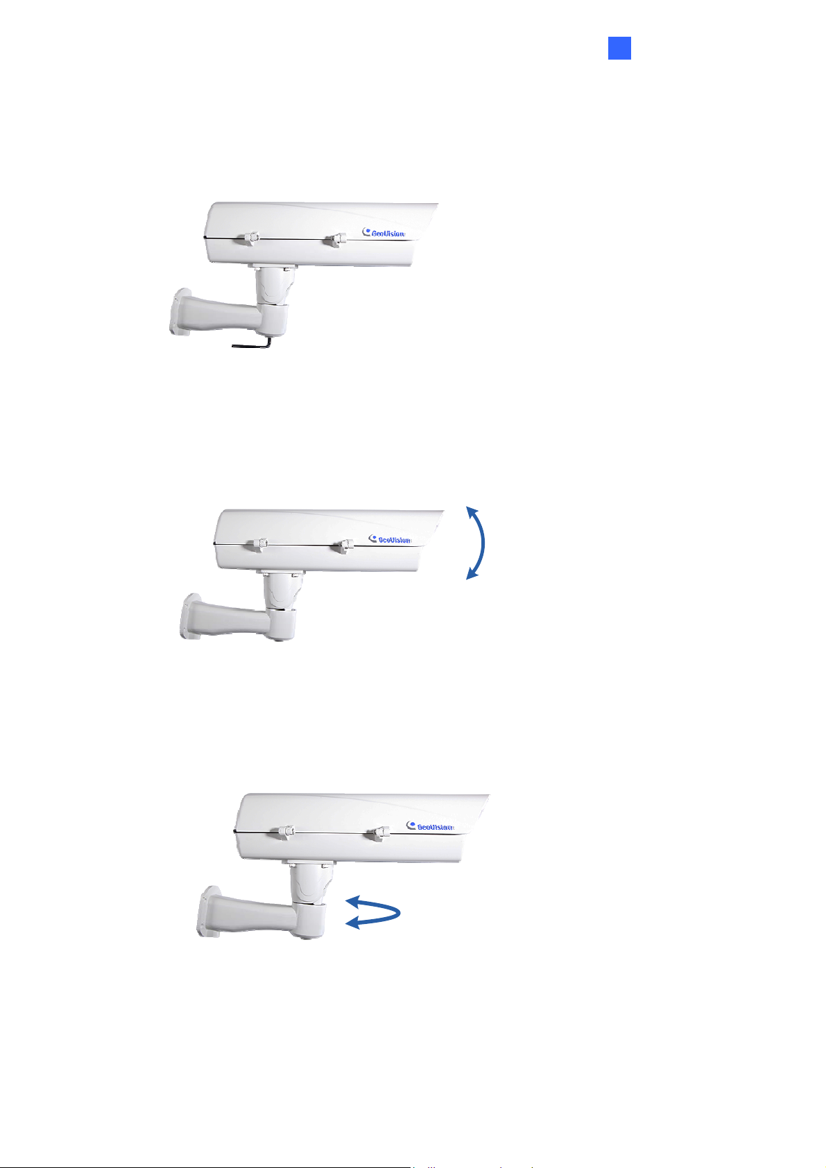
6. Based on the live view, adjust the angle, zoom and focus of the camera. Loosen the indicated
screw with the supplied torx wretch and adjust the joint.
Figure 1-16
Tilt Adjustment
Pan Adjustment
Figure 1-17
Figure 1-18
17
Page 29
1.2.5 Connecting the Camera
GV-IP LPR Camera supports two power specifications: DC 48V, High PoE (120 W).
Follow the steps below to connect your GV-LPC1100 to power, network and other wires
needed.
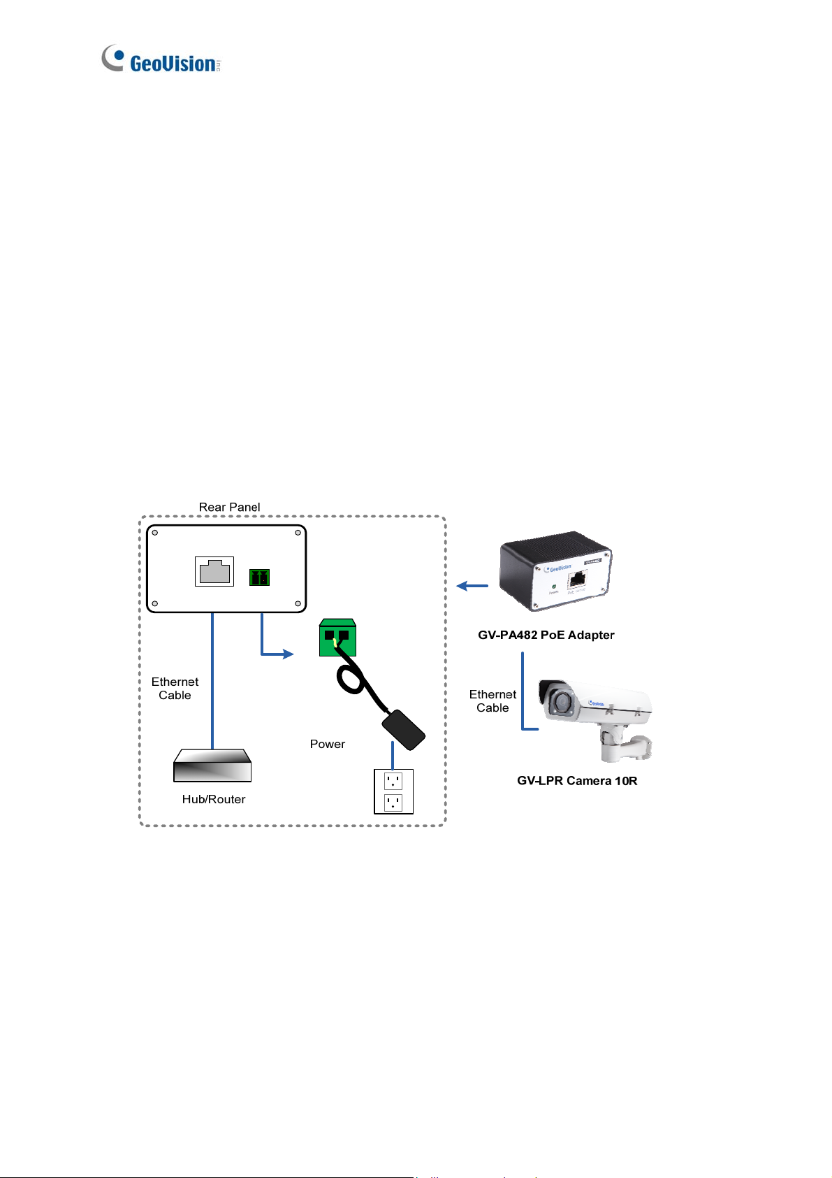
1.2.5.1 PoE Connection
Use the supplied GV-PA482 PoE Adapter to connect the camera to the power and network at
the same time. Two Ethernet cables are required for the connection.
1. Inset one end of the Ethernet cable into the PoE 10/100 port on the GV-PA482. Connect
the other end of the cable to your camera.
2. Insert one end of the Ethernet cable into the LAN 10/100 port on the GV-PA482. Connect
the other end of the cable to the hub or router connecting to your computer.
LAN 10/1 00
Power IN
Figure 1-19
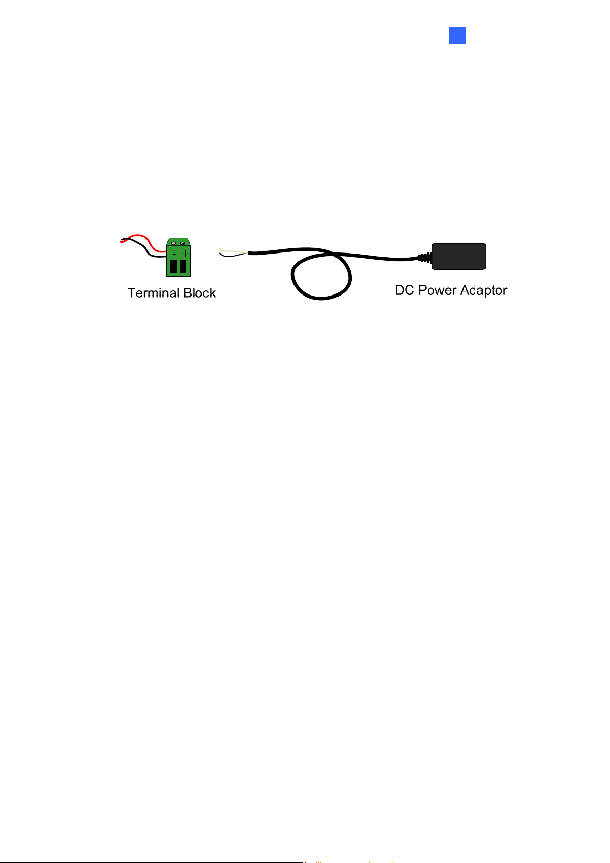
3. Insert the white wire of the supplied DC power adaptor into left-side pin of the terminal
block on the GV-PA482, and the black wire to the right-side pin.
4. Attach the AC power cord to the DC power adaptor.
5. Connect the AC power cord to the power outlet.
6. When the Power LED on the front panel of the GV-PA482 turns green, you are ready to
access the live view, adjust the image clarity and configure the basics. See Getting S t arted,
Chapter 2.
18
Page 30
Introduction
1
1.2.5.2 Power Adapter Connection
Besides PoE connection, you can use the supplied DC power adaptor, and connect the
camera to the power.
1. Plug the DC power adapter to the 2-pin terminal block on the camera by inserting the
wire with white lines to the (+) pin and the black wire to the (-) pin.
Figure 1-20
2. Attach the AC power cord to the DC power adaptor.
3. Connect the AC power cord to a power source.
19
Page 31

1.2.5.3 Wire Definition
Figure 1-21
Camera
Wire Definition
RJ-45 Ethernet
Black BNC TV out
Green RCA Audio Out
Pink RCA Audio In
Brown Digital Output
Yellow Digital Input
White GND
2-Pin Terminal Block Power
20
Page 32

Introduction
1
1.2.6 Replacing the Silica Gel Bag
Once the housing of GV-LPC1100 is opened, you must replace the original silica gel bag with
a new one.
1. Loose the screws holding the camera’s lid with the torx wrench.
Figure 1-22
2. Open the camera’s lid and you will find a silica gel bag attached to the interior of the lid.
Silica Gel Bag
Figure 1-23
3. Remove the silica gel bag and place a new bag back to its original position.
4. Fasten the camera’s lid within 2 minutes of replacing the silica gel bag.
IMPORTANT:
1. The silica gel loses its effectiveness when the dry camera is opened. To prevent the lens
from fogging up, replace the silica gel bag every time when you open the camera and
conceal the gel bag in the camera within two minutes of exposing to the open air.
2. GV-LPC1100 currently does not support recording to Micro SD card or Mini USB
function.
21
Page 33

1.3 GV-LPC1200 / LPR1200
The camera is a 1 MP B/W network camera designed for recognition of reflective license
plates on vehicles traveling at 200 km/h (124.27 mph) or less. With its multiple high-power
LEDs and intelligent IR, the camera is able to automatically adjust its shutter speed to the
scene and produce clear license plate capture for one lane under low-light conditions. The
motorized varifocal lens take the advantage of its motorized focus / zoom in that you can
remotely adjust the focus and zoom through the Web interface. It is weather proof (IP67) and
also able to work in environments with temperatures ranging from -40°C (-40°F) to 50°C
(122°F).
GV-LPR1200 is also capable of recognizing the license plate numbers with the built-in LPR
processor, comparing captured license plates with the database downloaded from the access
control software GV-ASManager, and opening a gate or barrier when there is a match.
The camera can be easily configured through its Web interface and you can record and play
back recordings using the free GV-NVR software included in the standard package.
22
Page 34

1.3.1 Features
˙ Megapixel B/W progressive scan CCD
˙ Motorized varifocal lens for remote focus / zoom adjustment
˙ Dual streams from MJPEG or H.264
˙ Up to 30 fps at 1280 x 720
˙ Maximum speed 200 km/h (124.27 mph)
˙ Recognition for reflective license plate only
˙ Ingress protection (IP67)
˙ Vandal resistance (IK10 for metal casing)
˙ Maximum IR distance 20 m (65.6 ft)
˙ Built-in LPR processor to perform recognition (for GV-LPR1200 only)
Introduction
1
˙ Built-in heater and fan
˙ Support for TV-out
˙ Support for I/O (2 in / 2 out)
˙ 10x optical zoom
˙ Two-way audio
˙ Recognized plate numbers export (for GV-LPR1200 only)
˙ Defog
˙ Motion detection
˙ Text overlay
˙ IP address filtering
˙ Support for iPhone, iPad, Android and 3GPP
˙ ONVIF (Profile S) conformant
˙ 30 languages on Web interface
23
Page 35

1.3.2 System Requirements
To access the camera functions and settings through Web browser, ensure your PC is in good
network connection and use the following Web browser:
Microsoft Internet Explorer 7.x or later
Google Chrome
Mozilla Firefox
Safari
Microsoft Edge
Note:
1. For users of Internet Explorer 8 or later, additional settings are required. For details,
see Appendix C.
2. With non-IE browsers,
A. Motion Detection, Text Overlay and two-way audio are not supported.
B. The Play function is only available on the live view window (Figure 3-2).
C. RTSP streaming must be kept as enabled. For more details, see 4.3.6 RTSP.
Compatible Software Version
Compatible Software Version Model Firmware
Version
GV-System GV-VMS GV-ASManager
GV-LPC1200 V1.0
V8.6.2.0 + Patch V14.10 + Patch V4.3
GV-LPR1200
V1.01
Note: The License Plate Recognition function is only supported by GV-VMS LPR V15.10 or
later.
24
Page 36

1.3.3 Packing List
˙ The GV-LPC1200 / LPR1200 camera
˙ Screw Anchor x 4
˙ Screw x 4
˙ Washer x 4
Introduction
1
˙ Torx Wrench
˙ Power Adapter (DC 12V, 5A)
˙ AC Power Cord
˙ Silica Gel Bag
˙ Adhesive Tape for Silica Gel Bag
˙ GV-IP LPR Camera Software CD
˙ GV-NVR Software DVD
˙ GV-ASManager Software DVD
˙ GV-LPR Camera Installation Guide
˙ Warranty Card
25
Page 37

1.3.4 Installing the Camera
1.3.4.1 Installation Guidelines
To produce quality image and to avoid software recognition errors, make sure you adhere to the
guidelines when installing your camera. See GV-LPR Camera Installation Guide.
1.3.4.2 Installing the Camera
After you have read through the installation guide and chosen an installation site, follow the
steps below to install the camera.
1. Mark the installation site and drill four holes for screw anchors.
2. Insert the supplied screw anchors.
3. Secure the camera to the wall using the supplied screws.
Figure 1-24
4. Connect the camera for power and network connection. See 1.3.5 Connecting the Camera.
5. Access the live view. See Getting Started, Chapter 2.
26
Page 38

Introduction
1
6. Based on the live view, adjust the angle, zoom and focus of the camera. Loosen the indicated
screw with the supplied torx wretch and adjust the joint.
Figure 1-25
Tilt Adjustment
Pan Adjustment
Figure 1-26
Figure 1-27
27
Page 39

1.3.5 Connecting the Camera
Follow the steps below to connect your camera to power.
1. Use a mini-flathead screwdriver to push the orange button, plug the DC power adapter to
the 2-pin terminal block connected to the camera by inserting the wire with the white line
to the (+) pin and the black line to the (-) pin. Then release the push button.
DC 12V Power AdaptorTerminal Block
Figure 1-28
2. Attach the AC power cord to the DC power adaptor.
3. Connect the AC power cord to a power source.
Note: It may take longer for the camera to power on when under low temperature:
-20 ~ 0°C (-4°F ~ 32°F): about 20 minutes
-40 ~ -20°C (-40°F ~ 4°F): about 45 minutes
28
Page 40

1.3.5.3 Wire Definition
Introduction
1
Figure 1-29
Camera
Wire Definition
RJ-45 Ethernet
Black BNC TV out
Green RCA Audio Out
Pink RCA Audio In
Brown Digital Output 1
Yellow Digital Input 1
White GND
Orange Digital Output 2
Blue Digital Input 2
Green RS-485+ (for GV-LPR1200 only)
Gray RS-485- (for GV-LPR1200 only)
2-Pin Terminal Block Power
29
Page 41

1.3.6 Replacing the Silica Gel Bag
Once the housing of GV-LPC1200 / LPR1200 is opened, you must replace the original silica
gel bag with a new one.
1. Loose the screws holding the camera’s lid with the torx wrench.
Camera’s Lid
Figure 1-30
2. Open the camera’s lid and you will find a silica gel bag attached to the interior of the lid.
Silica Gel Bag
Figure 1-31
3. Remove the silica gel bag and place a new bag back to its original position.
4. Fasten the camera’s lid within 2 minutes of replacing the silica gel bag.
IMPORTANT: The silica gel loses its effectiveness when the dry camera is opened. To
prevent the lens from fogging up, replace the silica gel bag every time when you open the
camera and conceal the gel bag in the camera within two minutes of exposing to the open air.
30
Page 42

Introduction
1
1.3.7 Fitting the Battery
The camera includes a 3V lithium battery to provide power to the camera settings and
real-time clock circuitry.
Memory
Card
Slot
Battery
Figure 1-32
IMPORTANT:
1. Make sure the plastic insulation film under the battery is removed when you use the
camera for the first time.
2. It is recommended to replace the battery annually.
31
Page 43

1.3.8 Installing a Mini USB Cable
To use UMTS-compatible devices, you need to prepare a Mini USB-to-USB cable with the
size of the Mini USB end smaller than 1 cm for threading and install it into the camera. Follow
the steps for installation.
Camera’s bottom
1 cm
Mini USB end
Figure 1-33
1. Loose 2 screws to open the camera’s lid and 4 screws to remove the camera mount with
the torx wrench.
Camera Mount
Camera’s Lid
Figure 1-34
2. Rotate to remove the indicated cap and remove the plug.
Plug
Figure 1-35
32
Page 44

Introduction
1
3. Take out the conduit connector inside the housing. Remove and disintegrate the
connector. You should have 3 parts.
21 3
Figure 1-36
4. Make a side slit to part 1 with a cutter knife.
Figure 1-37
5. Thread the cable through part 3 and part 2, push the cable with the Mini USB end into
part 1, thread through the camera bottom and plug it to the Mini USB port on the circuit
board.
Mini USB
end
USB
end
Mini-USB Connector
Figure 1-38
33
Page 45

6. Re-install the connector and the cap (part 3) tightly to make sure the camera is
watertight.
Note: Fill the gap between the Mini USB-to-USB cable and the conduit connector to
waterproof the cable before securing the camera.
Figure 1-39
34
Page 46

1.4 GV-LPC2210
Introduction
1
GV-LPC2210 is a 2 MP color network camera designed for recognition of reflective license
plates on vehicles traveling up at 120 km/h (75 mph) or less. Equipped with a Super Low Lux
CMOS image sensor, the camera is capable of displaying a color live view at near darkness.
Its multiple high-power LEDs and build-in intelligent IR provide clear license plate for two
lanes under low-light conditions at a maximum IR distance of 20 m (65.6 ft.). The motorized
varifocal lens take the advantage of its motorized focus / zoom in that the user can remotely
adjust the focus and zoom through the Web interface. It is weather proof (IP67) and also able
to work in environments with temperatures ranging from -40°C (-40°F) to 50°C (122°F).
The GV-LPC2210 can be easily configured through its Web interface and you can record and
play back recordings using the free GV-NVR software included in the standard package.
35
Page 47

1.4.1 Features
˙ 1/2.8” Megapixel Progressive Scan super low lux CMOS
˙ Motorized varifocal lens for remote focus / zoom adjustment
˙ Dual streams from MJPEG or H.264
˙ Up to 30 fps at 1920 x 1080
˙ Maximum speed 120 km/h (75 mph)
˙ Recognition for reflective license plate only
˙ Ingress protection (IP67)
˙ Vandal resistance (IK10)
˙ Maximum IR distance 20 m (65.6 ft)
˙ DC 48V, AC 24V (optional), High PoE (PoE++, 120 W)
˙ Built-in heater and fan
˙ Support for TV-out
˙ Support for I/O (1 in / 1 out)
˙ Two-way audio
˙ Defog
˙ Motion detection
˙ Privacy mask
˙ Text overlay
˙ IP address filtering
˙ Support for iPhone, iPad, Android and 3GPP
˙ ONVIF (Profile S) conformant
˙ 31 languages on Web interface
36
Page 48

Introduction
1
1.4.2 System Requirements
To access the camera functions and settings through Web browser, ensure your PC is in good
network connection and use one of the following Web browsers:
Microsoft Internet Explorer 7.x or later
Google Chrome
Mozilla Firefox
Safari
Microsoft Edge
Note:
1. For users of Internet Explorer 8 or later, additional settings are required. For details,
see Appendix C.
2. For users of non-IE browsers, download GV-Web Viewer to access full functioning user
interface. For details, see 3.1 Accessing Your Surveillance Images.
Compatible Software Version
Model Firmware Version GV-System Version GV-VMS GV-ASManager
GV-LPC2210 V1.02 V8.6.2.0 + Patch V14.10 +
V4.35
Patch
Note: The License Plate Recognition function is only supported by GV-VMS LPR V15.10 or
later.
37
Page 49

1.4.3 Packing List
˙ The GV-LPC2210 camera
˙ Screw Anchor x 4
˙ Screw x 4
˙ Washer x 4
˙ Torx Wrench x 1
˙ Power Adapter (DC 48V, 2.5A, 120 W)
˙ AC Power Cord
˙ Silica Gel Bag
˙ Adhesive Tape for Silica Gel Bag
˙ GV-IP LPR Camera Software CD
˙ GV-NVR Software DVD
˙ GV-ASManager Software DVD
˙ GV-LPR Camera Installation Guide
˙ Warranty Card
38
Page 50

Introduction
1
1.4.4 Device Installation
1.4.4.1 Installation Guidelines
To produce quality image and to avoid software recognition errors, make sure you adhere to the
guidelines when installing your GV-LPC2210. See GV-LPR Camera Installation Guide.
1.4.4.2 Installing the Camera
After you have read through the installation guides and chosen an installation site, follow the
steps below to install the GV-LPC2210.
1. Mark the installation site and drill four holes for screw anchors.
2. Insert the supplied screw anchors.
3. Secure the camera to the wall using the supplied screws.
Figure 1-40
4. Connect the camera for power and network connection. See 1.2.5 Connecting the Camera.
5. Access the live view. See Getting Started, Chapter 2.
39
Page 51

6. Based on the live view, adjust the angle, zoom and focus of the camera. Loosen the indicated
screw with the supplied torx wretch and adjust the joint.
Figure 1-41
Tilt Adjustment
Pan Adjustment
Figure 1-42
Figure 1-43
40
Page 52

Introduction
1
1.4.5 Connecting the Camera
The GV-LPC2210 supports two power specifications: DC 48V, High PoE (120 W).
Follow the steps below to connect your GV-LPC2210 to power, network and other wires
needed.
1.4.5.1 PoE Connection
Use the GV-PA482 PoE Adapter to connect the camera to the power and network at the same
time. Two Ethernet cables are required for the connection. For details, see 1.2.5.1 PoE
Connection.
Note: Optionally purchasing GV PA482 PoE Adapter is required for applying PoE function .
1.4.5.2 Power Adapter Connection
Besides PoE connection, you can use the supplied DC power adaptor, and connect the
camera to the power. For details, see 1.2.5.2 Power Adapter Connection.
41
Page 53

1.4.5.3 Wire Definition
Figure 1-46
Camera
Wire Definition
RJ-45 Ethernet
Black BNC TV out
Green RCA Audio Out
Pink RCA Audio In
Brown Digital Output
Yellow Digital Input
White GND
2-Pin Terminal Block Power
42
Page 54

Introduction
1
1.4.6 Replacing the Silica Gel Bag
You may also open the camera to restore the factory default settings. Once the housing of
GV-LPC2210 is opened, you must replace the original silica gel bag with a new one.
1. Loose the screws holding the camera’s lid with the torx wrench.
Figure 1-47
2. Open the camera’s lid and you will find a silica gel bag attached to the interior of the lid.
Figure 1-48
3. Remove the silica gel bag and place a new bag back to its original position.
4. Fasten the camera’s lid within 2 minutes of replacing the silica gel bag.
IMPORTANT:
1. The silica gel loses its effectiveness when the dry camera is opened. To prevent the lens
from fogging up, replace the silica gel bag every time when you open the camera and
conceal the gel bag in the camera within two minutes of exposing to the open air.
2. GV-LPC2210 currently does not support recording to Micro SD card or Mini USB
function.
43
Page 55

1.5 GV-LPC2211/2011
GV-LPC2211
GV-LPC2211 is a 2 MP color network camera designed for recognition of reflective license
plates on vehicles traveling up at 120 km/h (75 mph) or less with extreme
temperatures (-30°C ~ 50°C / -22°F ~ 122°F) resistance. It is weather proof (IP67). Equipped
with a Super Low Lux CMOS image sensor, the camera is capable of displaying a color live
view at near darkness. Its multiple LEDs and build-in intelligent IR provide clear license plate
for two lanes under low-light conditions at a maximum IR distance of 20 m (65.6 ft.) The
motorized varifocal lens take the advantage of its motorized focus / zoom in that the user can
remotely adjust the focus and zoom through the Web interface. The camera also allows
automatic and precise control of exposure using its P iris, producing images with better clarity
and contrast.
GV-LPC2011
GV-LPC2011 is a 2 MP color network camera designed for recognition of reflective license
plates on vehicles traveling up at 60 km/h (37 mph) or less with extreme temperatures (-30°C
~ 50°C / -22°F ~ 122°F) resistance. It is weather proof (IP67). Equipped with a Super Low Lux
CMOS image sensor, the camera is capable of displaying a color live view at near darkness.
Its multiple LEDs and build-in intelligent IR provide clear license plate for two lanes under
low-light conditions at a maximum IR distance of 9 m (29.6 ft.). The motorized varifocal lens
take the advantage of its motorized focus / zoom in that the user can remotely adjust the focus
and zoom through the Web interface. The camera also allows automatic and precise control
of exposure using its P iris, producing images with better clarity and contrast.
The GV-LPC2211/2011 can be easily configured through its Web interface and you can record
and play back recordings using the free GV-NVR software included in the standard package.
44
Page 56

1.5.1 Features
GV-LPC2211
˙ 1/2.8” color progressive scan super low lux CMOS
˙ Motorized varifocal lens for remote focus / zoom adjustment
˙ Dual streams from MJPEG or H.264
˙ Up to 30 fps at 1920 x 1080
˙ Maximum speed 120 km/h (75 mph)
˙ Recognition for reflective License Plate only
˙ Intelligent IR
˙ Day and Night function (with removable IR-cut filter)
Introduction
1
˙ Megapixel lens
˙ Maximum IR distance 20 m (65.6 ft)
˙ P-iris lens for auto iris control
˙ Vandal resistance (IK10 for metal casing)
˙ Ingress prot
˙ DC 12V / Po
˙ Wide Dynamic Range (WDR)
˙ 3D noise deduction
˙ Defog
˙ Motion detection
˙ Privacy Mask
˙ Text overlay
˙ Tampering Alarm
˙ IP address filtering
ection (IP67
E (IEEE 802
)
.3af)
˙ Supports iPhone, iPad, Android & 3GPP
˙ ONVIF (Profile S) conformant
˙ 30 languages on Web interface
45
Page 57

GV-LPC2011
˙ 1/2.8” color progressive scan super low lux CMOS
˙ Motorized varifocal lens for remote focus / zoom adjustment
˙ Dual streams from MJPEG or H.264
˙ Up to 30 fps at 1920 x 1080
˙ Maximum speed 60 km/h (37 mph)
˙ Recognition for reflective License Plate only
˙ Intelligent IR
˙ Day and Night function (with removable IR-cut filter)
˙ Megapixel lens
˙ Maximum IR distance 9 m (29.6 ft)
˙ P-iris lens for auto iris control
˙ Vandal resistance (IK10 for metal casing)
˙ Ingress prot
˙ DC 12V / Po
˙ Wide Dynamic Range (WDR)
˙ 3D noise deduction
˙ Defog
˙ Motion detection
˙ Privacy Mask
˙ Text overlay
˙ Tampering Alarm
˙ IP address filtering
˙ Supports iPhone, iPad, Android & 3GPP
˙ ONVIF (Profile S) conformant
˙ 30 languages on Web interface
ection (IP67
E (IEEE 802
)
.3af)
46
Page 58

Introduction
1
1.5.2 System Requirements
To access the camera functions and settings through Web browser, ensure your PC is in good
network connection and use one of the following Web browsers:
Microsoft Internet Explorer 7.x or later
Google Chrome
Mozilla Firefox
Safari
Microsoft Edge
Note:
1. For users of Internet Explorer 8 or later, additional settings are required. For details,
see Appendix C.
2. For users of non-IE browsers, download GV-Web Viewer to access full functioning user
interface. For details, see 3.1 Accessing Your Surveillance Images.
Compatible Software Version
Model Firmware
Version
GV-LPC2211 / 2011 V1.0 V8.6.2.0 + Patch V14.10 +
GV-System
Version
GV-VMS GV-ASManager
V4.35
Patch
Note: The License Plate Recognition function is only supported by GV-VMS LPR V15.10 or
later.
47
Page 59

1.5.3 Packing List
GV-LPC2211/2011 Camera
Sun-Shield Cover
Screw for Supporting Rack x 3
Screw for Sun-shield Cover x 2
RJ45 Connector
Silica Gel Bag x 1
Screw Anchor x 3
Washer x 2
Terminal Block
Screw for Mounting Kit x 3
Nut for Mounting Kit x 3
Hex Wrench
GV-IP LPR Camera Software CD
GV-NVR Software DVD
GV-ASManager Software CD
GV-LPR Camera Installation Guide
Warranty Card
Note: Power adapter can be purchased upon request.
48
Page 60

Introduction
1
1.5.4 Device Installation
1.5.4.1 Installation Guidelines
To produce quality image and to avoid software recognition errors, make sure you adhere to the
guidelines when installing your GV-LPC2211/2011. See GV-LPR Camera Installation Guide.
1.5.4.2 Installing the Camera
1. Slide the sun-shield cover onto the top of the camera. You can also secure the sun
shield cover onto the back of the camera. Adjust the position of the cover before fully
securing the cover with the washer and the screw.
Figure 1-49
Figure 1-50
Note:
1. The GeoVision logo on the sun-shield cover should be closer to the front of the
camera.
2. There are two holes for the screws at the back of the camera. You only need to
fasten one screw to secure the sun shield cover.
49
Page 61

2. Thread the Ethernet cable into the camera.
A. Remove the plug from the conduit connector.
Figure1-51
B. Disintegrate the removed conduit connector. Thread the Ethernet cable through
the 3 parts.
Figure 1-52
C. Assemble the conduit connector.
Figure1-53
50
Page 62

Introduction
1
3. Install the camera to the wall or ceiling using the screw anchors and screws for
supporting rack.
Figure1-54
4. Access the live view. See Getting Started, Chapter 2.
IMPORTANT: To avoid waterproofing failures, the top of the camera must be facing upward
for wall mount.
Figure 1-55
51
Page 63

1.5.4.3 Adjusting the Angles
The GV-LPC2211/2011 is designed to be adjustable in two shafts for easy and flexible
installation.
First Shaft
You can adjust the camera base by 360°.
1. Unscrew the base fixing screw with the torx wrench.
Figure 1-57
2. Adjust the angle of camera base, and fasten the base fixing screw with the torx wrench.
Figure 1-58
52
Page 64

Introduction
1
Second Shaft
You can adjust the camera body to the desired angle by tilting the camera module.
1. Unscrew the tilting lock screw with the torx wrench.
Figure 1-59
2. Adjust the angle of camera body to the desired angle.
Figure 1-60
3. Fasten the tilting lock screw.
53
Page 65

1.5.5 Connecting the Camera
The GV-LPC2211/2011 supports two power specifications: DC 48V, PoE (IEEE 802.3af).
Follow the steps below to connect your GV-LPC2211/20110 to power, network and other wires
needed.
1.5.5.1 PoE Connection
You can optionally purchase GV-PA191 PoE to connect the camera to the power and network
at the same time. Two Ethernet cables are required for the connection. For details, see 1.1.5
Connecting the Camera.
1.5.5.2 Power Adapter Connection
Besides PoE connection, you can use a DC power adaptor, and connect the camera to the
power. For details, see 1.2.5.2 Power Adapter Connection.
1.5.5.3 Wire Definition
The data cable provides connections for power, ground and network access. The wires are
defined below:
Figure 1-56
No. Wire Color Definition
1 Red DC 12V
2 Black Ground
3 Black (thick) PoE, Ethernet
54
Page 66

Introduction
1
1.5.6 Replacing the Silica Gel Bag
You may open the camera to load the factory default settings. Once the housing of
GV-LPC2211/2011 is opened, you must replace the original silica gel bag with a new one.
1. Remove the camera cover from the camera.
Figure 1-61
2. Loosen the camera’s screws and the hexagon pillars as indicated below.
3. Take out the camera from the camera body
Figure 1-62
55
Figure 1-63
Page 67

4. Cut the 2 silica gel bags apart with scissors and insert the new silica gel bags.
Figure 1-64
5. Secure the 2 hexagon pillars to the upper and lower holes of camera module as
indicated below.
Figure 1-65
6. Secure the camera cover.
Note:
1. The silica gel bag must be placed at the lower half of the camera body.
2. The silica gel loses its effectiveness when the dry camera is opened. To prevent the
lens from fogging up, replace the silica gel bag every time when you open the camera
and conceal the gel bag in the camera within two minutes of exposing to the open air.
56
Page 68

2
Getting Started
Chapter 2 Getting Started
2.1 Looking Up the IP Address
By default, your camera is assigned with an unused IP address by the DHCP server when the
camera is connected to the network. This IP address remains unchanged unless you unplug
or disconnect your camera from the network.
Note: If your router does not support DHCP, the default IP address will be 192.168.0.10. In
this case, it is strongly suggested to modify the IP address to avoid IP address conflict with
other GeoVision IP device on the same LAN. To change the IP address, see Changing the IP
Address later in this section.
Follow the steps below to find out the IP address of your camera:
1. Install the GV-IP Device Utility program from the Software DVD.
Note: The PC installed with GV-IP Device Utility must be under the same LAN with the
camera you wish to configure.
2. On the PC desktop, select Start, point to Programs and select GV IP Device Utility to
execute the program. The GV-IP Device Utility window appears and automatically
searches for the GV-IP devices on the same LAN.
Figure 2-1
57
Page 69

3. Click the Name or Mac Address column to sort.
Figure 2-2
4. Find the Mac Address of the camera, click its IP address and select Web Page.
Figure 2-3
5. The login page appears.
6. Type the default ID and password admin and click Apply to log in.
58
Page 70

2
Getting Started
2.2 Changing the IP Address
To modify the static IP address or set the camera to a public dynamic IP address, log in the
Web interface to access the network setting page.
1. Open your Web browser, and type in the IP address.
For static network connection, type the default IP address http://192.168.0.10
For DHCP connection, follow steps in 2.1 Looking Up the IP Address to look up the
current IP address.
2. In both Login and Password fields, type the default value admin. Click Apply.
3. In the left menu, select Network and then LAN to begin the network settings. This page
appears.
Figure 2-4
4. Select Static IP address or PPPoE and type the required network information.
5. Click Apply. The camera is now accessible by entering the assigned IP address on the
Web browser.
IMPORTANT:
1. If your camera uses a public dynamic IP address via PPPoE, use the dynamic DNS
Service to obtain a domain name linked to the camera’s changing IP address first. For
details on Dynamic IP Address and PPPoE, see 4.7.2 Advanced TCP/IP and 4.6.1 LAN
Configuration.
2. If PPPoE is enabled and you cannot access the camera, you may have to reset it to the
factory default and then perform the network settings again. To restore the factory
settings, see 5.3 Restoring to Factory Default Settings.
59
Page 71

2.2 Configuring the Basics
Once you have installed and logged in the camera, you are ready to configure some of its
primary settings through the Web interface:
Date and time adjustment: see 4.7.1 Date and Time Settings.
Login and privileged passwords: see 4.7.3 User Account.
Network gateway: see 4.5 Network.
Camera image adjustment: see 3.3 The Control Panel of the Live View Window.
Video format, resolution and frame rate: see 4.1.1 Video Setting.
60
Page 72

Chapter 3 Accessing the Camera
3
Accessing the Camera
This section introduces the features of the Live View window for you to acc
o types of user levels are allowed to log in the camera: Administrator and Gu
Tw
Administrator has full ac
live view and network status.
cess to all system configurations while the Guest can only access the
3.1 Accessing Your Surveillance Images
Follow these steps to a
1. Open a Web browser.
2. Enter the IP address or d
browser. To look up the IP address, see 2.1 Looking Up the IP Address.
ccess your surveillance images:
omain name of the camera in the Location/Address field of your
ess the camera.
est. The
Figure 3-1
3. Enter the login name and password.
The default login name and password for Administrator are admin.
The default login name and password for Guest are guest.
4. The live view web page is now displayed on your browser.
For Internet Explorer, the live view page is similar to the image in Figure 3-3-2.
61
Page 73

For Mozilla Firefox, Google Chrome, Safari, or Microsoft Edge, the live
view page is
similar to the image in Figure 3-3-1. Click GV-Web Viewer, type in
the IP address of
your camera, and click Connect to access the full functioning user interface.
Figure 3-2-1
Note: To enable the updating of images in Microsoft Internet Explorer, you must set your
browser to allow ActiveX Controls and perform a once-only installation of GeoVision’s
ActiveX component onto your computer.
62
Page 74

3
Accessing the Camera
3.2 The Live View Window
In the left menu, click Live View, and select Camera to see the live video.
8 11
10
9
1 2 3 4
5 6 7
Figure 3-2-2
No. Name Function
1 Play o. Plays live vide
2 Stop Stops playing video.
Talks to the surveillanc
3 one
Microph
4 Speaker
5 Snapshot
6 File Save
function is not available for G
GV-LPC2211/2011.
Listens to the audio ar
available for GV-IP LPR Camera 5R and GV-LPC2211/2011.
Takes a snapshot of live video.
--- See 3.4 Snapshot of a Live Video.
Records live video to the local computer.
--- See 3.5 Video Recording.
e area from the local computer. Note this
V-IP LPR Camera 5R and
ound the camera. Note this function is not
63
Page 75

No. Name Function
7 Full Screen
Show System
8
Menu
9 PTZ Control
Switches to full screen view. Right-click the ima
options: Snapshot, Full Screen, Resolution, PIP
--- See 3.6 Picture-in-Picture and Picture-and-
Brings up
these functions: Alarm Notify, Video and Audio
Configuration, Remote Config, Show Camera Na
ge to have these
and PAP.
Picture View.
me and
Image Enhance.
--- See 3.7 Alarm Notification, 3.8 Video
3.9 Remote Configuration, 3.10 Camera N
Digital PTZ, 3.12 Image Enhancement respective
and Audio Configuration,
ame Display, 3.11
ly.
Enables the PTZ Control Panel or the Visual PTZ. The
performable functions are Zoom In / Out, Foc
Auto Focus.
Note the Auto Focus function only works for GV-IP
5R and GV-LPC1100 while other LPR came
automatically foc
us.
Enables the I/O Control Panel or the Visual Auto
us In / Out, and
LPR Camera
ra models can
mation. Note this
10 I/O Control
11 Recognition Result
function is only supp
orted by cameras with I/O function.
--- See 3.12 I/O Control.
Displays the snapshots of the recognition results when the
camera recognizes a license plate. Note this function is only
supported by GV-LPR1200.
64
Page 76

3
Accessing the Camera
3.3 The Control Panel of the Live View Window
To open the control panel of the Live View window, click the arrow button on top
You
can access the following functions by using the right and left arrow buttons on the control
p
anel.
of the viewer.
Click this button to select
from a drop-down menu
Click this arrow button to
open the control panel
Arrow buttons
Figure 3-3
[Information] Displays the version of the camera, local time of the local computer
camera, the number of users logging in to the camera and the OCX regis
[Video] Displays the current v
ideo codec, resolution and data rate.
tration path.
[Audio] Note this function is only supported by cameras with audio function. D
audio data rates when the microphone and speaker devices are enabled.
, time of the
isplays the
[I/O Control] Note this function is only supported by cameras with I/O function. Provides a
real-time graphic display of the input and output status. You can force the output to be
triggered by double-clicking its icon.
[Alarm Notify] Displays the captured images by motion detection. For this function to work,
you must configure the Alarm Notify settings first. See 3.7 Alarm Notification.
65
Page 77

[Camera Adjustment] Adjusts the image quality settings. Click Save to store the changes to
the settings.
GV era 5R /
-IP LPR Cam GV-L G
GV-LPC1100
PC1200 /
GV-LPR1200
V-LPC2210 / 2211 /
2011
Figure 3-4
66
Page 78

Brightness: Adjusts the brightness of the image.
3
Accessing the Camera
Contrast: Adjusts the relative differences between one pixel and the nex
Saturation: Adjusts th
GV-LPC221
Sharpness: Adjusts the sharpness of the image.
Gamma: Adjusts the relative proportions of bright and dark areas.
Auto Exposure Reference: Adjusts the exposure of the image. Note thi
0 / 2211 / 2011.
e saturation of the image. Note this function is only available for
only available for GV-LPC1200, GV-LPR1200 and GV-LPC2210 / 2211 / 201
White balance: The camera automatically adjusts the color to be closes
you are viewing. You can choose one of the four p
Fluorescent. You can also choose Manual to adjust the white balan
resets: Auto, Outdoor, Indoor, and
ce manually. Note
this function is only available for GV-LPC2210 / 2211 / 2011.
Flicker less: The camera automatically matches the frequency of your
image to the frequency of indoor light sources, e.g. fluo
rescent lighting. You can also
select 50 Hz or 60 Hz manually. If these don’t match, faint light and dark
appear in your images. Check the power utility to de
termine which frequency is used.
Note this function is only available for GV-LPC2210 / 2211 / 2011.
t.
s
function is
1.
t to the image
camera’
s
bars may
Image Orientation: Adjusts the orientation of image by selecting Normal
, Horizont
Mirror, Vertical Flip and Rotate 180 on the Live View window.
Slowest Shutter Speed: Sets the shutter speed. Shutter speed co
of the lights enters the image sensor and directly im
p ure that creates a brighter
resentation. A slow shutter speed allows higher light expos
acts the quality of image
p
overall image by blurring moving objects and bringing out backgr
faster shutter speed lowers color and image clarity in order to
ntrols the amount
ound details, and a
capture motions.
The minimum shutter speed ranges from 1/500 to 1/8000 sec.
GV-IP LPR Camera 5R, GV
GV-LPR1200, GV-LPC1200 / 2211 / 2210 / 2011, from 1/120 to 1/
-LPC1
100, from 1/250 t
Select Auto for automatic shutter control or select a shutter speed va
Maximum Video Gain: Changes the maximum gain level. Note this function is on
available for GV
D/N: Note this function is only available for GV-LPC2210 / 2211 / 2011. Select Auto
-LPR1200 and GV-LPC1200 / 2210 / 2211 / 2011.
o 1/2000
sec.
2000.
lue.
ly
for automatic switch between day mode and night mode depending on the amount of
al
light detected. Select Black and white to switch the camera to night mode. Select
Color to switch the camera to day mode. The value 10 is the most light-sensitive. Only
for GV-LPC 2210, select Trigger by Input to switch between day mode and night
67
Page 79

mode once the input device (e.g. sensor or button) is triggered. See the same D/N
s
etting in D/
Denoise: Reduces image noise especially under low-light cond
N, Special V
denoise value, the stro
ideo Settings, 4.1.1.1 Streaming 1/2.
itions.
The higher the
nger the effect. Note this function is only available for
GV-LPC2210 / 2211 / 2011.
Defog: Select Auto to automatically enhance the visibility of images. Select
disable the functi
Zoom: Click the Zoom In and Zoom Out buttons to adjust
on.
the apparent
distance of the scene.
Focus Change: Click the Focus In and Focus Out buttons to
focus. To focus automatically, click the Focus Mode
Focus Mode: Select Normal Scan, Regional Scan or Full Scan and
Start
focuses the cam
on the live view.
button to automatically adjust the camera focus. The N
era the fastest. The Regional Scan mode focuses the area selected
The Full Scan mode performs a detailed checkup and
button.
best focus. Note this function is only available for GV-IP LPR Camera 5R
adjust the
then click the
ormal Scan mode
applies the
and
GV-LPC1100 / 2210.
Close to
Day Night Focus: Note this function is only available for GV-LPC2210 / 221
Saves focus settings for day mode and nigh
To configure fixed settings for day mode and night mode, select Manual
t mode. Select Auto to automatically focus.
and follow the
steps below:
Make sure the D/N is in Auto mode for the best effect. The follow
setting will be ap
Adjust the focus using the Focus In
plied to
the current D/N mode.
and Focus Out
ing focus
bu
ttons and/or the
Focus Mode function.
Click Day Mode Save
or the Night Mode Save
button d
epending on
the current D/N mode.
Metering: Controls th
e camera’s exposure. Select Normal for the camera to adjust
exposure based on the full live view. Select Regional Metering for the camera to
adjust exposure of specified zones. Draw directly on the live view and a
with “AE (automatic exposure)” app
the block, right-click the block and select Delete
ears. You can establish up to 4 zones. To remove
. Note this function is only available for
block marked
GV-LPC2210 / 2211 / 2011.
1 / 201
1.
[Internal Temperature] Shows the current internal temperature of the camera and the normal
temperature range.
[Download] Allows you to install programs from the hard drive.
68
Page 80

3.4 Snapshot of a Live Video
To take a snapshot of live video, follow these steps:
3
Accessing the Camera
1. Click the Snapshot button (No. 5, Figure 3-2). The Save As dialog box ap
2. Specify Save in, ty
may also choose to display the camera name and/or the da
quality for the snapshot.
3. Click the Save button to save the image in the local computer.
Note: You can also obtain a snapshot of the live view without logging in the user interface by
executing the CGI command. See Appendix A.
pe the File name, and select JPEG or BMP for Save as Type. You
te, the text color and image
pears.
3.5 Video Recording
You can record live video for a certain period of time to your local computer.
1. Click the File Save button (No. 6, Figure 3-2). The Save As dialog box appears.
2. Specify Save in, type the File name, and move the Time Period scroll bar to specify the
time length of the video clip from 1 to 5 minutes.
3. Click the Save button to start recording.
4. To stop recording, click the Stop button (No. 2, Figure 3-2).
69
Page 81

3.6 Picture-in-Picture and Picture-and-Picture View
The Live View window provides two types of close-up views: Picture-in-Picture
Picture-and Pictu
the surveillance area.
Picture-in-Picture View
W
ith the Picture-in-Picture (PIP) view, you can crop the video to get a close-up view or zoom
in on the video.
re (PAP). The two views are useful to provide clear and detailed images of
(PIP) and
Navigation box
Inset window
Figure 3-5
1. Right-click the live view and select PIP. An inset window appears.
2. Click the insert
3. Move the navigation box around in the inset window t
selected area.
4. To adjust the navigation box size, move the cursor to any of the box corners, and enlarge
or diminish the box.
5. To exit the PIP view, right-click the image and click PIP again.
window. A navigation box appears.
o have a close-up view of the
70
Page 82

3
Accessing the Camera
Picture-and-Picture View
With the Picture-and-Picture (PAP) view, you can create a split video effect with multiple
close-up views on the image. A total of 7 close-up views can be defined.
Figure 3-6
1. Right-click t
he live view and select PAP. A row of three inset wind
ows appears at the
bottom.
2. Draw a navig
one inset window. Up to seven navigation boxes can be drawn o
3. To adjust a navigation box size, move the cursor to any of the box corners,
ation box on the image, and this selected area is immediately reflected in
n the image.
and enlarge or
diminish the box.
4. To move a navigation box to another area on the image, drag it to that are
5. To add, display/hide or to change the frame color of the navigation boxes
live view, select
Enable Add-Focus-Area Mode: Allows the user to ad
Mega Pixel Setting and click one of these options:
d navigation boxes to the
a.
, right-click the
image.
Display Focus Area of PAP Mode: Displays or hides the navigation boxes on the
image
Set Color of Focus Area: Changes the color of the box frames.
6. To delete a navigation box, right-click the desired box, select Focus Area of PAP Mode
and click Delete.
7. To exit the PAP view, right-click the image and click PAP again.
71
Page 83

3.7 Alarm Notification
When a motion
is detected, you can be alerted by a pop-up live video and view up to four
captured images.
Pop-up live video Captured images
Figure 3-7
T
o configure
this function, click the Show System Menu button (No. 8, Figure 3-2), and select
Alarm Notify. This dialog box appears.
Figure 3-8
Motion Notify: Once motion is detected, the captured images are displayed on the
control panel of the Live View window.
I/O Alarm Notify: Once the input device is triggered, the captured images are display
on the control panel of the Live View window. F
needs to install the input device properly. See 4.2.1 Input Setting. Note this function is only
available for cameras with I/O function.
Alert Sound: Activates the computer alarm on motion.
Auto Snapshot: The snapshot of live video is taken every 5 seconds on motion.
File Path: Assigns a file path to save the snapshots.
72
or this funct
ion to work, the Administrator
ed
Page 84

3.8 Video and Audio Configuration
3
Accessing the Camera
You can enable the microphone and speaker f
or two-way audio communication and adjust the
set the number of frames to keep for live view buffer.
Click the Sh
Configurati
r of frames to keep in live view buffer. Keeping more frames for
Camera: Sets the numbe
ow System Menu button (No. 8, Figure 3-2), and select Video and Audio
o
n.
live view buffer can ensure a smooth live view, but the live view will be delayed for the
number of seconds specified.
Figure 3-9
Audio Configure: You can enable the microphone and speaker and adjust the audio
volume. Note this setting is not available for GV-IP LPR Camera 5R and GV-LPC2211 /
2011.
Figure 3-10
73
Page 85

3.9 Remote Configuration
You can upgrade the device firmware over the network. Click the Show
(No. 8, Figure 3-2), and select Remote Config. The Remote Config dialog box will appear.
[Firmware Upgrade] In this tab, you can upgrade the firmware over the network. For details,
see Chapter 5 Advanced Applications.
3.10 Camera Name Disp
To display the camera name on the image, click the Show System Menu button (No. 8,
Figure 3-2), and select Show Camera Name.
lay
Syste
m Menu button
3.11 Image Enhancement
To enhance the image quality of live video, click the Show System Menu button (No. 8,
Figure 3-2), and select Image Enhance. This dialog box appears.
Figure 3-11
De-Interlace: Covert the interlaced video into non-interlaced video.
De-Block: Remove the block-like artifacts from low-quality and highly compressed video.
Enable DirectDraw: Activate the DirectDraw function.
74
Page 86

3.12 Digital PTZ
3
Accessing the Camera
Digital PTZ allows non-PTZ cameras to sim
ulate PTZ movements on live view. Note this
function is only supported by GV-LPC2211 / 2011.
1. Click live view and select Digital PTZ.
Figure 3-12
2. To zoom in / out, move the cursor to the control panel at left corner and click the
corresponding buttons. To bring the view back to its default image, click Home.
3. To adjust the view, zoom the image first and then click
to move your camera up, down,
left, right, left up, left down, right up or right down.
Zoom In
Zoom Out
Home
Not Functional
Figure 3-13
Note: The Focus In / Out and the speed level are not functional for Digital PTZ.
75
Page 87

3.13 I/O Control
Note this function is only supported by cameras with I/O function. The I
provides a real-time graphic display of camera status, I/O st
atus, and alarm events.
Additionally, you can remotely force output to be triggered.
/O ˇControl window
Figure 3-14
To display the I/O control window, click the I/O Control button (No. 11, Figure 3-2) and
select I/O Control.
The Alarm List is displayed in three levels. The first level indicates date, the second
indicates time, and the third indicates alarm ID. Clicking the Reset button will clear the list.
To trigger an output device, highlight an output and then click the Output button.
76
Page 88

3.14 Visual Automation
3
Accessing the Camera
Note this function is only supported by cameras with I/O function. The Visual Au
allows you to change the current state of the electronic device by simply clic
e.g. turning the light ON. This feature is only available when the V
isual Automation is set
king on its image,
ahead by the Administrator. For details, see 4.1.5 Visual Automation.
tomation
Figure 3-15
To access this feature, click the
I/O Control button (No. 10, Figure 3-2) and select Visual
Automation.
To change the style of the set areas, click the gr
will have these options:
Show All: Displays all set areas.
Rect Float: Embosses all set areas.
Set Color: Changes the frame color of all set areas
een
I/O button on the top left corner.
You
77
Page 89

Chapter 4 Administrator Mode
The Administrator can access and configure your camera over the network. The configuration
categories include: Video and Motion, Events and Alerts, Monitoring, Recording
Schedule, Network and Management.
78
Figure 4-1
Page 90

Corresponding Section for Configuration Menu
Find the topic of interest by referring to the indicated section.
4.1.1 V ideo Settings
4.1.2 Motion Detection / Detection Mode
4.1.3 Privacy Mask
4
Administrator Mode
4.1 V ideo and Motion
4.2 I/O Control
4.3 Event s and Alerts
4.1.4 T ext Overlay
4.1.5 T ampering Alarm
4.1.6 V isual Automation
4.1.7 Reco gnition Engine Settings
4.2.1 Input Settings
4.2.2 Output Settings
4.2.3 RS485
4.3.1 Email
4.3.2 FTP
4.3.3 Cent er V2
4.3.4 VSM (Vital Sign Monitor)
4.3.5 GV-Video Gateway / GV-Recording Server
4.3.6 R TSP
4.3.7 ONVIF
4.3.8 POS
4.3.9 Inquire Recognized Database
4.3.10 Re gistry Database
4.4 Monito ring 4.4.1 Monitoring Settings
4.5.1 I/O Monitor Settings
4.5 Sched ule
4.5.2 Reco gnizing Schedule Settings
4.6.1 LAN Configuration
4.6.2 Advanced TCP/IP
4.6 Network
4.6.3 UMTS
4.6.4 IP Filtering
4.6.5 SNMP Settings
4.7.1 Date and Time Settings
4.7.2 S torage Settings
4.7.3 User Account
4.7 Management
4.7.4 Log Information
4.7.5 T ools
4.7.6 Lang uage
79
Page 91

4.1 Video & Motion
The camera supports dual streams, Streaming 1 and Streaming 2, which allow separate
codec and resolutions settings for a single video transmission. In a bandwidth-limited network,
such as mobile phone surveillance, this dual-stream feature allows you to view live video in
lower resolution (Streaming 2), and record in highest resolution (Streaming 1) at the same
time.
Comparison between Stream 1 and Stream 2:
Video Setting Options Stream 1 Stream 2
Video Signal Type
Watermark Setting
Audio Codec
Video Entropy Coding
Setting
TV Out Setting
Status LED Control
Special View Setting
Note:
1. Watermark Setting is not available in GV-LPC2211 / 2011.
2. Special View Setting is only available in GV-LPC2210 / 2211 / 2011.
3. H264 Video Entropy Coding Setting is only available in GV-LPC2210.
Different codec, resolutions and frame rates can be applied to
Stream 1 and 2.
Not configurable. Settings in
Yes
Stream 1 will be automatically
applied to Stream 2.
80
Page 92

4.1.1 Video Settings
4.1.1.1 Streaming 1/2
4
Administrator Mode
Figure 4-2A
81
Page 93

Figure 4-2B
[Name]
Rename the camera. The camera name will appear on the Live View. To display the camera
name, see 3.10 Camera Name Display.
[Connection Template]
Select the type of your network connection. Unless you select Customized, this option will
automatically bring up the recommended video resolution, frame rate, bandwidth and GOP
size.
82
Page 94

4
Administrator Mode
[Video Signal Type]
Select the codec type, resolution and frame rate. Choose H.264 or MJPEG for the main
stream/sub stream. The supported resolutions are listed blow:
Default Codec
Models
Main Stream Sub Stream
GV-IP LPR Camera 5R
GV-LPC1100
MJPEG H.264
GV-LPC1200
GV-LPR1200
H.264 H.264
GV-LPC2210 / 2211 / 2011
Video Resolution for GV-IP LPR Camera 5R, GV-LPC1100
4:3 1280 x 960, 640 x 480, 320 x 240
Main Stream
16:9 1280 x 720, 640 x 360, 448 x 252
5:4 1280 x 1024, 640 x 512, 320 x 256
4:3 640 x 480, 320 x 240
Sub Stream
16:9 640 x 360, 448 x 252
5:4 640 x 512, 320 x 256
Video Resolution for GV-LPC1200 / GV-LPR1200
Main Stream 16:9 1280 x 720
Sub Stream 16:9 640 x 360
Video Resolution for GV-LPC2210
4:3 1600 x 1200, 1280 x 960, 640 x 480, 320 x 240
Main Stream
16:9 1920 x 1080, 1280 x 720, 640 x 360, 448 x 252
5:4 1280 x 1024, 640 x 512, 320 x 256
4:3 640 x 480, 320 x 240
Sub Stream
16:9 640 x 360, 448 x 252
5:4 640 x 512, 320 x 256
Video Resolution for GV-LPC2211 / 2011
Main Stream 16:9 1920 x 1080, 1280 x 720
Sub Stream 16:9 640 x 360
83
Page 95

[Bandwidth Management]
When using the H.264 codec, it is possible to configure the bitrate settings to control
bandwidth usage.
VBR (Variable Bitrate): The quality of the video stream is kept as constant as possible at
the cost of a varying bitrate. The bandwidth is much more efficiently used than a
comparable CBR. Set the image quality to one of the 5 standards: Standard, Fair, Good,
Great and Excellent.
Maximal Bit Rate: When the system bitrate exceeds the specified Maximal Bit Rate, the
system will automatically lower its bitrate so as not to exceed it. Select one of the bitrates
from the drop-down list or select Auto if you do not want to enable this function. The
default value is 6 MB
CBR (Constant Bitrate): CBR is used to achieve a specific bitrate by varying the quality
of the stream. The bitrates available for selection depend on the image resolution.
[GOP Structure and Length]
Set the maximum number of seconds between every key frame.
[H264 Video Entropy Coding Setting] Note this function is only available for GV-LPC2210.
By default, the entropy coding is set to CAVLC. To change it to CABAC, click and select from
the drop-down lost.
[Text Overlay Settings]
Overlaid with camera name: Includes camera names on live and recorded videos.
Overlaid with date stamps: Includes date stamps on live and recorded videos.
Overlaid with time stamps: Includes time stamps on live and recorded videos.
Overlaid with digital input description name: Includes the name of the selected input
on live and recorded videos. Note this function is not available for GV-IP LPR Camera
5R.
[Text Overlay Settings (OSD)] Note this function is only available for GV-LPC 2210 / 2211 /
2011. Displays camera name, date, and/or time on the live view and recorded videos when
viewing through GeoVision software and third-party software through ONVIF and RTSP.
Name: Type the camera name.
Font Size: Select the font size using the drop-down list.
84
Page 96

4
Administrator Mode
Overlay with: Select one or more of the options below to be overlaid on the live view and
recorded videos. Use the drop-down list to select the display position.
Camera Name
Date
System Time
[Watermark Setting]
Enable this option to watermark all recordings. The watermark allows you to verify whether
the video has been tampered while it was recorded. Note this function is not available in
GV-LPC2211 / 2011. See 5.4 Verifying Watermark.
[TV Out]
Select the signal format for the video output of the camera as either NTSC or PAL. This
function is disabled by default. Note this function is not available for GV-IP LPR Camera 5R
and GV-LPC2211 / 2011.
Note: For smooth live view display of GV-IP LPR Camera 5R / GV-LPC1100 on TV monitor,
the video resolution must be of 1280 x 1024 or lower. If dual streams are enabled, the sub
stream must be set to 640 x 480.
[LED Control]
Ready LED: Select Disable if you do not wish to use the Status LED. Note this function is
only available for GV-LPC1100 and GV-LPC2210 / 2211 / 2011.
[Special View Setting] Note this function is only available for GV-LPC2210 / 2211 / 2011..
D/N: Sets the sensitivity of day-night mode switch. The higher the sensitivity value, the
more sensitive the switch is from day mode to night mode. The default value is 5.
Auto: Select Auto for the camera to detect the amount of light present and
automatically switch to monochrome in a poorly-lit scene. Move the slider to adjust
the sensitivity level from 0 to 10.
Black and White: Select this option for the live view to be in monochrome.
Color: Select this option for the live view to be in color.
85
Page 97

Trigger by Input: This function is only supported by GV-LPC2210. Select this option
to switch between day mode and night mode once the input device (e.g. sensor or
button) is triggered.
BLC: Select On to enable Backlight Compensation (BLC). This function is used to adjust
the color intensity of scenes with strong light at the background.
IR Light: Select Auto for automatic switch between day mode and night mode
depending on the amount of light detected. Select Off to completely disable IR LEDs.
86
Page 98

4
Administrator Mode
4.1.1.2 Recognition Result
Note the function is only supported by GV-LPR1200. This function allows you to display the
recognized plate number, the date and time of recognition, or a desired text on the images of
the recognition results.
Figure 4-3A
Figure 4-3B
Overlay Logo on Recognition Results: Includes a desired text or description on
recognition results.
Overlay Time on Recognitions Results: Includes date stamps on recognition results.
Overlay LPR Result on Recognition Results: Includes the recognized plate number on
recognition results.
Overlay Text Position: Select a position from the drop-down list to overlay the text on
recognition results.
87
Page 99

4.1.2 Motion Detection / Detection Mode
4.1.2.1 GV-IP LPR Camera 5R / GV-LPC1100 / 1200 / 2210 / 2211 / 2011
Motion detection is used to generate an alarm whenever movement occurs within the scene.
You can configure up to 8 detection zones with different sensitivity values. Create at least one
detection zone to enable this function.
88
Figure 4-4a GV-IP LPR Camera 5R / GV-LPC1100 / GV-LPC2210
Page 100

4
Administrator Mode
Figure 4-4b GV-LPC2211 / 2011
Figure 4-4c GV-LPC1200
89
 Loading...