

Page 1
Elite
Page 2
ENGLISH
ELITE AUTOMATION
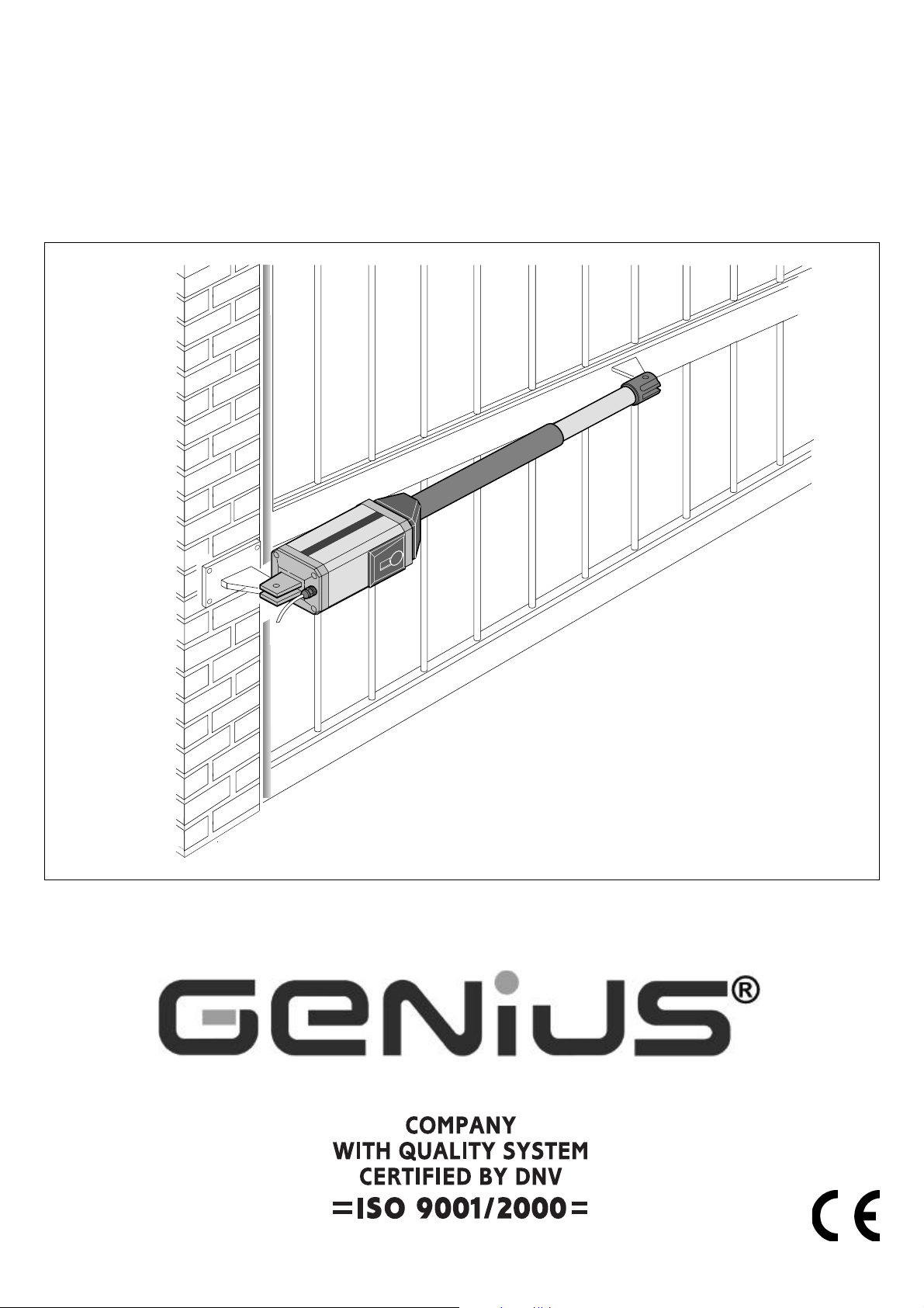
The ELITE automation system for swing gates comprises an
electromechanical operator which drives the gate leaves by
means of a worm screw.
The ELITE operator is irreversible and locks mechanically when the
motor is not in use. Therefore a lock does not need to be fitted.
Its manualoveride is activated by a customised key.
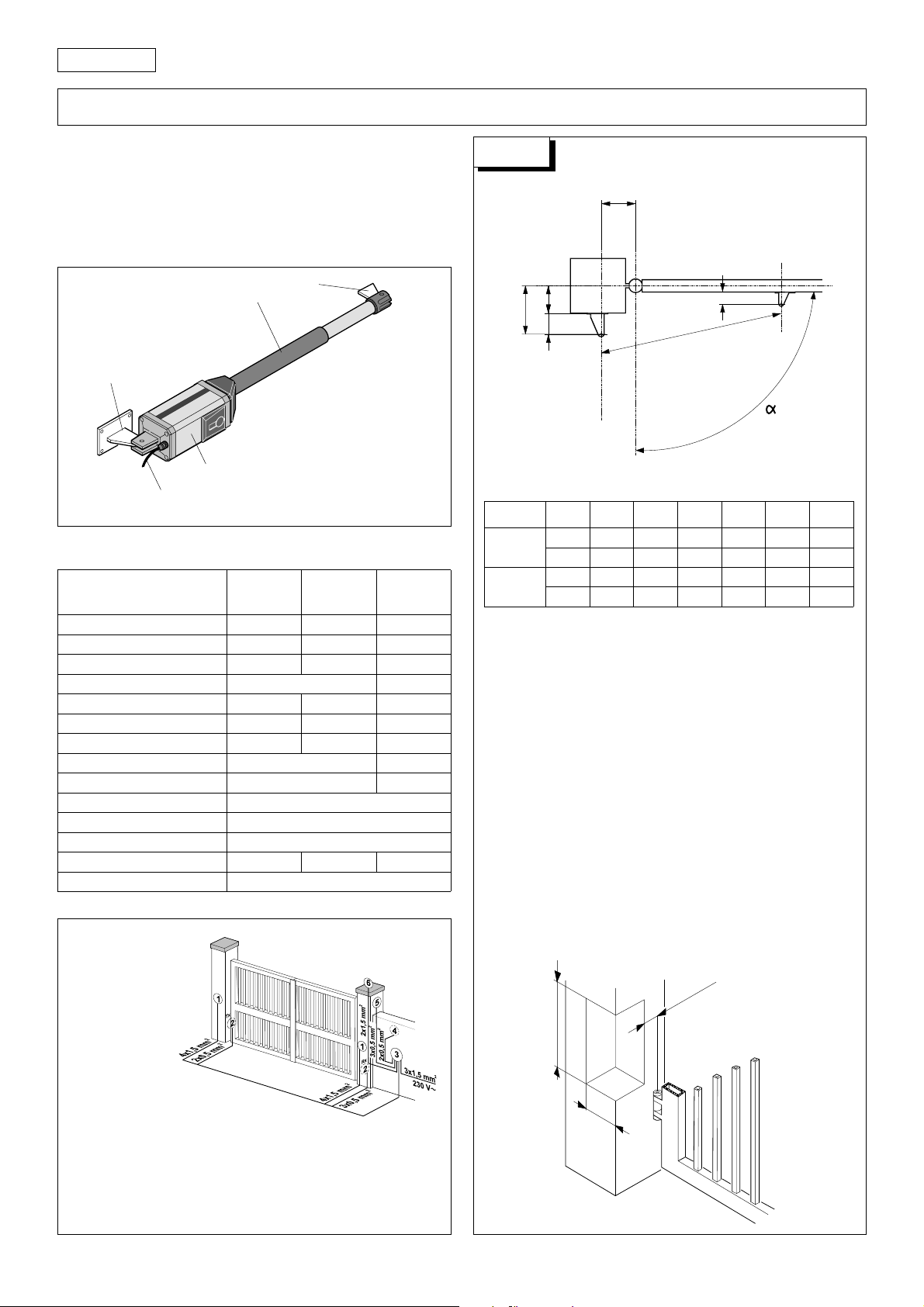
1. DESCRIPTION AND TECHNICAL SPECIFICATIONS
Fig. 1
4
3
5
1) Motor Unit
2) Power cable
1
2
Table 1:
Model
Power supply
Absorbed power
Current drawn
Electric motor rpm
Thermal cutout
Capacitor
Max. thrust/traction force
Rod stroke
Rod speed
Temperature range
Operator weight
Housing protection
Duty cycle (cycles/hour)
Maximum leaf length
Operator technical specifications
ELITE 300
ELITE 400
230V~ - 50Hz 230V~ - 50Hz
10 µF / 400V 8 µF / 400V
400 daN 320 daN300 daN
3) Worm screw
4) Front bracket
5) Rear bracket
ELITE 324
ELITE 424
24Vdc
350W 280W70W
1,5A 1,2A3A
1400 900
140°C 140°C
300 mm / 400 mm
1,6 cm/sec
-20°C +55°C
6,5 Kg
IP 44
20 2050
3 m / 4 m
ELITE
LENTO
400 mm
1,1 cm/sec
2. STANDARD INSTALLATION LAYOUT
Fig. 2
Drawing A
A
INSTALLATION DIMENSIONS
B
D
Z
L
45 min.
Fig. A
Table A: Recommended dimensions (in mm)
Model
300
400
(¹) useful rod stroke (²) max. dimension (³) min. dimension
αα
α
αα
90°
110°
90°
110°
A B C (¹) D (²) Z (³) L
145 145
125 125
195 195
165 165
290
290
390
390
70
50
120
90
45
45
45
45
970
970
1170
1170
CALCULATING INSTALLATION DIMENSIONS:
GENERAL RULES
If the dimensions specified in Table A cannot be used,
calculate different dimensions as follows:
- For 90° leaf opening: a + b = c
- For leaf opening over 90°: a + b < c
- The lower the dimensions of a and b the higher the
gate speed. Ensure that current standards are
observed.
- Make sure that the difference between a and b is
no more than 4 cm: larger differences cause large
variations in speed during opening and closing.
- Due to the dimensions of the operator, the minimum
value for Z is 45 mm (fig. A)
If the dimensions of the gate post or the position of
the hinge do not allow a to be kept within the
required value, make a recess in the gate post as
shown in fig. B.
1) Operators
2) Photocells
3) Control unit
4) Keyswitch
5) Receiver
6) Flashing light
Notes:1) Use suitable rigid/flexible pipes for laying power cables.
2) Always keep low voltage accessory cables separate from 230V~ power
cables. To avoid interference, use separate sheaths.
4
70 mm
200 mm
150 mm
Fig. B
Page 3
3. INSTALLATION OF THE AUTOMATION SYSTEM
3.1. PRELIMINARY CHECKS
To ensure trouble-free operation, make sure that the gate (whether
existing or to be installed) has the following specifications:
• max. length of each gate leaf: 3 metres (with operator with
300 mm stroke);
• maximum length of each gate leaf: 4 metres (with operator
with 400 mm stroke);
• strong and rigid leaf frame
• smooth movement of leaves during entire travel; no stiff points
• hinges in good condition
• mechanical travel limit stops present
• electric lock present in reversible version.
If any welding or brazing has to be done on the gate, this must
be done before installing the automation system.
Good condition of the structure is essential for reliability and
safety of the automation system.
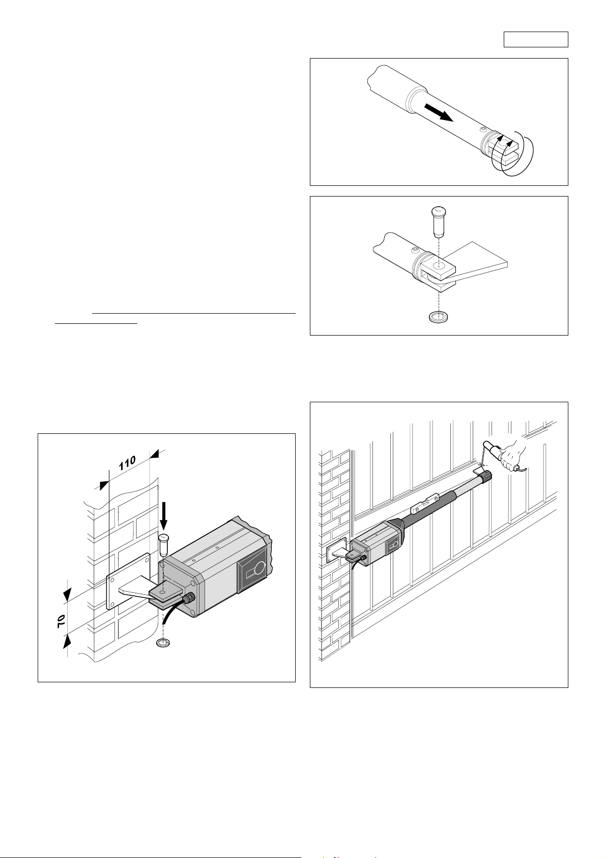
3.2. INSTALLATION OF THE OPERATORS
1) Fix the rear bracket to the gate post according to the
instructions in Table A. Adjust the length of the bracket if
necessary.
Warning:
operator operation.
In the case of iron gate posts, weld the bracket directly onto
the gate post.
In the case of brick/concrete gate posts, flush-mount a wall
plate (fig. 3), and weld the bracket to the plate.
2) Fix the operator to the rear bracket by means of the screws
supplied (fig. 3).
Observe the specified dimensions to ensure correct
ENGLISH
Fig. 4
Fig. 5
7) Fit the front bracket onto the rod as shown in fig. 5.
8) Close the gate leaf and, keeping the operator perfectly
horizontal, locate the leaf attachment position on the front
bracket (fig. 6).
Fig. 3
3) Release the operator (see paragraph 6).
4) Extend the rod to the end of its stroke (fig. 4).
5) Lock the operator (see paragraph 7).
6) Rotate the operator rod two full turns clockwise (fig. 4).
Fig. 6
9) Fix the front bracket temporarily to the leaf by two welds.
N.B.: If the gate frame does not allow for secure fixing of the
bracket, add a support plate.
10) Release the operator and ensure that the gate opens
smoothly with no stiff points and that it stops on the mechanical
travel stops.
5
Page 4

ENGLISH
11) Completely weld the front bracket to the leaf. When doing
this, detach the operator temporarily from the bracket to
prevent damage from welding scale.
N.B.:
1) Grease all pivots on brackets
2) If welding is not possible, the front and rear bracket plates
can be fixed using screws and screw anchors.
12) Attach the metal tag to the slot in the top section of the motor
in order to blank off the holes present as shown fig.7. On the
other hand, do not block the holes to be found in the lower
section.
1
2
3
4
5
Fig. 8
Fig. 7
13) Repeat the above operations to install the second operator,
if required.
14) Install the control unit box according to the dimensions given
in the relevant instructions.
4. STARTING THE AUTOMATED UNIT
1) Program the control unit according to your requirements as
described in the relevant instructions.
2) Power up the system and check the state of the LEDs
according to the table in the control unit instructions.
5. TESTING THE AUTOMATED UNIT
Carefully check operation of the operator and all
accessories connected to it.
Give the customer the page entitled "End-User Guide". Describe
how the operator works and explain how it is to be used correctly.
Inform the customer of the potential hazard areas of the
automation.
6. MANUAL OPERATION
The gate can be operated manually in the event of a power
failure or malfunction by removing the plug and inserting the
special release key as shown in fig. 8.
To release the operator, turn the key as shown in fig. 8.
Open or close the leaves manually.
7. RETURNING TO NORMAL OPERATION
Turn off the electricity supply to the system before re-locking the
operators to avoid all risk of starting them accidentally.
To re-lock the operator, turn the key as shown in fig. 9.
2
1
5
3
4
Fig. 9
8. SPECIAL APPLICATIONS
There are no special applications.
9. MAINTENANCE
Carry out periodic checks of the gate structure and ensure in
particular that the hinges are in perfect working condition.
Check periodically that the electronic anti-crushing system is
adjusted correctly and that the release mechanism for manual
movement is fully operative (see relevant paragraph).
Safety devices installed on the system must be checked every six
months.
10.REPAIRS
For repairs, contact authorised service centres.
6
Page 5

DICHIARAZIONE CE DI CONFORMITÁ PER MACCHINE
(DIRETTIVA 89/392 CEE, ALLEGATO II, PARTE B)
Fabbricante: GENIUS S.p.a.
Indirizzo: Via Padre Elzi, 32
Dichiara che: L'Attuatore mod. ELITE
• è costruito per essere incorporato in una macchina o
• è conforme ai requisiti essenziali di sicurezza
e inoltre dichiara che non è consentito mettere in servizio il
macchinario fino a che la macchina in cui sarà incorporata o
di cui diverrà componente sia stata identificata e ne sia stata
dichiarata la conformità alle condizioni della Direttiva 89/392/
CEE e successive modifiche trasposta nella legislazione
nazionale dal DPR n° 459 del 24 Luglio 1996.
Grassobbio, 01-06-2005
24050 - Grassobbio
BERGAMO - ITALIA
per essere assemblato con altri macchinari per
costituire una macchina ai sensi della Direttiva 89/
392 CEE, e successive modifiche 91/368/CEE, 93/44/
CEE, 93/68/CEE;
delle seguenti altre direttive CEE:
73/23 CEE e successiva modifica 93/68/CEE.
89/336 CEE e successiva modifica 92/31 CEE e
93/68/CEE
L’Amministratore Delegato
D. Gianantoni
EC MACHINE DIRECTIVE COMPLIANCE DECLARATION
(DIRECTIVE 89/392 EEC, APPENDIX II, PART B)
Manufacturer: GENIUS S.p.a.
Address: Via Padre Elzi, 32
Hereby declares that: the ELITE
• is intended to be incorporated into machinery, or to
• complies with the essential safety requirements in the
and furthermore declares
until the machinery into which it is incorporated or of which it
is a component has been identified and declared to be in
conformity with the provisions of Directive 89/392 ECC and
subsequent amendments enacted by the national
implementing legislation.
Grassobbio, 01-06-2005
24050 - Grassobbio
BERGAMO - ITALY
be assembled with other machinery to constitute
machinery in compliance with the requirements of
Directive 89/392 EEC, and subsequent amendments
91/368 EEC, 93/44 EEC and 93/68 EEC;
following EEC Directives:
73/23 EEC and subsequent amendment 93/68 EEC.
89/336 EEC and subsequent amendments 92/31 EEC
and 93/68 EEC.
that unit must not be put into service
Managing Director
D. Gianantoni
DÉCLARATION CE DE CONFORMITÉ
(DIRECTIVE EUROPÉENNE "MACHINES" 89/392/CEE,
ANNEXE II, PARTIE B)
Fabricant: GENIUS S.p.a.
Adresse:
Déclare d’une part
et d’autre part
qu’il est formellement interdit de mettre en fonction l'automatisme en
question avant que la machine dans laquelle il sera intégrée ou dont
il constituera un composant ait été identifiée et déclarée conforme
aux exigences essentielles de la directive européenne "machines"
89/392/CEE, et décrets de transposition de la directive.
Grassobbio, le 01-06-2005
Via Padre Elzi, 32
24050 - Grassobbio
BERGAMO - ITALIE
que l'automatisme mod. ELITE
• est prévue soit pour être incorporée dans une machine,
soit pour être assemblée avec d’autres composants ou
parties en vue de former une machine selon la directive
européenne "machines" 89/392 CEE, modifiée 91/368
CEE, 93/44 CEE, 93/68 CEE.
• satisfait les exigences essentielles de sécurité des
directives CEE suivantes:
73/23 CEE, modifiée 93/68 CEE.
89/336 CEE, modifiée 92/31 CEE et 93/68 CEE.
L’Administrateur Délégué
D. Gianantoni
DECLARACIÓN DE CONFORMIDAD CE PARA MÁQUINAS
(DIRECTIVA 89/392 CEE, ANEXO II, PARTE B)
Fabricante: GENIUS S.p.a.
Dirección: Via Padre Elzi, 32
Declara que: El equipo automático mod. ELITE
Asimismo, declara que
equipo si la máquina en la cual será incorporado, o de la cual
se convertirá en un componente, no ha sido identificada o no
ha sido declarada su conformidad a lo establecido por la
Directiva 89/392 CEE y sus sucesivas modificaciones, y a la ley
que la incorpora en la legislación nacional.
Grassobbio, 01-06-2005
24050 - Grassobbio
BERGAMO - ITALIA
• Ha sido construido para ser incorporado en una
máquina, o para ser ensamblado con otros
mecanismos a fin de constituir una máquina con
arreglo a la Directiva 89/392 CEE y a sus sucesivas
modificaciones 91/368 CEE, 93/44 CEE y 93/68 CEE.
• Cumple los requisitos esenciales de seguridad
establecidos por las siguientes directivas CEE:
73/23 CEE y sucesiva modificación 93/68 CEE,
89/336 CEE y sucesivas modificaciones 92/31 CEE y
93/68 CEE.
no está permitido poner en marcha el
Administrador Delegado
D. Gianantoni
EG-KONFORMITÄTSERKLÄRUNG ZU MASCHINEN
(gemäß EG-Richtlinie 89/392/EWG, Anhang II, Teil B)
Hersteller: GENIUS S.p.a.
Adresse: Via Padre Elzi, 32
erklärt hiermit, daß: der Antrieb Mod. ELITE
und erklärt außerdem, daß die
untersagt ist, bis die Maschine, in welche diese Maschine
eingebaut wird oder von der sie ein Bestandteil ist, den
Bestimmungen der Richtlinie 89/392 EWG sowie deren
nachträglichen Änderungen entspricht.
Grassobbio, 01-06-2005
24050 - Grassobbio
BERGAMO - ITALIEN
• zum Einbau in eine Maschine oder mit anderen
Maschinen zu einer Maschine im Sinne der Richtlinie
89/392 EWG und deren Änderungen 91/368 EWG,
93/44 EWG, 93/68 EWG vorgesehen ist.
• den wesentlichen Sicherheitsbestimmungen
folgender anderer EG-Richtlinien entspricht:
73/23 EWG und nachträgliche Änderung 93/68 EWG
89/336 EWG und nachträgliche Änderung 92/31 EWG
sowie 93/68 EWG
Inbetriebnahme solange
Der Geschäftsführer
D. Gianantoni
Timbro rivenditore: / Distributor’s stamp: / Timbre de l’agent: /
Sello del revendedor: / Fachhändlerstempel:
Le descrizioni e le illustrazioni del presente manuale non sono
impegnative. GENIUS si riserva il diritto, lasciando inalterate le
caratteristiche essenziali dell’apparecchiatura, di apportare in
qualunque momento e senza impegnarsi ad aggiornare la
presente pubblicazione, le modifiche che essa ritiene convenienti per miglioramenti tecnici o per qualsiasi altra esigenza di
carattere costruttivo o commerciale.
The descriptions and illustrations contained in the present
manual are not binding. GENIUS reserves the right, whils leaving the main features of the equipments unaltered, to undertake any modifications to holds necessary for either technical
or commercial reasons, at any time and without revising the
present publication.
Les descriptions et les illustrations du présent manuel sont
fournies à titre indicatif. GENIUS se réserve le droit d’apporter à
tout moment les modifications qu’elle jugera utiles sur ce
produit tout en conservant les caractéristiques essentielles,
sans devoir pour autant mettre à jour cette publication .
Las descripciones y las ilustraciones de este manual no
comportan compromiso alguno. GENIUS se reserva el derecho,
dejando inmutadas las características esenciales de los
aparatos, de aportar, en cualquier momento y sin
comprometerse a poner al día la presente publicación, todas
las modificaciones que considere oportunas para el
perfeccionamiento técnico o para cualquier otro tipo de
exigencia de carácter constructivo o comercial.
Die Beschreibungen und Abbildungen in vorliegendem
Handbuch sind unverbindlich. GENIUS behält sich das Recht
vor, ohne die wesentlichen Eigenschaften dieses Gerätes zu
verändern und ohne Verbindlichkeiten in Bezung auf die
Neufassung der vorliegenden Anleitungen, technisch bzw,
konstruktiv / kommerziell bedingte Verbesserungen
vorzunehmen.
GENIUS S.p.a.
Via Padre Elzi, 32
24050 - Grassobbio
BERGAMO-ITALY
tel. 0039.035.4242511
fax. 0039.035.4242600
info@geniusg.com
www.geniusg.com
I0010EL REV.3
 Loading...