

Page 1

3531835447
f
Kaimm
——
Safety Information...............................................2
Important Installation Instructions
Safety Features....................................................2
Pre-installation Checklist....................................3
Garage Door Opener Assembly
Record Data (for Service)
Garage Door Opener Installation
Accessories.......................................................22
Maintenance
.....................................................
..................................
—
......................
...........................
.......................
11
12
25
2
For
7'
6" Doors. Extension Kit is available for
Included Wall Control MUST be installed prior to Operation
of this Garage Door Operator.
9
Safe-T-Beam® Safety Reverse System Must be Installed and
the Force Controls MUST be Properly Set to close door.
This Equipment meets or exceeds all Federal, State and UL325
Safety Requirements.
Will not operate twice as fast on a one-piece door.
8'
Doors
Troubleshooting................................................26
Wiring Diagram
Warranty information
.................................................
........................................
29
30
Please call us: 1-800-35-GENIE (354-3643)
www.geniecompany.com
Please have Model information ready when calling.
Page 2

Garage Doors are heavy objects that move with the help of springs
under high tension and electric opening equipment. Since moving
objects, springs under tension, and electric opening equipment
may cause injuries, your safety and the safety of others depend on
you reading and understanding the information in this manual.
EFFECT
If you have garage door related questions or do not understand the
information presented, call your nearest Genie Factory Authorized
Dealer listed at
www.geniecompany.com, or customer Service at
1-800-35-GENIE..
• Keep people clear of opening while door is moving.
• Do Not allow children to play with the door operator.
• Do Not operate a door that jams or one that has a broken spring.
• Turn off power before removing operator cover.
• When replacing cover, make sure wires are not pinched or near
moving parts.
• Operator must be properly grounded.
• Do Not try to remove, repair or adjust springs or anything to
which door spring parts are fastened, such as, wood blocKS,
steel brackets, cables or other like items.
• Repairs and adjustments must be made by a trained service
person using proper tools and instructions.
MOVING DOOR
>illli
ELECTRICAL SHOCK
HIGH SPRING TENSION
WARNING:
Can Cause Serious
Injury or Death
WARNING:
Can Cause Serious
Injury or Death
WARNING:
Can Cause Serious
Injury or Death
;tallatiom
A WARNING:
To REDUCE THE RISK OF SEVERE INJURY OR DEATH:
1 READ AND FOLLOW ALL SAFETY, INSTALLATION AND
OPERATION INSTRUCTIONS. If you have any
questions or do not understand an instruction, call
your service representative.
2 Do Not install operator on an improperly balanced
door. An improperly balanced door could cause
severe injury. Repairs and adjustments to cables,
spring assembly, and other hardware must be made
by a trained service person using proper tools and
instructions.
3 Remove all ropes, and disable all locks connected to
the door before installing operator.
4 Install door operator 7 feet or more above the floor.
Mount the emergency release knob 6 feet above
the floor.
5 Do Not connect the operator to the source of power
until instructed to do so.
6 Locate the control button:
• Within sight of door.
• At a minimum height of 5 feet, so small children
cannot reach it.
• Away from all moving parts of the door.
7 Install the entrapment WARNING label next to the
wall button or console. Install the emergency release
tag on, or next to, the emergency release
8 The operator must reverse when the door contacts a
1-1/2 inch high object on the floor at the center of
the doorway.This is about the size of a 2" x 4" board
laid flat.
Safe-T-Beam" (STB) Non-Contact Reversing System
Places an invisible beam across door opening, that reverses
the door during down travel to the fully open position if
anything passes through beam.
Safe-T-Reverse Contact Reversing System
Automatically stops and reverses a closing door within 2
seconds of contact with an object.
Safe-T-Stop Timed Reversed System
®
Automatically opens a closing door, if door does not close
within 30 seconds.
Force Guard Control
®
Used to set the force required for opening and closing
door. For maximum safety, set the minimum force required
to fully open and close door.
Automatic Lighting System
Two light bulbs up to 60 Watts max. each, are used for safer
entries and exits.The light turns on when door is activated
and automatically turns off 4.5 minutes later.
Manual Emergency Release
Allows the garage door to be opened or closed manually
for emergencies or maintenance.
FcM' Help, call 1-S00HJS4SEÍÍE or visit %wi»i.ferilecornparif.ccirn
Page 3
This Opener includes parts and supplies needed to install in most garages and
connect to most garage doors. There are many variations of garages and garage
doors. A few additional parts and supplies may be needed to install Opener into
your garage and connect to your garage door. While checking items listed
below, note any additional items you will need.
Tools used in tfils sticticin:
• 12'+Tape Measure • Pencil • Ladder • Level
Check condition of vertical stile in center of door, and its connection to door's
top and bottom beams.
A If door frame is nailed together and not a solid connection, door frame
must be braced or reinforced before installing Opener.
B If door is "lightweight" (made with frame and skin - not solid), door
(including door frame) must be braced or reinforced before
installing Opener.
C A door opener reinforcement bracket may also be needed to connect
garage door to Opener's Door Bracket. This Opener is designed for
installation on a properly braced sectional door or solidly braced
one-piece door.
D Contact your Genie Factory Authorized Dealer or dealer of your garage
door for any necessary bracing and a door opener reinforcement
bracket (if needed) before proceeding.
E If you have a wooden door, measure door's thickness. (1/4" x 2") Lag
Screws are included for installing Door Bracket onto door. If your door
is less than 2" thick, brace door or use shorter Door Bracket Lag
Screws (1/4"
X 11/4" - not included)
A WARNING:
If your door sticks, binds, or is out of
balance, have it adjusted by a Genie Factory
Authorized Dealer. Door springs, cables,
pulleys, brackets and associated hardware
are under extreme tension and can cause
serious injury or death.
NOTE
The Excelerator Opener is equipped with
an automatic Garage Door Balance
Detection System. See Troubleshooting
Guide on page 27.
KEEP FEET CLEAR OF DOOR
Raise door, check alignment and see if it moves freely (Figure 1). If door
appears out of alignment, binds, or does not move smoothly, contact a
Genie Factory Authorized Dealer or dealer of your garage door for repairs
and adjustments to door mechanism.
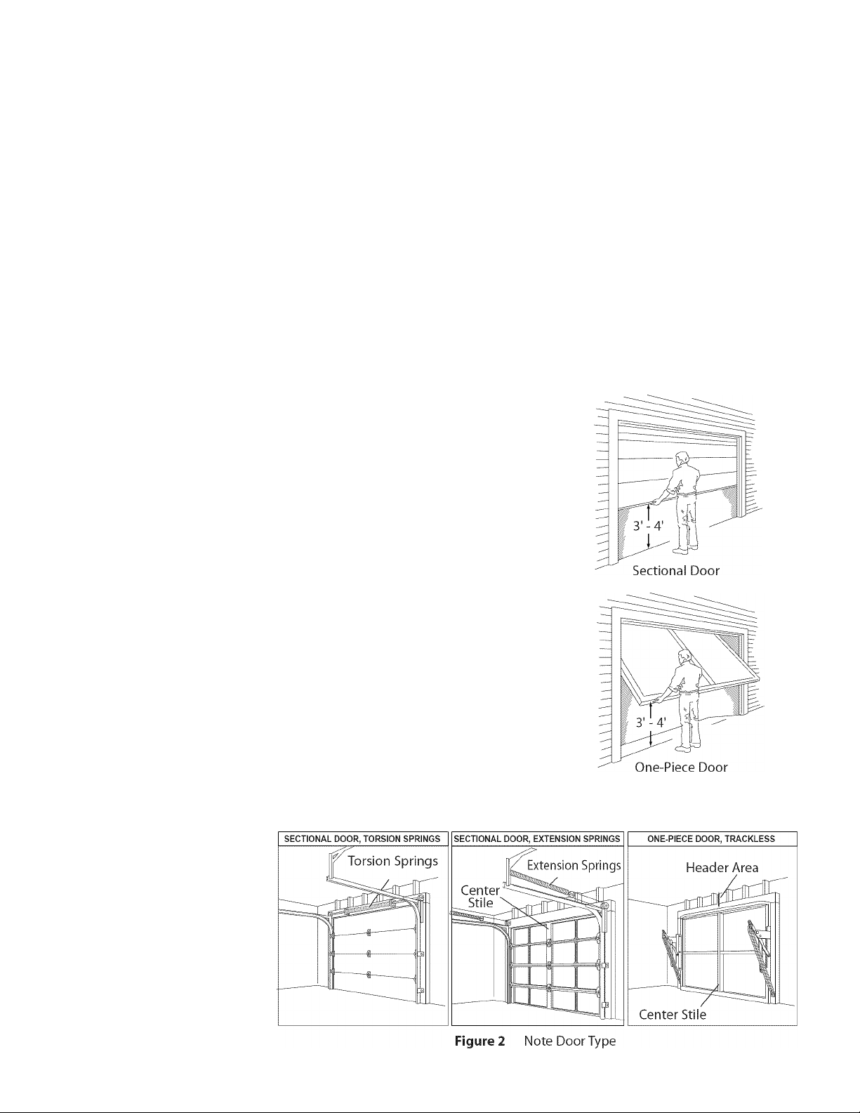
Raise door to 3' - 4' above ground and carefully let go. Door should stay
stationary. Slight movement is acceptable. More than slight movement
means door is out of balance. Contact a Genie Factory Authorized Dealer
or dealer of your garage door
for repairs and adjustments
to door mechanism.
Check door type. Make
a note of whether it is a
sectional or a one-piece
door (Figure 2).
FcM' Help, call 1-800-3S4SEiiE or ¥islt www.gBmet€ompanf.t,om
Figure 1 Checking door balance
Page 4

Measure garage door height (7'-6", 8'-0", or taller) with
tape measure.
A If door height is 7'-6" or less, continue with Check Step 4.
B If your door height is above 7'-6", make sure your rail is long
enough to open the garage door. If there is any question
contact your Customer Service Representative at
1-800-35-GENIE.
NOTE
The header is a heavily reinforced section of the wall just
above the top of the garage door opening.
Find vertical center line of door and header:
• Close door.
• Measure door width at top.
• Mark a point at center of door and on header directly
above door. Draw a center line to connect points.
Find Header Bracket mounting height (Figure 4):
(Do not attach Header Bracket).
• Raise door, watching top edge of door and stop door
when its edge reaches its highest point.
• Measure distance ("H") from top edge of door to floor.
- For sectional doors, add 2-1/2" to"H" Mark a point
on center line. Bottom of Header Bracket will be
installed here.
- For one-piece doors, add 6" to "H" Mark this point on
center line. Bottom of Header Bracket will be
installed here.
SECTIONAL DOOR
ONE-PIECE DOOR
NOTE
For both types of doors:
- If the ceiling in your garage is so low that there is
not at least a 3" space above the Header Bracket
mounting point, contact a Genie Factory
Authorized Dealer.
If a door spring is in the way, place the Header
Bracket avove the spring. Do Not move the door spring.
C Check wall for a stud or a solid header at your mark:
(If checking a finished wall, a stud finder may be helpful).
• If location is above Header, a 2" x 6" board must be
screwed to studs beside your mark with at least two Lag
Screws and Flat Washers (not provided).
• Transfer your mark to new mounting board.
Figure 4 Find Highest Point of Travel
FcM' Help, call 1-S00-3S4SEiiE or visit %wi»i.ferilecornparif.ccirn
Page 5
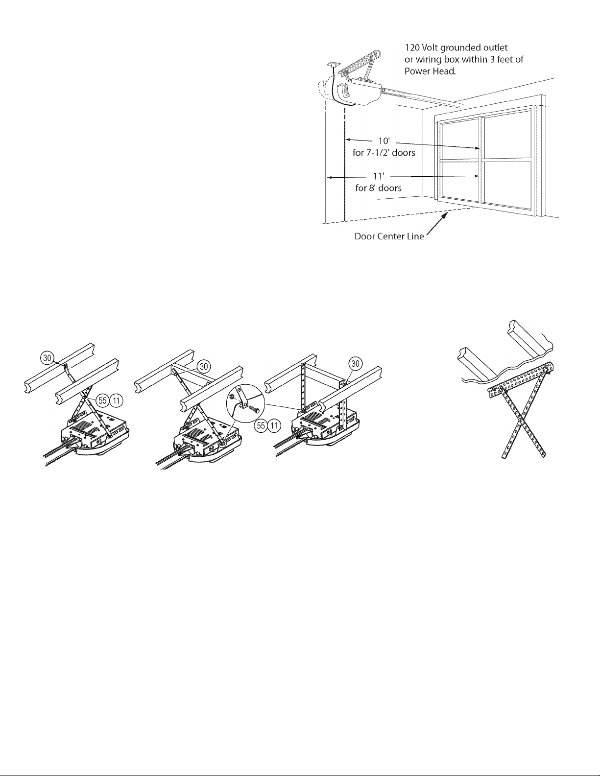
Check ceiling or space above where Opener Power Head will be
mounted (Figure 5):
A Measure from garage door center line mark toward rear
of garage:
• Approximately 10' back if garage has a 7' 6" door.
• Approximately 11' back if garage has an 8' 0" door.
• Approximately 13' back if garage has an 10' 0" door.
• Approximately 14' back if garage has an 12' 0" door.
NOTE
Mounting Straps are included to attach the Opener to most
garage ceilings. Garage construction varies widely.
Additional mounting straps or angle iron may be needed for
your installation.
B Find location of ceiling joist or truss above where Opener
Power Head will be and estimate type and quantity of
materials needed for your installation
(Figure 6).
Figure 5 Check Power Head location
OPEN BEAM CEILING EXAMPLES
Mounting Straps Support board added
for longer spans
Figure 6 Mounting methods for open beam and finished ceilings
Check that there is a 15 Amp 120 Volt grounded electrical
outlet or grounded permanent wiring box (per building code)
within 3' of Opener Power Head:
• If not, an outlet or wiring box must be installed. Contact
a licensed electrician for installation.
• If building codes require permanent wiring, Power Head
must be partially disassembled to install appropriate
wiring in place of Power Cord. See page 19
Perforated
Angle Iron
(Angle iron not included)
FINISHED CEILINGS
Locate ceiling joists or
trusses using
a stud finder
or similar
device.
Attach angle iron
(not included) to
joists or trusses
through finish material
using Lag Screws.
NOTE
Permanent wiring must be installed by a Licensed
Electrician. Not all Genie Factory Authorized Dealers are
Licensed Electricians. Contact someone who is a Licensed
Electrician.
FcM' Help, call 1HI00HJS4SEÌÌE or visit svswi.ferileccirnpiirif.corn
Page 6
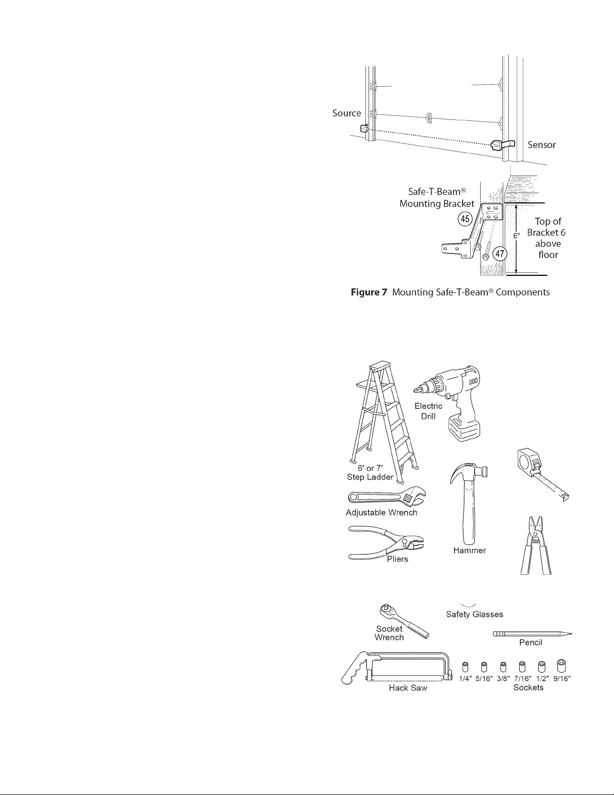
Check for wood garage frame, jamb, or masonry at mounting location
(6" above floor) with attachment tabs facing away from garage door
(Figure 7).
A If you cannot mount Safe-T-Beam® Mounting Bracket to
wood frame:
• Concrete screws and concrete anchors (not included)
must be used to mount Brackets on masonry with
attachment tabs facing away from garage door.
• Safe-T-Beam® Mounting Bracket Extensions may be used
(not included - available from a Genie Factory Authorized
Dealer or through Accessories Order Form on pages 31/32).
A Tools (Figure 8):
B Additional tools to make installation easier:
• Slotted and phillips screw-driver bits
• Stud finder
• Sheet-metal cutting snips
* •
Check that the garage door locks, rope, and T-Handles are removed
from the garage door before starting the installation.
A If your garage does not have a separate entry door, it is highly
recommended to install a Genie Emergency Release Kit (GER-2).
Emergency Release Kit lets you open garage door from outside if
there is a power failure. (Please see Accessories Order Form on
pages 31/32.)
□ Safe-T-Beam® Sensor Mounting Bracket Extensions (dealer)
□ Garage door opener reinforcement bracket (dealer)
□ Garage door frame reinforcement brackets, screws, bracing
or reinforcement kits (dealer)
□ Lag Screws (11/4") for a wood door less than 2" thick (store)
□ Electrical outlet and/or wiring (supplied by a
licensed electrician)
□ Excelerator Extension Kit (for 8' garage doors) (store)
□ Sufficient angle iron or strapping for hanging Power Head
(store)
□ Two 60 Watt light bulbs
(Rough service bulbs recommended)(store)
□ GER-2 Emergency Release Kit for entry during power failure
(store)
□ Wood for header, ceiling, and/or door bracing reinforcement
(if needed)
□ Masonry fasteners for Safe-T-Beam® Bracket installation,
(if needed)
□ Masonry drill bit (if needed)
Phillips Screwdriver
Figure 8 Recommended Tools
1/16" 5/32"
Drill Bit Drill Bit
12' +
Tape Measure^
Wire
Stripper
Carpenter's Level
FcM' Help, call 1-S00-3S4SEiiE or visit %wi»i.ferilecornparif.ccirn
Page 7
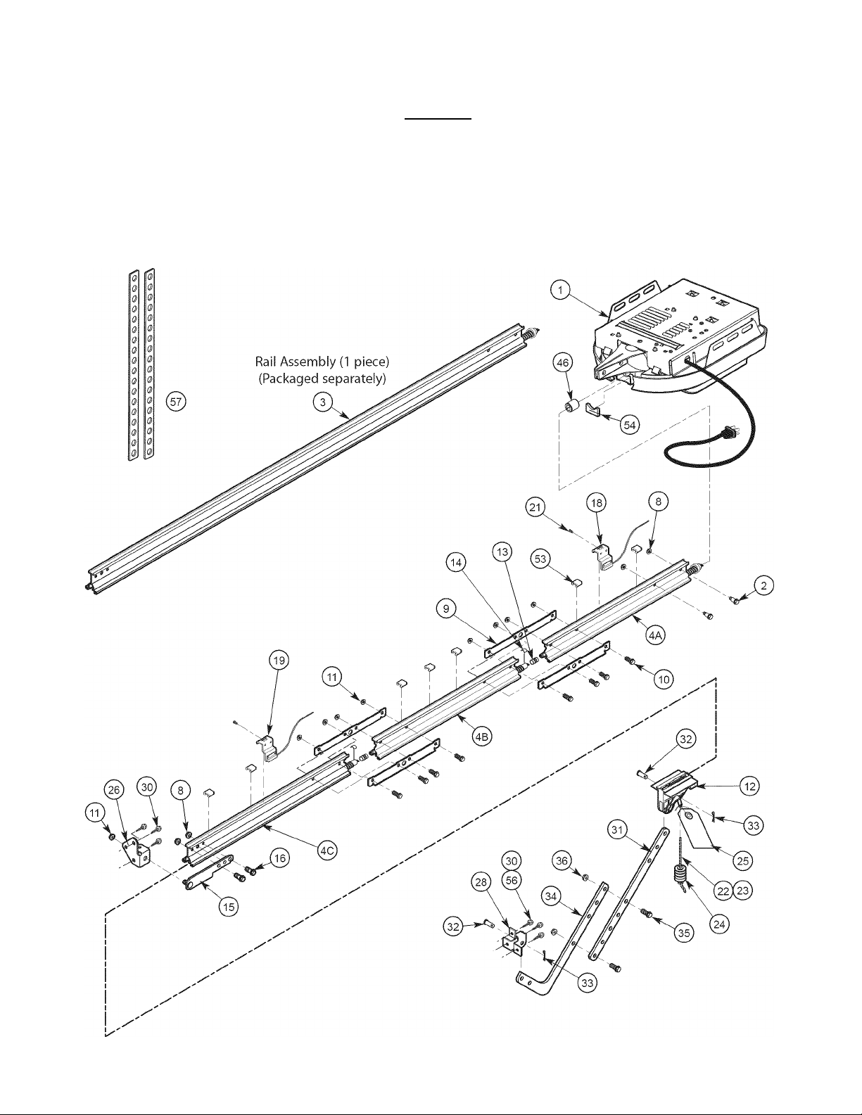
Item Part Name Qua
1 Power Head Assembly (main carton) 1 1
2 1 /4"-20 X13/16" Hex Head Shoulder Bolt (blue bag)
(yellow bolt)
3 Rail Assembly (1 piece)(packaged separately) 1
4 Rail Assembly (3 piece)(main carton) 1
4A First Rail Section 1
4B IVliddle Rail Section 1
4C End Rail Section 1
8 l/4"-20 Hex Serrated Flange Nut (blue bag) 4 4
9 Rail Clamps (blue bag) 4
10 5/16"-l 8 X11 /16" Hex Head Shoulder Bolt (blue bag) 8
11 5/16"-l 8 Hex Serrated Flange Nut (blue & orange bags)
12 (Vlagnetic Carriage Assembly (main carton) 1 1
13 Collar (blue bag) 3
14 Retaining Clip (blue bag) 3
15 Rail Strap (blue bag) 1 1
16 l/4'-20 Hex Head Bolt (blue bag) 2 2
18 Open Limit Switch Assembly (White)(green bag) 1 1
19 Close Limit Switch Assembly (Brown) (green bag) 1 1
21 N0.8-32x1' Hex Head Screw (green bag) 2 2
22 Emergency Release Cord (green bag) 1 1
23 Emergency Release Cord (long)(yellow)
24 Emergency Release Knob (green bag) 1 1
25 Emergency Release Tag (green bag) 1 1
26 Header Bracket (orange bag) 1 1
28 Door Bracket (orange bag) 1 1
30 1/4'x 2' Lag Screw (orange bag)
31 Straight Door Arm (main carton) 1 1
32 Clevis Pin,3/8" X15/16" (yellow bag) 2 2
33 Cotter Pin, .073" dia. (yellow bag) 2 2
34 Curved Door Arm (main carton) 1 1
35 3/8' X 7/8' Hex Head Bolt (yellow bag) 2 2
36 3/8" Hex Serrated Flange Nut (yellow bag) 2 2
37* 2-Conductor Wire (main carton) 1 Roll 1 Roll
38* Insulated Staple (red bag) approx. 30 approx. 30
40* Wall Console (main carton) 1 1
41* #6 X1-1/4" Pan Head Screw (red bag) 2 2
42* Entrapment Warning Label (manual)(main carton) 1 1
43* Safe-T-Beam (STB) Sensor (Green LED)(main carton) 1 1
44* Safe-T-Beam (STB) Source (Red LED)(main carton) 1 1
45* Safe-T-Beam (STB) Bracket (yellow bag) 2 2
46 Coupler (blue bag) 1 1
47* No.10 xl 1/4" Phillips Hex Head Screw (yellow bag) 4 4
48* 1 Button Remote Control (main carton)
49* 3 Button Remote Control (main carton)
50* Wireless Keypad (main carton)
51* 2 Button Remote Control (main carton)
52* Safety & (Vlaintenance Guide (manual)(main carton) 1 1
53 Wire Clip (green bag) 7
54 Bumper (blue bag) 1 1
55* 5/16"-18x 3/4' Hex Head Bolt (orange bag) 3
56 1/4-20 X 3/4" Self-drilling Screw (orange bag) 3 3
57 Mounting Straps (main carton) 2 2
low
utity
lired
Reqi
1-Pc Rail
3-Pc Rail
2 2
“"“/model
12’only
“"“/model
“"“/model “"“/model
“"“/model “"“/model
“"“/model “"“/model
varies/
/model
12
8
“"“/model
Denotes items not shown on page 8. These items will be Illustrated
throughout the manual as required.
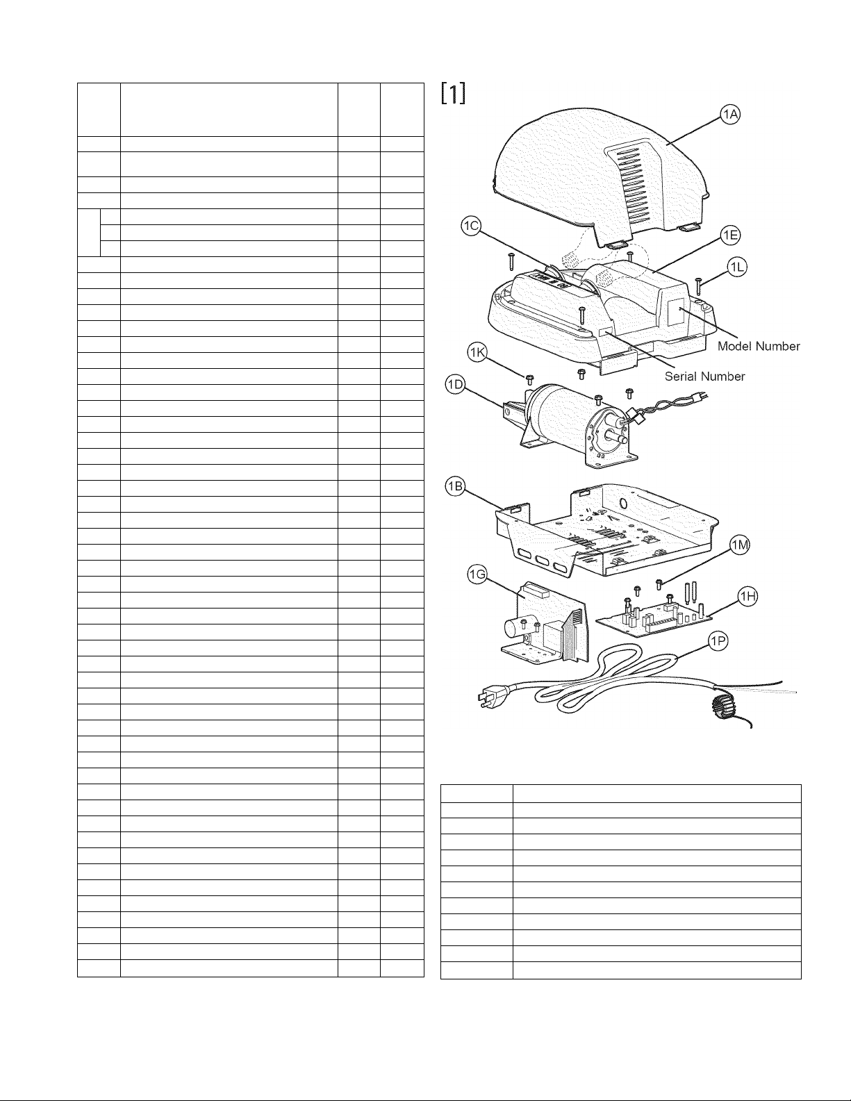
Item Part Name
lA Lens
IB Top Plate Assembly
1C Light Socket (2)
ID Motor Assembly
IE Cover
1G Motor Drive Board
1H Controller Board
IK No. 10-24 X 3/8" Hex Head
1L No.8-32 X 1" Phillips Screw
1M No. 8-32 X 3/8" Slotted Hex Head Screw
IP Power Cord
t-ar Heii: ‘lit or ¥ISIC ' sri lecci rn pa riy. co rri
Page 8
_________________________NOTE
Opener will not function unless Safe-T-Beam® System is installed and Force Controls are properly set.
One-Piece Rail Assembly (Genie Pro only) for 10' or 12' door includes;
• Special "Close" Limit Switch with longer Wires.
• 96" Emergency Release Cord (yellow).
• Rail Support Kit.
________________
FcM' Help, call l-SOOHJSHSEiiE or ¥isit %wi»i.ferilecornparif.ccirn
Page 9
Rail Strap
(15
5/16"-l8 Hex Head Shoulder Bolts
5/16"-l 8 Hex Serrated Flange Nuts
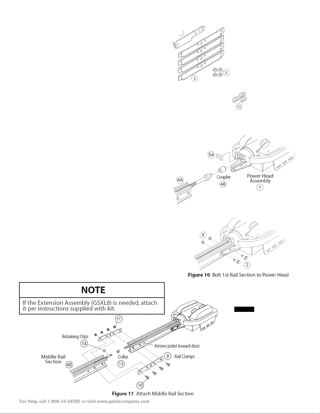
A Turn Power Head upside down and place on a flat
level surface.
B Install Bumper (Figure 9).
C Install Coupler on Motor Shaft (Figure 9).
A CAUTION
The Drive Screw and Rail Liner can slide out of Rail Sections.
Keep Rail Sections level until the Opener is fully assembled.
Connect first Rail Section to Opener Power Head. Connect
with 2 (l/4"-20) (yellow) Hex Head Shoulder Bolts and
2 (1/4" -20) Hex Serrated Flange Nuts (Figure 10).
Finger-tighten until later.
If you have a 1 -piece rail unit, skip Assembly Step 2.
Arrange arrows on Rail Sections to point in same direction
and away from Power Head:
• Push Middle Drive Screw out about 2" toward Power Head.
• Slide Collar over Middle Drive Screw Hook (Figure 11 A).
• Turn Middle Screw by hand to align Drive Screw Hooks
between First and Middle Rail Sections.
• Latch two Hooks together and slide Collar over them
(Figure 11B) and (Figure 11C).
• Snap Clip on Drive Screw next to Collar (Figure 11D).
Attach Middle Rail Section to First Rail Section, using 2 Rail
Clamps, 4 (5/16"-18) Hex Shoulder Bolts, and 4 (5/16"-18) Hex
Head Serrated Flange Nuts onto Bolts (Figure 11).
Finger-tighten until later. (Middle Rail Section looks the
same on both ends. See page 8.)
Attach End Rail Section to Middle Rail Section following
procedures in step A & B.
flt© ¥¥(16:
Rail Clamps Serrated Flange Nuts Shoulder Bolts Head Bolts
%
Coupler
(remove backing)
First Rail
Section
Figure 9 Install Bumper, Coupler and 1st Rail Section
l/4"-20Hex l/4"-20 Hex Head l/4"-20Hex
(yellow)
0
Bumper Collars -r spare Retaining Clips -r spare
Hardware (blue bag)
Bumper
0
f©,
11 A. Slip on collar
11B. Engage Hooks
lie. Slide Collar over Hooks
11D. Snap on Retaining Clip
Ehnm
Page 10
Magnetic Carriage
Assembly ^
Release
Position
A Place Magnetic Carriage Assembly Lever in "release" position.
B Slide Magnetic Carriage Assembly into slot on End Rail
Section with arrow pointing away from the Power Head
(Figure 12).
A Attach Rail Strap to End Rail Section with 2 (l/4"-20) Hex
Head Bolts and 2 (l/4"-20) Serrated Flange Hex Nuts
(Figure 13).
B Tighten snugly but Do Not over-tighten.
A Align all Rail Sections so Magnetic Carriage Assembly can
slide freely along length of Rail.
B Securely tighten all fasteners now. Do Not over-tighten.
Engaged Position
Toward Power Head End Rail Section
^ 0
Figure 12 Slide Magnetic Carriage onto Rail
Rail Strap
® © ®_
0 0
8^
Figure 13 Attach Rail Strap
White
n Limit
S
Ij
Wire
As^^mbly
I 21
#8-32 X 1
Hex Head Screws
Toward door
and header
\ End Rail Section
(ic)
Wire Clips
5^
10
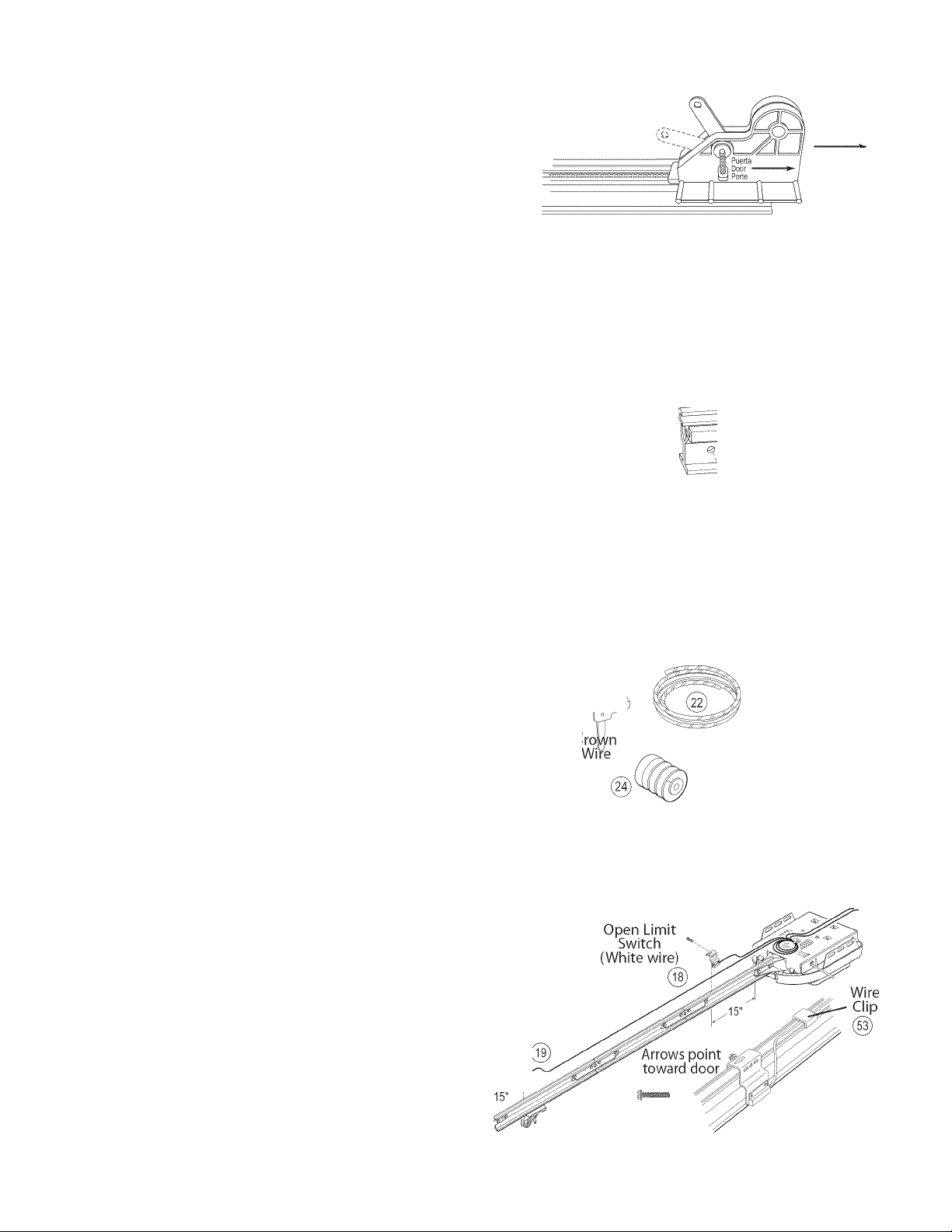
Turn Opener right side up and support Power Head to avoid
damaging the Light Bulb Sockets.
Uncoil Limit Switch Wires and retain Twist Ties.
Place Switches on Rail with arrows pointing away from
Power Head (Figure 14).
Place Close Limit Switch (Brown Wire) 15" from Rail Strap.
Insert (#8-32 X 1") Hex Head Screw into Switch hole and
finger-tighten until later.
Place Open Limit Switch (White Wire) 15" from Power Head.
Insert (#8-32 X 1") Hex Head Screw into Switch hole and
finger-tighten until later.
Emergency
Release Core
25
Close Limit
Switch Assembly
Emergency
Release Knob
Emergency
Release Tag
Hardware (green bag)
Close Limit
Switch
(Brown wire)
#8-32 X 1"
Hex Head^
Screws 0
Figure 14 Install Limit Switches on Assembled Rail
FcM' Help, call 1-S00-3S4SEiiE or visit %wi»i.ferilecornparif.ccirn
Page 11

NOTE
Loosen (Do Not Remowe) Terminal Block Screws.
Limit Switch adjustments and securing the Wires
will be done later.
F Lay Wires in channel on top of Rail and secure with Wire Clips
(Figure 14).
G Coil and bundle excess Limit Switch Wires on top of Power
Head with Twist Ties. Leave just enough Wire to reach
Terminals on back of Power Head (Figure 14).
H Turn Opener upside down, and connect Limit Switch Wires to
Power Head Terminal Block (Figure 15):
• Terminal 4: OPEN Limit Switch Wire (white).
• Terminal 5: OPEN Limit Switch Wire (white) and
CLOSE Limit Switch Wire (brown).
• Terminal 6: CLOSE Limit Switch Wire (brown).
Tie overhand knot at one end of Emergency Release Cord.
Thread opposite end of Cord through Knob and hole in
Magnetic Carriage Assembly Release Lever (Figure 16).
C
Tie overhand knot at this end of Emergency Release Cord.
D
Attach Emergency Release Tag to Magnetic Carriage
Assembly Release Lever.
Figure 15 Connect Limit Switch Wires to Power
Head Terminal Block
Please note the following information so it is available if you need
to call us:
Date purchased: ____
Serial number (Figure 17):
Model number (Figure 17):
Dealer Name:
Dealer Address:
City:
State:
Zip:
Phone:
/ /
NOTE
Please keep original or photocopy of your sales receipt with
this manual for future reference should service ever be
required.
Figure 17 Model and Serial Numbers
FcM' Help, call IHIOOHJSHSEiiE or visit svswi.ferileccirnpiirif.corn
11
Page 12

NOTE
For lightweight garage doors, make sure you have installed
the proper reinforcement (See Check Door Condition and
Thickness on page 3).
A CAUTION
The Header Bracket must be fastened to the garage
framing. Do Not fasten the Header Bracket to drywall,
particle board, plaster, or other such material.
It may be necessary to attach a 2" x 6" board across the
wall studs above the door header to serve as a
mounting plate for the Header Bracket. The Bracket can
then be mounted at the proper location and have
sufficient support.
If a door spring is in the way, place the Header Bracket
above the spring. Do Not move the door spring.
Mount directly
into header
Alternative Header Bracket orientations
Figure 18 Attach Header Bracket above Garage Door
Use of Header Bracket
support board
If needed, attach a 2" x 6" board (Figure 18) (also see page 4)
with at least two (four is recommended) Lag Screws and Flat
Washers (not supplied).
B Attach Header Bracket to header at mark above door.
NOTE
Mounting variations are shown in Figure 18. Any of these
may be used depending on space. However, it is critical that
the point where the Rail attaches to the Header Bracket be
on the center line of the door.
Mark 3 hole positions.
Drill 3 (5/32") pilot holes.
Attach Header Bracket with 3 (1/4" x 2") Lag Screws.
12
FcM' Help, call 1-SOOHJS4SEiiE or ¥isit %wi»i.ferilecornparif.ccirn
Page 13

A CAUTION
Doors made of masonite, lightweight wood, fiberglass, metal,
or other lightweight materials must be properly braced
before mounting door Opener.
(28
(5^ or (g)
(28)
SECTIONAL DOORS ONE-PIECE DOORS
Center Line of dooL,-::;:=:gi J Center Line of door .
For stictional doors;
A Place Door Bracket on door center line, no lower than top
roller, and mark holes (Figure 19).
B Attach Door Bracket:
• For metal doors, use 3 (1/4" -20 x 3/4") Self-Drilling
Screws (provided).
• For wood doors, use 3 (1/4" x 2") Lag Screws or
3 (1/4" X 11 /4") Lag Screws (not provided).
NOTE
Before installing, check length of the included Lag Screws vs.
the thickness of your garage door. For doors thinner than 2",
use 11/4" Lag Screws. Check door condition and thickness.
See page 3.
For ontf-plecef doors:
A Position Door Bracket on door's center line, as high as
possible or on top of door.
B Attach Door Bracket:
• For metal doors, use 3 (1/4" -20 x 3/4") Self-Drilling
Screws.
• For wood doors, use 3 (1/4" x 2") Lag Screws.
/. I OR
Attach no "
lower than.1
top rollers
Optional Door Operator Bracket (not included)
Figure 19 Attach Door Bracket
■'Attach at j
highest point j
on door
A While supporting the Power Head, place threaded end of Rail
Strap Bolt through Header Bracket hole (Figure 20).
B Attach (5/16"-18) Flange Nut to Rail Strap Bolt.
Finger-tighten until later.
FcM' Help, call 1-800-3S4SEiiE or visit svswi.ferileccirnpiirif.corn
13
Page 14

A Raise and support Opener Power Head (along door center
line) higher than highest point of door travel (using step
ladder, etc.) (Figure 21).
B Measure distance from Opener to garage ceiling.
A CAUTION
Mounting Brackets must be fastened to garage framing.
Do Not fasten to drywall, particle board, plaster, or other
such materials.
NOTE
SECTIONAL DOORS
Rail Should be level or dip down slightly.
Make sure the rail of your supported Power Head is
slightly higher than tne highest point of door travel
by raising the door to check. Adjust as needed.
Materials needed for mounting Opener Power Head
to garage may vary. Read all instructions completely.
Garage constructions differ. Extra material may be
needed. See Check Power Head Mounting Area on
page 5.
Install Mounting Straps and/or support brackets (angle iron
not included) to joists or trusses and to mounting slots in
Opener. Use (5/16"-18 x 3/4") Hex Head Bolt, (5/16"-18)
Serrated Flanged Nut, and (1/4" x 2") Lag Screws as needed
(Figure 22).
Securely tighten all fasteners now. Do Not over-tighten.
OPEN BEAM CEILING EXAMPLES
Mounting Straps Support board added
for longer spans
ONE-PIECE DOORS
Set clearance at 1 "-1V2" between Rail and door at
Figure 21 Checking Power Head position
FINISHED CEILINGS
Perforated
Angle Iron
Locate ceiling joists or
trusses using
a stud finder
or similar
device.
14
Attach angle iron
(not included) to
joists or trusses
through finish material
using Lag Screws.
(Angle iron not included)
Figure 22 Mounting methods for open beam and finished ceilings
FcM' Help, call 1-S00-3S4SEiiE or visit %wi»i.ferilecornparif.ccirn
Page 15

For stictiorial cii3ors:
A Attach Curved Door Arm to Door Bracket with Clevis Pin and
Cotter Pin (Figure 23).
B Attach Straight Door Arm to Magnetic Carriage Assembly.
C Attach both Arms together with 2 (3/8" x 7/8") Hex Head
Bolts and 2 (3/8") Serrated Flange Hex Serial Number
Nuts so overall length is as short as pos
sible. Securely tighten fasteners.
D Adjust height of Emergency Release Cord Knob to 6' above
floor:
• Pull Cord through Magnetic Carriage Assembly Lever
until Knob is 6' from floor.
• Tie a new overhand knot in Cord at Magnetic Carriage
Assembly Lever.
For one-piece cli3cirs:
A Attach Straight Arm to Door Bracket with Clevis Pin and
Cotter Pin (Figure 24).
B Attach Curved Arm to Magnetic Carriage Assembly.
C Attach both Arms together with 2 (3/8" x 7/8") Hex Head
Bolts and 2 (3/8") Serrated Flange Hex Nuts so overall length
is as long as possible. Securely tighten fasteners.
D Adjust height of Emergency Release Cord Knob to 6' above
floor:
• Pull Cord through Magnetic Carriage Assembly Lever
until Knob is 6' from floor.
• Tie a new overhand knot in Cord at Magnetic Carriage
Assembly Lever.
Safe-T-Beam® (STB) Brackets
#10-16 X 11/4"
Phillips Hex Head Screw
Hardware (yellow bag)
As short as
possible
32
Clevis Pins Cotter Pins
3/8"X 7/8"
Hex Head Bolts
3/8" Hex Serrated
Flange Nuts
A WARNING
Do Not skip Step D above!
Failure to comply may leave Emergency Release Knob within
reach of children. If the Knob is pulled with garage door fully
or partially open, garage door may close without warning!
FcM' Help, call 1-800CJS4SEÌÌE or visit svswi.ferileccirnpiirif.corn
^(3^ @Door Arm
^ Curved
Figure 24 Assemble Arms (ONE-PIECE)
15
Page 16

^ ELECTRICAL WARNING
Ensure there is No power to the Opener before installing
Safe-T-Beam® System Wires. If Opener is plugged into outlet,
Unplug it now.
Safe-T-Beam® Sensor
(Green LED)
@)
Safe-T-Beam® Source
(Red LED)
NOTE
The Opener will not close the door automatically unless the
Safe-T-Beam® System is installed.
Install Safe-T-Beam® Source and Sensor (Figure 25):
• Mark both sides of garage door frame or wall 6"
above floor.
• Hold Bracket against door frame or wall. Check if Bracket
extends out from wall far enough so tongue of Bracket is
beyond door, tracks, or any door hardware. If not, Safe-T-
Beam® Mounting Bracket Extensions are available from a
Genie Factory Authorized Dealer or through the
Accessories Order Form.
- Blocks of wood, etc. may be substituted
for extensions.
• Position top of Mounting Bracket at 6" mark and fasten
with 2 (#10-16 X 1-1/4") Phillips Hex Head Screws
per Bracket.
NOTE
Mounting Brackets can be attached to brick walls or concrete
floor using masonry anchors (not included).
Slide onto
tongue of
Bracket until^
it clicks into (45)
place
Figure 25 Install Safe-T-Beams®
Top of
Bracket 6"
above
floor
B Attach Safe-T-Beam® Source (Red LED) and Sensor (Green
LED) to Brackets (Figure 25):
• For single-door garages.
- Determine which side of garage receives the most
direct sunlight, and place Source (Red LED) on this
side whenever possible.
• For multiple-door garages see (Figure 26).
- Preventing crossed signals is critical.
- Place Source and Sensor modules on adjacent doors
facing in opposite directions.
NOTE
To help prevent interference from the sun, the Safe-T-Beam®
Sensor (Green LED) may be placed further away from the
door opening, where it will spend more time in the shadows.
Slide the Safe-T-Beam® Source and Sensor onto the
tongues of the Brackets until they click into place.
Check final height of Lens (Figure 27).
16
Top edge of Lens
5" - 6" above floor
Figure 27 Final Check Safe-T-Beams®
FcM' Help, call 1-S00HJS4SEÍÍE or visit %wi»i.ferilecornparif.ccirn
Page 17

^ CAUTION
Staples which are too tight may cut or pinch Wires. Cut or
pinched Wires can cause the Safe-T-Beam® System to stop
working. When installing the Insulated Staples, make sure
you fasten them only as tightly as needed to hold the
Wire securely.
Install Safe-T-Beam® Wiring (Figure 28):
• Route Wire and Insulated Staples
(Figure 29 and Figure 30).
- Securely fasten Wires with Insulated Staples as
you go. Staples should be snug only.
- Wires between garage wall and Power Head should
be run on top of Rail and underneath Wire Clips.
• Attach Wires to Safe-T-Beam® Sensors.
- Split and strip Wire ends to be connected as shown.
- Loosen Terminal Screws.
- Insert each Wire under flat plate and tighten Screw.
It does not matter which Wire, white or striped, goes
on which Terminal.
• Attach Wires at Power Head.
- Wires are connected to Terminals #2 and #3 on
Power Head Terminal Block. It does not matter which
Wire, white or striped, goes on which Terminal.
• Check the following.
- Ensure that no part of door or its hardware is in path
between Source or Sensor Lenses.
• Ensure that tops of Lenses are between 5" - 6" above
floor. Brackets are flexible and can be adjusted slightly
if needed.
NOTE
The Safe-T-Beam® alignment check will be performed
following connection to electrical power.
Do Not plug in yet!
Wire Clips
) B /[
i iji)pjpi|i|ejfl| 11
■) ! i r
\ \l ! STB I 1/ /
' Terminal '
attachments
at Power Head
Figure 29 Wiring Method A
Insulated
Staples
1(38)
Terminal i
- attachments " . . ,
at Safe-T-Beam® Leave slack for
¡ÎÎ s
adjustment
//
0
FcM' Help, call 1-800HJS4SEiiE or visit svswi.ferileccirnpiirif.corn
Wire Clips 0
Terminal '
attachments
at Power Head
Figure 30 Wiring Method A
.
.....
Insulated
Staples
(Ss)
• M S’
Leave slack for
adjustment
17
Page 18

A WARNING
Security
Vacation
Verify there is no power to the Opener before installing Wall
Console Wires.
* •
NOTE
More than one lighted Wall Control per Opener will cause
a malfunction.
Wall Console (Figure 31):
• Has a Security Vacation Lock Switch which disables
all controls.
• LED Indicator shows whether system is powered, locked,
or unlocked. Makes Console easy to find in dark.
• Controls door Opener from inside garage.
• Independent Light Control allows convenient manual
control of Opener Lighting System.
Find a convenient mounting location;
• Within direct sight of garage door.
• At least S' above floor (to prevent small children from
operating garage door).
• Away from any moving garage door or Opener parts (you
should not be able to reach door while standing at
Wall Console).
c
Ensure Vacation Lock Switch is in UNLOCKED position.
D
Wire Wall Console to Opener (Figure 32):
• On Power Head, connect Striped Wire to Terminal #1 and
White Wire to Terminal #2.
• On back of Wall Console, connect Striped Wire to
terminal "B"and White Wire to Terminal "W"
Attach Wall Console onto wall at location found above with 2
(#6 X 11/4") Pan Head Screws.
Remove protective backing from Entrapment Warning Label,
and attach it to wall near Wall Console.
Figure 31 Wall Console
18
A CAUTION
Use of any wall consoles other than the type included
will prevent the light from working properly and could
cause the door to operate on its own.
Cut or pinched Wires can cause the Wall Console to stop
working. When using the Insulated Staples, be sure to
only tap them in as far as needed to hold the
Wire snugly.
FcM' Help, call l-SOOHJSHSEiiE or visit %wi»i.ferilecornparif.ccirn
Page 19

A electrical warning
To reduce the risk of electrical shock, this equipment has
a grounding type Plug that has a third (grounoing) Pin.
This Plug will only fit into a grounding type outlet. If the
Plug does not fit into the outlet, contact a qualified
electrician to install the proper outlet. Do Not change
the Plug in any way.The door Opener must be properly
grounded to prevent personal injury and damage to the
components.
The electrical power to the door Opener Must Be removed
when the Motor Cover is removed. Electrical power must
remain off while making electrical connections.
A Check building codes:
• If building code requires Opener be permanently wired
to building, have a licensed electrician perform step B.
• If you are not installing permanent wiring, go to step C.
B Instructions for licensed electrician - connecting power
with permanent wiring (Figure 33):
• Remove power from circuit.
• Remove Motor Cover.
• Remove and discard Power Cord.
- Cut off Power Cord inside Power Head as near Strain
Relief as possible.
- Remove Knock-Out Plug, Strain Relief, and Power
Cord. (Cut Ground Wire on line side ofToroid).
- Dispose of Plug, Strain Relief, and Power Cord.
• Install required entrance bushing.
• Connect permanent wiring to Power Head Wires.
- White supply line to Opener White Wire.
- Black supply line to Opener Black Wire.
- Ground to Opener Green Wire.
- Replace Motor Cover.
•
NOTE
Use only Underwriters Laboratories, Inc. (U.L.)
recognized wire nuts.
The Circuit Boards are light sensitive. Ensure the
Motor Cover is installed before energizing
the Opener.
Knockout
- Restore Power to circuit.
Connecting Power with Plug:
• Plug Opener into a grounded outlet as stated in previous
electrical warning.
Perform Safe-T-Beam® alignment check:
• Check if Safe-T-Beam® Source Red LED is glowing
continuously (OK) or blinking (problem).
• If Red LED is blinking twice, adjust Sensor Brackets as
needed to make Red LED glow continuously. (Refer to
page 26.)
FcM' Help, call 1-800-3S4SEiiE or ¥islt i«%wi.ferileccirnpiirif.corn
19
Page 20

Setting Close Limit Switch (Figure 34):
• Check that Magnetic Carriage Assembly is disengaged.
• With garage door fully closed, slide Close Limit Switch
until it is aligned with Carriage Assembly Magnet.
• Tighten Set Screw. Do Not over-tighten.
Setting Open Limit Switch:
• Manually open garage door to full open position.
• Slide Open Limit Switch until it is aligned with Carriage
Assembly Magnet.
• Tighten Set Screw. Do not over-tighten.
• Re-engage Magnetic Carriage Assembly.
of
NOTE
Little effort is required to turn the Force
Adjusting Knobs.
If the door stops moving while opening or
closing, adjust the Open Force or Close Force
Controls
increase the force) and retry the step.
The Open Force and Close Force Controls are to
be set to the minimum force necessary to
ensure the door smoothly opens fully and
closes completely.
The garage door will move slowly the first
time it runs, until the Opener "learns" the
type of door.
Ensure the Magnetic Carriage Assembly is
engaged and is between the two Limit
Switches before operating the Opener.
slightly clockwise (to slightly
A WARNING
The garage door opens rapidly, and can cause serious
injury or death.
Keep the path clear.
Position the ladder to the side of the Power Head so it is
clear of all moving parts of the Opener and the door.
Set the door Opener to use the minimum force needed
to open the door.
A Pre-set Force Controls to midpoint between fully counter
clockwise and fully clockwise (Figure 35).
B Adjust the Close Limit Switch:
• Press Wall Console to close garage door.
- If door does not close completely, measure distance
from bottom of door to floor. Move Limit Switch
same amount toward door and try again.
- If door reverses after contacting floor, move Limit
Switch toward Power Head and try again.
- If door reverses before contacting floor, increase
Close force and try again.
- If door fails to move, check Safe-T-Beam® System. See
Safe-T-Beam® Troubleshooting Guide on pg. 26, and
Opener System Self-diagnostic Troubleshooting
on pg.27.
• Tighten Limit Switch Set Screw. Do not over-tighten
(strip) Limit Switch Set Screw.
C Adjust Open Limit Switch:
• Press Wall Console to open garage door.
- If door does not open completely, move Limit Switch
toward Power Head.
- If door opens completely, but motor continues to
run, move Limit Switch toward door.
• Tighten Limit Switch Set Screw. Do not over-tighten
(strip) Limit Switch Set Screw.
Close Limit Switch
(door fully closed)
Carriage
(disengaged)
Open Limit Switch Switch
(door fully open)
Carriage
(disengaged)
Figure 34 Setting Limit Switches
Figure 35 Making Force Adjustments
Switch
Magnet
Magnet
20
FcM' Help, call 1-S00-3S4SEiiE or visit %wi»i.ferilecornparif.ccirn
Page 21

________
NOTE
____________
NOTE
To protect your new investment, your Excelerator® is
equipped with a Timer and Cycle Counter which work
together to prevent any chance of heat damage to
electrical circuits caused by too many cycles in too short
a time. If your Opener suddenly stops responding to the
Wall Console -
Do Not Unplug the Unit - simply wait
10 minutes for theTimer/CycIe Counter to reset itself
and try again.
Unplugging the unit will prevent the Timer/Cycle
Counter from resetting.
Test Door Opener:
Run door up and down a few times using Wall Console
and observe door travel.
Repeat steps above as needed to set Limit
Switch positions.
Adjust Open Force to minimum needed:
Place door in closed position using Wall Console.
Gently adjust Open Force fully counterclockwise
(minimum force).
Run Opener using Wall Console.
Observe that door runs to Open Limit Switch.
- If not, adjust Open Force Control slightly clockwise,
close garage door, and open it again.
Repeat steps above until garage door runs smoothly
from Close Limit Switch to Open Limit Switch.
Adjust Close Force to minimum needed:
Place door in open position using Wall Console.
Gently adjust Close Force fully counterclockwise
(minimum force).
Run Opener using Wall Console.
Observe that door runs to Close Limit Switch.
- If not, adjust Close Force Control slightly clockwise,
open garage door, and close it again.
Repeat steps above until garage door runs smoothly
from Open Limit Switch to Close Limit Switch.
The door must contact the 2" x 4" board before the
Carriage activates the Close Limit Switch. If not,
readjust the Close Limit Switch.
NOTE
Limit Switch and Force Adjustments must be completed
before checking the contact reverse function (Figure 36).
A Open garage door using Wall Console.
B Lay a 2" x 4" board flat in center of doorway.
C Close door using Wall Console.
D Check that door stops and reverses within 2 seconds after it
contacts board:
• If door does not reverse, decrease Close Force until
door reverses.
• If door still does not reverse, move Limit Switch
toward door.
E Check Safe-T-Beam® System operation:
• If beam is blocked, door will not close.
FcM' Help, call IHIOOHJSHSEiiE or ¥islt i«%wi.ferileccirnpiirif.corn
21
Page 22

A To program one Button of a Remote Control (Figure 37):
• Locate Learn Button and Learn Indicator Light near
Terminal Block on Power Head (Figure 38).
• Press and release Learn Button. Red Learn Indicator Light
will blink 2 times per second.
• Press Remote Control Button once within 30 seconds.
Red Learn Indicator Light will stay lit.
• Press Remote Control Button again. Red Learn Indicator
Light will go out, indicating that memory is stored.
B Program each additional Remote using step A above.
To Erase All ieiricites froiri Power H<?aci Memory
A Press and hold Learn Button on Power Head for 10 seconds or
until Learn Indicator Light goes out. Memory is erased:
• Program Remotes again as needed.
To ieplacts ierriote Control iattery
A Push in on Battery Cover Latch at base of Remote Control
(Figure 39):
• Use coin, pen, screwdriver or any similar device.
- Cover snaps open.
• Replace old Battery with new ^EVEREAD% A23,
12 Volt Battery.
B Snap Battery Cover closed.
NOTE
Each Remote Control must be programmed
separately.
The Remote Controls will not cause the door
Opener to close the garage door if the Safe-T-
Beam® System is malfunctioning.
When programming the Remote Controls, they
must be at least 24'Arom the Antenna Wire.
If the red Learn Indicator Light blinks
approximately 4 times per second,
programming has stopped. If programming
has stopped, repeat the above steps.
Each Button on a 2 or 3 Button Remote Control
is for a different Opener. You cannot use more
than one Button per Remote, per Opener.
A maximum of seven Remote Controls or
Wireless Keypads can be stored into the
Receiver at one time. If a Remote Control
becomes lost, or if you want to delete a Remote
Control or Wireless Keypad, see "To Erase All
Receiver Memory."
05
1 Button
Remote
48
2 Button
Remote
3 Button
Remote
A WARNING
A moving garage door may cause serious injury or death.
• Keep people clear of opening while door is moving.
• Do not allow children to play with the Remote Controls.
If the Safety Reverse does not work properly:
• Close the door and disconnect the Opener using the
Emergency Release Cord.
• Do not use the door Opener, Remote Controls, or
Wireless Keypad.
• Refer to the door and door Opener Owner's Manuals
before attempting any repairs.
Press Button on Remote Control. Garage door will move.
Press Button again. Garage door will stop:
• The door automatically stops at the end of the open or
close cycle.
Press Button again. Garage door will reverse.
Figure 37 Genie Remote Controls
Figure 38 Learn Code Button and Indicator Light
.... Visor Clip
Push to open
Battery Cover
Model
Number
iiJO'
I
Figure 39 Remote Control Battery Replacement
22
FcM' Help, call 1-SOOHJS4SEÌÌE or visit www.gBmstompsmi.mm
Page 23

A WARNING
A Moving door can cause serious injury or death.
1 Keep people clear of opening while door is moving.
2 Do Not allow children to play with Wireless Keypad.
3 During programming, the door opener could begin
to run, so stay away from the moving door and its
parts.To keep the door from moving, close the door
and disconnect it from the Opener oy pulling the
Emergency Release.
If Safety Reverse does not work properly
1 Close door and disconnect the Opener using
Emergency Release Cord.
2 Do not use door Opener, Remote Controls, or
Wireless Keypad.
3 Refer to Door and Door Opener Owner's Manuals
before attempting any repairs.
NOTE
FOR CONVENIENCE — Program Keypad BEFORE mounting.
A Set Wireless Keypad PIN (Personal ID Number):
• Activate programming mode.
- Press (in order)
- Red LED blinks - once per second.
• Enter your PIN (3 to 8 characters).
• Press
- Red LED blinks - twice per second and turns off.
B Programming One Door Operator:
• Find the Learn Code Button and Learn Code
Indicator LED on your door opener.
- If your door opener has a black antenna
wire, the Learn Code Button and Indicator
LED are located near the antenna.
(The light lens may need to be opened)
- If your door opener does not have an
antenna,you have an external receiver.
The external receiver cover must be
removed to access the Learn Code
Button and Indicator LED.
• Press the Learn Code Button.
- Learn Code Indicator LED (on Opener)
will blink.
• Enter your PIN and press
- Learn Code Indicator LED stays on.
• Press again.
- Learn Code Indicator LED turns off
C Operating One Door Operator:
• To move the garage door:
- Enter your PIN.
- Press(
__________
If the door does not move, check the red LED on
Keypad. If the LED is blinking rapidly, the PIN was
entered incorrectly. After the LED stops blinking,
re-enter your PIN and try again.
Any keypad button will control the door for
30 seconds after the door starts moving.
Rapid Blinking of the red LED indicates an error.
After a few seconds the LED will turn off. Start over.
NOTE
___________
Proceed to"iloijritirig Ifireless ICef fjac!."
Pri3graii'iirJri§ for 2 or 3 Door Operi<?rs
A Set Wireless Keypad PIN (Personal ID Number):
• Activate programming mode.
- Press (in order) ©©©^P-
- Red LED blinks - once per second.
• Enter your PIN (3 to 8 characters).
• Press
- Red LED blinks - twice per second and turns off
B Programming the Keypad for Multiple Door openers:
All sJcicir openers will use the same PIN.
• Enter your PIN and press
- Red LED blinks - once per second.
• Press again.
- Red LED blinks - twice per second.
• Press the number of doors (total) you wish
to control ( or
• Press 1^^^).
- Red LED blinks several times and turns off
Programming Door Openers:
• Decide which door will be door #1, #2 and #3.
• Press the Learn Code Button (see Figure 1).
- Learn Code Indicator LED (on Opener) blinks.
• Enter your PIN and press .
- Learn Code Indicator LED stays on.
• Press the number you have picked for this
door Opener (© or ^ or @).
- Learn Code Indicator LED stays on.
• Press
- Learn Code Indicator LED turns off.
Repeat step A above for each door opener.
Each door opener must be programmed to receive the
signal from the Wireless Keypad.
FcM' Help, call IHIOOHJS.GEiiE or visit svswi.ferileccirnpiirif.corn
23
Page 24

(Continued)
Operating 2 or 3 Door Openers:
• To move one of the doors.
• Enter your PIN.
• Press ,
Press door opener number (C1J or or
Mount Keypad. (Mounting screws located inside
battery compartment.)
• Remove Battery Cover. See Figure 3.
• Drill a 1/16" pilot hole for the top mounting screw.
• Install a screw into the drilled hole,
leaving a 1/8" gap between the
screw head and the wall.
See Figure 2.
• Hook the Keypad over the screw.
• Mark,drill pilot hole and fasten
bottom screw.
• Reinstall Battery Cover.
A Enter your PIN
• Press
B Enter theTemporary PIN (from 3 to 8 characters).
• Press .
Erase old PIN:
Press and hold in order
- Red LED will blink once and turn off.
• Release all buttons.
Programming Door Opener(s).
• Return to "Programming for 1 Door Opener"or
"Programming for 2 or 3 Door Openers."
DO NOT reprogram the Door Opener(s).
Temporary PIN remains active until the next time your
normal PIN is entered.
24
FcM' Help, call l-SOOHJSHSEiiE or visit www.gBmstompsmi.mm
Page 25

Snap Lens Hinges into
slots on back of Motor Cover
60 Watts
maximum
Figure 41 Install Lens Cover and Light Bulbs
Install two 50 Watt light bulbs (not included) into Light
Sockets (Figure 41):
• Rough service, 130 Volt bulbs are recommended.
Install Lens into slots in Motor Cover.
B
C
Install Genie Emergency Release Kit (GER-2) accessory,
if purchased.
Installation is now complete.
Trarisiriitter Cöinpliarice 5Jtatemerit
Transmitters comply with all United States and Canadian legal requirements
as of the date of manufacture. No warranty is made that they comply with all
legal requirements ofany other jurisdiction. If transmitters are to be used in
another country, the importer must determine compliance with any local
laws and regulations which may differ from United States and Canadian
requirements prior to use.
Los transmisores cumplen con todas las reglamentaciones legales de los
Estados Unidos y del Canadá, en la fecha de fabricación. Ninguna garantía
se da que cumplan con todas as reglamentaciones legales de ninguna otra
jurisdicción. Si los transmisores se van a utilizar en otro país, el importador
debe determinar si cumplen con las reglamentaciones y leyes locales que
puedan ser diferentes a las reglamentaciones de los Estados Unidos y del
Canadá, antes de usar los mismos.
Les émetteurs sont conformes à la réglementation américaine et canadienne
à compter de leur date de fabrication. Aucune garantie n'est stipulée
indiquant qu’ils sont conformes à toutes les prescriptions juridiques d'autres
autorités. Si les émetteurs sont utilisés dans d'autres pays, il incombe à
l'importateur d'en déterminer leur conformité aux lois et règles locales
pouvant différer de celles des États-Unis et du Canada avant toute
utilisation desdits émetteurs.
Sendegeräte entsprechen allen gesetzlichen Bestimmungen in den USA und
Kanada zum Zeitpunkt der Herstellung. Wir übernehmen keine
Gewährleistung für die Einhaltung aller gesetzlichen Bestimmungen in
anderen Ländern. Sollen Sendegeräte in anderen Ländern eingesetzt werden,
so muss der Importeur vor dem Gebrauch sicherstellen, dass die Sendegeräte
auch solchen lokalen Bestimmungen entsprechen, welche von den
Bestimmungen der USA und Kanadas abweichen,
«ihTtœ 01. « T'ÄÄft
I' 7 >X 5 -Vó'-H. u
spsff a* »»íe
Push in
Latches
to
close Lens
A Monthly:
• Door springs and door hardware:
- Oil door roller, bearings, and hinges using silicone
lubricant or light oil.
A WARNING
Do not operate door automatically or manually if springs
are broken. Contact a Genie Factory Authorized Dealer for
service or call Customer Service at 1-800-35-GENIE.
• Balance Door.
- Close door.
- Release Magnetic Carriage Assembly from Rail Assembly
by pulling down on Emergency Release Knob.
- Raise door manually 3'- 4' and verify that door stays at
that position. See Check Step 2 on page 3.
NOTE
When the door is 3' - 4' above the ground, the door
should stay open. Slight movement is acceptable. If
the door moves too much, contact a Genie Factory
Authorized Dealer for service or call Customer Service at
1-800-35-GENIE.
- Reattach Magnetic Carriage Assembly to Rail Assembly:
a. Pull the Emergency Release Knob toward Power Head.
b. Close door.
Contact Reverse Test.
- Perform Installation Step 10 on page 21.
If the door fails to reverse on contact with the board,
adjust the Close Force Control as specified in Set Limit
Switches and Force Controls on page 20. If the Opener
still fails, contact a Genie Factory Authorized Dealer for
service or call Customer Service at
Yearly:
• Wipe off old excess lubricant from Drive Screw.
• Lubricate Drive Screw with Genie Lubricant (GLU-3)
NOTE
Use ONLY Genie Lubricant
may damage the Opener.
GLU-3
Lubricant
1-800-35-GENIE.
GLU-3). Other lubricants
LfnSüft. |lISÍ,a0ttJl(C56ÍI®ffifi§Wíbnb0IMAr¿;#|7S?,f:
¿ s, 5 fc 0. «1 A# H nnáf, átfi A B 0 W A 2ptM A A b ¿ S «
fgbítíttliíAUÍ-a'A,
E0j^D|Ejse DRuf nm aeioiiAi «5 w»» gzisiioj s^aiikhi
ttjEjof SMcf 7|Ej c\E awasi Hë gsjoj s.^ aUJOii tcjEjof Sfe aiêJ
ë siôMEK eia MazsDiEjgoi 7|E| CB xigoiiAf Afsa ëSJSAfe
A®5|7|0|| o>A1 nR3t 7imq.fijo| SëAfîfafe CUXlEaëë n A|«°|
gm 5BII0II n|E|0| IfA|°| 01^1 igsiiot îfMcK
FcM' Help, call 1-800-35-GEiîE or visit LVLWi.ferilsccirnpiirif.corn
FCC AND IC CERTIFIED
All devices comply with Part 15 of the FCC Rules.
Operation is subject to the following two conditions: (1)
this device may not cause harmful interference, and (2)
this device must accept any interference received, includ
ing interference that may cause undesired operation.
25
Page 26

^WARNING
TO REDUCE THE RISK OF SEVERE INJURY OR DEATH
1 READ AND FOLLOW ALL INSTRUCTIONS.
2 Never let children operate or play with the Door Controls. Keep the Remote Control away from children.
3 Always keep the moving door in sight and away from people and objects until the door is completely closed.
NO ONE SHOULD CROSS THE PATH OF THE MOVING DOOR.
4 NEVER GO UNDER A STOPPED, PARTIALLY OPEN DOOR.
5 Test Opener monthly. The door MUST reverse on contact with a 1-1/2" high object (or a 2" x 4" board laid flat)
at the center of the doorway on the floor. After adjusting either the Force or the Limit of travel, retest the Door
Opener. Failure to adjust the Opener properly may cause severe injury or death.
6 When possible use the Emergency Release only when the door is closed. Use caution when using this Release
with the door open. Weak or broken springs are capable of increasing the rate of door closure and increasing
the risk of severe injury or death.
7 KEEP GARAGE DOORS PROPERLY BALANCED. See Owner's Manual. An improperly balanced door increases the
risk of severe injury or death. Have a Genie Factory Authorized Dealer make repairs to cables, spring
assemblies, and other hardware.
8 SAVE THESE INSTRUCTIONS.
^WARNING
Use the Wall Console included with Opener. Any other wall console can cause the Opener to operate unexpectedly and
the light to stop working.
1 So'r i ■ i iED) insor (Green LED) 1 i ■ . .iible Problem Solution 1
26
tl' "
OFF OFF
OFF ON
2 BLINKS, Pause
(Repeat) , ON
2 BLINKS, Pause
(Repeat)
3 BLINKS, Pause
(Repeat)
4 BLINKS, Pause
(Repeat)
OFF
ON
ON
|_ Normal operation ^
1 • Power Head not powered i
• Wiring from Power Head bad
• Wiring to Source missing or bad
• Power has been interrupted
• Beam not aligned
1 • Beam obstructed
• Sensor defective
• Wire to Sensor missing or bad
• Sensor defective
• Sensor receiving interference • Determine source of interference
• Source not sending pulses
• Source defective
FcM' Help, call l-SOOHJSHSEiiE or ¥isit %wi»i.ferilecornparif.ccirn
None required
• Check breakers, fuses, plugs 1
• Check wiring for obvious shorts
• Check wiring
• Remove power and reapply
• Check Source, Sensor alignment
• Check for obstruction i
• Contact Customer Service
• Check wiring
• Contact Customer Service
• Contact Customer Service
• Contact Customer Service
• Contact Customer Service
Page 27

Of
See Status Light on FigureSS, page 22)
u See ablem /Vhat to Do Reference
1 BLINK, 1 Motor Drive
1 Pause Board back in (reapply power), and activate from Wall Console.
(Repeat) Interrupt
Normal
. operation
restored
If the problem
recurs automatic garage door balance detection system. An improperly
Operation not
restored
1
INKS, Controller
Pause Board back in (reapply power), and activate from Wall Console.
(Repeat) 1 Interrupt
3 BLINKS, Opener
Pause Overheated for internal clock to provide additional cycles. Cycles are restored
(Repeat) or at a rate of 5 cycles per 10 minutes of rest.
Over-cycled
4 BLINKS, Force Settings
Pause Incorrect
(Repeat)
5BLINKS, Safe-T-Beam®
Pause Malfunction
6 BLINKS, Wall Console
Pause does not work
(Repeat)
INKS, Limit Switches
Pause not working
(Repeat)
8 BLINKS, Wall Console
Pause , locked Unlock switch.
(Repeat)
J
__________
e
Reset Opener—unplug (or disconnect power), wait 5 seconds, plug
«
First Cycle will run at slow speed.
«
Check door condition. NOTE: This Opener is equipped with an See Door
balanced door, damaged or worn counter-balance spring, binding
Joor hardware or rollers may result in a "ONE-BLINK" signal.
lontact Customer Service for further assistance.
«
Check door condition. l.See page 3.
«
Have a Genie Factory Authorized Dealer check: 2. See door
- Fuse on Motor Drive Board.
- Ribbon Cable on Motor Drive Board is properly inserted into
Connector on Controller Board.
«
Contact Customer service for further service.
«
Reset Opener — unplug (or disconnect power), wait 5 seconds, plug
«
Have a Genie Factory Authorized Dealer check that Ribbon Cable on
Motor Board is properly inserted into connector on Controller Board.
e
Contact Customer Service for further assistance.
«
Do not unplug or disconnect power from Opener. Wait 10 minutes
«
Contact Customer Service for further assistance.
«
Check Force Settings. NOTE: Force Settings are not pre-set at factory. l.See page 20.
«
Check door condition. 2. See Door
«
Contact Customer service for further assistance. Safety Guide
«
Check Safe-T-Beam® Self-diagnostic System. NOTE: Safe-T-Beam® See page 16.
System must be installed and operational to enable door to close.
e
Contact Customer Service for further assistance.
«
Check Wall Console Wiring for shorts, tight Staples, or pinched Wires. See page 18.
«
Check Wiring Connections at Power Head and Wall Console.
e
Contact Customer Service for further assistance.
«
Check Limit Switch Wire connections to Terminals on Power Heac See page 20.
«
Check for shorted or pinched Wires under Limit Switch Brackets.
«
Contact Customer Service for further assistance.
«
Vacation Locking Switch on Wall Control is in "Lock" mode. See page 18
Contact Customer Service for further assistance.
•
1
1
Safety Guide
Safety Guide
: i
1 1
The status LED Indicator Light is located under the Lens Cover.The Green LED light will turn ON, then OFF when
power is applied to the Opener. If LED stays ON, have a Genie Factory Authorized Dealer check the Controller
Board, or call Customer Service at 1-800-35-GENIE.
If Safe-T-Beam® problems exists, the door can be closed electrically by holding the Wall Console Button down
until door is fully closed.
The Remote Controls and Wireless Keypad will not work without a working Safe-T-Beam® System.
FcM' Help, call IHIOOHJSHSEiiE or ¥islt i«%wi.ferileccirnpiirif.corn
27
Page 28

Problem
Opener does not run
from Remote Control
Door Opener starts
for no apparent reason
Door starts down, then
stops before it is
completely closed
Door starts down, then
stops and goes back up
Door will only run closed
Door will only run open
Lights will not turn off
Door starts up, but stops
before it is
completely open
Operator runs, but door
does not move
Wall Console Vacation
Lock function does
not work
What To Do
1. Check power source.
A. If Opener is connected to an outlet:
• Plug a working lamp into outlet used for Power Head.
• If lamp glows, power source and outlet are OK.
• If not, check fuse or circuit breaker or non-compatible GFCI.
NOTE: A licensed electrician must replace non-compatible GFCI's.
B. If Opener is connected to a wiring box:
• Check fuse is not blown, or circuit breaker is "Closed" (not tripped).
• If still no power, have a licensed electrician check circuit and wiring.
2. If power is OK:
• Check connections at Power Head Terminals (see Wall Console Installation page 18), tightening any
loose connections.
Have a Genie Factory Authorized Dealer check that Ribbon Cable between Controller Board and Motor Drive
Board is properly connected to Connectors on Circuit Boards,or call Customer Service at 1-800-35-GENIE.
Check Wires to ensure that they are not cut (Stapes can cut insulation and short Wires).
Replace any shorting Staples and shorted Wires.
Was Remote Control lost or stolen? If so, erase all Remote Control codes from Receiver's memory
and reprogram for remaining remote controls. (See Erase All Receiver Memory on page 22).
Ensure that no Buttons are stuck"pushed-in"on Wall Console or any Remote Controls.
Check Close Limit Switch setting (see Set Limit Switches and Force Controls on page 20).
I
I
Adjust as needed.
Check for shorted Wires.
Check garage door for binding.
If a new installation, check Door Arm position.
Check operation of Contact Reverse function.
Check Safe-T-Beam® System for beam obstruction or misalignment of Lenses.
Check Safe-T-Beam® System diagnostic code.
Check Close Force adjustment (see Set Limit Switches and Force Controls on page 20). Adjust as needed.
Check garage door for binding.
Check Open Limit Switch for a short circuit and for proper wiring.
Check Open Force adjustment (see Set Limit Switches and Force Controls on page 20). Adjust as needed.
Check condition of garage door and doorspring(s).
: If you suspect a problem with the garage door hardware or springs, contact a Genie
Factory Authorized De aler for service, or contact Customer Service at 1-800-35-GENIE.
Check Safe-T-Beam® System as detailed in the Safe-T-Beam® System Self-diagnosticTroubleshooting Chart
(see Safe-T-Beam® System Self-diagnosticTroubleshooting Section on page 26).
Check Close Limit Switch for a short circuit and for proper wiring.
Check Close Force adjustment (see Set Limit Switches and Force Controls on page 20). Adjust as needed.
Disconnect Wires connecting Wall Console to Power Head (see Wall Console Installation on page 18).
Check their condition and either replace or reconnect.
Until a replacement Wall Console can be obtained,disconnectWall Console and use only Remote Controls
or Wireless Keypad to operate Opener.
Check (ensure) that garage door and Opener are in good repair, properly lubricated, and properly
balanced as detailed in Maintenance Section.
liCî: If you suspect a problem with the garage door hardware or springs, contact a Genie
Factory Authorized De aler for service, or contact Customer Service at 1-800-35-GENIE.
Check Open Limit Switch for a short circuit and for proper wiring.
Check Open Force adjustment (see Set Limit Switches and Force Controls on page 20). Adjust as needed.
Ensure Magnetic Carriage Assembly is engaged to Rail Drive Screw (see Install Magnetic Carriage Assembly
onto Rails on page 10).
Check Force adjustment (see Set Limit Switches and Force Controls on page 20). Adjust as needed.
Check that all sections of Rail Drive Screw are turning when Motor runs. If not:
- Check condition (not cracked, split, or broken) and placement of Coupler. Replace as needed.
- Check condition (not cracked, split, or broken) and placement of Collar and Clip. Replace them
as needed.
Ensure Magnetic Carriage Assembly is in contact with Close Limit Switch.
Check when door is fully closed, that Carriage activates Close Limit Switch. If not,adjust position of Close
Limit Switch (See page 19).
28
FcM' Help, call 1-SOO-3S-GEiiE or ¥isit %wi»i.ferilecornparif.ccirn
Page 29

C5eri<iral Troubleshooting (Al'imafs Chtick th<i Steitus LED UghtMCoritIriuecll
Li'Oblc.iV; What To Do
Remote Control has less
than 25'operating range
Opener works from Wall
Control, but not from
Remote Control
Noisy operation
Safe-T-Beam® System
Door closes, and Opener
: «
: «
: «
«
Relocate Remote Control inside car.
«
Ensure Remote Control is pointing toward garage door when pressing Control Button.
«
Replace Remote Control Battery ^EVEREJWY, type"A23." (See page 22).
«
Reposition Opener Antenna Wire.
«
Do Not attempt to retune Remote Controls or Receiver.
: «
Program code for each Remote Control into Receiver memory (See Programming the Remote
Control on page 22.
Replace Remote Control Battery ^jtEVERERDY, type"A23." (See page 22).
Check Safe-T-Beam® System for beam obstruction or misalignment of Lenses.
Check Safe-T-Beam® System for any diagnostic codes. If present, troubleshoot as detailed in
Safe-T-Beam® System Self-Diagnostic Troubleshooting Chart (See page 26).
i «
Ensure all fasteners are tightened.
Check that the garage door and Opener are in good repair, properly lubricated,and properly j
balanced. (See Maintenance page 25). i
•
e
Factory Authorized Dealer for service, or contact Customer Service at 1-800-35-GENIE.
% «
If an operational problem exists, Opener will not run closed.
«
Check Safe-T-Beam® System for beam obstruction or misalignment of Lenses.
£ «
Check Safe-T-Beam® System for any diagnostic codes. If present, troubleshoot as detailed in Safe-T-Beam®
System Self-DiagnosticTroubleshooting Chart (See page 26).
£ «
Check position ofWall Console Vacation Lock Switch. It must be in UNLOCKED position for Opener to
1 shuts down open door.
: If you suspect a problem with garage door hardware or springs, contact a Genie
FcM' Help, call IHIOOHJSHSEiiE or ¥islt i«%wi.ferileccirnpiirif.corn
SECONDARY GROUND
29
Page 30

To get warranty service for your Genie product, you must
provide proof of date, and place of purchase of the product.
What is Cmemd
Any defect in material and workmanship from personal, normal
household use in accordance with the Owner’s Manual.
For How Long:;
H8000D Series — Lifetime* on motor, on parts and service.
ISD990 Series — Lifetime* on motor, 5 years* on parts.
ISD990-2 Series — Lifetime* on motor and all parts.
ISD99S Series — Lifetime* on motor and all parts.
ISD99S-2WKM Series — Lifetime* on motor and all parts.
ISDIOOO Series — Lifetime* on motor,aII parts and service.
CMD9900 Series — Lifetime* on motor, 5 years* on parts.
PR099 Series — Lifetime* on motor and all parts.
* for as long as you own your home.This warranty is non-transferable.
This warranty applies only to the consumer who originally purchased
the product.
G <iog ra ph ic Scope:
This warranty applies only to Genie products purchased in the United
States and Canada.
If your Genie product is defective, we will send replacement parts or, at
our option, a replacement unit at no charge to you, excluding shipping,
handling and labor costs. If we send replacement parts for your Genie
product, we may use new or reconditioned parts. If we choose to send
a replacement unit, we may use a new or reconditioned one of the
same or similar design.
LliTiitations;
IMPLIED WARRANTIES, INCLUDING THOSE OF FITNESS FOR A
PARTICULAR PURPOSE AND MERCHANTABILITY (AN UNWRITTEN
WARRANTYTHATTHE PRODUCT IS FIT FOR ORDINARY USE) ARE
LIMITED TO ONE YEAR FROM DATE OF PURCHASE. GENIEWILL NOT PAY
FOR: LOSS OF USE OF YOUR GENIE PRODUCT OR PROPERTY DAMAGE
CAUSED BY YOUR GENIE PRODUCTOR ITS FAILURETO WORK; ANY
SPECIAL INCIDENTAL OR CONSEQUENTIAL DAMAGES; ANY DAMAGES
RESULTING FROM MISUSE OR MODIFICATION OF YOUR GENIE PRODUCT.
Some states and provinces do not allow limitations on how long an
implied warranty lasts or the exclusion of incidental or consequential
damages, so the above exclusions and limitations may not apply.
This warranty is the oniy one we will give on your Genie product, and
it sets forth all our responsibilities regarding your Genie product.
There are no other expressed warranties.
State and Province Rights: This warranty gives you specific legal rights,
and you may also have other rights that vary from state to state and
province to province.
1. Do-It-Yourself Serwice:
Call Genie Customer Service toll free at 1-800-354-3643, or visit
our website at
representatives will assist in diagnosing the problem and will
arrange to supply you with the required parts for do-it-yourself
repairs.Trained service representatives are available Monday Friday, 8:00 AM -11:00 PM,and on Saturday, 11:00 AM - 8:00 PM
Eastern Time (subject to holidays).
You can obtain the name of a Genie Factory Authorized Dealer
by calling the Genie Dealer Locator Service at 1-800-654-3643.
If an Authorized dealer provides warranty service, Genie will not
reimburse you or otherwise be responsible for any labor
charges. Your choice of one of the above described service
options is your remedy under this warranty.
Batteries (which are considered replacement parts)
Installation
Commercial use
Defects resulting from accidents
Damage while in transit to our service location or damage
from alterations
Misuse or Abuse
Lack of proper maintenance
Unauthorized repairs or modifications of the product
Affixing of any attachment not provided with the product
Programming of Remote Control Devices
Programming of Keypads
Safe-T-Beam® adjustment/cleaning
Staples through wiring
Pinched or broken wires
Carriage disengaged
Force Control adjustments
Door out of balance
Broken springs or cables
Power outages
Use of extension cords
Missing or damaged parts on discounted, clearanced, final
sale or taped cartons
Phantom operations
Fire
Flood
Acts of God
Failure to follow the Owner's Manual
www.geniecompany.com.Trained Genie
30
For Help, call l-SOO-35-GEiiE or ¥isit %wi»i.ferilscornparif.ccirn
Page 31

ài
(GIT-1) Deluxe Remote Control with Intellicode®- Allows remote operation of garage door
Controlador remoto de lujo con Intellicode®- Proporcionar operación remoto de la puerta del garaje
Télécommande de luxe avec Intellicode®- Permettre opération éloign"de porte de garage
(GIT-2) 2-Button Remote Control with Intellicode®- Allows remote operation of 2 garage doors
Controlador remoto de 2 funciones con Intellicode®- Proporcionar operación remoto de dos las puertas del garaje
Télécommande à 2 fonctions avec Intellicode®- Permettre opération éloign' deux portes de garage
(GIT-3) 3-Button Remote Control with Inteliicode®- Allows remote operation of 3 garage doors
Controlador remoto de 3 funciones con Intellicode®- Proporciónar operación remoto de tres las puertas del garaje
Télécommande à 3 fonctions avec Intellicode®- Permettre opération éloign' trois portes de garage
(GPWC-2WLB) Lighted Wall Console - Operates Garage Door. Independent light control. Security vacation lock
Consola de pared de 3 funciones - Acciona la puerta del garaje. Control de luz independiente. Cerradura de seguridad para vacaciones
Console murale à trois fonctions - Actionne la porte de garage. Commande d’éclairage Indépendante. Interrupteur de verrouillage de sécurité
(Gil-3) 3-Button Mini Remote Control with Intellicode® - Fits easily into pocket or purse
Minicontrolador remoto de 3 funciones con Intellicode® - Cave fácilmente en el bolsillo o cartera
Mini télécommande à 3 fonctions avec Intellicode® - se glisse dans la poche de veston ou le sac à main
(GWKP) Wireless Keypad Entry System - Operates Intellicode® Garage Door Openers without Remote Control or key
Sistema de entrada por teclado numérico inalámbrico - Acciona los abridores de puertas de garaje Intellicode® sin control remoto o llave
O
Système d'ouvre-porte de garage à clavier sans fil - Actionne les ouvre-porte de garage avec Intellicode® sans télécommande ni clé
a.
(GLU-3) 1/4 oz. Tubes Screw Drive Lubricant (3) - Ensures proper equipment wear protection
1/4 once Lubricante de torniilo accionar (3) - Asegura componente correcto protección por deterioro
La onza 1/4 Lubricant de la vis (3) - Garantir componant exact par système défense vers user
3
(GWB) Universal Wall Button - Provides additional convenient inside operation of door
q:
Botón de pared universal - Proporciona operación conveniente de la puerta desde el Interior
LU
X
Bouton mural universel - Actionne I’ouvre-porte de l’intérieur du garage
ü
(GPS-6) Perfect Stop® - Ensures perfect parking
Stop Perfecto® - Asegura el estacionamiento perfecto
K>
Butoir Perfect Stop® - Permet de stationner à la perfection dans le garage
O
(GSXL-8) Excelerator Screw Drive Extension Kit - An eighteen inch Extension to increase the travel of a Screw Drive Opener to accommodate an eight foot door
El extension desiizante de Excelerator Screw Drive - Una extensión de 18 pulgadas para aumentar la carrera de un abridor deslizable de tornillo, para acomodar una puerta de 8 pies (2,43 m.j
Nécessaire de rallonge du Excelerator Screw Drive - Rallonge de 30 dm (18 po) prolongeant la course de l’ouvre-porte Screw Drive pour une porte de 2,4 m (8 pi) de hauteur
Q
<
(GIRU-1T) Universal Conversion Kit - Converts any Garage Door Opener to a secure radio signal system. Kit includes a Remote Control, Receiver and Transformer
Juego de conversion universal - Convierte cualquier abridor de puerta de garaje a un sistema de señal de radio seguro. El juego incluye un control remoto de abridor de puerta de garaje,
receptor y transformador
Nécessaire de conversion universel - Transforme tout ouvre-porte de garage en système de sécurité à signal radio. Comprend une télécommande d'ouvre-porte de garage, un récepteur et
un transformateur
a:
<
O
60 WATT Enhanced/Rough Service Light Buib - Ensures proper equipment compatability
Bombilla de 60 Vatios - Asegura componente correcto de sistema
Éclairage de 60 WATT - Garantir componant exact par systéme
ù:
<
(GER-2) Emergency Release Kit - Provides access to garage from outside in the event of an electrical power failure
Juego de pica-porte de pestillo - Permitir entrtada desde por fuera de garaje porque corte de eléctrico
Nécessaires de Déclenchement de secours - Le nécessaire de déclenchement de secours est conçupour vous permettre d’accéder à votre garage depuis l’extérieur en cas de panne de
courant et lorsqu’il
O
Q
STB Adapter Brackets (2) - Used in conjunction with standard STB Mounting Brackets. They provide additional clearance along with mounting options
O
El adaptador pone entre paréntesis (2) - Usado en unión con paréntesis uniformes de montar de STB, ellos proporcionan el espacio libre adicional junto con mortar las opciones
Crochets d'adaptateur - Utilisé conjointement avec STB standard monter les crochets, ils fournissent le dégagement supplémentaire avec monter d’options
<
<
No C.O.D. shipments. Please include check or money
order, made payable to The Genie Company. Do not
send cash. Allow 3-4 weeks for delivery. We accept
Visa or Mastercard on phone orders only.
1-800-354-3643. Please have part number and credit
card ready.
Please add local sales tax If you reside In one of
the states listed.
California
Connecticut
Florida
Georgia
Illinois
TOTAL ORDER
SHIPPiNG & HANDLiNG $ 6.00
STATE SALES TAX
GRAND TOTAL
Indiana
Maryiand
Massachusetts
New Jersey
New York
Ohio
Tennessee
Virginia
Wisconsin
Michigan
$
$
$
No se aceptan pedidos de pago contra entrega (COD).
Sírvase incluir su cheque o giro postal, la cuenta
pagadera hecha a The Genle Company. No envíe
dinero en efectivo. Concédanos 3 a 4 semanas para la
entrega. Aceptamos pedidos telefónicos de Visa o
Mastercard. 1-800-354-3643. Sírvase tener listos los
números del modelo y de la tarjeta de crédito.
Sírvase agregar el impuesto de ventas local si usted
reside en uno de los siguientes estados:
Caiifornia
Connecticut
Florida
Georgia
Iliinois
TOTAL DEL PEDiDO
FLETE Y MANEJO $ 5,(10
IMPUESTO DE VENTAS ESTATAL
GRAN TOTAL
Indiana
Maryland
Massachusetts
New Jersey
New York
Ohio
Tennessee
Virginia
Wisconsin
Michigan
$
$
$
Pas d'expédition contre remboursement. Veuillez inclure un
chèque ou un mandat bancaire, le payable fait à The Genie
Company. N’envoyez pas d’argent comptant. Accordez de 3 à
4 semaines pour la livraison. Nous acceptons les commandes
par téléphone avec paiement par carte de crédit Visa ou
Mastercard. 1-800-354-3643. Ayez sous la main le numéro de la
pièce et celui de la carte de crédit.
Veuillez Indiquer les taxes de vente locales si vous résidez
dans l’un des états répertoriés ci-dessous.
Californie
Connecticut
Fioride
Geòrgie
Illinois
COMMANDE TOTALE
MANUTENTION ET EXPÉDITION $ 5.00
TAXE DE VENTE
TOTAL GLOBAL
Indiana
Maryland
Massachusetts
New Jersey
New York
Ohio
Tennessee
Virginie
Wisconsin
Michigan
$
$
$
Prices on Reverse Los Precios en otro lado
For Help, cali 1-800-35-GEiiE or visit yvywi.ferileccirnpíirif.corn
Les Prix sur l’autre côté
31
Page 32

I&
MODEL
MODELO
MODÈLE
GIT-1
GIT-2
GIT-3
GPWC-2WLB
GMI-3
GWKP
GLU-3
GWB
GPS-5
GSXL-8
GIRU-1T
LIGHT BULB
GER-2
ADAPTER
BRACKET
DESCRIPTION
DESCRIPCIÓN
DESCRIPTION
PRODUCT CODE
CÓDIGO
CODE DU PRODUIT
Deluxe Remote Control with Intelllcode®
Controlador remoto de lujo con Intelllcode®
33069R $34.95
Télécommande de luxe avec Intelllcode®
2-Button Remote Control with Intelllcode®
Controlador remoto de 2 funciones con Intelllcode®
33069S $44.95
Télécommande à 2 fonctions avec Intelllcode®
3-Button Remote Control with Intelllcode*
Controlador remoto de 3 funciones con Intelllcode*
33069T $49.95
Télécommande à 3 fonctions avec Intelllcode*
Lighted Wall Console
Consola de pared encender
34292R $13.95
Console murale avec éclairage
3-Button Mini Remote Control with Intelllcode®
Mlnicontrolador remoto de 3 funciones
con Intelllcode®
34909R $39.95
Mini télécommande à 3 fonctions avec Intelllcode®
Wireless Keypad Entry System
Sistema de entrada por teclado numérico inalámbrico
35282R $49.95
Système d’ouvre-porte de garage à clavier sans fil
1/4 oz.Tube Screw Drive Lubricant (x 3)
1/4 once Lubricante de tornillo accionar (x 3)
34965R $1.95
La onza 1/4 Lubrifiant de la vis (x 3)
Universal Wall Button (unlit)
Botón de pared universal (unlit)
34960R $4.95
Bouton mural universel (unlit)
Perfect Stop*
Stop Perfecto®
34964R $4.95
Butoir Perfect Stop®
Screw Drive Extension Kit (For Excelerator)
El extensión de cadena deslizable (Para Excelerator)
Nécessaire de prolongement
33523S $34.95
du coulisseau (Pour Excelerator)
Universal Conversion Kit
Juego de conversión universal
33154R $49.95
Nécessaire de conversion universel
60 Watt Enhanced/Rough Service Light Bulb
Bombilla de 60 Vatios
2621 OA.S $2.95
Éclairage de 60 Watt
Emergency Release Kit
Juego de pica-porte de pestillo
34963R $29.95
Nécessaires de déclenchement de secours
STB Adapter Brackets (2)
El adaptador pone entre paréntesis (2)
34439R.S $4.95
Crochets d’adaptateur (2)
PRICE (US$)*
PRECIO*
PRIX ($ US)*
QTY.
CANTIDAD
OTÉ
TOTAL
TOTAL
TOTAL
OÍ
cl!
lu!
z:!
Ç2|
_j!
3i
QC!
LU!
X!
ii
QC!
<1
(f>\
O!
Q!
Si
QC|
<!
OC!
Í!
O!
Q!
o|
<!
QC!
<
32
Prices subject to change without notice
Valoran el cambio con sujeción a sin nota
Les prix assujettissent pour changer sans la notification
NAME/NOMBRE/
ADDRESS / DIRECCIÓN / ADRESSE
CITY/CIUDAD/VILLE STATE / ESTADO / ÉTAT ZIP / CÓDIGO POSTAL / CODE POSTAL
FcM' Help, call 1-SOOHJS4SEiiE or visit %wi»i.ferilecornparif.ccirri
The Genie Company
22790 Lake Park Blvd.
Alliance, Ohio 44601-3498
 Loading...