

Page 1
EDVR-H Series
DIGITAL VIDEO RECORDER
User Guide
EDVRH-4 4 Channels
EDVR-8 8 Channels
EDVR-16 16 Channels
Page 2
1 DIGITAL VIDEO RECO R DER
SAFETY PRECAUTIONS
CAUTION:
TO REDUCE THE RISK OF ELECTRIC SHOCK, DO NOT REMOVE COVER (OR BACK).
NO USER SERVICEABLE PARTS INSIDE. REFER SERVICING TO QUALIFIED
SERVICE PERSONNEL.
The lightning flash with arrowhead symbol, within an equilateral
triangle, is intended to alert the user to the presence of un insulated
“dangerous voltage” within the product’s enclosure that may be of
sufficient magnitude to constitute a risk of electric shock to persons.
The exclamation point within an equilateral triangle is intended to alert
the user to the presence of important operating and maintenance
(servicing) instructions in the literature accompanying the appliance.
WARNING:
TO PREVENT FIRE OR ELECTRIC SHOCK HAZARD,
DO NOT EXPOSE THIS APPLIANCE TO RAIN OR MOISTURE.
Page 3

2 DIGITAL VIDEO RECO R DER
Contents
Disclaimer ............................................................................................... 4
Warning ................................................................................................... 4
Caution .................................................................................................... 6
Preventing Malfunction .......................................................................... 6
Package Contents .................................................................................. 7
I.CONTROLS ........................................................................................... 8
1. Front Panel ...................................................................................................... 8
2. Rear Panel Connectors ................................................................................. 11
3. Remote Controller ........................................................................................ 12
4. Virtual Keypad for Mouse Control. ............................................................. 13
II. INSTALLATION & CONNECTIONS .................................................. 14
1. Camera, Monitor, Microphone, Alarm sensor and Power cord ................ 14
2. PC system requirement for Network connection. ...................................... 15
III.QUICK SETUP ................................................................................... 16
1. TIME .............................................................................................................. 17
2. RECORD ....................................................................................................... 17
3. ADVANCED ................................................................................................... 18
IV.LIVE VIEWING ................................................................................... 19
1. Display Overview ........................................................................................ 19
2. Multi screen Display and Sequencing ........................................................ 20
2.1 Full Screen Display ....................................................................................................... 20
2.2 Multi screen Display and Sequencing Display. .......................................................... 20
2.3 Repositioning ................................................................................................................. 21
3. Zooming ........................................................................................................ 22
4. Spot Monitor .................................................................................................. 22
5. HDMI output .................................................................................................. 23
V. OPERATION ...................................................................................... 24
1. Main Menu Overview .................................................................................... 24
2. Display Option .............................................................................................. 25
2.1. Display Setup .................................................................................................................. 25
2.2. Sequential Setup (Auto Sequence) ............................................................................... 26
3. Camera Setup ............................................................................................... 27
4. Continuous Recording (Normal Recording) ............................................... 30
5. Schedule Recording ..................................................................................... 32
Page 4

3 DIGITAL VIDEO RECO R DER
6. Event .............................................................................................................. 34
7. Device ............................................................................................................ 35
7.1 GENERAL .......................................................................................................................... 35
7.2 ALARM .............................................................................................................................. 36
8. Network Setup .............................................................................................. 37
8.1. IP setup ............................................................................................................................ 37
8.2. E-Mail ................................................................................................................................ 38
8.3 DDNS ................................................................................................................................. 39
8.4. Router & Port Forwarding .............................................................................................. 40
8.5. MISC. ................................................................................................................................ 42
9. System Setup ................................................................................................ 43
9.1. General ............................................................................................................................. 43
9.2. Time .................................................................................................................................. 44
9.3. Account ............................................................................................................................ 45
9.4. DISK .................................................................................................................................. 46
9.5. UPDATE. ........................................................................................................................... 47
9.6. INFO .................................................................................................................................. 48
VI.PAN/TILT ZOOM CONTROL ............................................................. 49
1. P.T. Z . Menu .................................................................................................. 49
2. Preset & Tour ................................................................................................ 50
3. Custom Functions ........................................................................................ 50
VII.SEARCH/ PLAYBACK ..................................................................... 53
1. Time Search .................................................................................................. 53
2. Log List Search/Alarm, Motion Search ....................................................... 54
VIII.BACKUP .......................................................................................... 55
1. USB Memory Stick Backup .......................................................................... 55
2. External USB HDD Backup .......................................................................... 56
3. CD/DVD –RW Backup ................................................................................... 58
4.How to Play Backup data in USB Memory Stick Backup ........................... 59
5. Back up Range Setup ................................................................................... 60
Appendix 1: WEB SERVER .............................................................................. 61
X.SPECIFICATIONATION ...................................................................... 63
Page 5

4 DIGITAL VIDEO RECO R DER
Disclaimer
z The information in this manual is believed to be accurate and reliable as of the date of
publication. The information contained herein is subject to change without notice. Revisions or
New editions to this publication may be issued to incorporate such change
z We makes no warranties for damages resulting from corrupted or lost data due to a mistaken
operation or malfunction of the Digital Video Recorder, the software, the hard drives, personal
computers, peripheral devices, or unapproved/unsupported devices.
Warning
z Do not cover the ventilation opening or slots on the outer casing. To prevent the appliance
from overheating, provide at least two inches of air space around the vent and the slots.
z Do not drop metallic parts through slots. This could permanently damage the Digital Video
Recorder. Immediately turn the DVR’s power off or unplug the power cord from the power
outlet. Contact a qualified service personnel authorized by your equipment distributor
z Do not attempt to disassemble or alter any part of the equipment that is not expressly
described in this guide. Disassembly or alteration may result in high voltage electrical shock.
Qualified service personnel authorized by your equipment distributor should conduct internal
inspections, alterations and repairs.
z Stop operating the equipment immediately if it emits smoke or noxious fumes. Failure to do
so may result in fire or electrical shock. Immediately turn the DVR’s power off, remove the
power cable from the power outlet. Confirm that smoke and fume emissions have ceased.
Please consult your DVR distributor.
z Stop operating the equipment if a heavy object is dropped or the casing is damaged. Do not
strike or shake. Failure to do so may result in fire or electrical shock. Immediately turn the
DVR’s power off or unplug the power cord from the power outlet. Please consult your DVR
distributor.
z Do not allow the equipment come into contact with, or become immersed in, water or other
liquids. Do not allow liquids to enter the interior. The DVR has not been waterproofed. If
the exterior comes into contact with liquids or salt air, wipe it dry with a soft, absorbent cloth.
In the event that the water or other foreign substances enter the interior, immediately turn the
DVR’s Power off or unplug the power cord from the power outlet. Continued use of the
equipment may result in fire or electrical shock. Please consult your DVR distributor.
Page 6

5 DIGITAL VIDEO RECO R DER
z Do not use substances containing alcohol, benzene, thinners or other flammable substances
to clean or maintain the equipment. The use of these substances may lead to fire. Use a
dry cloth on a regular periodic basis and wipe away the dust and dirt that collects on the
device. In dusty, humid or greasy environments, the dust that collects around the ventilation
or the slots on the outer casing over long periods of time may become saturated with humidity
and short-circuit, leading to fire.
z Do not cut, damage, alter or place heavy items on the power cord. Any of these actions may
cause an electrical short circuit, which may lead to fire or electrical shock.
z Do not handle the device or power cord if your hands are wet. Handling it with wet hands
may lead to electrical shock. When unplugging the cord, ensure that you hold the solid
portion of the plug. Pulling on the flexible portion of the cord may damage or expose the wire
and insulation, creating the potential for fires or electrical shocks.
z Use only the recommended power accessories. Use of power sources not expressly
recommended for this equipment may lead to overheating, distortion of the equipment, fire,
electrical shock or other hazards.
z Do not place the batteries near a heat source or expose them to direct flame or heat. Neither
should you immerse them in water. Such exposure may damage the batteries and lead to
the leakage of corrosive liquids, fire, electrical shock, explosion or serious injury.
z Do not attempt to disassemble, alter or apply heat to the batteries. There is serious risk of
injury due to an explosion. Immediately flush with water any area of the body, including the
eyes and mouth, or clothing that comes into contact with the inner contents of the battery. If
the eyes or mouth contact these substances, immediately flush with water and seek medical
assistance from a medical professional.
z Avoid dropping or subjecting the batteries to severe impacts that could damage the casings.
It could lead to leakage and injury.
z Do not short-circuit the battery terminals with metallic objects, such as key holders. It could
lead to overheating, burns and other injuries.
z The supplied power supply and power cord are designed for exclusive use with the Digital
Video Recorder. Do not use it with other products or batteries. There is a risk of fire and
other hazards.
Page 7

6 DIGITAL VIDEO RECO R DER
Caution
z Do not operate the appliance beyond its specified temperature, humidity or power source
ratings. Do not use the appliance in an extreme environment where there is high
temperature or high humidity. Use the device at temperatures within +0°C - +40°C (32°F -
104°F) and humidity below 90 %. The normal operating power source for this device is DC
12V 50/60Hz.
Preventing Malfunction
z Avoid Strong Magnetic Fields. Never place the DVR in close Proximity to electric motors or
other equipment generating strong electromagnetic fields. Exposures to strong magnetic fields
may cause malfunctions or corrupt image data.
z Avoid Condensation Related Problems. Moving the equipment rapidly between hot and cold
temperatures may cause condensation (water droplets) to form on its external and internal
surfaces. You can avoid this by placing the equipment in an airtight, resalable plastic bag and
letting it adjust to temperature changes slowly before removing it from the bag.
z If Condensation forms inside the Digital Video Recorder. Stop using the equipment
immediately if you detect condensation. Continued use may damage the equipment. Remove
the power cord from the power outlet and wait until the moisture evaporates completely before
resuming use.
CAUTION
- Risk of Explosion if Battery is replaced by an Incorrect Type. Dispose of Used Batteries
According to the Instructions.
- The socket-outlet shall be installed near the equipment and shall be easily
accessible
Page 8

7 DIGITAL VIDEO RECO R DER
Package Contents
Please check the package and contents for visible damage. If any components are damaged or
missing, do not attempt to use the unit, contact the supplier immediately. If the unit must be
returned, it must be shipped in the original packing box.
CONTENTS QUANTITY REMARK
DIGITAL VIDEO RECORDER 1 UNIT
CLIENT SOFTWARE CD 1
REMOTE CONTROLLER 1
BATTERY (AAA size) 1
AC Adapter 1
POWER CORD 1
USER GUIDE 1
Page 9
8 DIGITAL VIDEO RECO R DER
I.CONTROLS
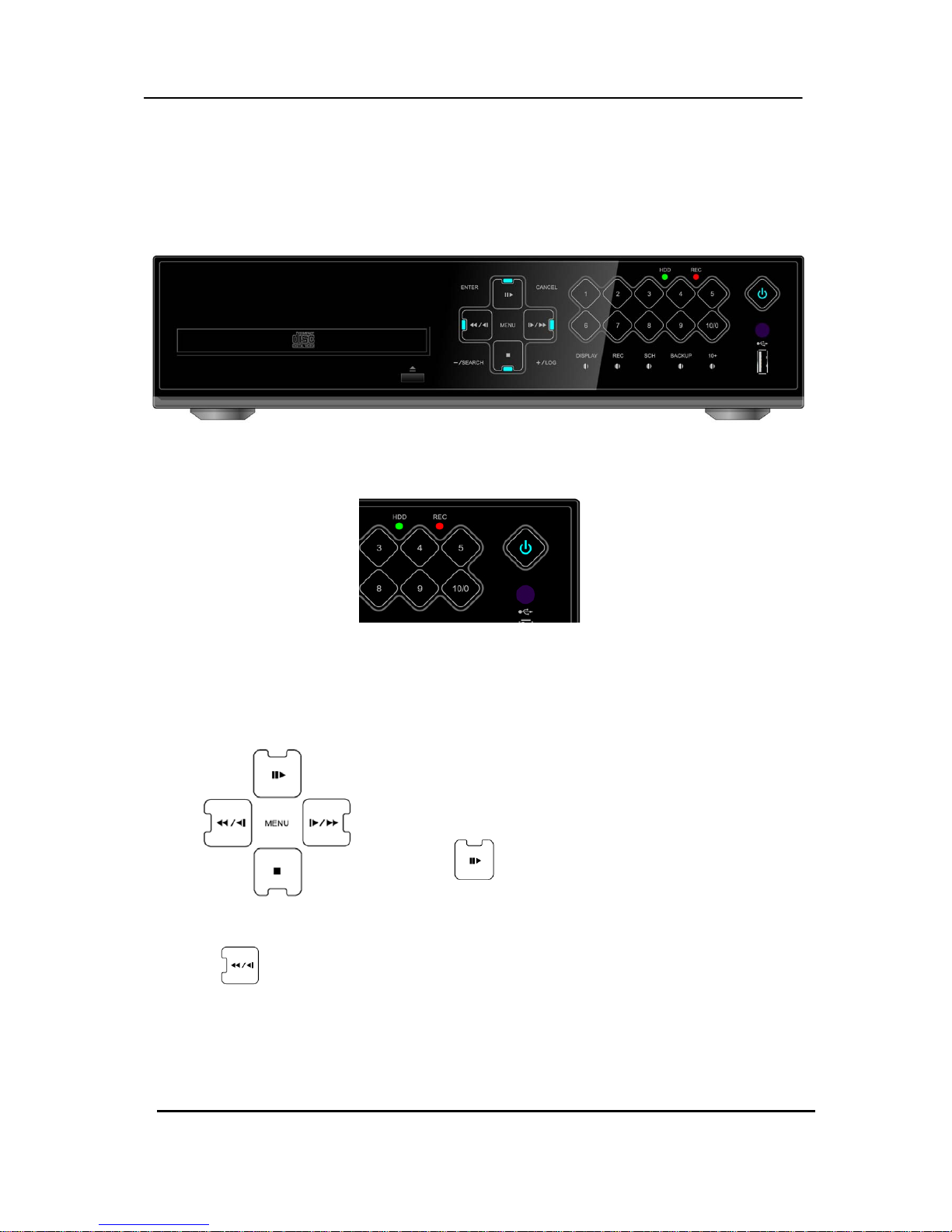
1. Front Panel
1. Mode indicator : 3 LEDs display the status of the Digital Video Recorder.
Power (Blue), Recording (Red) and HDD (Green)
2. Playback / Record control: These functions are used in Live Mode or
Playback mode.
1) Direction buttons: In Menu setup mode, used to
move the cursor.
2)
[Still or Playback]
: This button is used to still or 1 x playback
during playback mode.
3)
[R step or FR ]
① Reverse Step : This button is used to move reverse field by field during STILL mode
② Fast Rewind : This button is used to fast rewind during PLAYBACK mode.
Page 10

9 DIGITAL VIDEO RECO R DER
4) [Stop] :
: This button stops playback
5)
[ F step or FF]
① Forward step : This button is used to move forward field by field (picture by picture)
during STILL mode
② F.F. : This button is used to Fast Forwarding during PLAYBACK mode
3. Menu Button
1)
[MENU]
: Press this button to display the MAIN MENU screen.
2)
[ENTER] :
: Press this button to save menu settings
3)
[CANCEL] :
: Press this button to exit menu without saving.
4)
[ - / SEARCH]
① [ - ] : Press this button to decrease settings
② Search : This button accesses the time search menu. Use the directional
buttons to select the date and the time. Press [Enter] button to start the
playback of the selection.
5)
[ + / LOG]
① [ + ] : Press this button to increase settings
② LOG : Press this button to display the LOG-list screen.
4. Channel / Numeric Buttons
These buttons have a number of functions to enter data and to make selections.
They are used to enter numerical data when prompted for the password, to make
Channel/camera selection, to choose the day in schedule option.
Page 11
10 DIGITAL VIDE O REC ORDER
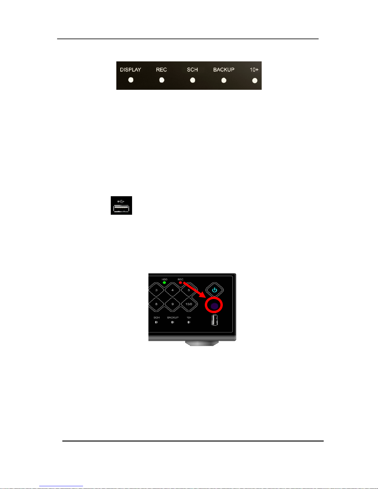
5. Funtion button
1) DISPLAY : Press this button to display the cameras in multi-screen view.
2) REC : Press this button to start recording.
Press the button again or stop button to stop.
3) SCH [Schedule] : Press this button to make scheduled recording standby.
Press the button again to stop.
4) BACKUP : Press this button to go backup menu. You can set the time and channels
to backup footage from the DVR.
5) 10+ : Press this button to choose channels over 10. For example, Press this key and
“6” to see channel “16”.
6. USB Port:
: Connecting USB compatible devices or USB mouse
7. Remote control signal receiver :
Do not block the receiver port on the unit. Doing so may cause the remote controller to
function improperly.
Page 12
11 DIGITAL VIDEO RECORDER
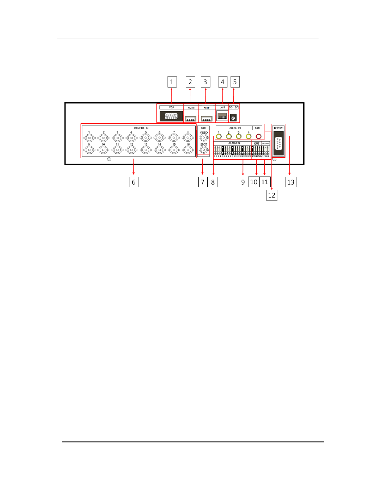
2. Rear Panel Connectors
1) VGA : VGA out connector
2) HDMI : HDMI out connector
3) USB : For connecting USB compatible devices
4) LAN (RJ-45 Ethernet Port) : For connecting to remote PC via Ethernet network.
5) POWER : DC power Jack
6) CAM1~4, 1~8 or 1~16 : BNC input (Camera 1~4, 1~8 or 1~16) connectors
7) SPOT : Spot out connector
8) MONITOR (Composite Output) : BNC standard composite video output connector.
9) SENSOR (ALARM IN 1~4 ,1~8 or 1~16) : For connecting alarm inputs.
10) RELAY (ALARM OUT 1~2) : For connecting alarm out relays.
11) RS-422/485 : For connecting to PTZ camera.
12) AUDIO Input / AUDIO Output connectors : RCA
13) RS-232C : Development purposes only.
Page 13

12 DIGITAL VIDE O REC ORDER
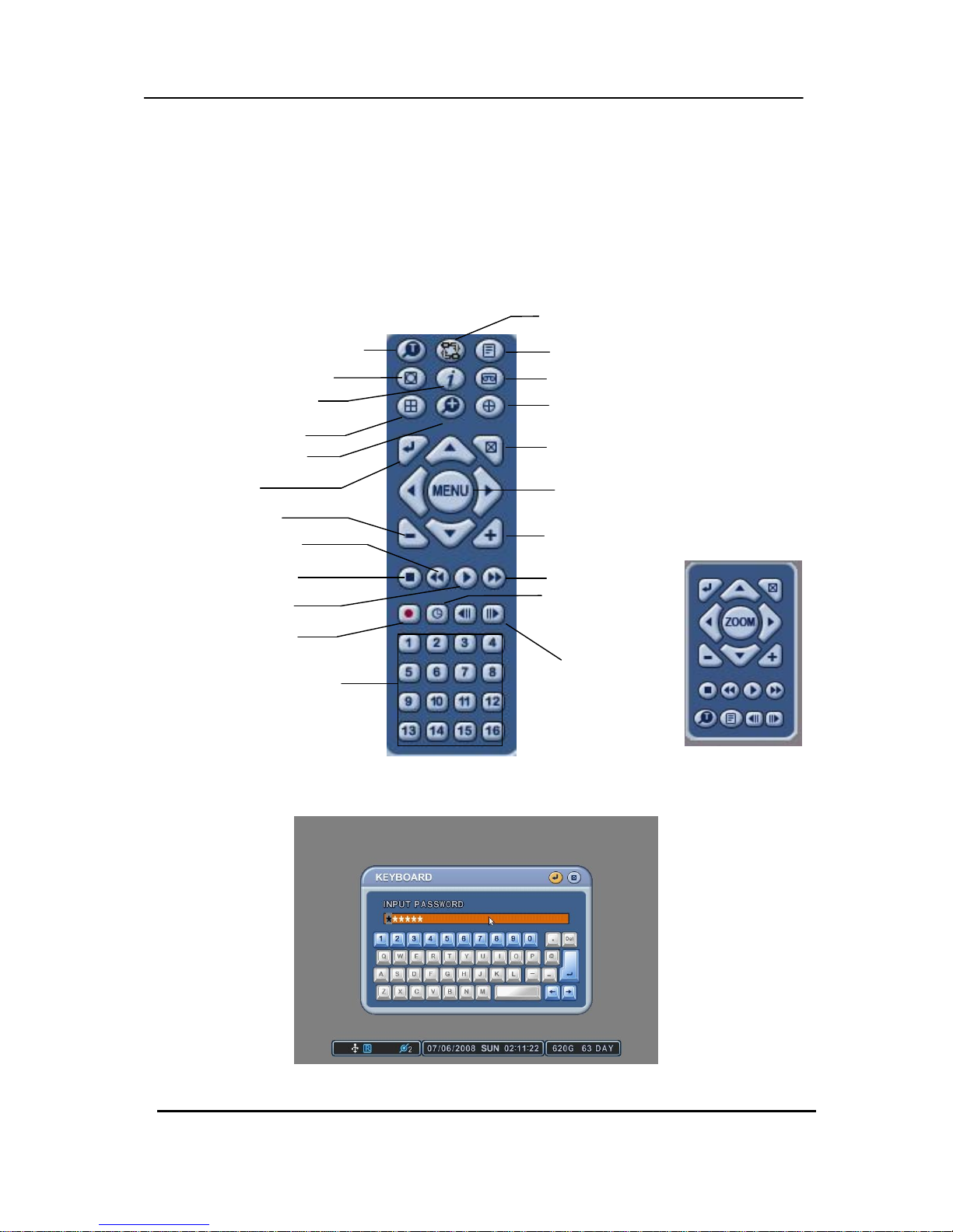
3. Remote Controller
Page 14
13 DIGITAL VIDE O REC ORDER
4. Virtual Keypad for Mouse Control.
This DVR can be controlled by Mouse. Connect a mouse via USB port before use. If you
click right button of your mouse in Live mode and Playback mode, you will see following
virtual Remote controllers respectively and Virtual Keypad will be shown to enter
PASSWORD and Camera Name etc
[LIVE] [PLAYBACK]
[Virtual Keypad]
REWIND
LOG
SPOT OUT
INFORMATION
BACK UP
DISPLAY MODE
PAN/TILT/ZOOM
ENTER
ZOOM
CANCEL / OSD OFF
MENU
+ BUTTON
STOP
PLAY
FAST FORWARD
RECORD
SCHEDUL
/LOGIN
STEP
NUMBERS & ALPHABE T
Repositioning
- BUTTON
TIME SEARCH
Page 15
14 DIGITAL VIDE O REC ORDER
II. INSTALLATION & CONNECTIONS
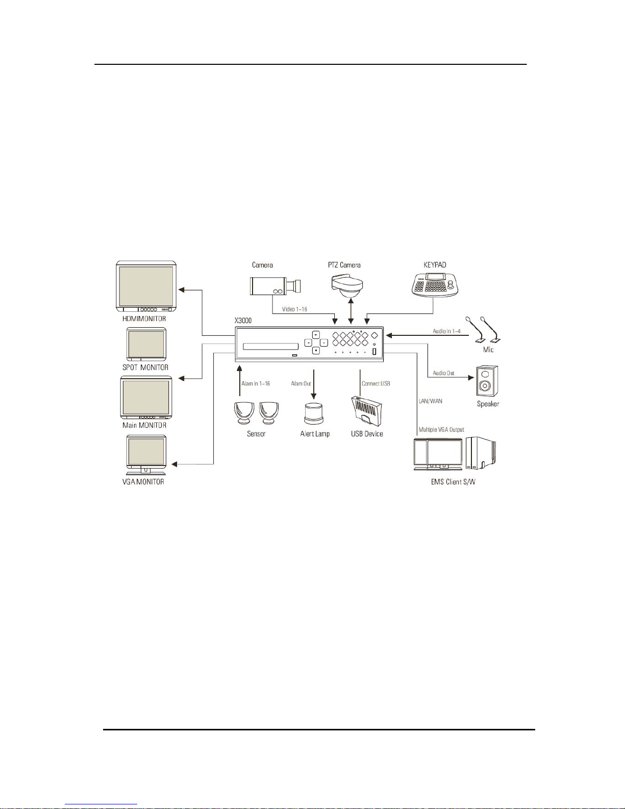
1. Camera, Monitor, Microphone, Alarm sensor and Power cord
1-1. System Configuration Diagram
The following illustration is showing the fully installed system.
Page 16

15 DIGITAL VIDE O REC ORDER
2. PC system requirement for Network connection.
(a) Pentium-4 2.0GHz or higher
(b) 256MB System Memory
(c) 1,024 x 768 Display Resolution, 32 Bit color
(d) Windows XP, VISTA
(e) Spare 10/100-BaseT Ethernet Port
(f) Microsoft DirectX 9.0c
It is recommended to have DirectX 9.0c version in Client PC. DirectX 9.0c is available for
download from Microsoft homepage
(www.microsoft.com/windows/directx).
<Disclaimer>
The remote viewing on network connection may not work on all personal computers due
to difference
in personal settings and hardware configurations.
Page 17
16 DIGITAL VIDE O REC ORDER
III.QUICK SETUP
To turn on the DVR, press [POWER] button on the front panel or on the remote controller.
When the Digital Video Recorder is powered on, the Live Viewing screen will appear in about
30sec.
1) Stop recording first to set QUICK SETUP menu. While DVR is recording, TIME and
RECORD menu is not activated. .
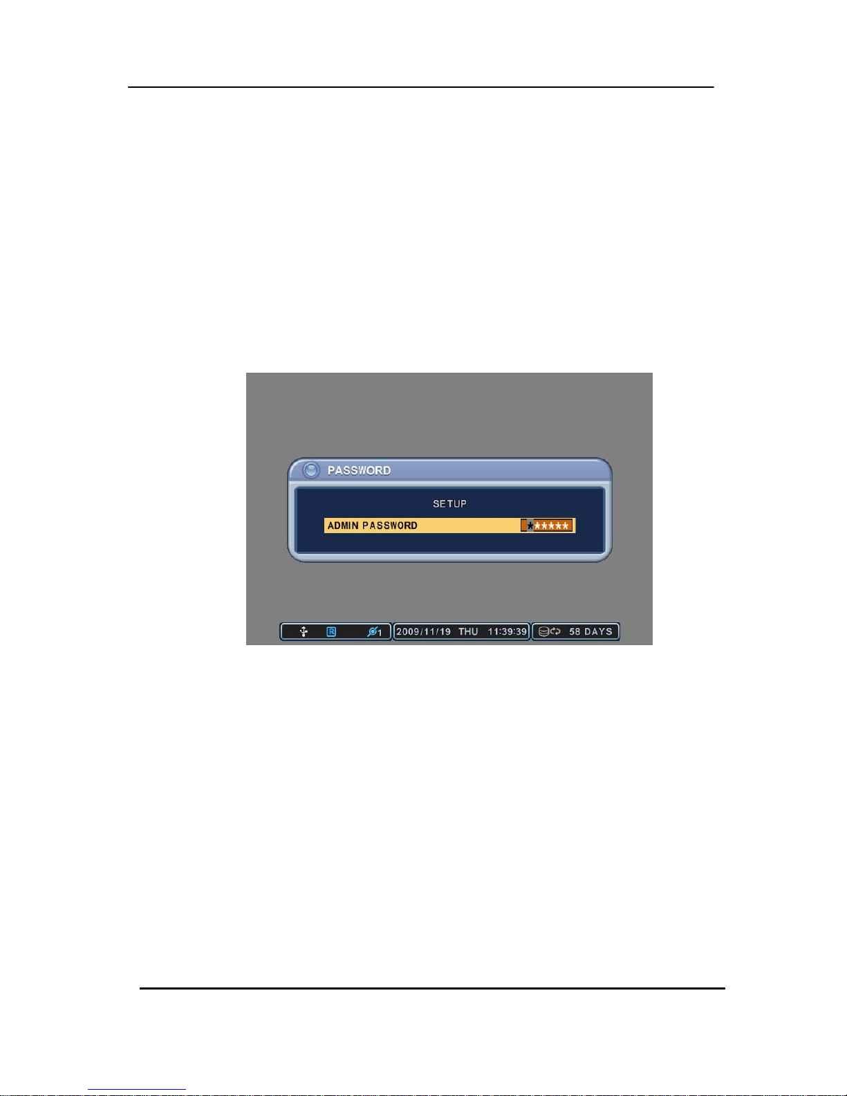
2) Enter the password using Numeric buttons when prompted for a password.
<The Factory Default password for the unit is “000000”>
3) Press [MENU] button to display the QUICK SETUP screen.
4) QUCIK SETUP menu appears once a password is entered.
5) Use Directional buttons to select menu and press [ENTER] button to confirm.
Page 18
17 DIGITAL VIDE O REC ORDER
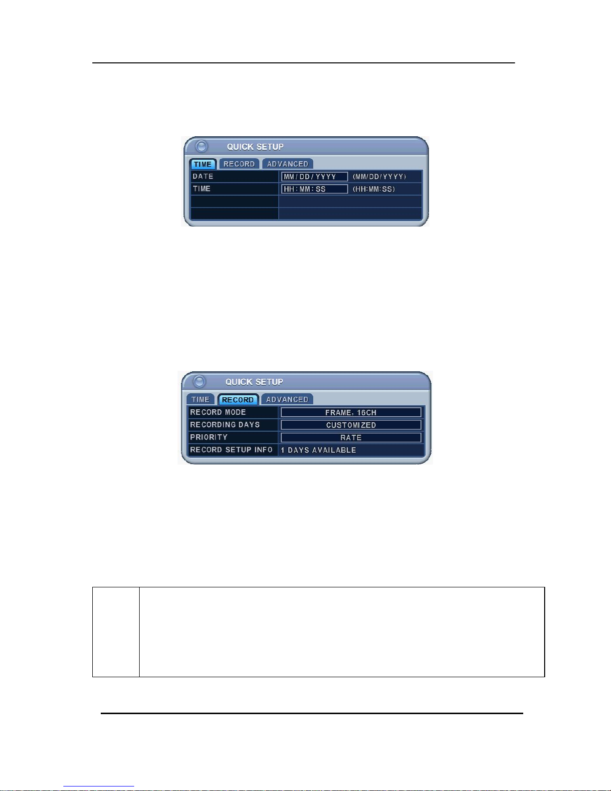
1. TIME
When the Digital Video Recorder is powered on for the very first time, it is important to set
the exact date and time.,
1) Select “Time” on TAP menu by using Directional buttons.
2) Enter the Date and Time by pressing numeric buttons on the remote controller
or “–/+” on the unit.
3) Press [ENTER] button to exit a menu with saving changes. Press [ESC] to exit a
menu without making changes.
2. RECORD
This is an easy setup for recording.
2-1. RECORD MODE
1) Select “RECORD MODE” on TAP menu by using Directional buttons.
2) Select MODE by pressing “–/+” buttons on the remote controller or on the unit.
3) Press [ENTER] button to exit a menu with saving changes. Press [ESC] to exit a
menu without making changes.
RECORD
MODE
• CIF, 4/8/16Ch: Each channel records at CIF resolution at same rate: 360x240(360x288).
• Field, 4/8/16Ch : Each channel records at Field resolution at same rate: 720x240(720x288).
• Frame, 4/8/16Ch:Each channel records at Frame resolution at same rate: 720x480(720x576)
•Frame + CIF:
Channel number 1 - 720x480(720x576)+Channel number 2~16 - : 360x240(360x280)
Page 19
18 DIGITAL VIDE O REC ORDER
2.2. RECORD DAYS
1) Select RECORDING DAYS by pressing “–/+” buttons on the remote controller or on
the unit.
2) Press [ENTER] button to exit a menu with saving changes. Press [ESC] to exit a
menu without making changes.
2.3. PRIORITY
1) Select “RATE” or “QAULITY by pressing “–/+” buttons on the remote controller or on
the unit.
2) “RATE” : DVR is set up with high recording speed mode automatically.
3) “QUALITY” : DVR is set up with high picture quality mode automatically. .
2.4 RECORD SETUP INFO
This displays the picture quality and recording speed.
NOTE
1. START RECORDING
: When setup is finished, press [REC] button on the front panel or on the
remote controller to start recording,
2. For individual recording setup of each channel and more specified setup,
enter into RECORD in main menu.
Please refer to 3. ADVANCED for how to enter into main menu.
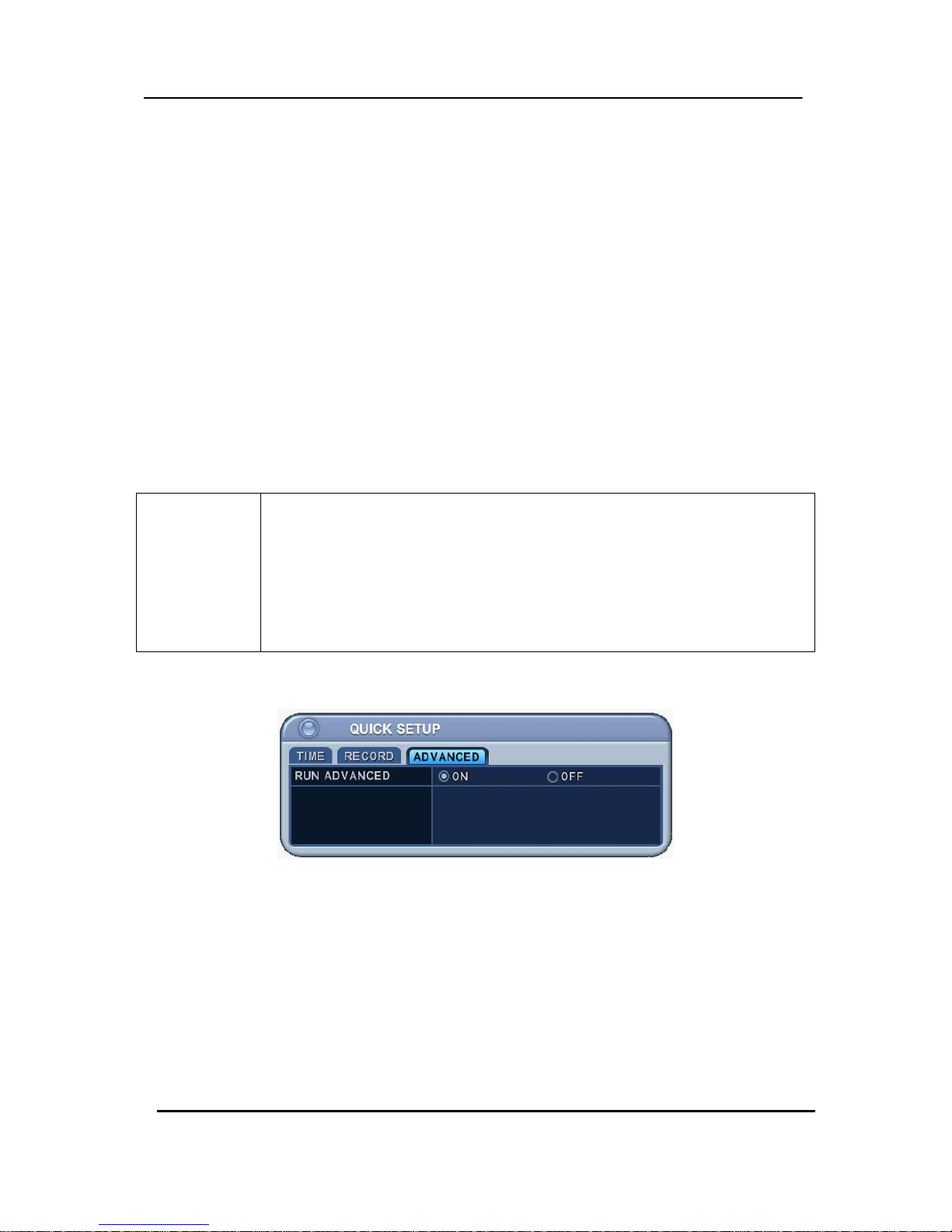
3. ADVANCED
Select “ON” or “OFF” by pressing “–/+” buttons on the remote controller or on the unit.
1) “ON” : Select this to enter into main menu and press [ENTER] button to exit a menu
with saving changes.
z Escape from “QUICK SETUP” menu by pressing “ESC” button.*
z Press MENU button again to enter into MAIN MENU.
2) “OFF” : Select this to stay on “QUICK SETUP” menu.
3) To resume Quick SETUP menu from Main Menu, refer to 2-1 DISPLAY SETUP part
in manual
Page 20
19 DIGITAL VIDE O REC ORDER
IV.LIVE VIEWING
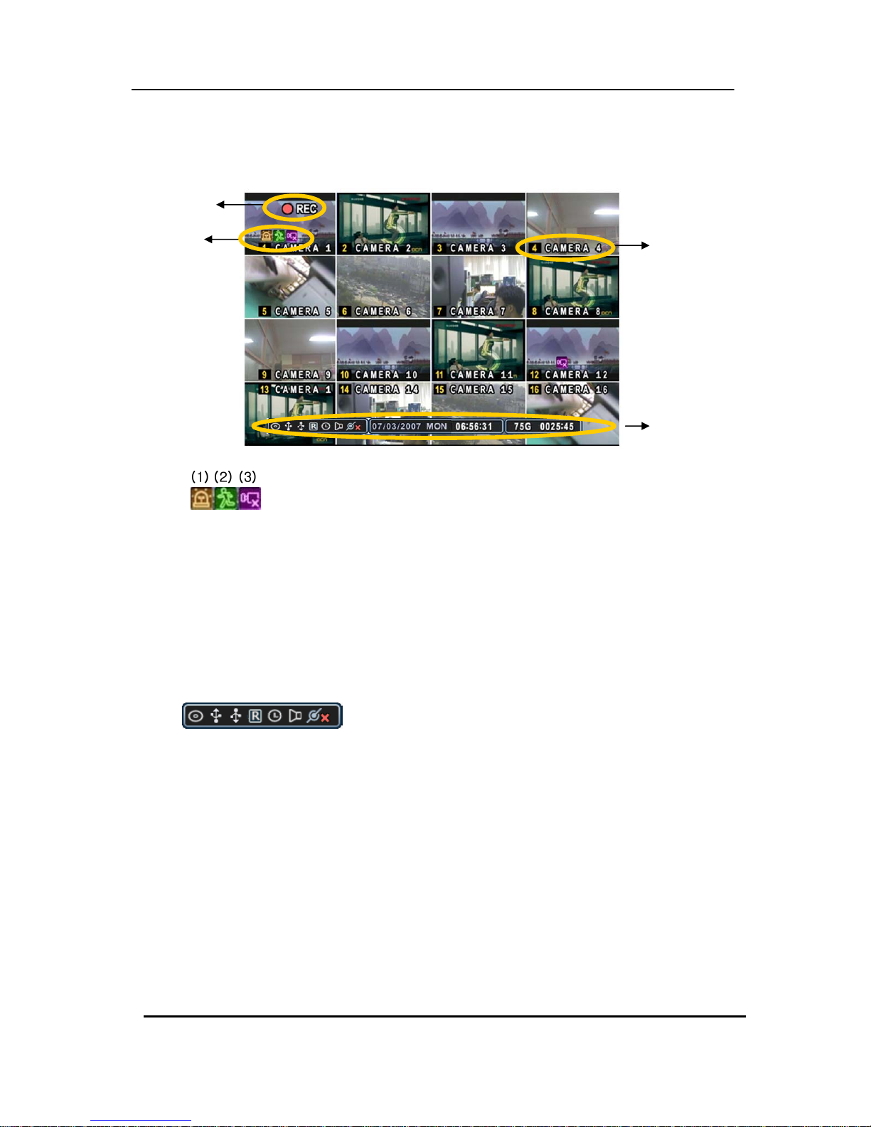
1. Display Overview
1.
(1) Indicate Alarm In terminal is triggered by an alarm sensor. To disappear, press
[CANCEL/ESC] button on remote controller or [CLR] button on the front panel.
(2) Indicate Motion detected. To disappear, press [CANCEL/ESC] button on remote
controller or [CLR] button on the front panel.
(3) Indicate Video Loss during Recording. To disappear, press [CANCEL/ESC] button on
remote controller or [CLR] button on the front panel.
(1) (2) (3) (4) (5) (6) (7)
2.
(1) Indicate Built-in CD R/W is connected. It’s changed to blue color while it’s doing backup.
(2) Indicate an USB Device is connected on Back panel. It’s changed to blue color while
it’s doing backup
(3) Indicate an USB Device is connected on Front panel. It’s changed to blue color while
it’s doing backup
(4) Indicate the DVR is recording now.
(5) Indicate Schedule Record mode is on. It’s changed to blue color when Schedule Record
starts.
(6) Indicate Audio Data is stored the selected time during playback and turn to blue color.
(7) It shows Number of Client, which is connected to Network.(MAX:3)
Recording Mode
Event Indicator
Status
Camera No and Title
Page 21

20 DIGITAL VIDE O REC ORDER
3. : Displays Year, Month, Time and Date.
4. : Show you the remaining recording time of the DVR. If remaining HDD
capacity is less than 4GB, this blue “Recycling” icon will be shown up.
2. Multi screen Display and Sequencing
2.1 Full Screen Display
Select any camera for Full screen display by pressing the Number button of the desired
camera.
2.2 Multi screen Display and Sequencing Display.
Press [DISPLAY] buttons to activate the multi screen display. It is changed the order as
shown below among your choice of SPLIT MODE. While in 16-way screen display, press
[DISPLAY] buttons for 1second to begin full screen sequencing. The sequence mode and
dwell times are programmable. For detailed information about configuring those, see
“Sequence Setup”. If the sequence mode is not activated, it moves to Quad mode instead
of Sequencing.
Page 22

21 DIGITAL VIDE O REC ORDER
2.3 Repositioning
To reposition a camera view on screen,
2.3.1. Virtual Remote controller
①
Press button on virtual remote controller by using mouse, then Mark will be
displayed on screen.
Move icon to the desired position by pressing directional buttons on remote
controller or virtual control pad.
② Press a Numeric button to reposition the selected camera. Press [Enter] button to exit here with
saving changes.
2.3.2. Remote controller
: Press
(EXT.SEARCH) button on remote controller, then Mark will be displayed
on screen.
2.3.3. Mouse
: Drag the selected camera to the position you wish to reposition by using mouse.
Page 23

22 DIGITAL VIDE O REC ORDER
3. Zooming
During live view mode or playback, it is possible to zoom into a section of the screen to get a
close-up view of the screen.
1. To activate the digital zoom, select the full screen display of the camera you wish to
zoom.
2. Then press the [ZOOM] button on IR Remote controller. Zoom area box pops up, as
shown below.
3. Move the box to the desired position using Direction [
] buttons.
4. Press [+] button to enlarge the image. Press [ - ] button to zoom out the image.
5. Press [CANCEL] button to return normal mode.
<Note>
If the Zoom button is pressed while in a multi-screen display, zoom operation is not
activated.
4. Spot Monitor
In addition to the Main Monitor, attaching a Spot Monitor enables user to monitor specific
channels independently form the main monitor
y Press [Spot] button on the remote controller, then press number button you wish watch as
full screen.
y Press [Spot] button twice to auto switch cameras. Sequence interval can be set from the
Sequential Setup.
y When an alarm has been triggered, that specific channel will go into Full Screen.
x 2 x 4
Page 24

23 DIGITAL VIDE O REC ORDER
5. HDMI output
To select video resolution of HDMI out put
y Press [1] + [LOG] button together on the front for more 5 seconds, then resolution will be
changed [ 1024 x 768 -Æ1280 x 720P Æ1920 x 1080I ] in order.
Page 25

24 DIGITAL VIDE O REC ORDER
V. OPERATION
1. Main Menu Overview
When the DVR is powered on, Live Viewing screen will appear after initialization about 30sec.
Press [MENU] button to access the main menu. An Admin Password Box will appear. Enter
the password using Numeric buttons on IR remote controller or CH increase button on Front
Panel. Default password is ‘000000’. Main Menu appears after proper password entered,
shown as below.
<Note> Factory default Admin/user password is [000000]. It is recommended to change the
“PASSWORD” when you install the DVR. Refer to [System Setup].
1.
Use Direction buttons [ ] to select the desired menu. Items selected in the menu are
represented in color.
2. Press [ENTER] button to select the menu and display Sub-Menu. Use Left/ Right buttons [
] to
select on TAP menu.
Selected items changed into [ORANGE] color.
* It is automatically saved changes when you move between TAP menus.
3. Press [ENTER] button to exit a menu with saving changes.
Press [CANCEL] to exit a menu without changes.
Selected Not selected
Page 26

25 DIGITAL VIDE O REC ORDER
2. Display Option
2.1. Display Setup
1. Use Direction buttons [
] to select “DISPLAY” menu. Then, press [ENTER]
button to display “DISPLAY SETUP”.
2. Use Left/Right buttons [
] to select on TAP menu ( ).
Selected items changed [ORANGE] color..
3. Use Down [T] button to specify.
4. Use [-, +] button to change the values
ITEM ADJUSTMENT
STATUS BAR
y Select “Show” or “Hide” below status bar on Main Monitor.
CAMERA y Select On-Screen-Display information for Camera Number and Title.
BORDER LINE
y Select Board Line between cameras.
[WHITE Æ GRAY Æ DARK GRAY Æ BLACK]
BACKGROUND
y Select Background color on NO VIDEO status.
[GRAY Æ DARK GRA Y Æ BLACK Æ BLUE Æ WHITE]
SPLIT MODE
y
Display is changed the order as shown below among your choice of SPLIT
MODE.
QUICK SETUP
ySelect “On” to resume “Quick SETUP” menu and “Off” to stay on main
menu setup.
5. Save changes and exit the menu, press [ENTER] button.
Exit the menu without making changes, press [CANCEL] button.
Page 27

26 DIGITAL VIDE O REC ORDER
2.2. Sequential Setup (Auto Sequence)
ITEM DEFAULT ADJUSTMENT
DWELL TIME
2 Sec y Specify the dwell time of each camera or Multi screen mode is
displayed. Use
[-, +] button : [1 second ~ 30 second]
SEQ. MODE None y Select desired sequence mode to switching.
FULL SCREEN
ALL y Select the cameras to be included or excluded from the
automatic sequencing.
Page 28

27 DIGITAL VIDE O REC ORDER
3. Camera Setup
1. Use Direction buttons [ ] to select “CAMERA” menu. Then, press [ENTER] button to
display “CAMERA”.
2. Use Left/Right buttons [
] or Number button to select the Camera you wish to configure.
3. Use Down [T] button to move specified menu and use Left/Right buttons [WX] to
select other item.
4. Use [-, +] button to change the value.
ITEM DEFAULT ADJUSTMENT
BRIGHTNESS 50%
y The brightness of each camera can be adjusted by pressing [-,+] buttons.
CONTRAST 50%
y The contrast of each camera can be adjusted by pressing [-,+] buttons.
COLOR 50%
y The color of each camera can be adjusted by pressing [-,+] buttons.
SENSITIVITY 10
y Level 1: Low sensitivity~ Level 20: High sensitivity.
MOTION GRID
y Use this menu to setup Zones for the motion detection The screen shown below
will overlay the current video image.
y Motion zones are set by on – it’s covered as cross stripes Screen.
y It is divided into 16 Grid and selected by Number button on IR Remote.
y : Select All.
y : : Cover All.
y Motion detected zones will be changed to BLUE Color.
Page 29

28 DIGITAL VIDE O REC ORDER
y USE Numeric button to select Motion Grid. GRAY Will be cleared. Or Use <+>
button to select Motion Grid at Front Panel. Running Man Icon
will be
activated. <+> button is used for selecting and cancel. Use <-> button to escape
from Grid Menu.
y It is also possible to select smaller motion grids for more precise motion
detection by using CMS.
COVERT
No
y If the Covert Mode is “YES”. Selected camera is invisible from all live displays,
playback and Network while continuing to record. Covert cameras are viewable
after change into “NO” .
TITLE
Camera #
y A combination of 12 digits and alphabets can be entered to label each camera.
Press appropriate Numeric button to type camera title. It’s up to 12 characters.
See Next chart.
P/T/Z ID/MODEL
None
Camera No
y Select P/TZ camera model to control.
ySelect appropriated channel for the PTZ camera. Camera ID means Camera
address.
5. Save changes and exit the menu, press [ENTER] button.
Exit the menu without making changes, press [CANCEL] button.
Motion Detected zones
Page 30

29 DIGITAL VIDE O REC ORDER
No
1st
Press
2nd
Press
3rd
Press
4th
Press
No
1st
Press
2nd
Press
3rd
Press
4th
Press
1 A B C 1 7 S T U 7
2 D E F 2 8 V W X 8
3 G H I 3 9 Y Z @ 9
4 J K L 4 0 . - _ 0
5 M N O 5 10+ SPACE
6 P Q R 6
<Insert characters from IR Remote Controller >
Page 31

30 DIGITAL VIDE O REC ORDER
4. Continuous Recording (Normal Recording)
The DVR comes with a certain preset settings from the factory. Therefore once the
DVR is installed, immediate recording is possible after pressing the record buttons. By
default, audio alarm, motion recording are off.
1. Use Direction buttons [ ] to select “RECORD” menu. Then, press [ENTER] button to
display “RECORD”.
2. Use Direction buttons [
] to select the Camera you wish to configure.
3. Use [-, +] button to change the value.
ITEM ADJUSTMENT
RATE
y Select recording speed for each camera.
: Recording resolutions is changed to Frame, Field and CIF mode.
<Refer to System >
QUALITY
y Specify the record picture quality for each camera.
ULTRA Æ SUPER Æ HIGH Æ MIDDLE ÆLOW
MOTION
ySelect Motion Recording ON or OFF. Camera does not record under normal
conditions. It is discussed on EVENT Section.
ALARM
ySelect Alarm Recording ON or OFF. Camera does not record under normal
conditions. It is discussed on EVENT Section.
<Note> Press [MENU] button on each Item at first line to apply all setting for the rest channel.
5. Save changes and exit the menu, press [ENTER] button.
6. Press [REC] button. Then, the red REC LED lights on the front panel and recording starts.
7. To Record stop, press the “ STOP” button on IR remote or on Front Panel.
Page 32

31 DIGITAL VIDE O REC ORDER
< Approximate File Size>
Quality NTSC PAL
UNIT
720x480 720x240 360x240 720x576 720x288 360x288
LOW 5.1 3.2 2.0 6.1 3.8 2.4 KB
MIDDLE 7.2 4.5 2.8 8.6 5.4 3.4 KB
HIGH 10.
2
6.4 4 12.
3
7.7 4.8 KB
SUPER 15.4 9.6 6 18.4 11.5 7.2 KB
ULTRA 24.6 15.4 9.6 29.5 18.4 11.5 KB
* It is calculated by theoretical, therefore it may be different depends on Video Signals or
other conditions in actual.
Page 33

32 DIGITAL VIDE O REC ORDER
5. Schedule Recording
The schedule chart shows a graphical representation of the defined record mode: Mode1~4.
However, the schedules are only displayed if a corresponding schedule has been
configured in the schedule menu.
1. Use Direction buttons [STWX] to select “SCHEDULE” menu. Then, press
[ENTER] button to display “Schedule Chart”.
2. Use Left/Right buttons [WX] to select on TAP menu
(
).
3. Use Down button [T] to select any Day you wish to configure.
It breaks down the days of the week in eight different categories: ALL, SUN, MON, TUE,
WED, THU, FRI and SAT. ALL is for everyday of the week. Daily schedule has priority to ALL.
4. Press [Enter] button you wish to configure. The detailed menu pops up for selected
Day, as shown below.
5. Enter the beginning and end time, then select Record mode to record.
(1) BEGIN: The time of recording start.
(2) END: The time of recording end. The ending time must not be before the starting
time or the same as the starting time. It must be any time over the starting time.
(3) MODE: Up to 4 different recording modes can be pre-determined for schedule
recording. (MODE1 ~ MODE4)
Page 34

33 DIGITAL VIDE O REC ORDER
6. Define modes below.
* Refer to Basic Recording for set up
<Note>
y The recording time is set by 24H(00:00 - 23:59). You need to set 2 days if the setting is over one
day.
D/W BEGIN END MODE
Monday 18:00 23:59 MODE 1
Tuesday 00:00 08:59 MODE 1
y The recording would not start when Ending time is ahead of Start time.
EX)
D/W BEGIN END MODE
Monday 18:00 08:59 MODE 1
7. To activate the schedule recording after setting, press the SCHEDULE button.
The SCHEDULE indicator illuminates. When a program covers the current time, the
REC indicator illuminates and the unit begins recording. Please note that if there
are no schedules configured, then the DVR will not record.
8. When the scheduled recording time is over, the REC indicator goes off and
recording stops.
9. If you wish to stop recording while scheduled recording, press the SCHDULE
button, then the SCHEDULE indicator goes off and the Schedule Recording Mode
is released.
Page 35

34 DIGITAL VIDE O REC ORDER
6. Event
1. Use Direction buttons [
] to select “EVENT” menu. Then, press [ENTER] button to
display “EVENT”.
2. Use Direction buttons [
] to select the Camera you wish to configure.
3. Use [-, +] button to change the value.
In this section, users may set different event recording set up to select frame and image
quality by each camera.
Page 36

35 DIGITAL VIDE O REC ORDER
7. Device
The menus are displayed with options on the left-hand column and settings in the right hand
column. A cursor (highlighted menu) can be moved using the Direction buttons [
] .
7.1 GENERAL
ITEM ADJUSTMENT
POST RECORD
TIME
y Determines the duration of the DVR continues record after Event detect.
[10SEC ~ 300 SEC ]. By default 10 sec.
AUDIO RECORD
y Select audio recording device usage: ON or OFF.
(Audio 1 ~ Audio 4 : Ch 1 ~ Ch 4)
The audio data is always recorded in real time unlike the video data
that can be recorded in various modes including real time. There may
be a slight delay in synchronization of the audio to video
KEYPAD MODEL y Select Joystick Controller and Baud Rate.
KEY TONE
y By default, the DVR emits a beep every time a button is pressed. Set
the key tone to off to turn button beep off. Default by “ON”
KEY SENSITIVITY
y The sensitivity of touch buttons on front panel can be controlled in
this setting.
Page 37

36 DIGITAL VIDE O REC ORDER
7.2 ALARM
ITEM ADJUSTMENT
RECORD
CAMERA
y ALL: Start to record All Alarm “ON” channel if there is any Alarm
signal is triggered.
y 1:1: Start to record the channel, which Alarm is triggered.
ALARM BUZZER
y ON: The buzzer Sounds if an alarm is triggered. The buzzer will
sound for the duration of the RECORD TIME. This buzzer related with
Alarm Out. Please configure Alarm Out “ON” for Alarm buzzer.
yOFF: Disables the ALARM BUZZER function.
ALARM OUT1~2
y Configure which relay will be triggered when an alarm is activated
per camera. Select from four available options:
Video Loss, Motion, Alarm ALL, Each Alarm, System.
y Press [Cancel] button to stop Alarm Out.
It will be cleared by an order: Alarm>Motion> Video Loss
INPUT
Change the input type. Use [-, +] button to change the values.
2. Save changes and exit the menu, press Enter button.
Exit the menu without making changes, press [CANCEL] button.
<Note> If “System” is selected, the relay will be triggered when System
has problems such as HDD FAIL, Power loss etc.
<Note> Press [-] button to stop the buzzer immediately. Stopping the
buzzer does not stop the alarm recording.
Page 38

37 DIGITAL VIDE O REC ORDER
8. Network Setup
The static service consists of an IP address that remains constant for the duration of the contract of
the internet service, whereas the dynamic service consists of an IP address that frequently changes
every time a new connection is made through the provided modem, or recurrently in a given period of
time. Though most internet service providers offer both solutions, this manual will distinguish the two
solutions according to the commonly available service type to configure the DVR for the networking
purposes.
8.1. IP setup
1. Use Direction buttons [ ] to select “NETWORK” menu.
Then, press [ENTER] button to display “Network”.
2. Use Down button [
] to specify the detail.
3. Use [-, +] button to change the value.
4. Save changes and exit the menu, press [ENTER] button.
Exit the menu without making changes, press [CANCEL] button
ITEM ADJUSTMENT
CONFIG
y STATIC IP: Edit IP address, Gateway and Netmask.
y DHCP: Dynamic Host Configuration Protocol.
It is automatically set on from Local DHCP if there is Local DHCP server (i.e. The
local Router) . if the DHCP is set to ON, the IP address, Gateway and subnet Mask
will be assigned by DHCP server.(i.e.The local area network Router)
IP Address y Enter the static IP address
Net mask y Enter the IP address of subnet mask.
Gateway y Enter the IP address for the internet gateway server.
DNS Server y Verify the name of the domain name system
PORT
y Select “0000 ~ 9999”
Enter the port number that the client will use to communicate with the DVR
over the internet. The default port is 7000.
It is recommended to use over 1,000.
Page 39

38 DIGITAL VIDE O REC ORDER
8.2. E-Mail
This DVR allows you to specify the events that generate notification. Sends e-mail
notification if an event occurs such as alarm or motion is detected and so forth.
The mail server can use either the DVR mail server or your existing e-mail settings.
The menus are displayed with options on the left-hand column and settings in the right hand
column. A cursor (highlighted menu) can be moved using the Direction buttons [
] .
ITEM
ADJUSTMENT
USE
OFF
y Select the e-mail notification on or off. The default is off.
Default
y Default it is provided by manufacture. Mail notification options and mail
address settings are available.
SMTP
y SMTP Configuration TAP will be activated to set up your own mail
settings.
SMTP
Server
y Enter the e-mail server name or IP. To server name, using the virtual
keyboard, or pressing appropriate Numeric button on IR Remote or front
panel.
PORT
y Define the port that the SMTP server will communicate through. By
default, it set to 25.
AUTH y Check this <on> if your mail server requires authentication.
USER ID
Password
y Enter the user ID/name and password for the SMTP Server.
(It is recognized as a small letter, even it’s displayed as a Capital Letter).
E-mail Address y 5 mail address can be configured for mail notification.
Page 40

39 DIGITAL VIDE O REC ORDER
8.3 DDNS
This DVR offers free dynamic DNS update. It keeps track of your changing IP address. It’s
easiest to use.
The menus are displayed with options on the left-hand column and settings in the right hand
column. A cursor (highlighted menu) can be moved using the Direction buttons [
] .
ITEM ADJUSTMENT
USE
y OFF : NO use of DDNS
y DEFAULT : Default it is provided by manufacture. We offer DDNS service
for remote at http://www.dvrhost.com
If you are using <Default> for DDNS, you do not need to setup anything.
It’s not allow to you create host name. It’s providing by DVR. Press [info]
button on IR remote or Front panel, then check your host name.
For example, http://G51D3D4.dvrhost.com:9000
y DYNDNS : To use your own domain name service or “dyndns.com”
Domain Name y Enter the name you set for the DDNS web configuration.
User ID y Enter your user ID.
Password y Enter your password.
DDNS Test y Click the button to confirm the connection. A success message will appear.
ON
Page 41

40 DIGITAL VIDE O REC ORDER
8.4. Router & Port Forwarding
The majority of any network will often consist of a single IP address which shares the internet
access through a router. This IP address may be any external (public) static IP address or
any dynamic IP address issued by the Internet Service Provider.
The purpose of a router is to enable multiple personal computers and any other devices that
require internet connection to access the internet simultaneously. Most routers by default
enable (open) commonly used ports so that mainstream applications such as Hypertext
Transfer Protocol (HTTP, Port 80), File Transfer Protocol (FTP, Port 21), Telnet (Port 23) and
Post Office Protocol 3 (POP3, Port 110) are used.
To solve the firewall problem and let visitor into the network, the user instructs the router to
allow traffic to pass through on a given port. This is known as Port Forwarding, as the router
forwards (directs) all internet requests on a specific port to the local machine. With port
forwarding, external visitors are able to connect to the DVR while other internal devices
remain protected.
Here is the example of DVR connection.
Network Router DVR IP Setting
PC Connect position PC Connect position
CF
① LAN ② WAN
A B C B C
Static IP
use
STATIC
○ △ X ★ ★
DHCP ○ ▲ X ☆ ★
Check the DVR IP of info
and set into Router.
x
STATIC
○ ○ ○ ○ ○
DHCP
N/A [Need Local DHCP
Server]
DHCP
use
STATIC ○ △ X ★ ★
DHCP ○ △ X ★ ★
Check the DVR IP of info
and set into Router
x
STATIC
N/A
DHCP △ △
PPPOE is not supported
Page 42

41 DIGITAL VIDE O REC ORDER
1) Description of Location.
A. LAN: Connect by Local IP. If you are connection from within your network, you only
need to enter the IP address of the system into the S/W (ex. 192.168.0.50)
B. WAN: Connect by DDNS. If you are connecting from outside your network, use the
DDNS to configure the S/W.(Ex. L123456.dvrhost.com).
C. WAN: Connect by IP address. If you are connecting from outside your network and if
you know your Static IP address , use the IP address to configure the S/W. (Ex.
http://124.137.23.72:6000
)
2) Description of Symbols.
○ : Connected.
x : Not able to connect
△: There’s some limitation depends on Router or Network connection
★ : Need to use Port Forwarding
3) Description of Color.
Yellow - Recommended
Grey - Non available
White – Depends on Router or Network condition.
2. How to use DVR for DHCP
<Note> Each Router has different port forwarding settings. Please refer to the router manual
or contact to your router manufacture for assistance.
Internet
: DHCP
DVR : DHCP
Router:
: Port Forwarding /DMZ
DVR : Static IP
Page 43

42 DIGITAL VIDE O REC ORDER
8.5. MISC.
ITEM ADJUSTMENT
BANDWIDTH
y Select the network bandwidth to limit the amout of network resources
allocated to client connection..The default is unlimited: “ 4 KBPS~ 8 MBPS”
Page 44

43 DIGITAL VIDE O REC ORDER
9. System Setup
9.1. General
1. Use Direction buttons [STWX] to select “SYSTEM” menu. Then, press [ENTER] button.
2. Use Left/Right buttons [WX] to select on TAP menu
3. Use Down button [T] to specify the detail.
4. Use [-, +] button to change the value.
5.
Save changes and exit the menu, press [ENTER] button.
Exit the menu without making changes, press [CANCEL] button.
ITEM ADJUSTMENT
SYSTEM ID
y To select the DVR to be controlled with the remote controller, press and hold
the DVR ID button. While holding the DVR ID button, press the appropriate
DVR ID number. For example, enter 05 for DVR ID 05, enter 43 for DVR ID
43, and such.
y Set the ID of IR controller on “00” to control DVRs at the same time,
whatever DVR ID are.
AUTO LOCK
yThe DVR locks all the buttons after three minutes of inactivity like a
Screensaver. The buttons can be unlocked with the user password. Default by
“OFF”.
RECORD MODE
yCIF, 4/8/16Ch: Default setting
The system records each camera individually and then multiplexes them.
Each channel records at CIF resolution: 360x240(360x288).
• Field, 4/8/16Ch: The system records each camera individually and then multiplexes
them. Each channel records at Field resolution: 720x240(720x288).
• Frame, 4/8/16Ch: The system records each camera individually and then multiplexes
them. Each channel records at Frame resolution: 720x480(720x576)
Page 45

44 DIGITAL VIDE O REC ORDER
• Frame + CIF : Channel number 1-720x480(720x576) + Channel number 2~ 4/8/16 - :
360x240(360x280)
PB DEINTERLACE
y ON: Reducing image flickering but less picture quality.
y OFF: Better picture quality for still image but having flicker for moving picture.
RUN ON BOOT
y This is the purpose to start REC without pressing REC button when you turn on.
PASSWORD
y if you choose “OFF”, The password window will not be shown except POWER/
SERVICE MENU/ RECORDING STOP/ SCHEDULE RECORDING STOP.
FACTORY
DEFAULT
• To restore factory default settings, stop recording and then execute “START” by using
ENTER button.
9.2. Time
ITEM ADJUSTMENT
DATE y Enter the Date
TIME y Enter the Time
TIME SYNC
If several DVRS are installed and connected via network, one of the DVRs or
PC may be set as the master clock. This unit will control the date and time for
all of the other units.
y ON: It is set as the Slave Clock.
y OFF(Default): Master Clock or The unit which does not use Time Sync Function.
TIME SERVER
y Enter the IP of Master clock DVR or PC when the unit is set as [ON] on Time
Sync Menu.
<note> Please STOP the recording before Time Setting.
Install “DVR TimeSynclnstller.exe “. It starts automatically.
The DVR will communicate though “UDP4014 Port” with Window for
TimeSync at every 10 sec.
Page 46

45 DIGITAL VIDE O REC ORDER
9.3. Account
Admin can define each user’s Authority. Select User 1~5 , then select Activate option on or
off. When enabled, it will be possible to check individually under user settings: Monitoring,
Playback, Back up, Network, Configuration (Main Menu Setup), Shutdown (Power off),
Record stop.
Enter the 6 numbers for the new password, and then re-enter the same password under
COMFIRM section. The asterisks will advance automatically as the numbers are entered.
Page 47

46 DIGITAL VIDE O REC ORDER
9.4. DISK
ITEM ADJUSTMENT
FORMAT
1. Stop the DVR completely before the disk format.
2. Use [-, +] button to change select device.
* Internal HDD
* USB – Memory Stick
* USB – CD/DVD-RW
* USB – HDD
<Note>
When you format USB-HDD, it is formatted to FAT 32 format type.
3. Use down button [T] to move
, then press [“+” or “ –“] button
to start formatting.
4. Formatting will begin, and the progress will be displayed at the bottom of the
window. Please not that it takes 10~30 seconds for format a HDD.
5. When formatting is finished, it will display COMPLETE, and also SUCCESS at
the bottom of the window.
OVERWRITE
Users may select the record policy of the system’s internal hard disk drive. By
default, the system’s hard disk drive is set to overwrite from the beginning when it
becomes full.
yON: By default, the hard disk drive will overwrite from the beginning when it
becomes full.
yOFF: It stops recording after HDD is full.
DISK MONITOR
y It stops automatically if HDD failure happens. It starts to “Monitoring” again after
DVR reboot . (Use [-, +] button to stop or start)
RECORD LIMIT
Allows you to configure when the DVR automatically deletes all data from HDD. It lefts the
data for below duration from current time.
[NONE Æ 12HOURS Æ 1DAY~ 6DAYS Æ 1WEEK ~ 4WEEKS -> 30 DAYS ]
Page 48

47 DIGITAL VIDE O REC ORDER
9.5. UPDATE.
1) Download the latest firmware file and copy to USB Flash memory stick in the Root Folder.
2) Turn on your DVR (If you are using, please stop the recording)
3) Plug USB memory stick into the front or rear USB port and check if USB icon shows up on the Status bar.
4) Move to upgrade menu and start upgrade by pressing [+]/[enter] button.
5) Wait until upgrade finished and show “Success” message, then Press [+] to restart.
Indicator CONDITION
H/W VERSION y Shows the Main PCB version of the system.
S/W VERSION y Shows the Software version of the system.
<NOTE>
1. Please make sure your USB Flash memory stick has enough space for update file size.
2. Do not make special folder into memory stick for these files.
3. Do not format the USB at window, just remove all files inside.
4. Do not switch OFF or PRESS any key during the upgrade process.
5. Please consult with your installer or seller before upgrade DVR.
Page 49

48 DIGITAL VIDE O REC ORDER
9.6. INFO
Press info button on IR remote to display the information. The other menu is blocked to
move. This menu provides information such as listed below.
Indicator CONDITION
LANGUAGE
y Display Current Language and you can change language here.
User cannot change Language while it’s under recording mode.
MODEL y Display Channel Number and compression.
HOSTNAME. y Display hostname and Mac Address.
MAC y Display MAC address
NETWORK y Shows the current IP and Port of this unit.
INTERNAL HDD yDisplays numbers of HDD and total HDD size .
USB (FRONT) y Displays what kind of device is connected to the front USB connector.
USB (REAR) y Displays what kind of device is connected to the rear USB connector.
IDE BUS 0
y Shows the Primary HDD status. A : Master, B: N/A
<note> It will be displayed when the HDD support S.M.A.R.T function. Please
change this HDD to NEW HDD in the case of “WARNING”.
** “ERROR” means the HDD damaged physically.
Page 50

49 DIGITAL VIDE O REC ORDER
VI.PAN/TILT ZOOM CONTROL
1. P.T. Z . Menu
1. To activate the Pan/Tilt Control, select the full screen display of the camera you wish
to control.
2.
Then press the [P/T/Z/FOCUS] button. Shortcut Menu box pops up, as shown below.
INDICATOR RESUL TING ACTIONS
[ENTER] Button
y Press this button to display “HELP” Menu. Press [ENTER] Button again, or
[CANCEL] button to cancel Help Menu.
[CANCEL] Button
y Press this button to cancel “PAN/TITL” Operation.
[MENU] Button
y PTZ camera control interface will be extended to use whole function. Press
this button again to make short-cut menu.
y To Tilt up and Down.
y To pan Right and Left.
y Zooming In and Out.
<Note > Please Refer to Help Menu for specific control.
Page 51

50 DIGITAL VIDE O REC ORDER
The layout of the PTZ interface conforms to the layout of the front of the DVR or the remote
controller. Menu button is the guide anchor position for all other buttons. When in PTZ
interface mode, all buttons used for the PTZ related operation.
** Please Check below items before using PTZ Camera.
1. RS 422/485 Connection, camera Jumper Setting and etc
2. Set the PTZ Camera ID & MODEL NO at the Display menu
2. Preset & Tour
Button Function
Set preset position; SPOT OUT on remote controller
Move the PTZ into desired location.
Press the Preset button.
Custom 1 will illuminate.
Set the # for the Preset location.
Press Enter to save and exit.
Go to preset position; INFO on remote controller
Press Go to button.
Enter the desired Preset # and press Enter.
Start Auto Tour; BACKUP on remote controller
Press Auto Tour Button.
Press the + button and enter the range of Preset and press Enter.
For Example, Auto Tour Button, +5 will start the tour of 1 ~ 5 presets of the
PTZ Camera
3. Custom Functions
Button Function
PTZ custom function 1; DISPLAY on remote controller
PTZ custom function 2; ZOOM on remote controller
PTZ custom function 3; P/T/Z on remote controller
Please refer to the PTZ manufacture’s instruction manual for proper jumper settings to match
the protocols to the DVR.
Page 52

51 DIGITAL VIDE O REC ORDER
4. PTZ Camera Model - PAN/TILT/ZOOM Camera List
# Model Name 3X Speed Preset Go to Tour A. Pan A.Tilt Pat Me
Esc/
Enter
1 NUVICO, NV 9600 BPS o o o o o o o o
2
MERIT LILIN, PIH-
7000/7600 o o o o o o o o
3 VCL, Orbiter Microsphere o o o o
4 SAMSUNG, SCC-641 o o o o o o o
5 NEC, NC-21D o o o o
6 SUNKWANG, SK2107 o o o o o
7 RESERVED o o o o o
8 D-MAX, PTZ PROTOCOL o o o o o o
9 LG, LPT-A100L P/T/Z o
10
HONEYWELL, GCC-
655N
11 WONWOO, PT-101 o
12~14 PELCO, D 2400~9600 o o o o o o o o
15 C&B TECH, AN200 o o o
16 CANON, VC-C4 o o o
17~19 PELCO, P 2400~9600 o o o o o o o o
20~22 PELCO, EP 2400~9600 o o o o
23
PANASONIC,
WV-CS/W85x,86x o o o o o o
24
HONEYWELL, HSDN-
251N/P o o o o
25
GE/KALATEL,
CyberDome o o o o o
26 DY ELEC, SmartDome o o o o o
27 BOSCH, TC8560/TC700 o o o o
28 SYSMANIA, ORX1000
29 AD, DELTADOME o o o o o
30 HUNT, HTZ-2300 o o o o o o
31 HAZEM, RESERVED o o o o
32 RVT, EZ Protocol o o o o o o o o
33 LG, MULTIX o o o o o
Page 53

52 DIGITAL VIDE O REC ORDER
34
ELMO,
PTC-200C/400C o o o o
35 NICECAM, MP-1xxx o o o o
36
C&B TECH, CNB-
PTZ102 o o o o o
37 IKEGAMI, PCS I-LAN o o o o o o o o
38 IKEGAMI, lCD I-LAN o o o
39 Reserved
40
TOA, SC80 SYSTEM
CONTROLLER o o o o o o o
41 TOSHIBA, SC1000 o o o o o o o o
42 BBV, TC 9600 BPS o o o o o o o
<Note> Speed has 0~8 steps
1 (Slow) – 8 (Fast)
* 0 – Keep Pressing the button to increase speed
Page 54

53 DIGITAL VIDE O REC ORDER
VII.SEARCH/ PLAYBACK
1. Time Search
1. To start playback, press [Time Search] button, Time search Calendar Menu
pops up, as shown below.
2. Use Left /Right button to change select Month on .
3. Use Up/Down buttons [ ] to select “DAY” on Calendar. Selected data will be shown as a
graphical representation of the recorded video stored on the DVR.
4.
Select “Hour and Minutes“ or ”the camera” you wish to playback. Then press [ENTER]
button.
5. Press [ENTER] button to start playback.
<Note> It will not be changed if there are no stored data on previous/next month.
<Note> The data are color-coded by category: Alarm(Red) > Motion(Green) > Normal (Yellow)
<Note>
Time : Mulitscreen Display
Camera : Full screen Display
Page 55

54 DIGITAL VIDE O REC ORDER
2. Log List Search/Alarm, Motion Search
The logs can be used to search and review directly to a point in time of the recorded data.
Alarm, motion, video loss and system related logs can be searched and played back directly
from the time of the incident.
1.
To start Event Search, press [Log] button on the front, then Log List Menu
pops up, as shown below.
MENU TAP CONDITION
ALL y It has a list of all the events since the initial power on procedure of DVR
SYSTEM y It shows All Event except for Alarm, Motion, and Video Loss.
NETWORK y It shows NETWORK List.
ALARM y It shows All Alarm List.
MOTION y It shows Motion List.
VIDEO LOSS y It shows Video Loss List.
2. Use Up/Down buttons [TS] to desired “Time” to playback. Use Left/Right buttons
[WX] to move NEXT page.
3. Press [ENTER] button to start playback.
<Note> Log list is saved on HDD.
<Note> To save log output, please connect USB memory stick into USB port on front. Then
press Display button on each category to backup Log data. USB Icon will be flashed as
Blue.
Page 56

55 DIGITAL VIDE O REC ORDER
VIII.BACKUP
1. USB Memory Stick Backup
1. Insert a USB Memory Stick into the USB connection port on the front panel.
<Note> Make sure your USB device has enough space before commencing backups.
2. Press [BACKUP] button on the front panel to display the backup menu.
3. Use [-, +] button to change select device: USB - Memory Stick.
4. Please select the data for BACKUP.
(1) NORMAL: Normal Recording Data
(2) ALARM: Alarm Recording Data
(3) MOTION: Motion Recording Data
The illustration to the left has selected ALL CAMERA, NORMAL, ALARM and
MOTION data.
5. Enter the numbers as required in 24-hour format, then move to .
6.
Press [ENTER] button to start BACKUP.
* USB icon will be highlighted in blue during the backup.
• If there is not enough space on your USB memory stick, the system will not proceed with
backup.
USB Memory Stick
z The backup progress indicator will be displayed at the bottom of the window. While
the system is in backup session, please do not perform playback.
7. After backup process is finished, USB icon will be highlighted in white.
Page 57

56 DIGITAL VIDE O REC ORDER
2. External USB HDD Backup
External USB-HDD is recognized within 10 seconds after plug in USB Connection cable to
UBS port in DVR.
2.1. Start to backup
1. Plug in USB connector into the USB connection port on the front panel.
2. Press [BACKUP] button to display the backup menu.
3. Use [-, +] button to change select device: USB – HDD
4. Please select the data for BACKUP.
A. NORMAL: Normal Recording Data
B. ALARM: Alarm Recording Data
C. MOTION: Motion Recording Data
The illustration to the left has selected ALL CAMERA, NORMAL, ALARM and
MOTION data.
5. Enter the numbers as required in 24-hour format, then move to .
6.
Press [ENTER] button to start BACKUP.
* USB icon will be highlighted in blue during the backup.
• If there is not enough space on your USB memory stick, the system will not proceed with
backup.
USB Memory Stick
z The backup progress indicator will be displayed at the bottom of the window. While
<Note>
z
You must stop all recording before performing backup to external USB HDD.
z
ONLY FAT 32 Format disk will be read through Window PC.
z
The data in FAT 32 format disk is not replayed on DVR. Format is discussed in
“SYSTEM>DISK” Section.
Page 58

57 DIGITAL VIDE O REC ORDER
the system is in backup session, please do not perform playback.
7. After backup process is finished, USB icon will be highlighted in white.
8.
When users get out of backup menu, the following message will be shown up to alert.
Page 59

58 DIGITAL VIDE O REC ORDER
3. CD/DVD –RW Backup
<Note>
z
You must stop all recording before performing backup to CD/DVD RW.
1. Plug in USB connector into the USB connection port on the front panel.
2. Press [BACKUP] button to display the backup menu.
1. Use [-, +] button to change select device: USB – CD/DVD-RW
2. Enter the numbers as required in 24-hour format, then move to
.
3. Press [ENTER] button to start BACKUP.
* USB icon will be highlighted in blue during the backup.
• If there is not enough space on your USB memory stick, the system will not proceed with backup.
USB Memory Stick
z The backup progress indicator will be displayed at the bottom of the window. While the system
is in backup session, please do not perform playback.
4. After backup process is finished, USB icon will be highlighted in white.
<Note>
z
For CD/DVD-RW back up, the select option is not available.
The data will be backed up to CD/DVD-RW of All cameras and normal, alarm,
motion recording together.
Page 60

59 DIGITAL VIDE O REC ORDER
4.How to Play Backup data in USB Memory Stick Backup
1. With “MCD Player”
- Plug a USB memory stick into your PC. No software installation is required.
2. Double Click on “MCD Player” in the window and will play as follows.
3. Back up data can be also be played by [LOCAL PLAYER]
Play
Playback
Stop
Watermark
Channel Select Display Select Capture
Page 61

60 DIGITAL VIDE O REC ORDER
5. Back up Range Setup
It is possible to set up backup range automatically on Time Search Menu[by Month, Date,
Hour, Minute]
Press [-] button to set backup Start time , press [+] button to set End. Selected time will be
changed [Light Grey] Color.
Selected backup time from 15:05~15:15 will be displayed on Backup range.
Page 62

61 DIGITAL VIDE O REC ORDER
Appendix 1: WEB SERVER
Enter the IP address of the unit in the address page
of the Internet Explorer.
For example, type in http://192.168.0.250:7000
Above illustrates example of a unit when it is utilizing
port 7000.
You can either sign in with: admin or user. Next
enter the password for the unit.
Click on Web Server to connect to the DVR
through IE browser
Page 63

62 DIGITAL VIDE O REC ORDER
Revised at Nov, 2009
Page 64

63 DIGITAL VIDE O REC ORDER
X.SPECIFICATIONATION
Specifications
4CH / 8CH / 16Ch
Video Input
4 , 8, 16
Video Output
HDMI, Composite, VGA, SPOT-OUT
Video Compression
H.264
Audio Compression
G.711
Live Display Resolution
NTSC 720*480, PAL 720*576
Alarm In/Out(Relay)
4ch - 4/1 , 8ch - 8/2 , 16ch - 16/2
Operating System
EMBEDDED LINUX
System Control
Key buttons, IR Remote Controller, Remote software(DVR Player), Mouse
Live Display Speed
Real Time
Maximum
NTSC
30 fps 720 x 480 ,60 fps 720 x 240, 120 fps 360 x 240
PAL
25 fps 720 x 576 ,50 fps 720 x 288, 100 fps 360 x 288
Audio Record(in/out)
4ch - 1/1 , 8ch - 4/1 , 16ch - 4/1
Features
Display
Brightness, Contrast, Color Adjustment Per Channel
Camera Title
12 Characters per Channel
Recording Mode
Continuous, Schedule, Alarm, Motion
Recording Method
5 Levels of Compression Rate / Record Frame Rate Adjustment
Motion Detection
Per Channel 4*4 Grids (SET)/ 28 x 24 (CLIENT)/ 20 Sensitivity Levels
Search Mode
Date & Time, Camera , Log search
Playback Modes
Forward & Reverse: Pause, Frame by Frame, Normal Speed, 2X, 4X, 8X, 16X
Multi-tasking
Simultaneous Live Display/ Playback, Record or Back-up, Remote Transmission
Watchdog
Power Failure Recovery: Auto Reboot / Maintaining Previous Record Settings
Watermark
Provided
Back Up
USB Flash Memory Stick, External HDD and External CD/DVD-RW
Interface
RS422/485, Ethernet(10/100 Base-T), USB 2.0
HDD
Up to 2 INTERNAL HDD
Network
LAN, WAN, Internet,
Remote
Client Software, Internet Explorer
Page 65

64 DIGITAL VIDE O REC ORDER
WEEE Symbol Information
Correct Disposal of This Product
(Waste Electrical & Electronic Equipment)
(Applicable in the European Union and other European countries with separate
collection systems)
This marking shown on the product or its literature, indicates, that it should not
be disposed with other household wastes at the end of its working life. To
prevent possible harm to the environment or human health from uncontrolled
waste disposal, please separate this from other types of wastes and recycle it
responsibly to promote the sustainable reuse of material resources.
Household users should contact either the retailer where they purchased this
product, or their local government office, for details of where and how they can
take this item for environmentally safe recycling.
Business users should contact their supplier and check the terms and
conditions of the purchase contract. This product should not be mixed with
other commercial wastes for disposal.
Page 66

65 DIGITAL VIDE O REC ORDER
<Memo>
 Loading...