

Page 1
Page 2
TROUBLESHOOTING
• Under
normal
operation
the LED should light w
hen the
furnace b
lower is r
unning
.
• Both lamps operate from the same multivoltage ballast.
he LED
If t
1. Check to be
2. Be sure lamp connectors
not light
does
sure there is
:
power to
are
fastened
the
unit.
securel
y.
3. If the LED still does not light, replace lamp(s).
f still
4. I
(Please
Use of
W
ARRANTY
The manufacturer warrants the GeneralAire GUV2000 air purification unit against defects in
materials and workmanship for a period of four (4) years from the date of installation. Lamps carry a
warranty for the useful life of the lamp, two (2) years . This warranty does not cover broken lamps
due to shipping, installation or handling.
also have other rights which vary from state to state.
operating, replace b
not
standard off-the-shelf lamps are
note
improper
lamps
will void
allast.
with
warrant
not compatible
y.)
This warranty gives you specific legal rights and you may
this
unit.
2
5/8”
18 3/4”
-C Lam
is
ide.
Lam
p
GUV
2000
Purifie
p
16” Germicidal UV-C
itanium
T
Photocatalytic
Reflector
16” Germicidal UV
Box
size
10.75 high
x
4.25 w
© 2005 For service please call 248-476-5100
Ai
Air flow
r
r
Furnace
Return
Air Duct
Page 3

G
ENERAL
A
IRE
GUV-2000
Multivoltage
Phototcatalytic
Air Purifier
Installation
Instruction
ACKING THE UNIT
UNP
Each GeneralAire GUV2000 Air Purifier unit i s
germicidal lamps placed
remove
portion of
“hot spots” which reduce lamp life. Handle by the porcelain caps or
use
soft
proper care must be taken when removing from packaging.
each
lamp from the tube taking care to not touch the glass
the
lamp with bare hands. Oils from the hands can cause
a soft
cloth. If you accidentally touch a lamp, wipe it off using
cloth
dampened w
Be sure all parts are included in the
ith
• GeneralAire
• Two 16” Germicida
• Four Sheet Metal Screws and two
• Titanium Photocatalytic Reflector
• Installation & maintenance instructions
Maintenance
&
s
keps
with t he
tube)
nuts
shipped
in tubes with
rubbing alcohol. The lamp is fragile and
protective packaging. Carefully
following list:
GUV2000
Air Purifier
l L
amps (packed in
a
IMPORTANT SAFETY INSTRUCTIONS
When
should
1. READ AND FOLLOW ALL INSTRUCTIONS.
2. SAVE THESE
3.
4. The ultraviolet light
installing
always
Always be
Do not look directly at the
lamps, use UV-protected safety goggles.
and using this electrical
be followed including the
INSTRUCTIONS
the unit
sure
produced by the
is unplugged during installation or service procedures.
.
lamps.
equipment, basic safety precautions
following:
UV lamps is harmful to your
Should it become necessary to view the
eyes.
Page 4

INSTALLATION
• Best results are achieved when the unit is installed where the HV
Therefore,
install the
preferred installation is on
the
unit
on the
supply s
ide, k
eeping
the re
it as
turn side
far from
the f
of
the heat/cooling source a
AC system air temperature is most constant
urnace. If return
side installation i
s possible,
and in the main
s not possible,
airstream
.
.
• Do not locate the unit within 20” of any plastic material that will be directly exposed to the UV
a return side humidifier or certain types of air filters. Check with the filter manufacturer to see if their material is
UV
resistant. Over time, UV
• Do not t
which reduce lamp life. Handle either by the porcelain caps or use a soft cloth. If you accidentally touch a
lamp, wipe it off, using a soft cloth dampened with rubbing alcohol.
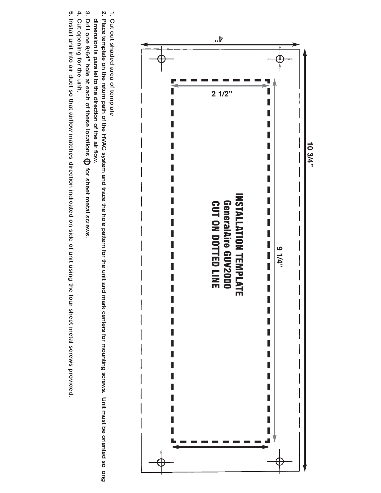
1.
Cut
2. Center
Trace the
ouch the g
opening indicated
out the
template on the l
hole
pattern for the unit
light will degrade many plastic materials.
lass portion of t
amps with
he l
bare hands because
by a dotted line on the installation template.
ongitudinal
axis
he plenum using tape
of t
and
oils from
hands
the
to hold
can
(See insert)
it in place.
light, such as
cause “
hot
spots”
mark centers for mounting screws.
(Photo A)
3. Cut opening f
sheet
metal screws.
4. Remove the cover
ize nut drive
s
retaining
or
the unit and
r to
r
nuts and
from
emove
set aside.
5. Attatch the titanium reactor panel to back of
an
unit as
(as indicated in
driver
inverted “V” to
and t
he
8-32 keps nuts package
photo A.) Use an 11/32 size nut
metal screws and fasten securely
6. Attach unit to air duct using the four
sheet metal screws provided.
drill 9/64” holes for
unit using an 11
the
top and bottom
the
maximize airflow
d w
ith
2
/3
sheet
8-32 keps nuts
Germicidal
Lamp
Holder
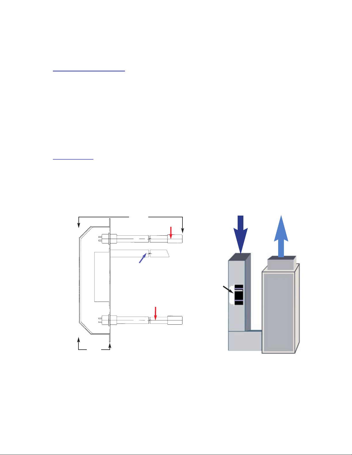
7. Remove germicidal lamp holder (Figure A)
using a 11/32 size nut driver.
8. Slide germicidal lamp into lamp opening.
9. Reinstall lamp holder.
10. Plug in lamp connector to the end of lamp.
11. Repeat steps 6 thru 9 for second lamp.
12. Replace the cover and secure using
the two retaining nuts.
(Figure
A)
Page 5

WIRING
Simply plug the unit into an 120 V
AC outlet and allow it to run continuously.
The multivoltage ballast i
self-adjusting and operates with voltages from 115 VAC through 277 VAC. For connecting to voltages higher than 120 volts AC remove plug and wire in accordance with local wiring codes.
MAINTENANCE
This m
conditions
the glass portion of the
aintenance
will dictate the f
schedule is only a
requency of cl
lamps with bare h
spots” which reduce lamp life. Handle either b
guideline, determined by
eaning
ands
and/or replacement of lamps. Do not
because oils from the
porcelain caps or
y the
average conditions. A
hands
u
can
se a s
cause “hot
oft
cloth. If
ctual
touch
you accidentally touch a lamp, wipe it off, using a soft cloth dampened with rubbing alcohol.
s
CLEANING THE
LAMPS -
REPLACING THE
Recommended interval: 1
LAMPS
-
Recommended interval: 24 months. (Follow procedure below excluding #6.)
1.
nplug the power cord from the outlet, or disconnect power to the unit
U
2. Remove the cover from the unit using a 1
remove the
3.
Unplug the lamp connector
4. Remove lamp holders using a 11/32 size nut driver.
5. Remove each lamp by grasping the porcelain cap and
extract carefully.
6.
Using a soft cloth moistened with rubbing alcohol, wipe down
each lamp. If there is a l
want to use a
7.
Slide one lamp back into lamp opening. Reinstall lamp holde
8. Repeat step 7 for second lamp.
9. Plug the lamp connector to the end of each lamp.
Replace and secure cover using the two retaining nuts.
10.
top and
can of air first.
bottom retaining
2 months (Follow procedure
1/32 size nut driver to
nuts .
from the end of each lamp.
(Figure A)
arge build-up of dust particles, you may
Always
handle
lamps by end caps.
below)
.
r.
11. Plug power cord back into outlet, or restore power to
Please note standard off-the-shelf lamps are not compatible w
Use of improper lamps will void warranty.
unit.
ith this
u
nit.
 Loading...