

Page 1

SETUP & OPERATION MANUAL
FEATURES
New! Upper and lower blade guard
assembly helps prevent unintentional or
accidental hand/finger contact with the
saw blade
New! Switch protection device to prevent
accidental or unintentional start-up of the
saw.
New! Dust collector table kit for direct
dust-extraction hook-up.
Head tilts 30° (EX-16) / 38° (EX-21 & EX30)
left and 45° right, tilting the blade, not the
table keeping the workpiece level for better control & more accurate cuts.
2" cutting thickness capacity.
Quick blade changes with finger
operated blade clamps, no tools
required.
Easy access speed and tension controls.
Onboard dust blower.
EX-16
16" throat capacity. Large 12” x 18 1/2”
(305 x 470 mm) table surface.
EX-21
21" throat capacity. Large 13 1/2” x 23 1/2”
(345 x 597 mm) table surface. Organized
blade storage on base.
EX-30
30" throat capacity. Large 14” x 32 1/2”
(358 x 825 mm) table surface. Organized
blade storage on base.
SCROLL SAW
SPECIFICATIONS
LENGTH
27” (686 mm) - EX-16
32” (812 mm) - EX-21
43 1/4" (1100 mm) - EX-30
WIDTH
15” (380 mm) - EX-16 & EX-21
15 1/2” (394 mm) - EX-30
HEIGHT
17” (432 mm) - EX-16
15” (380 mm) - EX-21
15 1/4” (387 mm) - EX-30
BLADE TILT RANGE
30° (LEFT) TO 45° (RIGHT) - EX-16
38° (LEFT) TO 45° (RIGHT) - EX-21 & EX-30
THROAT
16”(406 mm) - EX-16
21”(535 mm) - EX-21
30”(762 mm) - EX-30
MAXIMUM CUTTING DEPTH
2” (51 mm)
SPEED (VARIABLE)
400 TO 1400 STROKES/MIN - EX-16
400 TO 1550 STROKES/MIN - EX-21 & EX-30
TABLE SURFACE
12” x 18 1/2” (305 x 470 mm) - EX-16
13 1/2” x 23 1/2” (345 x 597 mm) - EX-21
14” x 32 1/2” (358 x 825 mm) - EX-30
MOTOR
120 V, 1.3 A
WEIGHT
54 LBS (24.5 kg) - EX-16
65 LBS (29.5 kg) - EX-21
97 LBS (44 kg) - EX-30
MODELS
#EX-16
#EX-21
#EX-30
(MODEL #EX-21 SHOWN)
VERSION 8_ REVISION 2 - MAY 05/13
(S/N: EX-16: 22018213 / EX-21: 22053213 / EX-30: 32231913)
© COPYRIGHT GENERAL INTERNATIONAL 05/2013
Page 2

GENERAL® INTERNATIONAL
8360 Champ-d’Eau, Montreal (Quebec) Canada H1P 1Y3
Telephone (514) 326-1161 • Fax (514) 326-5555 • www.general.ca
THANK YOU for choosing this Excalibur by General
®
International Scroll Saw
model. This scroll saw has been carefully tested and inspected before shipment and if properly used and maintained, will provide you with years of reliable service. For your safety, as well
as to ensure optimum performance and trouble-free operation, and to get the most from your
investment, please take the time to read this manual before assembling, installing and operating the unit
The manual’s purpose is to familiarize you with the safe operation, basic function, and features
of this scroll saw as well as the set-up, maintenance and identification of its parts and components. This manual is not intended as a substitute for formal woodworking instruction, nor to
offer the user instruction in the craft of woodworking.If you are not sure about the safety of performing a certain operation or procedure, do not proceed until you can confirm, from knowledgeable and qualified sources, that it is safe to do so.
Once you’ve read through these instructions, keep this manual handy for future reference.
Disclaimer: The information and specifications in this
manual pertain to the unit as it was supplied from the
factory at the time of printing. Because we are committed to making constant improvements, General
national reserves the right to make changes to components, parts or features of this unit as deemed necessary,
without prior notice and without obligation to install any
such changes on previously delivered units. Reasonable
care is taken at the factory to ensure that the specifications and information in this manual corresponds with
®
Inter-
that of the unit with which it was supplied. However, special orders and “after factory” modifications may render
some or all information in this manual inapplicable to
your machine. Further, as several generations of this
model of sroll saw and several versions of this manual
may be in circulation, if you own an earlier or later version of this unit, this manual may not depict your unit
exactly. If you have any doubts or questions contact
your retailer or our support line with the model and serial number of your unit for clarification.
Page 3

GENERAL®& GENERAL®INTERNATIONAL WARRANTY
All component parts of General®, General® International and Excalibur by General
International ® products are carefully inspected during all stages of production and each unit
is thoroughly inspected upon completion of assembly.
Limited Lifetime Warranty
Because of our commitment to quality and customer satisfaction, General® and General®
International agree to repair or replace any part or component which upon examination,
proves to be defective in either workmanship or material to the original purchaser for the life
of the tool. However, the Limited Lifetime Warranty does not cover any product used for profes-
sional or commercial production purposes nor for industrial or educational applications. Such
cases are covered by our Standard 2-year Limited Warranty only. The Limited Lifetime Warranty
is also subject to the “Conditions and Exceptions” as listed below.
Standard 2-Year Limited Warranty
All products not covered by our lifetime warranty including products used in commercial,
industrial and educational applications are warranted for a period of 2 years (24 months) from
the date of purchase. General® and General® International agree to repair or replace any
part or component which upon examination, proves to be defective in either workmanship or
material to the original purchaser during this 2-year warranty period, subject to the “conditions
and exceptions” as listed below.
To file a Claim
To file a claim under our Standard 2-year Limited Warranty or under our Limited Lifetime
Warranty, all defective parts, components or machinery must be returned freight or postage
prepaid to General® International, or to a nearby distributor, repair center or other location
designated by General® International. For further details call our service department at 1-888949-1161 or your local distributor for assistance when filing your claim.
Along with the return of the product being claimed for warranty, a copy of the original proof
of purchase and a “letter of claim” must be included (a warranty claim form can also be used
and can be obtained, upon request, from General® International or an authorized distributor)
clearly stating the model and serial number of the unit (if applicable) and including an explanation of the complaint or presumed defect in material or workmanship.
CONDITIONS AND EXCEPTIONS:
This coverage is extended to the original purchaser only. Prior warranty registration is not
required but documented proof of purchase i.e. a copy of original sales invoice or receipt
showing the date and location of the purchase as well as the purchase price paid, must be
provided at the time of claim.
Warranty does not include failures, breakage or defects deemed after inspection by General®
or General® International to have been directly or indirectly caused by or resulting from;
improper use, or lack of or improper maintenance, misuse or abuse, negligence, accidents,
damage in handling or transport, or normal wear and tear of any generally considered consumable parts or components.
Repairs made without the written consent of General® Internationallwill void all warranty.
Page 4

TABLE OF CONTENTS
Rules for safe operation . . . . . . . . . . . . . . . . . . . . . . . . . . . . . . . . . . . . . . . . . . . . . . . . . . . . . . . . . . . . . . . . 5
AdditionalSafety Instructions for Scroll Saw . . . . . . . . . . . . . . . . . . . . . . . . . . . . . . . . . . . . . . . . . . . . . . . 6
Electrical requirements . . . . . . . . . . . . . . . . . . . . . . . . . . . . . . . . . . . . . . . . . . . . . . . . . . . . . . 7
rounding instructions . . . . . . . . . . . . . . . . . . . . . . . . . . . . . . . . . . . . . . . . . . . . . . . . . . . . . . . . . . . . . . . . . . . . . . . . . . . . . . . . . . . . 7
G
Extension cords. . . . . . . . . . . . . . . . . . . . . . . . . . . . . . . . . . . . . . . . . . . . . . . . . . . . . . . . . . . . . . . . . . . . . . . . . . . . . . . . . . . . . . . . . . . 7
Identificationof mainpartsand components . . . . . . . . . . . . . . . . . . . . . . . . . . . . . . . . . . . . . . . . . . . . . . . 8
Unpacking & Handling . . . . . . . . . . . . . . . . . . . . . . . . . . . . . . . . . . . . . . . . . . . . . . . . . . . . . . . 9
List of contents . . . . . . . . . . . . . . . . . . . . . . . . . . . . . . . . . . . . . . . . . . . . . . . . . . . . . . . . . . . . . . . . . . . . . . . . . . . . . . . . . . . . . . . . . . . 9
Handling . . . . . . . . . . . . . . . . . . . . . . . . . . . . . . . . . . . . . . . . . . . . . . . . . . . . . . . . . . . . . . . . . . . . . . . . . . . . . . . . . . . . . . . . . . . . . . . . 9
Installation & Assembly . . . . . . . . . . . . . . . . . . . . . . . . . . . . . . . . . . . . . . . . . . . . . . . . . . . . . . 9
Attaching the power cord . . . . . . . . . . . . . . . . . . . . . . . . . . . . . . . . . . . . . . . . . . . . . . . . . . . . . . . . . . . . . . . . . . . . . . . . . . . . . . . . . 9
Install the saw on a stable surface . . . . . . . . . . . . . . . . . . . . . . . . . . . . . . . . . . . . . . . . . . . . . . . . . . . . . . . . . . . . . . . . . . . . . . . . . 10
Attaching the leveling feet . . . . . . . . . . . . . . . . . . . . . . . . . . . . . . . . . . . . . . . . . . . . . . . . . . . . . . . . . . . . . . . . . . . . . . . . . . . . . . . . 10
Installing the optional stand. . . . . . . . . . . . . . . . . . . . . . . . . . . . . . . . . . . . . . . . . . . . . . . . . . . . . . . . . . . . . . . . . . . . . . . . . . . . . . . 10
Mounting to a work surface . . . . . . . . . . . . . . . . . . . . . . . . . . . . . . . . . . . . . . . . . . . . . . . . . . . . . . . . . . . . . . . . . . . . . . . . . . . . . . . 10
Dust collector outlet. . . . . . . . . . . . . . . . . . . . . . . . . . . . . . . . . . . . . . . . . . . . . . . . . . . . . . . . . . . . . . . . . . . . . . . . . . . . . . . . . . . . . . 11
Choosing & Installing a Saw Blade . . . . . . . . . . . . . . . . . . . . . . . . . . . . . . . . . . . . . . . . . . . . . . 11
Blade selection. . . . . . . . . . . . . . . . . . . . . . . . . . . . . . . . . . . . . . . . . . . . . . . . . . . . . . . . . . . . . . . . . . . . . . . . . . . . . . . . . . . . . . . . . . 11
Blade storage . . . . . . . . . . . . . . . . . . . . . . . . . . . . . . . . . . . . . . . . . . . . . . . . . . . . . . . . . . . . . . . . . . . . . . . . . . . . . . . . . . . . . . . . . . . 11
Installing or changing blades . . . . . . . . . . . . . . . . . . . . . . . . . . . . . . . . . . . . . . . . . . . . . . . . . . . . . . . . . . . . . . . . . . . . . . . . . . . . . 13
Operating Instructions . . . . . . . . . . . . . . . . . . . . . . . . . . . . . . . . . . . . . . . . . . . . . . . . . . . . . . 14
On/Off switch . . . . . . . . . . . . . . . . . . . . . . . . . . . . . . . . . . . . . . . . . . . . . . . . . . . . . . . . . . . . . . . . . . . . . . . . . . . . . . . . . . . . . . . . . . . 14
On/Off switch padlock . . . . . . . . . . . . . . . . . . . . . . . . . . . . . . . . . . . . . . . . . . . . . . . . . . . . . . . . . . . . . . . . . . . . . . . . . . . . . . . . . . . 14
Adjusting the blade speed. . . . . . . . . . . . . . . . . . . . . . . . . . . . . . . . . . . . . . . . . . . . . . . . . . . . . . . . . . . . . . . . . . . . . . . . . . . . . . . . 14
Adjusting the blower . . . . . . . . . . . . . . . . . . . . . . . . . . . . . . . . . . . . . . . . . . . . . . . . . . . . . . . . . . . . . . . . . . . . . . . . . . . . . . . . . . . . . 14
Workpiece hold-down. . . . . . . . . . . . . . . . . . . . . . . . . . . . . . . . . . . . . . . . . . . . . . . . . . . . . . . . . . . . . . . . . . . . . . . . . . . . . . . . . . . . 14
Basic 90º straight or curved cuts . . . . . . . . . . . . . . . . . . . . . . . . . . . . . . . . . . . . . . . . . . . . . . . . . . . . . . . . . . . . . . . . . . . . . . . . . . . 15
Fret cutting . . . . . . . . . . . . . . . . . . . . . . . . . . . . . . . . . . . . . . . . . . . . . . . . . . . . . . . . . . . . . . . . . . . . . . . . . . . . . . . . . . . . . . . . . . . . . 15
Angle or bevel cutting. . . . . . . . . . . . . . . . . . . . . . . . . . . . . . . . . . . . . . . . . . . . . . . . . . . . . . . . . . . . . . . . . . . . . . . . . . . . . . . . . . . . 17
Maintenance, Adjustments & Servicing . . . . . . . . . . . . . . . . . . . . . . . . . . . . . . . . . . . . . . . . . . 17
Blade clamping thumbscrews/set screws . . . . . . . . . . . . . . . . . . . . . . . . . . . . . . . . . . . . . . . . . . . . . . . . . . . . . . . . . . . . . . . . . . . 17
Blade tension lever lubrication . . . . . . . . . . . . . . . . . . . . . . . . . . . . . . . . . . . . . . . . . . . . . . . . . . . . . . . . . . . . . . . . . . . . . . . . . . . . 18
Blade tension lever replacement . . . . . . . . . . . . . . . . . . . . . . . . . . . . . . . . . . . . . . . . . . . . . . . . . . . . . . . . . . . . . . . . . . . . . . . . . . 18
Upper arm adjustment for fret work . . . . . . . . . . . . . . . . . . . . . . . . . . . . . . . . . . . . . . . . . . . . . . . . . . . . . . . . . . . . . . . . . . . . . . . . 18
Squaring the blade to the table . . . . . . . . . . . . . . . . . . . . . . . . . . . . . . . . . . . . . . . . . . . . . . . . . . . . . . . . . . . . . . . . . . . . . . . . . . . 18
Maintenance . . . . . . . . . . . . . . . . . . . . . . . . . . . . . . . . . . . . . . . . . . . . . . . . . . . . . . . . . . . . . . . . . . . . . . . . . . . . . . . . . . . . . . . . . . . 19
Recommended Optional Accessories. . . . . . . . . . . . . . . . . . . . . . . . . . . . . . . . . . . . . . . . . . . . . . . . . . . . 19
Parts list & diagrams . . . . . . . . . . . . . . . . . . . . . . . . . . . . . . . . . . . . . . . . . . . . . . . . . . . . . . . . . . . . . . 20-25
Page 5

Rules for Safe Operation
To help ensure safe operation, please take a moment to learn the machine’s applications and limitations, as well as potential hazards. General® International disclaims any real or implied warranty and
old itself harmless for any injury that may result from the improper use of its equipment.
h
1. Be sure to read, understand and follow all safety
arnings and instructions in the supplied
w
Operator’s Manual.
. Do not operate the saw when tired, distracted, or
2
under the effects of drugs, alcohol or any medication that impairs reflexes or alertness. Stay alert!
Give your work your undivided attention.
3. Keep the work area well lit, clean and free of
debris. Cluttered areas and benches invite injuries.
4. Keep children and shop visitors at a safe distance
while operating the saw; do not permit them to
operate the scroll saw.
5. Childproof and tamper proof your shop and all
machinery with locks, padlocks, master electrical
switches and switch keys, or by removing starter
keys to prevent unauthorized or unsupervised use.
6. Fine particulate dust is a carcinogen that can be
hazardous to health. Work in well ventilated area
and use a dust collector whenever possible.
7. Wear approved safety glasses, dust mask and non-
skid footwear. Do not wear loose clothing, gloves,
bracelets, necklaces or jewellery while operating
the saw. Keep long hair contained by wearing protective hair covering.
8. Be sure all adjustment tools, wrenches or other clut-
ter are removed from the machine and/or the
table surface before operation. When not in use,
tools should be locked-up in a dry place, out of
children’s reach and away from flammable substances.
9. Keep hands well away from saw blade and all
moving parts. Use a brush,not hands, to clear away
chips and sawdust.
10. Be sure that saw blade is properly installed, and in
proper cutting direction, before operation. Always
use a clean,properly sharpened blade. Dirty or dull
blades are unsafe and can lead to accidents. Also,
be sure the blade has gained full operating speed
before beginning to cut.
11. Do not push or force stock into the blade. The saw
will perform better and more safely when working
at the rate for which it was designed. Do not use for
purposes not intended.
12. Avoid working from awkward or off balance positions. Do not overreach while cutting; keep both
eet on floor. Never lean over or reach behind the
f
blade and never pull the workpiece through the cut
from behind.
13. Never stand or lean on the saw.Serious injury could
occur if the unit is tipped over or if the blade is unintentionally contacted.
14. Use of parts and accessories NOT recommended
by General® International may result in equipment
malfunction or risk of injury.
15. Never leave the machine unattended while running or with the power “ON”. Don't leave tool until it
comes to a complete stop.
16. Always turn off and disconnect from power source
before servicing or changing accessories, blades,
bits, and cutters, or before performing any maintenance or adjustments.
17. Reduce the risk of unintentional start-up. Make
sure that switch is in the "OFF" position before
plugging in the power cord. Do not use the saw if
the power switch is defected. Have defective switches replaced by an authorized service center.
18. Make sure saw is properly grounded. If equipped
with a 3-prong plug it should be used with a threepole receptacle. Never remove the third prong.
Avoid body contact with grounded surfaces (e.g.
pipes, radiators, stoves, refrigerators).
19. Repairs to the saw should only be carried out by
qualified people using original spare parts. A
guard or other damaged part should be properly
repaired or replaced by an authorized service
center.
20. Inspect power cords and extension wires periodically. If damaged, have them repaired by an
authorized service facility. Never yank cords and
wires and keep away from heat, oil, and sharp
edges.
21. This tool is for indoor use only. Do not expose to rain
or use in wet or damp locations.
5
Page 6
Additional Safety Instructions
Specific to this Scroll Saw
B
ecause each shop situation is unique, no list of safety guidelines can ever be complete. The most
i
mportant safety feature in any shop is the knowledge and good judgement of the user. Use com-
mon sense and always keep safety considerations, as they apply to your individual shop situation
first and foremost in mind. If you have any doubts about the safety of an operation you are about
to perform: STOP! Do not perform the operation until you have validated from qualified individuals
if the operation is safe to perform and what is the safest method to perform it.
1. Material hold-down must be properly set and
remain in position during use.
2. Never reach under the table when operating or
make any adjustments while the scroll saw is running.
3. Secure the saw to the work bench with clamps or
mounting hardware.
4. Where possible, use clamps or a vice to secure your
workpiece. It is safer than using your hand.
5. Do not lift or carry the saw by the upper arm.
6. Make sure blade tension is properly adjusted.
7. Avoid awkward hand positions where a sudden slip
could cause a hand to move into the saw blade.
Do not place fingers or hands in the path of the saw
blade.
8. When removing short workpieces, or cleaning up
around the table, be sure that the switch is in the
OFF position and that the blade has come to a
complete stop.
9. Never turn the saw ON before making sure that the
table is clear except for the workpiece and related
feed or support devices for the operation planned.
10. Check for proper blade size and type.
12. Turn off motor if the material resists being backed
out of an incomplete cut. Use appropriate speed
for applications.
13. CAUTION: Some wood contains preservatives such
as copper chromium arsenate (CCA) which can
be toxic. When cutting these materials, extra care
should be taken to avoid inhalation and to minimize skin contact.
14. Always use a dust mask and safety glasses when
sawing. Everyday eyeglasses only have impact
resistant lenses, they are NOT safety glasses.
15. Keep guards in place and in working order.
16. Make sure your fingers do not contact the terminals
of the power cord plug when plugging in or unplugging the saw.
17. Never overfeed or force work into the blade.
18. Check for alignment and binding of all moving
parts, broken parts, mounting and any other conditions that may affect the saw’s operation.
19. Keep handles dry and free from oil and grease.
20. MAINTAIN TOOLS WITH CARE. Keep tools sharp and
clean for best and safest performance. Follow
instructions for lubricating and changing acces
sories.
11. Do not attempt to saw stock that does not have a
flat surface unless a suitable support is used.
TO AVOID ELECTRICAL SHOCK, ENSURE MACHINE IS PROPERLY GROUNDED. DO NOT OPERATE IN DAMP
CONDITIONS. DISCONNECT FROM POWER SUPPLY BEFORE SERVICING. REPLACE FUSE WITH THE SAME
TYPE AND RATING ONLY - 3 AMP.
BE SURE TO READ AND UNDERSTAND OWNER’S MANUAL BEFORE OPERATING.
6
21. DIRECTION OF FEED. Feed work into a blade or cut
ter against the direction of rotation of the blade or
cutter only.
Page 7
ELECTRICAL REQUIREMENTS
BEFORE CONNECTING THE MACHINE TO THE POWER SOURCE, VERIFY THAT THE VOLTAGE OF YOUR POWER SUPPLY CORRESPONDS WITH THE VOLTAGE SPECIFIED ON THE MOTOR I.D. NAMEPLATE. A POWER SOURCE WITH
GREATER VOLTAGE THAN NEEDED CAN RESULT IN SERIOUS INJURY TO THE USER AS WELL AS DAMAGE TO THE
MACHINE. IF IN DOUBT, CONTACT A QUALIFIED ELECTRICIAN BEFORE CONNECTING TO THE POWER SOURCE.
THIS TOOL IS FOR INDOOR USE ONLY. DO NOT EXPOSE TO RAIN OR USE IN WET OR DAMP LOCATIONS.
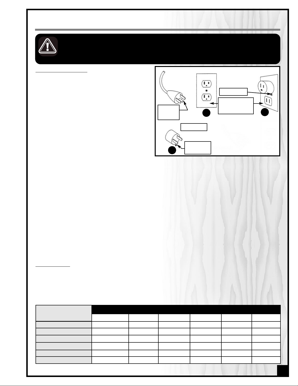
GROUNDING INSTRUCTIONS
n the event of an electrical malfunction or short circuit,
I
grounding reduces the risk of electric shock. The motor
of this machine is wired for 120V single phase operation and is equipped with a 3-conductor cord and a 3prong grounded plug to fit a grounded type receptacle, A.
Do not remove the 3rd prong (grounding pin) to make
it fit into an old 2-hole wall socket. If an adaptor plug is
used, B, it must be attached to the metal screw of the
receptacle.
Note: The use of an adaptor plug is illegal in some areas,
including Canada. Check your local codes.
Grounded, cord-connected tools intended for use on a
supply circuit having a nominal rating less than 150
volts: This tool is intended fo use on a circuit that has an
outlet that looks like the one illustrated in A. The tool has
a grounding plug that looks like the plug illustrated in
A. A temporary adapter, which looks like the addapter illustrated in B and C, may be used to connect this plug to
a 2 pole receptacle as shown in B if a properly grounded outlet is not available. The temporary adapter should be
used only until a properly grounded outlet can be insalled by a qualified electrician. This adapter is not permitted
in Canada. The green-colored rigid ear, lug and the like, extending from the adapter, must be connected to a permanent ground such as a properly grounded outlet box.
This tool is equipped with an electric cord having an equipment-grounding conductor and a grounding plug. The
plug must be plugged into a matching outlet that is properly installed and grounded in accordance with all local
codes and ordinances.
Improper connection of the equipment-grounding conductor can result in a risk of electric shock. The conductor
with insulation having an outer surface that is green with or without yellow stripes is the equipment-grounding conductor.If repair or replacement of the electric cord or plug is necessary, do not connect the equipment-grounding
conductor to a live terminal.uter surface that is green with or without yellow stripes is the equipment-grounding conductor.If repair or replacement of the electric cord or plug is necessary, do not connect the equipment-grounding
conductor to a live terminal.
DO NOT MODIFY THE PLUG PROVIDED.
If it will not fit your receptacle, have the proper receptacle installed by a qualified electrician.
CHECK with a qualified electrician or service person if you do not completely understand these grounding instructions, or if you are not sure the tool is properly grounded.
Grounding
Pin
C
Grounding methods
A
Adapter
Grounding
mean
Metal screw
Cover of Ground
outlet box
B
EXTENSION CORDS
USE ONLY 3-WIRE EXTENSION CORDS THAT HAVE 3-PRONG GROUNDING PLUGS AND 3-POLE RECEPTACLES THAT ACCEPT
THE TOOLS’ PLUG. REPAIR OR REPLACE A DAMAGED OR WORN POWER CORD OR PLUG IMMEDIATELY
If you find it necessary to use an extension cord with your machine make sure the cord rating is suitable for the
amperage listed on the motor I.D. plate. An undersized cord will cause a drop in line voltage resulting in loss of
power and overheating. The accompanying chart shows the correct size extension cord to be used based on cord
length and motor I.D. plate amp rating. If in doubt, use the next heavier gauge. The smaller the number the heavier
the gauge.
AMPERES
(AMPS)
25 Feet 50 Feet 75 Feet 100 Feet 150 Feet 200 Feet
EXTE NSI ON CORD LENGTH
< 5 16 16 16 14 12 12
5 à 8 16 16 14 12 10 NR
8 à 12 14 14 12 10 NR NR
12 à 15 12 12 10 10 NR NR
15 à 20 10 10 10 NR NR NR
21 à 30 10 NR NR NR NR NR
*Based on limiting the line voltage drop to 5V at 150% of the rated amperes. NR = Not Recommended
7
Page 8
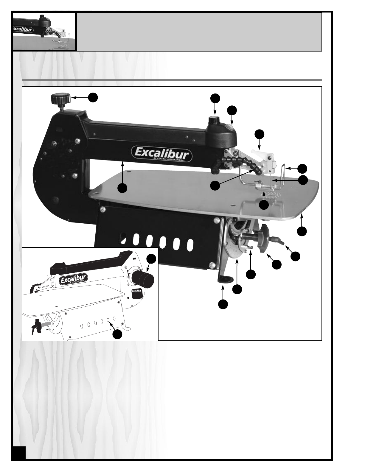
SCROLL SAW
X-16, EX-21 or EX-30
E
IDENTIFICATION OF MAIN PARTS AND COMPONENTS
(EX-21- shown)
A
B
C
D
E
OPPOSITE SIDE VIEW
Q
O
N
G
P
J
K
L
M
F
H
I
A- UPPER ARM ADJUSTER
B- VARIABLE BLADE SPEED CONTROL KNOB
C- ON/OFF SWITCH (WITH SAFETY DEVICE)
D- BLADE TENSION LEVER
E- BLADE GUARD
F- BLADE
G- WORKPIECE HOLD DOWN
H- TABLE
I- BLADE TILT LOCKING LEVER
8
J- TILT HANDLE
K- ANGLE INDICATOR
L- ANGLE ADJUSTMENT SCALE
M- MOUNTING HOLES (4)
N- BLOWER
O- UPPER ARM
P- MOTOR
Q- BLADE HOLDER SOCKETS
(EX-21 & EX-30 ONLY)
Page 9

UNPACKING & HANDLING
Carefully unpack and remove the scroll saw and its
components from the box and check for damaged
or missing items as per the list of contents below.
NOTE: Please report any damaged or missing items to
your General International distributor immediately.
LIST OF CONTENTS QTY
A - SCROLL SAW..............................................................1
B - POWER CORD ...........................................................1
C - HEX NUT .....................................................................8
D - LEVELING FOOT.........................................................4
E - 3 MM ALLEN KEY.......................................................1
F - BLADE.........................................................................1
NOTE: Unscrew the 4 shipping bolts and remove the saw
from the protective plywood shipping base.
HANDLING
A
(E
X
-
21-
sh
o
w
n)
C
E
B
F
D
Never lift the saw by the upper arm assembly as this will
result in damage to the drivetrain.
Rather lift the saw by the front of the table and by the
motor.
INSTALLATION & ASSEMBLY
For your convenience this scroll saw is shipped from the factory partially assembled and requires only minimal
assembly and set-up before being put into service.
ATTACHING THE POWER CORD
Plug the female end of the power cord into the socket
at the rear of the saw as shown.
BEFORE STARTING THE ASSEMBLY, MAKE SURE
THAT THE SWITCH IS IN THE “OFF” POSITION
AND THAT THE POWER CORD IS UNPLUGGED.
DO NOT PLUG IN OR TURN ON THE SCROLL
SAW UNTIL YOU HAVE COMPLETED THE ASSEMBLY AND INSTALLATION STEPS DESCRIBED IN
THIS SECTION OF THE MANUAL.
9
Page 10

INSTALL THE SAW ON A STABLE SURFACE
The unit should be installed on a flat, sturdy and stable
surface able to support the weight of the machine and
the workpiece with ease.
ATTACHING THE LEVELING FEET
A
B
Install the leveling feet as shown. Loosen the upper A
and lower B nuts as needed to adjust the height of the
foot.
Never install the machine over the edge of a table or
orkbench.
w
INSTALLING THE OPTIONAL STAND
If you prefer, an optional stand (item EX-21BS for EX-16
& EX-21 or item EX-30BS for EX-30) is available from your
local General International dealer. The stand is equipped with mounting holes allowing the saw, after removing the leveling feet, to be bolted directly to the
stand.
FOR YOUR SAFETY IT IS ESSENTIAL THAT THE MACHINE DOES NOT ROCK OR TIP DURING OPERATION. UPON STARTUP OR DURING OPERATION, IF YOU NOTICE ANY ROCKING, TIPPING OR CHATTERING OF THE BASE TURN THE
MACHINE OFF IMMEDIATELY AND READJUST THE LEVELING FEET AS NEEDED TO STABILIZE THE SCROLL SAW ON THE
BENCH OR WORK SURFACE
MOUNTING TO A WORK SURFACE
If a permanent shop placement is practical, consider
removing the leveling feet on the base and drilling
matchingthrough holes in the mounting surface of your
workbench or stand to bolt the saw in place (hardware
not included) on your workbench.
If a permanent installation is not practical, clamps can
also be used to secure the saw to a bench or work
table.
10
A
E F
C
D
G
B
ORDER OF ASSEMBLY
A- Saw
B- Hex head bolt
C- Flat washer
D- Workbench or stand
E- Flat washer
F- Lock washer
G- Hex nut
Page 11

UST COLLECTOR OUTLET
D
The dust collector outlet on this saw allows for hook-up
to a user supplied shop vacuum or dust collector.
Note 1: The dust collector outlet reduces clearance under
the table, and limits the left tilt capacity of the saw to 30º
(for model EX-16, and to 38º for models EX-21 and EX-30).
Note 2: If desired, the dust collector outlet can be
removed to recover a maximum left tilt capacity of 45º.
roceed as follows:
P
With the saw turned off and unplugged, loosen and
remove the 4 screws and washers A that attaches the
dust colllector outlet to the underside of the table
ALWAYS TURN OFF AND UNPLUG THE MACHINE BEFORE REMOVING OR INSTALLING ANY COMPONANT.
A
CHOOSING & INSTALLING A SAW BLADE
BLADE SELECTION
Blade selection is dependent on the type and thickness of the material being cut, but is also a matter of experience and personal preference. There are numerous types of blades available on the market specifically suited
for various cutting applications such as metal-cutting and spiral blades which cut in all directions.
Try test-cutting with a sample of each to determine which blade works best for you with different materials.
Replacement and specialty blades can be purchased from a variety of sources. Ask your local tool or scroll saw
dealer for suggestions for unpinned 5” scroll saw blades
Some general guidelines to consider when choosing blades:
• Wide, thick blades with coarse teeth are suited to cutting straight lines and sweeping curves, but will not turn
tight corners. They will cut aggressively and leave a fairly smooth finish, but may leave burn marks if the work
piece is turned too tightly.
• Narrower, thinner blades with finer teeth will cut more slowly, but will turn much tighter corners for cutting very
intricate work. They will impart a very smooth, burnished finish that requires no sanding.
• Consider material thickness when selecting blades. Ensure that a minimum of two or three teeth are in con-
tact with the workpiece at all times. For example, when cutting 1/8” thick material, use a blade with a minimum of of 16 20 teeth per inch.
Blade Storage (for models EX21 & EX-30 only):
There are sockets (mounting holes) on either side of the
base of the saw to hold blade storage “test tubes” (tubes
not supplied). Most blade retailers sell blades either
already in the tubes or will be able to sell spare tubes
separately. Storing your spare blades in tubes, by size,
right on the base of the machine can be a great way to
organize your spare blades so that they are handy and
available when needed.
based on what is available in your area.
11
Page 12

SKIP TOOTH
Regular evenly spaced tooth pattern. Considered the most common of scroll saw blades, they are available in
the widest range of sizes and provide a good combination of fast cutting action with good chip clearance
LADE
B
WIDTH THICKNESS TEETH/INCH
and a relatively smooth finish.
#2/0 .022 .010 28
#0 .024 .011 25
#2 .029 .012 20
#4 .035 .015 15
#5 .038 .016 12.5
#6 .041 .016 12.5
#7 .045 .017 11.5
#9 .053 .018 11.5
For extremely intricate sawing. Very tight cuts in 1/16” - 1/4”
wood veneer, plastic, hard rubber, pearl, etc.
For tight radius work with thin materials, 3/32” - 1/2” wood
veneer, wood, bone, fiber, plastic, etc.
For close radius work in materials 1/8” or thicker. Good for
sawing hard and soft woods, bone, horn, plastic, etc.
Popular sizes for cutting hard and soft woods, 3/16”
up to 2”. Also cuts plastic, paper, felt, bone, etc.
#11 .059 .019 9.5
#12 .062 .024 9.5
REVERSE TOOTH
Reverse teeth at the bottom of the blades prevent
splintering to the underside of the workpiece.
BLADE WIDTH THICKNESS TEETH/INCH
#2/0R .026 .011 28/20
#2R .029 .012 20/13
#5R .038 .016 12.5/9
#7R .049 .018 11.5/8
#9R .054 .019 11.5/8
#12R .062 .062 9.5/6
12
Same
applica-
tions as
Skip Tooth
blades.
DOUBLE TOOTH
Fast, clean cutting and very efficient
chip clearance.
BLADE WIDTH THICKNESS TEETH/INCH
#1D .026 .013 30
#3D .032 .014 23
#5D .038 .016 16
#7D .044 .018 13
#9D .053 .018 11
#12D .061 .022 10
Same
applica-
tions as
Skip Tooth
blades.
Page 13

INSTALLING OR CHANGING BLADES
ALWAYS TURN OFF AND UNPLUG THE MACHINE
BEFORE REMOVING, HANDLING OR CHANGING
BLADES.
1. Remove an installed, worn or broken blade by flip-
ping the blade tension lever forward (position 1), then
loosening the thumbscrews A and C on the upper
and lower blade mounts B and D.
2. Remove the blade.
. Verify that the upper arm is more or less parallel (with-
3
in 1/8”) to the saw table. If necessary, use the upper
arm adjuster K (below) to raise or lower the arm as
needed.
4. With the blade teeth facing forward and downward
slip the bottom of the blade down through the hole in
the table. Then slip the upper end of the blade into
the slot in the upper blade mount and position the
top of the blade above the set screw E but no higher
than the top of the shoulder F on the blade mount.
Then tighten the thumbscrew only enough to secure
the blade in the mount and prevent it from slipping
out.
5. The bottom portion of the blade may protrude be-
yond the bottom of the lower blade mount, this is
normal and will not affect performance. Only the upper portion of the blade requires proper positioning
in the upper blade mount.
Note: Overtightening the blade clamp thumbscrews can cause
premature wear to the blades gripping surface and result in blade
slippage or cause premature wear of the threads in the blade
clamp housing.
To avoid kinking or damaging the blade in the holder, G, when
making adjustments make sure the set screw H (opposite the
thumbscrew I) is threaded into the holder to protrude slightly
beyond the blade slot J.
6. Push the blade tension lever back (position 2) to apply
tension on the blade.
1
Upper arm must be parallel
(approx. 1/8”) to the table
G
A
2
B
C
D
F
E
Position
blade
between
these points
J
H
I
Helpful Hints on blade tension
Determining correct blade tension is somewhat subjective. It is learned through experience and is somewhat dependant on personal preference. A properly
LOWER
RAISE
K
tensioned blade will last longer and be much less likely to break prematurely. If the blade tension is too
loose, you will notice that the blade will have a tendency to drift or slip off-line when cutting and you may
also experience excessive vibration or unusual noise.
A blade that is too tight will break prematurely.
Assuming the blade has been properly installed in the
blade mounts, when the blade tension lever is pushed
fully back towards the rear of the saw, the blade should be properly tensioned.
Test the blade tension by lightly plucking on the blade, like you would a guitar string, with your finger. If the
blade is tight and tensioned correctly you will get a clear and even note. If so, you are ready to proceed to
operating and cutting with the saw. If not, for some cases after double checking that the blade is properly
installed in the blade mounts, further blade tension fine tuning can be made by adjusting the rear knob to raise
the upper arm slightly.
this knob as the primary blade tensioner will cause premature wear and damage to the machine.
Note: this is not the main function of the adjustment knob (see following paragraph) and using
This saw has an adjustment knob K in the rear that can raise the blade mount up to 1” (25 mm). This allows you
to fine tune blade tension when needed, as well as to reposition the saw blade at a point where you can use
a different part of the blade in the cutting area. This also allows you to use a piece of band saw blade, cut to
a length of 5”- 6” (127-150 mm) in your saw, and gives you up to 3 inch cutting capacity when needed.
Note: Do not over tension the knob as this can cause premature wear and damage to the machine.
13
Page 14

OPERATING INSTRUCTIONS
ON / OFF SWITCH
The saw is equipped with a simple dust protected rocker
style on/off switch A, featuring a protection device B to
revent unwanted or unintentional start-up
p
N / OFF SWITCH PADLOCK
O
To avoid accidental starting by young children or others
not qualified to use the tool, the use of a padlock C is
required.
. Open the padlock.
1
2. Insert through holes in the on/off switch.
3. Close the padlock.
4. Place the key in a safe place out of the reach of chil-
dren.
B
A
educe speed
r
ncrease speed
i
ADJUSTING THE BLADE SPEED
The Scroll Saw is equipped with a variable speed control
which allows you to select or fine-tune to the exact blade
speed required (from 400-1400 strokes per minute for the
EX-16 model & from 400-1550 strokes per minute for EX-21 &
EX-30 models) for best results based on the type and thickness of material and type of blade being used.
The blade speed control knob D is located on the top of
the machine.
• To increase blade speed, turn the control knob clockwise.
• To decrease blade speed turn the control knob counterclockwise.
Blade speed selection is subjective and is dependant on a variety of factors: type and thickness of material being
cut, type of blade being used, feed rate, required finish quality as well as experience,personal preference and comfort level of the user.There are no hard and fast rules. Be patient – practice and experience will be your best teacher.
Here are some general guidelines to consider when selecting/adjusting blade speed:
• For best results and smoothest most efficient cutting, always select the highest speed that you are comfortable
using based on your experience and skill level.
• Generally speaking, harder or denser workpiece material requires slower blade speeds.
• Slower speeds also work better with very thin blades, or when cutting most metals, as well as for brittle or delicate
material such as fine veneers.
• Some wood species will have a tendency to burn quicker at higher blade speeds. To avoid additional sanding
later, reduce blade speed and feed speed at the first signs of burn marks on the workpiece.
C
D
ADJUSTING THE BLOWER
The saw is equipped with a built-in blower to help clear cutting dust from the workpiece surface in front of the blade
and on any reference lines. Adjust the blower tube A as
needed to point the nozzle at the blade to set it at a comfortable distance so as not to obstruct your hand movement as you work.
C
WORKPIECE HOLD-DOWN
The workpiece hold-down B can be adjusted to assist in
preventing the blade from lifting the workpiece up from
the table during the cut. Loosen the thumbscrew C to set
the height to your convenience based on the thickness of
the workpiece. Before cutting, test to make sure that the
hold-down is not adjusted too tightly to the workpiece or
that it obstructs the movement of the workpiece.
A
B
14
Page 15

A
BASIC 90° STRAIGHT OR CURVED CUTS
All cuts made with the blade at 90° to the table follow the same basic principals. Start by marking or transferring
our pattern or reference lines onto you workpiece.
y
Maximum workpiece size from blade to rear of saw
The EX-16 has a 16” throat that allows for a
orkpiece of up to 16” of clearance to swing
w
ompletely around without hitting the back of
c
the saw. If necessary, rough-cut the workpiece
own to a workable size before star-ing intri-
d
cate work on the scroll saw.
he EX-21 has a 21” throat that allows for a
T
workpiece of up to 21” of clearance to swing
ompletely around without hitting the back of
c
the saw. If necessary, rough-cut the workpiece
down to a workable size before starting intri-
ate work on the scroll saw.
c
The EX-30 has a 30” throat that allows for a
workpiece of up to 30” of clearance to swing
ompletely around without hitting the back of
c
he saw. If necessary, rough-cut the workpiece
THROAT
EX-21 shown
t
down to a workable size before starting intri-
ate work on the scroll saw.
c
1. With the saw turned off and unplugged, install the
appropriate blade for the type of material to be
cut and the type of cut to be made (Refer to the
section “Choosing and Installing a Saw Blade” on
page 11).
2. Adjust the workpiece hold-down and the blower
nozzle to your liking.
3. Turn on the saw and set the speed controller to
the desired blade speed.
4. With your fingers holding the piece firm to the ta-
ble, and using your thumbs for directional control,
feed the workpiece into the blade using steady,
even pressure.
5. Make sure that the blade is cutting on the waste
side of your reference line and adjust feed direction slightly as needed to compensate for blade
drift.
Cutting Tips: To stay in control on tight curve cuts, slow down your feed rate as needed to allow the blade teeth time to
make the cut. Avoid coming to a complete stop whenever possible as this can leave burn marks on the workpiece and
also makes it more difficult to get the piece re-started and moving through the cut again. Avoid forcing through a curve
cut as this can cause the blade to twist and cut off-track or may even cause the blade to break.
FRET CUTTING
Fret or inside cutting is an operation that can only be performed
on a scroll saw. Fret cutting involves drilling a small pilot hole
through the interior of your pattern on the workpiece, then disconnecting one end of the blade which is fit through the pilot
hole and re-connected; essentially using the pilot hole as the
starting point to cut out the piece from within.A typical example
of fret cutting would be removing the center portion of lettering
A.
A
remove portion
15
Page 16

The saw is a great tool for fret cutting because unlike most
scroll saws it allows you to raise the upper arm with the blade
ttached B, line up the guide hole in your workpiece with the
a
hole in the table and then lower the arm while guiding the
blade through the hole from above (see step by step instructions below). This can be a very useful time saving feature, particularly for intricate or complex fret designs that can involve
dozens or even hundreds of holes.
. With the saw turned off and unplugged, install the appro-
1
priate blade for the type of material to be cut and the
type of cut to be made (Refer to the section“Choosing and
Installing a Saw Blade” on page 11 of this manual).
B
2. With your pattern or design transferred onto the workpiece,
rill a guide hole in the inside waste portion of the work-
d
piece C. Make sure that the hole is large enough for the
blade to fit through.
Helpful hints on drilling guide holes: If multiple fret cuts are
required on the same workpiece, drill all of your required
guide holes before taking the workpiece to the scroll saw.
This will keep you from going back and forth from the saw
to the drill press.
To prolong blade life by limiting unnecessary cutting, drill your
guide holes as close as possible to your reference lines D.
3. Release tension on the blade by flipping the blade tension
lever forward.
4. Loosen the thumbscrew on the lower blade mount, located
under the table, to release the blade from the mount.
5. Raise the upper arm assembly which will lift the blade up
through the hole and above the table.
6. Position the workpiece on the table so that the guide hole
lines up with the hole in the table.
C
D
7. Lower the arm assembly with one hand while guiding the blade through the hole in the workpiece and table.
8. Re-install the bottom end of the blade in the lower blade mount and tighten the thumbscrew, only enough to
secure the blade in the lower blade clamp and prevent it from slipping.
Note: Overtightening the blade clamp thumbscrews can cause premature wear to the blades gripping surface and result
in blade slippage or cause premature wear of the threads in the blade clamp housing. (added this sincd Norm’s copy)
9. Flip back the blade tension lever to re-tension the blade and test the blade tension as described in “Installing
or Changing Blades” section of this manual.
10. To begin cutting follow the same steps as described in “Basic 90° straight or curved cuts” section on page 14 of
this manual.
TO REDUCE THE RISK OF INJURY, ALWAYS TURN OFF THE SAW AND WAIT FOR THE BLADE TO COME TO
A COMPLETE STOP BEFORE REACHING IN TO REMOVE WASTE MATERIAL FROM A FRET CUT.
16
Page 17

ANGLE OR BEVEL CUTTING
One of the unique features of the Scroll Saw is the ability to tilt
the head of the saw in order to make angle or bevel cuts.
The table and the workpiece always stay horizontal (parallel to
he floor) while the blade tilts, keeping your hands in the same
t
comfortable cutting position as they would normally be for
regular right angle cuts.
Because you are not fighting gravity or working with your
hands or wrists bent in awkward positions, it can be a huge
advantage and makes it easier and safer to make accurate
bevel cuts.
C
A
B
The blade tilt controls are located under the table at the front
saw. To tilt the blade for bevel cutting:
1. Release the locking lever A by turning counter-clockwise.
2. Turn the tilting handle B left or right to set the blade to the
desired angle.
Note: Push in and hold the spring loaded indexing pin C to locate
the following common angles: 90º, 45º, 30º & 22.5º both left and
right.
When tilting the blade to the left at extreme angles, it may be necessary to remove and reverse the lower blade mount thumbscrew
assembly in order to maximize clearance under the table. (D
shows the lower blade mount in default position and E shows it
reversed).
3. Tighten the locking lever A to secure the blade at the
desired angle.
4. To begin cutting, follow the same steps as described in
“Basic 90° straight or curved cuts” section on page 14 of
this manual. Letter F shows the scroll saw in position for
bevel cutting.
D
E
F
MAINTENANCE, ADJUSTMENTS AND SERVICING
BLADE CLAMPING THUMBSCREWS - SET SCREWS
Over time with normal use and wear, especially when
doing a lot of internal cutting, where one end of the
blade is frequently disconnected then reconnected to
fit into a hole, the contact end of the thumbscrews A will
wear and can become smooth to the point were it will
no longer clamp the blade properly.
To avoid potentially costly downtime, consider keeping
a spare set of replacement thumbscrews and set screws
on hand for use if needed.
Note: If you begin to experience frequent blade slippage it may be a sign that it is time to replace the blade clamp thumbscrew B and/or the set screws opposite the thumbscrews C.
Note: Overtightening to compensate for blade slippage may damage, or in extreme cases strip, the threads in the blade
clamping block.
Note: Before replacing either, always double check visually to make sure that the blade is being held between the set
screw and the thumbscrew as shown in D and is not being bent or kinked into the opposite side of the blade clamping
block because of a set screw that is adjusted too far back in the holder as shown in E.
C
A
D
E
B
17
Page 18

BLADE TENSION LEVER LUBRICATION
A regular application of white grease (or petroleum jelly) to the
friction point (bottom) of the tension lever is recommended.This
will allow for smoother operationas well as prolongthe life of the
tension lever. Apply a small dab of grease after every 10-15
ours of use or as needed depending on the frequency of use
h
of the saw.
BLADE TENSION LEVER REPLACEMENT
Over time, with normal wear, the blade tension lever will need to
be replaced.
Flip the lever forward as shown to release tension from the
1.
blade and remove the blade completely.
Loosen the barrel bolt using two phillips screwdrivers,
2.
and remove the binding screw and worn blade tension lever.
Install a new tension lever using the barrel bolt and binding
3.
screw.
UPPER ARM ADJUSTMENT FOR FRET WORK
Apply
grease
here
Over time and with normal wear the upper arm adjustment
screw A may require slight adjustment in order to hold the arm
in the raised position when the arm is lifted by the operator.
To reset the adjustment screw:
1. Remove the blade and with the upper arm down set the
arm more or less parallel to the saw table.
2. Loosen the lock nut B.
3. Turn the adjuster screw clockwise 1/4 turn at a time B,
until there is just enough resistance to hold the arm in the
raised position.
4. Re-tighten the lock nut and check again to make sure the
upper arm will now stay up when lifted. If not repeat these
steps, using slight 1/4 turn adjustments on the screw.
Note: Do not over tighten the adjustment screw! Over tightening the adjustment screw will apply too much tension and prevent the free movement of
the arm during operations causing damage to your saw.
SQUARING THE BLADE TO THE TABLE
Depending on frequency of use and how much the tilting mechanism is used, normal wear will over time cause the blade to
come slightly out of alignment with the table.Periodically check
the blade for square with the table. When needed, adjust as
described in the following steps to re-align the blade square to
the table.
1. Turn off and unplug the saw.
2. Using the blade tilt controls at the front of the saw, set the
blade angle to read 0 - which is 90° vertical to the table.
3. Set a machinists square on the table and against the blade
to verify the blade angle, C.
4. If the blade angle requires adjustment loosen the 4 bolts in the
front trunnion D as well as the 4 bolts on the rear trunnions E.
5. By hand,move the entire head to bring the blade square to the
table.
6. With the blade square to the table hold the head in position
and re-tighten the bolts on the front and rear trunnions.
18
A
C
D
Front View
E
Back View
B
D
E
Page 19

MAINTENANCE
• Always release tension on the blade when the saw is not
in use.
Clean the saw regularly with a soft bristle brush or by vac-
•
uuming to keep cutting dust from accumulating.
• An occasional application of a light dab of grease on
the front and rear trunnions F will keep the tilting mechanism working smoothly. If you find the tilting mechanism
becoming more difficult to operate, thoroughly wipe off
any built-up cutting dust on the trunnions and re-apply a
little grease.
• The bearings in the drive mechanism are sealed and
permanently lubricated and do not need to be oiled or
greased..
UndersideView
F
RECOMMENDED OPTIONAL ACCESSORIES
We offer some optional accessories available from your local General International dealer for increased convenience, productivity, accuracy and safety when using your scroll saw.
For more information about our products, please visit our website at www.general.ca
FOOT SWITCH:
#EX-01
Enjoy hands-free on/off
control of your scroll saw
with this simple design,
easy to use momentary
style foot switch. Features
a 6 1/2 Ft. 16 gauge grounded power cord with a
standard 110V 3-prong plug.
Constant "off" mode design: press and hold down
switch to turn the saw "on" and simply lift foot
from switch to turn the saw "off".
STAND:
#EX-21BS / EX-30BS
Heavy duty adjustable
height, flared steel stand,
designed specifically to fit
your EX-16, EX-21 (EX-21BS)
or EX-30 (EX-30BS) scroll
saw. Wide stance design
with sturdy cross-bracing
for stable vibration-free
operation.
Notes
19
Page 20

33NN
44
55
66
1122
2233
22
22
22
11
2200
1199
1188
2255
22
44
22
66
44
7700
2288
2299
11
5522
5544
5511
5511
5522
5533
2233
5500
3333
3388
3377
3300
33
11
55
77
55
88
5599
66
00
6611
6622
66
33
6644
6666
6677
6688
66
99
7700
77
22
55
55
7777
4455
5566
22
33
4455
4455
4466
44
11
4400
4499
33
55
77
11
66
55
77
00
3344
3322
EX21A-31/32
EX21-A58ASSY
85
4
8
4
7
6
8
48
2
7
70
EX02
20
A
Page 21

A
PARTS LIST - EX-16, EX-21, EX-30
REF. # PART # DESCRIPTION SPECIFICATION QTY
01 EX16-A78 MAIN BODY 1
03N EX16-A79 TOP COVER 1
04 EX21-A04 ALLEN SCREW #10-32 X 1/4" 4
5 EX21-A05 SWITCH COVER 1
0
06 EX21-A06 SWITCH 1
12 EX21-A12 AIR NOZZLE 1
18 EX21-A18 BOLT 1/4-20 X 1/2" 2
19 EX21-A19 UPPER & LOWER TENSION PLATE 1
20 EX21-A20 HOLD DOWN MOUNT PLATE 1
21 EX21-A21 ALLEN SCREW #10-32 X 3/8" 2
22 EX21-A22 HOLD DOWN CLAMP KNOB 1
23 EX21-A23 WASHER 1/4 X 16 X 1.8" 4
24 EX21-A24 HOLD DOWN CLAMP SCREW 1
25 EX21-A25 HOLD DOWN BAR 1
26 EX21-A26 CAP SCREW #10-32 X 1/2" 1
27 EX21-A27 HOLD DOWN FORKS 1
28 EX21-A28 DUST BLOWER 1
29 EX02-03 TAP SCREW #8-32UNF 3/8” 4
30 EX21-A30 VR KNOB 1
31 EX21-A31 VR 1
32 EX16-A81 CONTROL CABLE 1
33 EX21-A33 SCREW M4 X 8 4
34 EX21-A34 MOTOR CONTROL SET CSA 1
35 EX21-A35 ALLEN SCREW 1/4-20 X 1/2 " 3
37 EX21-A37 LINE CORD SOCKET 1
38 EX21-A38 FUSE 3.15 AMP 20 X 5 MM GLASS FUSE 1
40 EX21-A40 GEAR COVER 1
41 EX21-A41 NUT 3/8 X T5.5 1
45 EX21-A45 ALLEN SCREW #10-32 X 2-1/4" 4
46 EX21-A46 SCREW 3/8" X 5/8" 1
47 EX02-05 WASHER #8 4
48 EX02-04 SCREW #8-32 X 1/4" 4
49 EX21-A49 MOTOR LABEL 1
50 EX21-A50 WARNING LABEL 1
51 EX11-A51 NYLON NUT #10-32 4
52 EX21-A52 NYLON NUT 1/4-20UNC 2
53 EX21-A53 LOCK WASHER 1/4" 1
54 EX21-A54 FLAT WASHER 1/4" (O.D.13) 1
55 EX21-A55 LABEL 2
56 EX21-A56 SCREW 1/4 X 2-1/2" 2
57 EX16-A80 UPPER ARM 1
58 EX21-A58 KNOB 1
59 EX21-A59 NUT M6 1
60 EX21-A60 ADJUSTING LEVER 1
61 EX21-A61 CONTROL BOX 1
62 EX21-A62 CROSS BLOCK RETAINER 1
63 EX21-A63 HOUSING CROSS BLOCK 1
64 EX21-A64 FLAT WASHER M6 X 16 X 2 1
65 EX21-A65 NYLON NUT M6 1
66 EX21-A66 ALLEN SCREW 1
67 EX21-A67 R FASTENER 1
68 EX21-A68 WASHER 1
69 EX21-A69 NYLON NUT 1
70 EX21-A70 ALLEN SCREW 7
71 EX21-A71 BUTTON 1
72 EX21-A72 SET SCREW 1
77 EX21-A77 LABEL 1
82 EX02-01 UPPER BLADE GUARD 1
83 EX02-02 LOWER BLADE GUARD 1
84 EX21-A84 SWITCH SAFETY GUARD 1
85 EX21-A85 STRAIN RELIEF 1
86 EX21-A86 GROUND LABEL 1
EX21-A01 MAIN BODY 1
EX30-A01 MAIN BODY 1
EX21-A03N TOP COVER 1
EX30-A03 TOP COVER 1
EX21-A32 CONTROL CABLE 1
EX30-A32 CONTROL CABLE 1
EX21A-31/32 VR WITH CONTROL CABLE 1
EX21-A57 UPPER ARM 1
EX30-A57 UPPER ARM 1
EX21-A58ASSY UPPER ARM RISING KNOB ASSEMBLY 1
21
Page 22

99 11
66
77
88
99 22
55
99 11
99 11
99 11
55 33
00 11
22 11
11 11
55 11
11 11
77 11
88 11
44 11
33 11
55 11
11 11
66 11
88 11
33
11
44
11
99 11
99 11
77 11
66 11
11 22
66 33
77 11
88 11
44 11
11 22
00 22
33 11
66 22
77 22
88 22
77 33
22 22
33 22
44 22
55 22
88 33
99 33
00 44
22
22
22 11
22 11
22 11
22 11
55 11
55 11
55 11
55 11
54
2.54
4.54
3.54
1.54
N
99 22
99 22
22
B
Page 23

B
PARTS LIST - EX-16, EX-21, EX-30
REF. # PART # DESCRIPTION SPECIFICATIONS QTY
01 EX21-B01 TRUNNION 2
02 EX16-B41 SIDE PANEL 2
EX21-B02 SIDE PANEL 2
EX30-B02 SIDE PANEL 2
03 EX21-B03 REAR TRUNNION PLATE 1
04 EX21-B04 FRONT TRUNNION PLATE 1
05N EX16-B42N TABLE (WITH HOLES) 1
EX21-B05N TABLE ((WITH HOLES) 1
EX30-B05N TABLE (WITH HOLES) 1
06 EX21-B06 GROUND JUMPER 1
07 EX21-B07 POWER CORD CSA 1
08 EX21-B08 SPONGE BLOCK 1
10 EX21-B10 SCREW 1/4-20UNC X 1/2 1
11 EX21-B11 LOCK WASHER 1/4 3
12 EX16-B43 WASHER 8
EX21-B12 WASHER 9
EX30-B12 WASHER 1/4 9
13 EX21-B13 BLADE TILT WASHER 2
14 EX21-B14 BLADE TILT DRIVE GEAR 2
15 EX16-B44 SCREW 1/4-20UNC X 3/4 10
EX21-B15 SCREW 1/4-20UNC X 3/4 8
EX30-B15 SCREW 1/4-20UNC X 3/4 10
16 EX21-B16 ANGLE FOLLOWER 2
17 EX21-B17 SCREW #10-32 X 5/16 8
18 EX21-B18 WASHER #10 X 12 X 1 8
19 EX21-B19 NUT 1/4-20UNC 12
20 EX21-B20 ANGLE INDICATOR 1
21 EX21-B21 ALLEN SCREW 1/4-20 X 1" 2
22 EX21-B22 E RING ETW-3 1
23 EX21-B23 TILT DETENT BARREL 1
24 EX21-B24 SPRING 1
25 EX21-B25 DETENT PLUNGER 1
26 EX21-B26 TILT HANDLE 1
27 EX21-B27 WASHER 1/4 X 16 X 3 1
28 EX21-B28 BLADE TILT LOCKING LEVER 1
29 EX21-B29 FLAT HEAD SCREW 1/4-20 X 3/4 4
35 EX21-B35 LEVELING FOOT 3/8-16 X 1-1/4 4
36 EX16-B45 TILT LOCK DRAW ROD 1
EX21-B36 TILT LOCK DRAW ROD 1
EX30-B36 TILT LOCK DRAW ROD 1
37 EX21-B37 NUT 3/8-16UNC 8
38 EX21-B38 POINTER 1
39 EX21-B39 ROUND HEAD SCREW M4 X 6MM 1
40 EX21-B40 WASHER M4 1
45 EX16-DCT DUST COLLECTOR TABLE KIT 1
EX21-DCT DUST COLLECTOR TABLE KIT 1
EX30-DCT DUST COLLECTOR TABLE KIT 1
45.1 EX21-B45.1 PLASTIC SHROUD 1
45.2 EX21-B45.2 DUST CHUTE 1
45.3 EX21-B45.3 ROUND HEAD SCREW #8-32UNC-5/16 4
45.4 EX21-B45.4 WASHER #8-32UNC 4
Notes
23
Page 24

N54
N54
44
33C
17
64
41C
36
C
C
C
C
C
C
C
C
C
C
C
C
C
C
C
C
C
C
C64A
46A
36ASSY
27C
24
C
Page 25

C
PARTS LIST - EX-16, EX-21, EX-30
REF. # PART # DESCRIPTION SPECIFICATIONS QTY
02 EX21-C02 BALANCE BLOCK 1
03 EX21-C03 SET SCREW M6 X 6 1
04 EX21-C04 ALLEN SCREW 1/4-20 X 1/ 2 3
05 EX21-C05 LOCK WASHER 1/ 4 3
06 EX21-C06 FLAT WASHER 1/4 X 16 X 1.8 3
07 EX21-C07 MOTOR COVER PLATE 1
08 EX21-C08 SCREW M6 X 16 4
09 EX21-C09 BEARING 608ZZ 1
10 EX21-C10 MOTOR CAM 1
11 EX21-C11 NUT M8 X P1.25 LH 1
12 EX21-C12 BEARING 810 3
14C EX21-C14C ROCKER CAM 1
15 EX21-C15 LOCK NUT M5 1
17 EX21-C17 BEARING 0609 10
18C EX21-C18C BEARING INNER SLEEVE (SHORT) Ø6.03 X 21MM 2
19 EX21-C19 CAP SCREW M5 X 28 1
20N EX21-C20N BEARING COVER 2
21 EX21-C21 BEARING 1412 2
22 EX21-C22 MAIN ROCKER PIVOT Ø14.04 X 35.5MM 1
23 EX21-C23 NUT M4 12
24 EX21-C24 CAP SCREW M4 X 25 2
26 EX21-C26 AIR PUMP BELLOWS 2
27 EX21-C27 FRONT ROCKER 2
27C EX21-C27C UPPER AND LOWER ROCKER ASSEMBLY 1
28 EX21-C28 WASHER M8 X 15 X 0.6 4
29C EX21-C29C INNER BEARING SLEEVE - FRONT ROCKER Ø8.03 X 18.40MM 2
30C EX21-C30C BEARING INNER SLEEVE (LONG) Ø6.03 X 37MM 2
31C EX21-C31C ROCKER MOUNT 2
32C EX21-C32C CAP SCREW M4 X 45 2
33C EX21-C33C CAP SCREW M4 X 25 4
35 EX21-C35 STRUT 2
36C EX21-C36C BLADE CHUCK 1
36ASSY EX21C-36ASSY BLADE CHUCK BOTTOM ASSEMBLY 1
37 EX21-C37 SET SCREW M6X8 2
38 EX21-C38 BLADE CLAMP THUMB SCREW 2
39 EX21-C39 BLADE 1
40 EX21-C40 ALLEN KEY 3MM 1
41C EX21-C41C CLAMP BRACKET 1
42 EX21-C42 SET SCREW 1/ 4-20UNC 1
43 EX21-C43 SPRING 1
44 EX21-C44 TENSION LEVER (FOR EX-16 & EX-21) 5MM 1
EX30-C44 TENSION LEVER (FOR EX-30) 7MM 1
45N EX21-C45 SCREW POST 5 X 18 1
46 EX21-C46 SLIDING BRACKET 1
46A EX21-C46A UPPER BLADE TENSION ASSEMBLY (FOR EX-16 & EX-21) 1
EX30-C46A UPPER BLADE TENSION ASSEMBLY (FOR EX-30) 1
57 EX21-C57 WASHER M4 X 10 X 1 4
58C EX21-C58C INNER BEARING SLEEVE (LONG) Ø6.02 X 16.50MM 4
59C EX21-C59C BEARING INNER SLEEVE Ø8.03 X 21.50MM 1
60 EX21-C60 WASHER M5 2
61 EX21-C61 CAP SCREW M4 X 27 2
62 EX21-C62 WASHER M4 X 14 X 1 12
64 EX16-C64 DRIVE LINK ASS'Y (FOR EX-16) 2
EX21-C64 DRIVE LINK ASS'Y (FOR EX-21) 2
EX30-C64 DRIVE LINK ASS'Y (FOR EX-30) 2
64A EX16-C64A COMPLETE DRIVE LINK ASS'Y (FOR EX-16) 2
EX21-C64A COMPLETE DRIVE LINK ASS'Y (FOR EX-21) 2
EX30-C64A COMPLETE DRIVE LINK ASS'Y (FOR EX-30) 2
65 EX21-C65 MOTOR 1
66 EX21-C66 SPACER 1
67 EX21-C67 BEARING INNER SLEEVE (SHORT) Ø6.03 X 16MM 2
68 EX21-C68 CAP SCREW M4 X 30 2
69 EX21-C69 WASHER M4 X 8 X 1 8
IMPORTANT: When ordering replacement parts, always give the model number, serial number
of the machine and part number. Also a brief description of each item and quantity desired.
25
Page 26

MODELS EX-16 / EX-21 / EX-30
MODEL #EX-21 SHOWN)
(
8360 Champ-d’Eau, Montreal (Quebec) Canada H1P 1Y3
Tel.: (514) 326-1161
Fax: (514) 326-5565 -
Parts & Service / Fax: (514) 326-5555 - Order Desk
orderdesk@general.ca
www.general.ca
Follow us:
 Loading...