

Page 1
SPLIT TYPE ROOM AIR
CONDITIONER
WALL MOUNTED
Models
Indoor unit Outdoor unit
ASH9LSACW AOH9LSAC
ASH12LSACW AOH12LSAC
type
CONTENTS
SPECIFICATIONS . . . . . . . . . . . . . . . . . . . . . .
DIMENSIONS . . . . . . . . . . . . . . . . . . . . . . . . . .
CIRCUIT DIAGRAM . . . . . . . . . . . . . . . . . . . .
REFRIGERANT SYSTEM DIAGRAM . . . .
ERROR CONTENTS . . . . . . . . . . . . . . . . . . . 5
PCB CIRCUIT DIAGRAM . . . . . . . . . . . . . .
DISASSEMBLY ILLUSTRATION . . . . . . . .
PARTS LIST . . . . . . . . . . . . . . . . . . . . . . . . . .
STANDARD ACCESSORIES . . . . . . . . . . . 14
12
1
2
3
4
7
9
Page 2
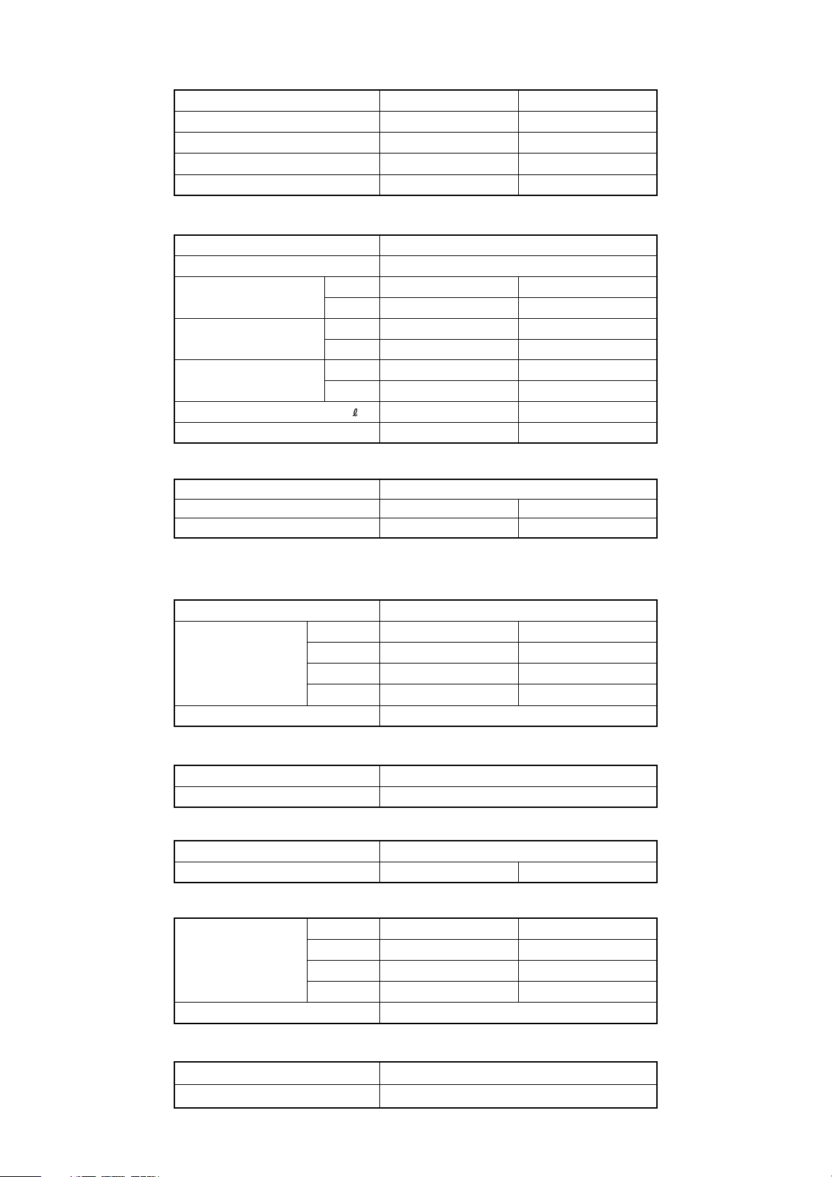
SPECIFICATIONS
TYPE
INDOOR UNIT
OUTDOOR UNIT
COOLING CAPACITY( ) : Range
HEATING CAPACITY( ) : Range
(COOL&HEAT INVERTER) (COOL&HEAT INVERTER)
ASH9LSACW ASH12LSACW
AOH9LSAC
(kW)
(kW) 3.6 (0.5~6.0) 4.8 (0.9~6.6)
2.6 (0.5~3.6) 3.5 (0.9~4.2)
AOH12LSAC
ELECTRICAL DATA
POWER SOURCE
FREQUENCY
RUNNING CURRENT
INPUT WATTS
EER
MOISTURE REMOVAL
AIR CIRCULATION-Hi
(A)
(kW)
(kW/kW)
(V) 230
(Hz)
COOLING 3.0
HEATING
COOLING
HEATING
COOLING 3.82 3.40
HEATING
( /hr)
(m3/hr)
3.6
0.68 (0.25~1.38) 1.03 (0.25~1.61)
3.96 3.61
1.3
C 630 H665
50
4.6
5.8
1.33 (0.25~2.30)0.91 (0.25~1.96)
1.8
C 630 H700
COMPRESSOR
TYPE Hermetic type,4 pole, 3 phase , DC brushles motor
DISCRIMINATION 80206680
REFRIGERANT R410A
Note : Always use a vacuum pump to purge the air.
Refrigerant for purging the air is not charged in the outdoor unit at the factory.
(g)
950
80206680
1100
FAN MOTOR
POWER SOURCE (V) 230
HI-SPEED
INDOOR UNIT
(r.p.m.)
OUTDOOR UNIT 830
MED-SPEED
LO-SPEED
QUIET
(r.p.m.)
C 1,350 H 1,420
C 1,150 H 1,200
C 950 H 1,000
C 740 H 900
DIMENSIONS
INDOOR UNIT H x W x D (mm)
OUTDOOR UNIT 535 x 780 x 250
H x W x D (mm)
280 x 790 x 230
WEIGHTS
INDOOR UNIT
OUTDOOR UNIT
GROSS / NET (kg)
GROSS / NET (kg)
12 / 9
35 / 33 37 / 34
NOISE LEVEL
HI-SPEED
(dB)
MED-SPEED
LO-SPEED
QUIET
(dB)
INDOOR UNIT
OUTDOOR UNIT
Note : Noise was measured in accordance with JIS standards, Japan.
C 42 H 42
C 37 H 36 C 39 H38
C 31 H 30 C 32 H 33
C 23 H 26 C 26 H 29
C 47 H 49
C 1,400 H 1,470
C 1,200 H 1,290
C 1,000 H 1,110
C 820 H 980
C 43 H 43
2005.02.21
MAX PIPE LENGTH
ADDITIONAL REFRIGERANT
15 m
None
1
Page 3
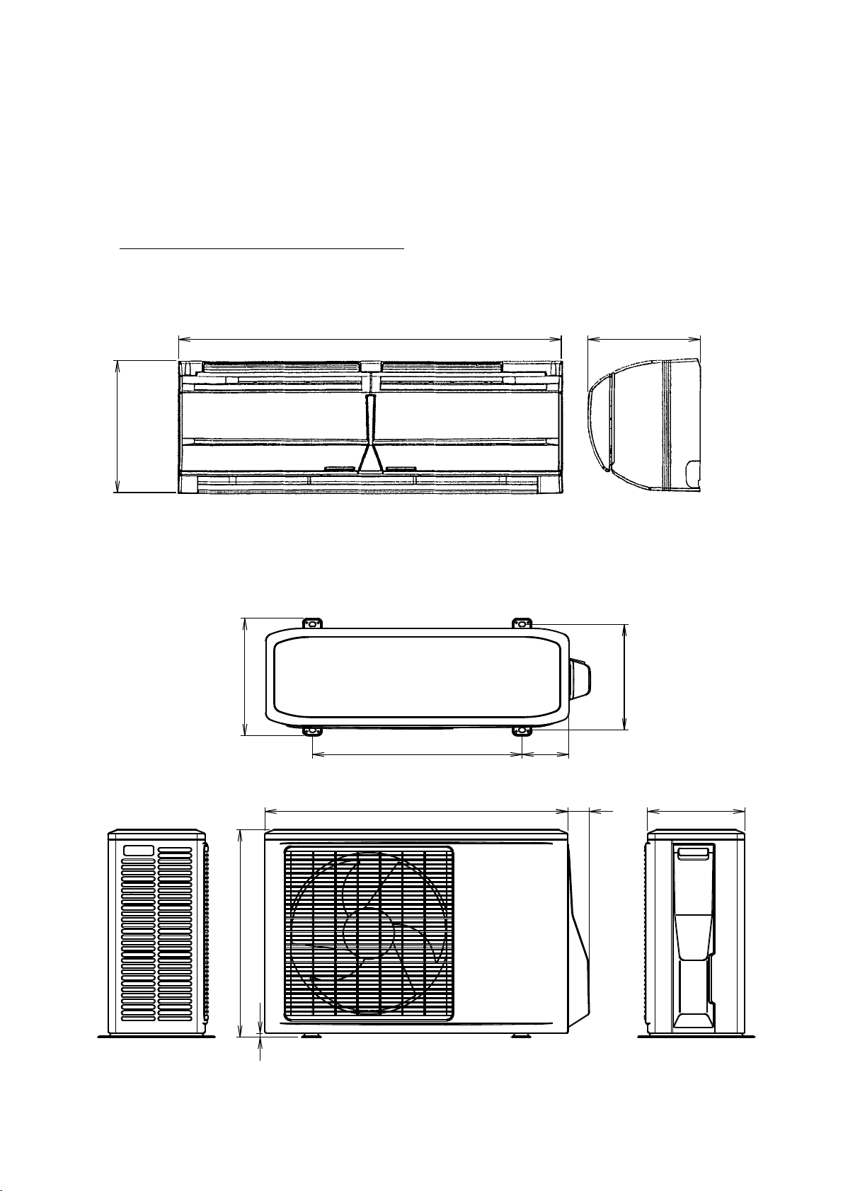
DIMENSIONS
Models : ASH9LSACW / AOH9LSAC
ASH12LSACW / AOH12LSAC
790 230
280
302
540 120
780 55
535
10
272
250
2005.02.21
2
Page 4
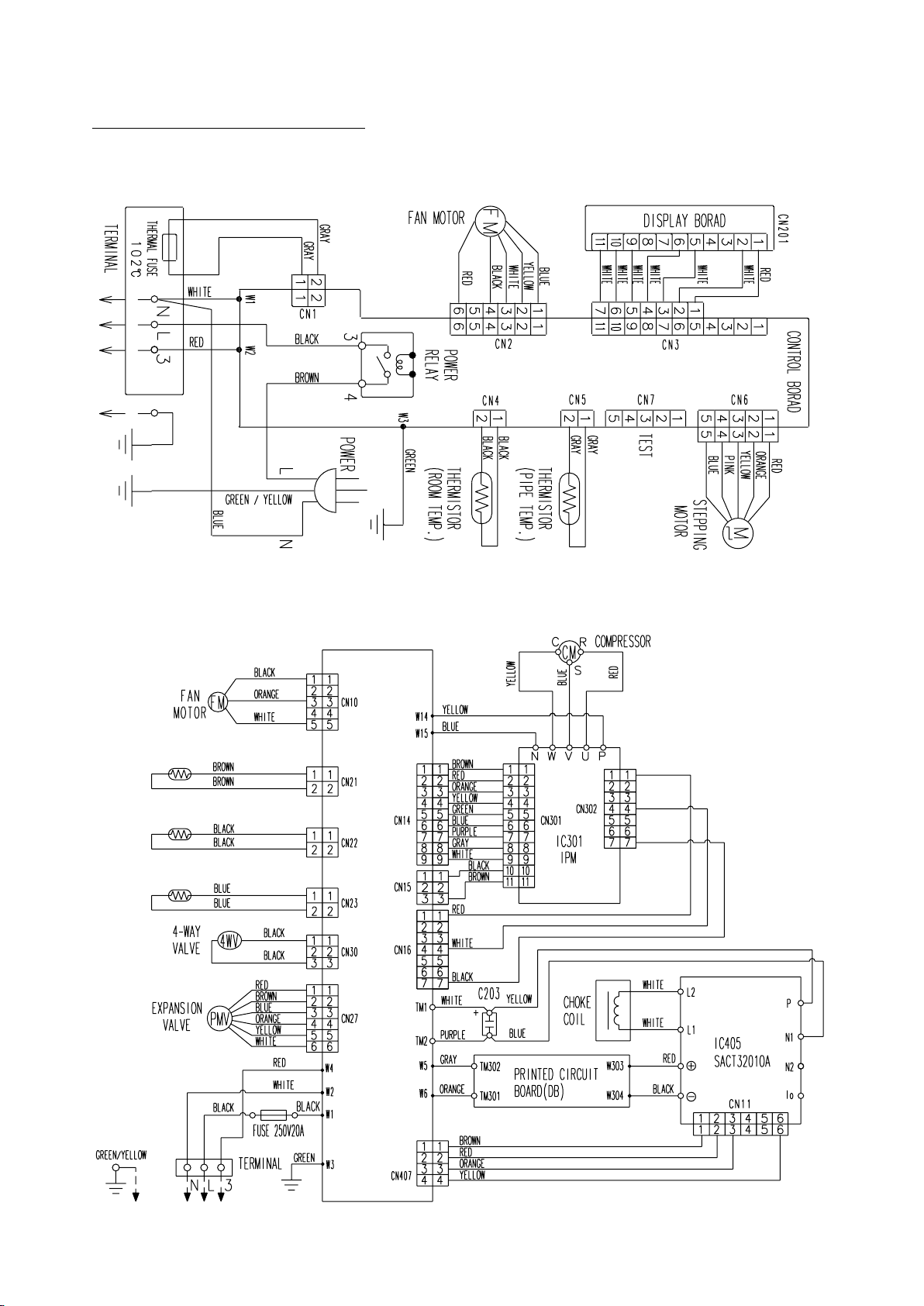
CIRCUIT DIAGRAM
Models : ASH9LSACW / AOH9LSAC
ASH12LSACW / AOH12LSAC
INDOOR UNIT
OUTDOOR UNIT
Thermistor
(discharge pipe)
Thermistor
(pipe)
Thermistor
(outdoor temp.)
Controller PCB
2005.02.21
3
Page 5
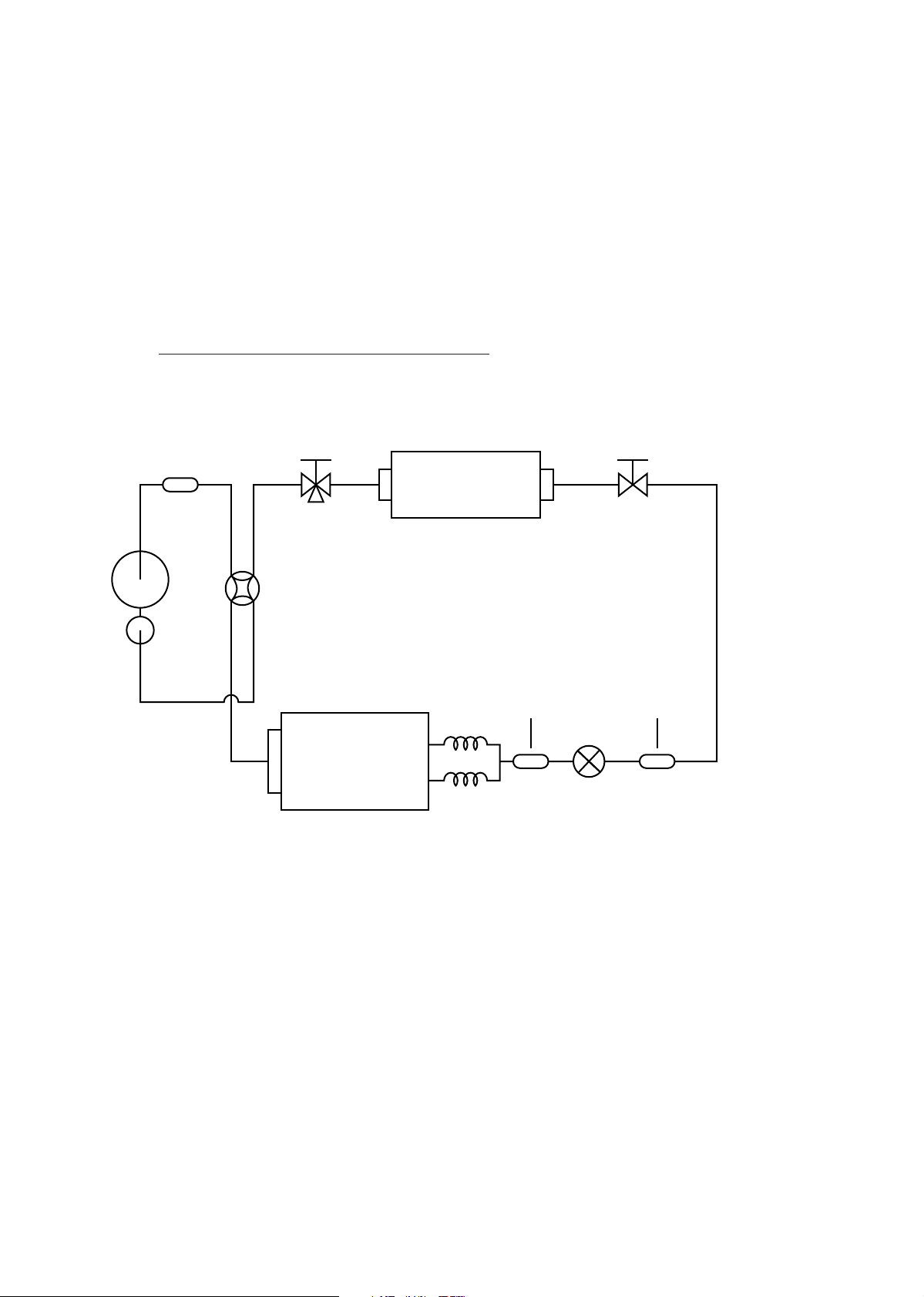
REFRIGERANT SYSTEM DIAGRAM
Models : ASH9LSACW / AOH9LSACW
ASH12LSACW / AOH12LSACW
Muffler
(2 pass)
Compressor
Accumulator
Indoor heat exchanger
4way-valve
(2 pass)
Outdoor heat exchanger
Capillary
tube
2way-valve3way-valve
Strainer Dryer
Pulse motor valve
2005.02.21
4
Page 6

ERROR CONTENTS
Self-diagnosis function table (Flashing LED Display)
Applicable model : ASH9LSACW, ASH12LSACW
* Detailed Trouble Display (secondary level) can be indicated by pressing Test Operation button.
Trouble Display (primary) Detailed Trouble Display (by Test Button)
Error
Serial signal Normal 1 sec
error blinking
Indoor unit 0.5sec 0.1sec
thermistor 2 times blinking
Operation
Timer Error
Serial reverse signal error
at operation start up
Signal reverse signal error
during operation
Serial forward signal error
at operation start up
Serial forward signal error
during operation
Indoor temperature
thermistor open
Operation
0.1sec 0.5sec
blinking 2 times
0.1sec
blinking
0.1sec
blinking
0.1sec
blinking
0.1sec 0.5sec
blinking 2 times
error
Outdoor unit 0.5sec 0.1sec
thermistor 3 times blinking
Pipe thermistor
open or short
Discharge thermistor
open or short
0.1sec 0.5sec
blinking 3 times
0.1sec 0.5sec
blinking 2 times
error
Heat exchanger
thermistor open
0.1sec 0.5sec
blinking 3 times
Timer
0.5sec
3 times
0.5 sec
4 times
0.5sec
5 times
Detailed Error Item
Normal Serial Reverse Signal can not be
received more than 10 secs
>>Releases when it becomes normal
Normal Serial Reverse Signal can not be
received more than 7 secs (after receiving
effective reverse transfer signal)
>>Releases when it becomes normal
Normal Serial Forward Signal can not be
received more than 10 secs
>>Releases when it becomes normal
Normal Serial Forward Signal can not be
received more than 10 secs ( after receiving
effective forward transfer signal)
>>Releases when it becomes normal
Thermistor detection value is open when
AC plug is inserted
IndoorIndoorIndoorIndoorIndoor OutdoorOutdoorOutdoor
>>Releases when value becomes normal
Thermistor detection value is open or short
when AC plug is inserted
>>Releases when value becomes normal
Thermistor detection value is open or short
>>Outdoor unit stops
Releases when it becomes normal
Thermistor detection value is open
Indoor unit 0.5sec 0.1sec
control error 4 times blinking
2005.02.21
Outdoor temperature
thermistor open or short
Forced automatic SW
welded
Main relay welded
Power interruption error
0.1sec 0.5sec
blinking 4 times
0.1sec 0.5sec
blinking 2 times
0.1sec 0.5sec
blinking 3 times
0.1sec 0.5sec
blinking 4 times
5
>>Outdoor unit stops
Releases when it becomes normal
Thermistor detection value is open or short
>>Outdoor unit stops
Releases when it becomes normal
Forced Auto SW is ON for more than
10 secs continuously
>>Error is indicated while it is ON
Normal Operation other than error indication
Serial Reverse Signal is received 1 min.
after Main relay becomes OFF
>>Error is indicated while serial reverse
signal is input on normal operation
Normal operation except error indication
50/60Hz is not detected after 2 secs of
power ON.
>>Error is indicated and unit is stopped
Page 7

Trouble Display (primary) Detailed Trouble Display (by Test Button)
Error
Outdoor unit 0.5sec 0.1sec
Operation
Timer Error
Current trip
Operation
Timer
0.1sec 0.5sec
control error 5 times blinking blinking 2 times
CT abnormal
0.1sec 0.5sec
blinking 3 times
0.1sec 0.5sec
blinking 5 times
0.1sec 0.5sec
Indoor fan 0.5sec 0.1sec
Compressor rotation
error
Abnormal lock
motor error 6 times blinking blinking 2 times
Abnormal rotation
0.1sec 0.5sec
blinking 3 times
Refrigerant 0.5sec 0.1sec
cycle error 7 times blinking blinking 2 times
Optional 0.5sec 0.1sec
function 8 times blinking blinking 2 times
Discharge temperature
abnormal
Cooling high pressure
abnormal rise
Active filter voltage
abnormal (3rd time)
0.1sec 0.5sec
0.1sec 0.5sec
blinking 3 times
0.1sec 0.5sec
error
Active filter voltage
abnormal (1st time)
0.1sec 0.5sec
blinking
3 times
Detailed Error Item
Current trip error is 2nd time within
start up
>>Permanent stop
Current detection value is 0A for more
than 1 sec when compressor is operated
at more than 90rps
>>Outdoor unit is stopped until power
supply to Outdoor unit is stopped
Compressor location detection error (incl.
failed start up) for 3 times
>>Permanent stop
Detected rotation is 0 r.p.m. at start up or
at 56 secs after Fan mode is selected
IndoorIndoor OutdoorOutdoorOutdoorOutdoorOutdoorOutdoorOutdoor
>>Permanent stop
Detected rotation is 1/3 of target r.p.m. at
start up or at 56 secs after Fan mode is
selected
>>Permanent stop
Discharge Temperature protection
(Discharge temperature is 110degC)
operated 2 times
>>Permanent stop
High pressure rise protection (Outdoor
heat exchanger temperature is 65degC)
operated
>>Comp. OFF (releases after 3min.ST)
Error is indicated while 3 min.ST
Active Filter voltage error operated 3 times
>>Permanent stop
Active Filter Module error or open
detection protection operated
2005.02.18
>>Automatic release after 3 min. ST
6
Page 8

INDOOR PCB CIRCUIT DIAGRAM
TERMINAL BOARD
RED
GREEN
GREEN
BLUE
GREEN / YELLOW
WHITE
BLACK
BROWN
POWER SOURCE
220 / 240V
50Hz
CONTROLLER PCB ASEMBLY (MAIN PCB)
ASH9LSACW : EZ-00219HSE-C
ASH12LSACW : EZ-0021CHSE-C
THERMAL FUSE
I C 1
uPD780024SGB-X09
GRAY
GRAY
ROOM TEMPERATURE THERMISTOR
BLACK
BLACK
PIPE TEMPERATURE THERMISTOR
GRAY
GRAY
FAN MOTOR
RED
BLACK
WHITE
YELLOW
BLUE
REMOTE CONTROL
CUSTOM CODE
AUTO RESTART
RED
WHITE
WHITE
WHITE
WHITE
WHITE
WHITE
RED
ORANGE
YELLOW
PINK
BLUE
INDICATOR PCB
EZ-00219HSE-D (F)
LOUVER
2005.02.21
7
Page 9

POWER SOURCE
220 - 240V
50Hz
CONTROLLER PCB ASSEMBLY ( MAIN PCB)
AOH9LSAC : EZ-002LHUE-C
AOH12LSAC : EZ-002GHUE-C
SC-10-55JH
N200500K
OUTDOOR PCB CIRCUIT DIAGRAM
2005.02.21
MB90462-117
AOY9LSAC
AOY12LSAC
8
Page 10

Models :
ASH9LSACW
ASH12LSACW
DISASSEMBLY ILLUSTRATION
2005.02.21
9
Page 11

Models :
ASH9LSACW
ASH12LSACW
2005.02.21
10
Page 12

Models :
AOH9LSACW
AOH12LSACW
2005.02.21
11
Page 13

INDOOR UNIT
PARTS LIST
Ref.
Description
No.
1 Air Filter-L
2
Air Filter-R
4 Guide (Filter)-L
Guide (Filter)-R
5 9311254010
6 9311025023
Grille (Top)-L
7
Grille (Top)-R
8 9311903048
Front Panel Assy
9 9311784043
Emblem-A
10 Emblem-B 9311785026
11 Bearing (Panel)-L 9311029014
12 Bearing (Panel)-R
13 Grille (Intake)-L
Grille (Intake)-R
14 9311783039
15 Shaft (Grille)-L
Shaft (Grille)-R
16 9311149019
Gear-A
20 9309994003
21 Casing Assy 9312112036
23 Cover (Casing)-B 9311916017
24 Cross Flow Fan Assy 9307836015
25 Motor Cushion-B 9306274009
26 Clamper (Motor) 9310102008
27 Shaft Holder-C Assy 9306628017
28 Drain Hose Assy
Drain Cap Assy
29 9304150008
Wire Clamper
30 9311946014
31 Box (Switch) 9309996014
32 Cover (Switch) 9311863014
33 Evaporator Total Assy 9311495017
36 Joint Pipe Assy-E 9311497011
37 9304607007
Insulation(Pipe)-E
ASH9LSACW ASH12LSACW
9311027010
9311028017
9311180012
9311026020
9311030010
9311782049
9305435012
9310357019
Part No.
Ord.
Q'ty
9311027010
9311028017
9311180012
9311254010
9311025023
9311026020
9311903048
9311784043
9311785026
9311029014
9311030010
9311782049
9311783039
9305435012
9311149019
9309994003
9312112036
9311916017
9307836015
9306274009
9310102008
9306628017
9310357019
9304150008
9311946014
9309996014
9311863014
9311495017
9311497011
9304607007
2005.02.21
38 Holder (Evaporator)-L
39 9309983014
Holder (Evaporator)-R
Water Seal
40
Air Seal
42
Terminal
43
Step Motor
46
Fan Motor Assy
48
51 9312058013
Remote Control Unit
52 Bracket Panel 9310001004
61-1 Flow Control Panel-U 9330009011
61-2 9309992023
Flow Control Panel-Z
188 Power Cord 9900001025 9900070038
236 Controller PCB Assy 9705001053
--- Pipe Thermister 9702039011 9702039011
--- Room Thermister 9700801108 9700801108
--- Indicator PCB 9704838032 9704838032
When you order parts, please make a photocopy of this page
and fill the number of the parts in the "Order" column.
9309982017
9310721001
9310611005
9701955077
9900139025
9601351016
9309982017
9309983014
9310721001
9310611005
9701955077
9900139025
9601351016
9312058013
9310001004
9330009011
9309992023
9705001060
12
Page 14

OUTDOOR UNIT
Ref.
No.
1
Blow Grill
3
Grip 9302061016
5
Cabinet Front Panel, Painted
7
Electric Cover 9310979013
9
Cabinet Rear Panel, Painted
10
12
14
16
17
23 Inverter PCB Assy 9705092020 9705092013
24 Thermistor (Discharge) 9704219060 9704219060
28 Solenoid Coil 9970033018 9970033018
29 Coil (Expansion Valve) 9900057015 9900057015
39 Propeller Fan 9309909014 9309909014
39-1 Inverter Cover 9311017011 9311017011
40 Inverter Base 9311015017 9311015017
41 Fan Motor Assy 9601474012 9601474012
42 Bracket (Motor) 9306047023 9306047030
46 Compressor Assy 9312448012 9312448012
Pulse Motor Valve 9900056018 9900056018
Base Assy, Painted
2-Way Valve Assy 9310084014 9310084014
Condenser Sub Assy
3-Way Valve Assy 9311487012 9311487012
Description
AOH9LSAC AOH12LSAC
9309929012 9309929012
9309928053 9309928053
9309870024
9310248027
9312586028
Part No.
9302061016
9310979013
9309870024
9310248027
9312586011
Ord.
Q'ty
84 Thermistor (Condenser) 9704220011 9704220011
98 Fan Ring 9309876026 9309876026
138 Separate Wall 9311013013 9311013013
344 4-Way Valve 9900047016 9900047016
527 Protective Net 9310980019 9310980019
734 Panel Top, Painted 9310338063 9310338063
--- Emblem 9312635016 9312635016
---
---
---
--- Controller PCB 9705093218 9705093201
--- ACTPM PCB 9703457012 9703457012
--- TR PCB Assy 9705553019 9705553019
--- Diobe Bridge PCB 9705094017 9705094017
---
---
Inverter capacitor 9704594013 9704594013
Fan capacitor 9900042011 9900042011
Outdoor Thermister 9703516061 9703516061
(EZ-002LHUE-C) (EZ-002GHUE-C)
(K04AK-0400HUE-TRO)
(EZ-002GHUE-DB) (EZ-002GHUE-DB)
Noise Filter beside compressor 0400056119 0400056119
Noise Filter beside diobe bridge PCB
When you order parts, please make a photocopy of this page
and fill the number of the parts in the "Order" column.
0400056133 0400056133
2005.02.21
13
Page 15

STANDARD ACCESSORIES
Part No.
Name and Shape
Wall hook bracket
Remote control
unit
Battery (penlight)
Cloth tape
ASH9LSACW
ASH12LSACW
9312752010
9312058013
0600185534
9310519004
Tapping screw
( 4 x 25 )
0700076046
2005.02.21
14
Page 16

0304G2230
 Loading...