

Page 1
Models Indoor unit Outdoor unit
ARG9ALB
ARG9RLB
AOG9AGA
AOG9RGA
CONTENTS
SPECIFICATIONS . . . . . . . . . . . . . . . . . . . . . . . . . . . . . . . . .1
OUTLINE AND DIMENSIONS . . . . . . . . . . . . . . . . . . . . . . . . 2
CIRCUIT DIAGRAM . . . . . . . . . . . . . . . . . . . . . . . . . . . . . . . .3
INDOOR PRINTED CIRCUIT BOARD CIRCUIT DIAGRAM . . . .5
OUTDOOR PRINTED CIRCUIT BOARD CIRCUIT DIAGRAM . .7
PRINTED CIRCUIT BOARD LAYOUTS . . . . . . . . . . . . . . . . . . 8
REFRIGERANT SYSTEM DIAGRAM . . . . . . . . . . . . . . . . . . .10
DISASSEMBLY ILLUSTRATION. . . . . . . . . . . . . . . . . . . . . . .11
PARTS LIST . . . . . . . . . . . . . . . . . . . . . . . . . . . . . . . . . . . . .21
Page 2
– 1 –
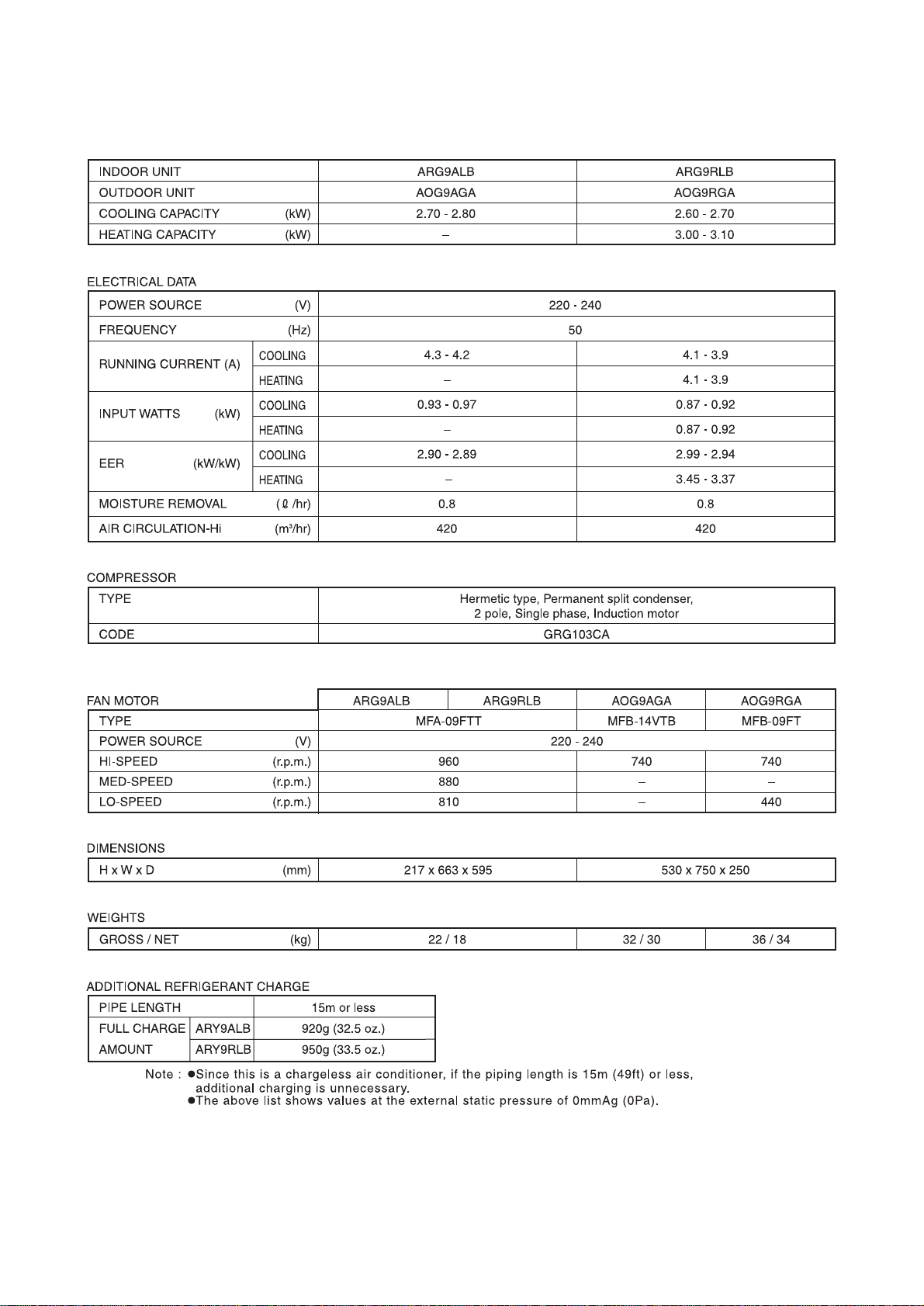
SPECIFICATIONS
Page 3

– 2 –
INDOOR UNIT
OUTDOOR UNIT
540
750
250
285
530
13
596
560
663
630
400
390
150
217
605
57520
OUTLINE AND DIMENSIONS
(Unit : mm)
INDOOR UNIT
OUTDOOR UNIT
Page 4

– 10 –
REFRIGERANT SYSTEM DIAGRAM
Models : ARG9RLB/AOG9RGA
Models : ARG9ALB/AOG9AGA
Page 5
– 3 –
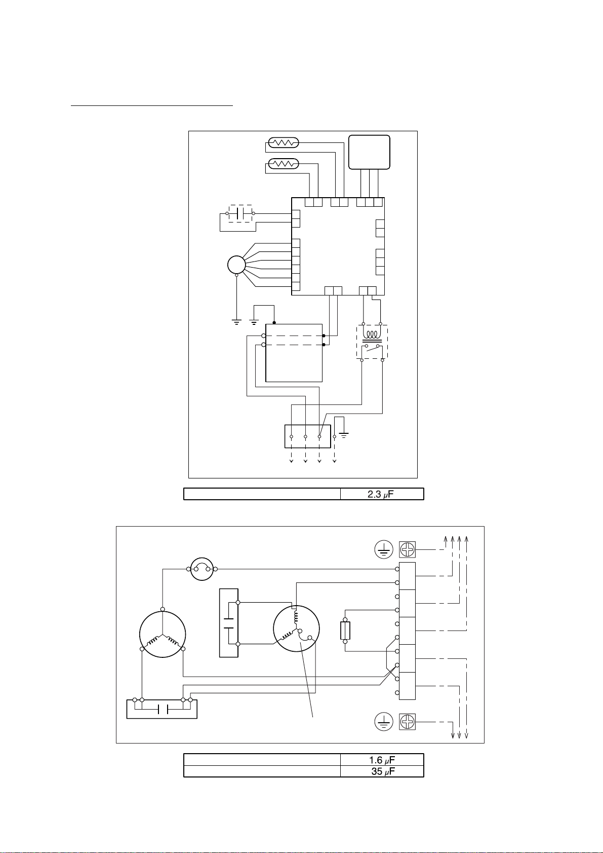
FAN MOTOR CAPACITOR
COMPRESSOR CAPACITOR
FAN MOTOR CAPACITOR
THERMISTOR
(PIPE TEMP.)
THERMISTOR
(ROOM TEMP.)
FAN
MOTOR
FAN
MOTOR
OVERLORD
PROTECTOR
COMPRESSOR
TO INDOOR UNITTO POWER SUPPLY
COMPRESSOR
CAPACITOR
THERMAL
PROTECTOR
TERMINAL
FAN MOTOR
CAPACITOR
FAN MOTOR
CAPACITOR
MAIN
RELAY
REMOTE
CONTROL
UNIT
CONTROL
BOARD
FILTER
BOARD
GRAY
WHITE
WHITE
WHITE
BLACK
BLACK
BLACK
BLACK
RED
RED
ORANGE
WHITE
WHITE
WHITE
WHITE
WHITE
BLUE
GREEN
BLUE
PURPLE
PINK
RED
GRAY
BLACK
BLACK
BLACK
RED
RED
RED
WHITE
BLACK
BLACK
BLACK
WHITE
BLACK
WHITE
GREEN/YELLOW
CN17CN8
INDOOR UNIT
OUTDOOR UNIT
1212
CN7
CN4
CN6CN15
CN5
CN1
1
1
1
2
3
1
2
3
4
5
6
2
1
2
2
12
CN12
12
3
FM
1
2
(N)
3
N
L
TERMINAL
TO OUTDOOR UNIT
1
N
L
2
(N)
3
Use T3. 15A-250V
Fuse on F101
SR
C
5A
FUSE
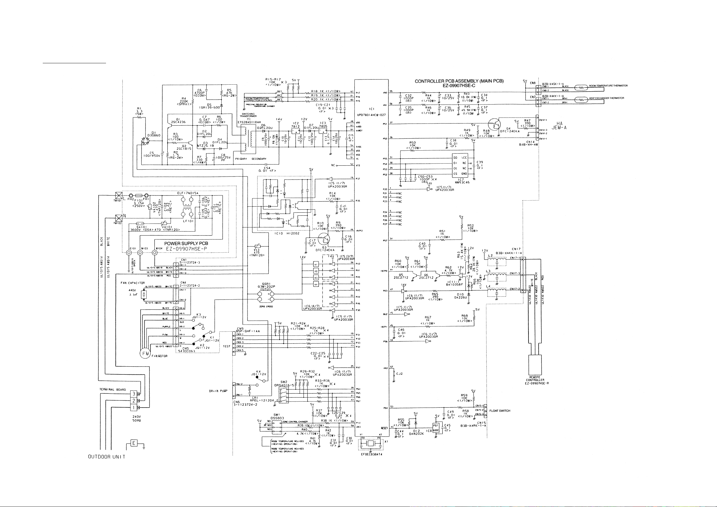
CIRCUIT DIAGRAM
Models : ARG9ALB/AOG9AGA
Page 6

– 4 –
COMPRESSOR CAPACITOR
FAN MOTOR CAPACITOR
FAN MOTOR CAPACITOR
THERMISTOR
(PIPE TEMP.)
THERMISTOR
(ROOM TEMP.)
THERMISTOR
(OUTDOOR TEMP.)
FAN
MOTOR
FAN
MOTOR
PRINTED CIRCUIT BOARD
TEST
TRANSFORMER
TO INDOOR UNITTO POWER SUPPLY
FAN MOTOR
CAPACITOR
COMPRESSOR
TERMINAL
POWER RELAY
COMPRESSOR
CAPACITOR
SOLENOID
COIL
FAN MOTOR
CAPACITOR
REMOTE
CONTROL
UNIT
CONTROL
BOARD
FILTER
BOARD
GRAY
GREEN
BLACK
BLACK
BLACK
WHITE
WHITE
WHITE
RED
BLACK WHITE
WHITE WHITE
BLUE
RED
RED
RED
PURPLE
PURPLE
BLUE
WHITE
BLACK
ORANGE
RED
OVERLOAD
PROTECTOR
RED
WHITE
WHITE
WHITE
BLACK
BLACK
BLACK
BLACK
GREEN
BLUE
PURPLE
PINK
RED
GRAY
BLACK
BLACK
BLACK
RED
WHITE
BLACK
WHITE
RED
BLACK
WHITE
GREEN/YELLOW
CN17CN8
CN13CN12CN11
CN2CN3CN4CN1CN9CN15 CN5
CN10
INDOOR UNIT
OUTDOOR UNIT
1212
CN7
CN4
CN6CN15
CN5
CN1
1
1
1
2
3
1
2
3
4
5
6
2
1
2
2
134
13NL
2
(N)
312 12 12 1212 1
12
THERMISTOR
(PIPE TEMP.)
GRAY
GRAY
12123
THERMISTOR
(DISCHARGE TEMP.)
BROWN
BROWN
12
57
123
3
FM
SV
TERMINAL
TO OUTDOOR UNIT
1
N
L
2
(N)
3
Use T3. 15A-250V
Fuse on F101
R
S
C
NO
COM
Models : ARG9RLB/AOG9RGA
Page 7
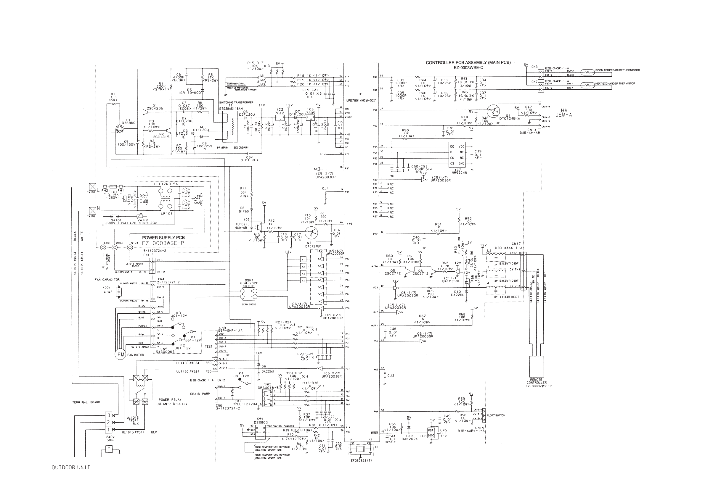
Model : ARG9ALB
INDOOR PRINTED CIRCUIT BOARD
CIRCUIT DIAGRAM
– 5 –
Page 8
Model : ARG9RLB
– 6 –
Page 9

Model : AOG9RGA
OUTDOOR PRINTED CIRCUIT BOARD
CIRCUIT DIAGRAM
– 7 –
Page 10

– 8 –
PRINTED CIRCUIT BOARD LAYOUTS
CONTROLLER PCB ASSEMBLY
(Viewed from the solder side)
FILTER PCB ASSEMBLY
(Viewed from the solder side)
INDOOR UNIT
Page 11

– 9 –
CONTROLLER PCB ASSEMBLY
(Viewed from the solder side)
(Viewed from the component side)
OUTDOOR UNIT
Page 12

– 11 –
16
39
9
745
2
373
5
734
527
4
7
98
138
42
12
423
41
Model : AOY9AGA
DISASSEMBLY ILLUSTRATION
Model : AOG9AGA
Page 13

– 12 –
Model : AOG9AGA
Page 14

– 13 –
Model : AOG9AGA
Page 15

– 14 –
213
16
304
549
678
39
9
745
2
373
5
734
527
4
7
98
744
138
42
12
764
764
765
766
423
41
Model : AOY9RGA
Model : AOG9RGA
Page 16

– 15 –
Model : AOG9RGA
Page 17

– 16 –
Model : AOG9RGA
Page 18

– 17 –
Models : ARG9ALB,ARG9RLB
Page 19

– 18 –
Models : ARG9ALB,ARG9RLB
Page 20

– 19 –
Model : ARG9ALB
Page 21

– 20 –
Model : ARG9RLB
Page 22

– 21 –
Ref. No. Description
34
56
63
67
74
109
126
138
143-1
146
147
160
164
174
184-1
196-2
210
211
232
234
235
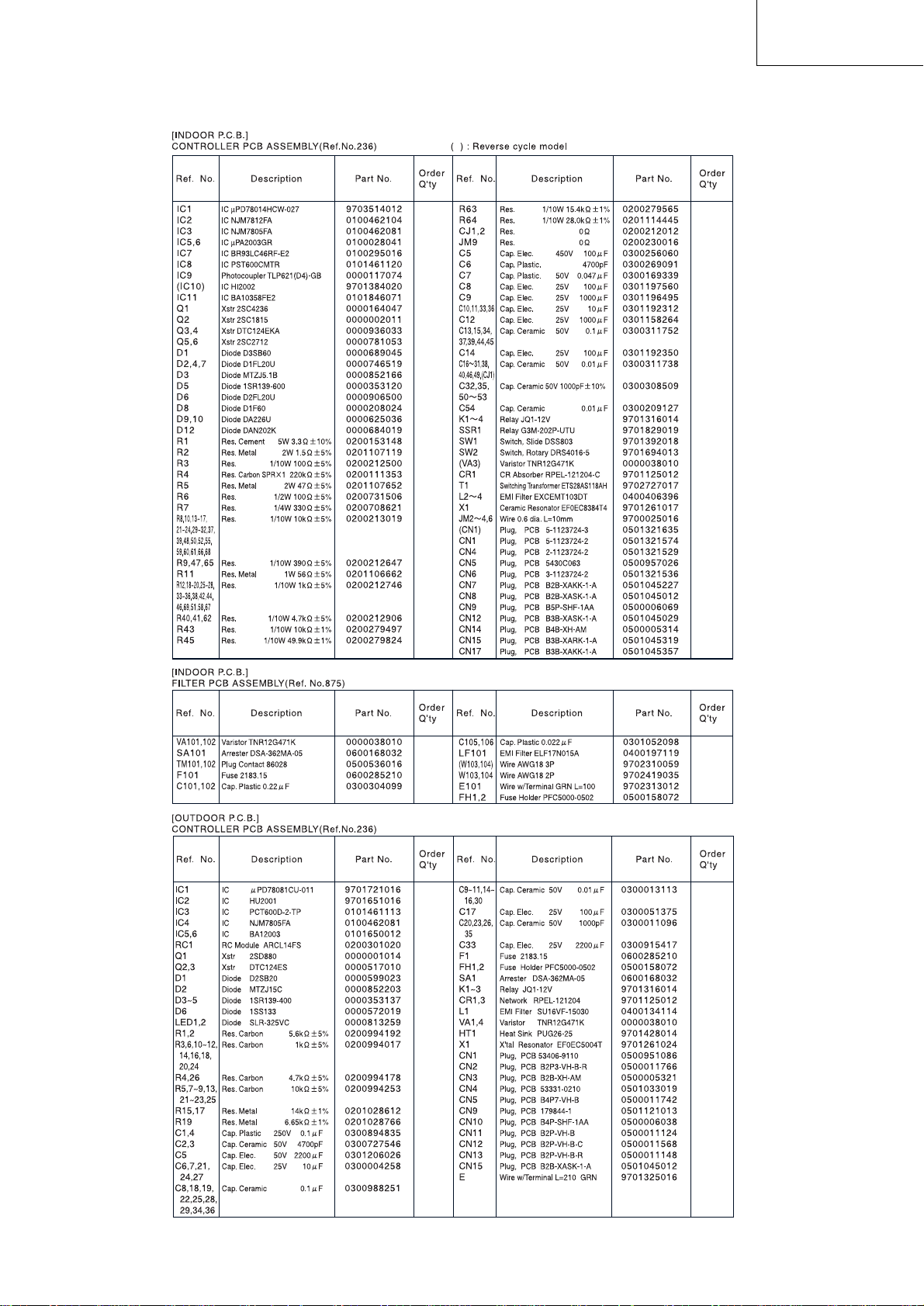
236
Capacitor (Fan Motor)
Sirocco Fan Assy
Panel Assy Front
Rubber (Vibration-proof)
Filter
Casing Assy
Motor Fixing Table Assy
Separate Wall
Clamp NK-3N
Evaporator Assy
Inlet Pipe (Eva.) Assy
Drain Pan
Fan Motor Assy
Hanger Bracket L
Thermo. Spring-A
Clamp SKB-150
Main Relay
Cushion Rubber
Outlet Pipe (Eva.) Assy
Thermistor Assy-Room
Thermistor Assy-Pipe
Controller PCB Assy
9357965017
9358621004
9363722000
313659068604
9363326000
9363322002
9358591000
9363193008
313361274700
9364456027
9363373004
9363324006
9600778074
9363195002
313728262708
313035356905
9356781007
313806328306
9363387001
9703299063
9703297052
9703582035
9357965017
9358621004
9363722000
313659068604
9363326000
9363322002
9358591000
9363193008
313361274700
9364456027
9363373004
9363324006
9600778074
9363195002
313728262708
313035356905
—
—
9363387001
9703299063
9703297052
9703582028
Order
Q’ty
Part No.
ARG9ALB ARG9RLB ARG9ALB ARG9RLB
Ref. No. Description
240
244
287
320-1
338
380
381-4
455
464
514
567
588-1
588-2
625
653-1
689
734
762
761
815-1
875
982-1
982-2
Remote Control Unit
Cover (Piping)
Cap (Power)
Wire Clamp Metal
Motor Fixture
Locking Spacer
Locking Spacer
Control Box
Cover (Cabinet)
Control Box Cover
Support Plate (Eva.)
Bracket Eva.R
Bracket Eva.L
Cord Bushing
Bolt (Fan Motor Fixing)
Screw, Grip Tapping
Panel T op
Panel Side Assy (L)
Panel Side Assy (R)
Terminal-3P
Filter PCB Assy
Cord Clamp
Cord Clamp-B
9701673056
9363330007
9352173011
313483219905
9358594001
313209391403
0600118075
9363200003
9363325003
9363201000
9363323009
9363199000
9363198003
9359240006
0700156014
9357837000
9363408003
9363409000
9363411003
9356488005
9703611018
9356857009
9356858006
9701673049
9363330007
9352173011
313483219905
9358594001
313209391403
0600118075
9363200003
9363325003
9363201000
9363323009
9363199000
9363198003
9359240006
0700156014
—
9363408003
9363409000
9363411003
9356488005
9703583018
9356857009
9356858006
Order
Q’ty
Part No.
Ref. No. Description
2
4
5
7
9
12
13
14
15
16
18
19
20
32-1
32-2
34
37
38
39
41
42
47-1
51
55
98
105
107
109
128-1
138
178-2
184-1
199-1
200-1
200-2
Fan Cover
Emblem-Rear
Cabinet-A, Painted
Connector Cover
Cabinet-B, Painted
Base Assy, Painted
3-Way Valve
2-Way Valve
Dryer
Condenser Assy
Suction Pipe
Capillary Tube
Discharge Pipe Assy
Control Box Metal-A
Control Box Metal-B
Capacitor (Fan Motor)
Running Capacitor
Capacitor Clamp
Propeller Fan Assy
Fan Motor Assy-Out
Bracket (Motor)
Rubber (Discha.Pipe)
Special Nut
Special Nut M8 (For Comp.)
Fan Ring
Compressor Assy
Rubber Seat-A (For Comp.)
Terminal Cover (For Comp.)
Rubber (Discharge Pipe)
Separate Wall
Capillary Holder Rubber
Thermo. Spring-A
BR Sheet
BR Sheet-B
BR Sheer-B
9304109006
313698088313
9302936017
9357970004
9302935010
9354493032
9356494006
9364615004
—
9354494015
9364486000
9365091005
9364484006
9363406009
—
9700468080
9356386066
313468061808
9351589011
9600649060
313166243804
313194159807
9359430018
9355091008
313166296109
9364555003
9359425014
9363263008
313155086308
9300672016
—
—
313612108209
—
9351990039
9304109006
313698088313
9302936017
9357970004
9303744017
9354493032
9356494006
9364615004
313523082505
9364547008
9363474008
9364538006
9363406009
9363407006
9700468080
9356386066
313468061808
9351589011
9600649107
313166243804
—
9359430018
9355091008
313166296109
9364555003
9359425014
9363263008
313155086308
9303729014
313394274808
313728262708
313612108209
9351990022
9351990039
Order
Q’ty
Part No.
AOG9AGA AOG9RGA AOG9AGA AOG9RGA
Ref. No. Description
210
213
230
233
236
272
304
329
334
343
344
373
381
412
420
423
456
527
549
552
582
628
635
678
734
744
745
764
765
766
788
815
823-2
824-4
982-1
982-2
Main Relay
Noise Insulation-B
Overload Relay
Power Transformer
Controller PCB Assy
Strainer
Thermostat Fixture-B
Joint Pipe Assy
Suction Pipe-B
Solenoid Coil
4-Way Valve
Grip
Locking Spacer
Terminal Gasket
Capillary Assy
Noise Insulation-F
Pipe-A
Protection Net
Thermostat Assy-Outer
Thermistor Assy
Discharge Pipe-F
Locking Spacer-B
Terminal Washer
Bracket (Thermistor)
Cabinet T op Plate
Clamp (Condenser)
Motor Support
Drain Cap
Drain Pipe (L-Type)
Drain Pipe Packing
Thermistor-Discharge
Terminal-5P
Fuse Holder
Fuse
Cord Clamp
Cord Clamp-C
—
—
9359927013
—
—
9357309002
—
—
—
—
—
313166178700
—
9362004008
—
9350944019
9352267017
9355434003
—
—
9301425017
—
9359428015
—
9302937014
—
313166036308
—
—
—
—
9356497021
0500063024
0600222529
9356857009
9359677000
9356781007
313584258005
9359927013
9701549016
9703572012
—
313349051500
9364458007
9351186012
9359616122
313947302811
313166178700
313209391506
9362004008
9363412000
9350944019
—
9355444002
9357328027
9701330034
—
313005446558
9359428015
313557406106
9302937014
313166374106
313166036308
313166024302
9301102000
9301143003
9358337011
9356497021
—
—
9356857009
9359677000
Order
Q’ty
Part No.
—
INDOOR UNIT
OUTDOOR UNIT
When you order parts, please make a photocopy of this page
and fill the number of the parts in the "Order" column.
ARG9ALB/AOG9AGA
ARG9RLB/AOG9RGA
PARTS LIST
Page 23
– 22 –
When you order parts, please make a photocopy of this page
and fill the number of the parts in the "Order" column.
ARG9ALB/AOG9AGA
ARG9RLB/AOG9RGA
Page 24

– 23 –
INDOOR UNIT ACCESSORIES
Name and Shape Q’ ty Application ARG9ALB ARG9RLB
Name and Shape Q’ ty Application AOG9AGA AOG9RGA
OUTDOOR UNIT ACCESSORIES
For vacuum
Installation
template
Hook metal
Tapping screw
(
fl4 x 10)
Special nut A
(large flange)
Special nut B
(small flange)
Coupler heat
insulation
(large)
Coupler heat
insulation
(small)
Binder
Remote
control unit
Remote control unit
cord clamp
Tapping screw
(flush heads)
Filter
Drain hose
insulation
Hexagon
wrench
Cap (drain)
1
4
8
4
4
1
1
(Small)
1
1
10
10
2
1
1
1
1
2
For positioning the indoor
unit
For suspending the indoor
unit from ceiling
For suspending the indoor
unit from ceiling
For installing the hanger
For indoor side pipe joint
(large pipe)
For indoor side pipe joint
(small pipe)
For remote control unit and
remote control unit cord
binding
For installing the remote
control unit cord
For installing the remote
control unit cord clamp
Insulates the drain hose
and vinyl hose connection
For outdoor unit drain
piping work (May not be supplied,
depending on the model)
9351228019
9301143003
9301102000
313166024302
9351228019
93642240089364224008
93631950029363195002
3113005446653313005446653
301171164104301171164104
313005446759313005446759
93507160299350716029
93527660159352766015
313361275805313361275805
(Large)
4
For fixing the coupler heat
insulation
312300787605312300787605
97016730499701673056
313714181904313714181904
301141153027301141153027
93633260009363326000
313806217708313806217708
Drain pipe packing
Drain pipe
STANDARD ACCESORIES
Page 25

October 2000 Printed in Japan0010K1758
 Loading...