

Page 1
R22
4 . DUCT TYPE AR 36ALD3 , AR 45ALC3
D2D_AR013E/01
2005.09.15
Page 2
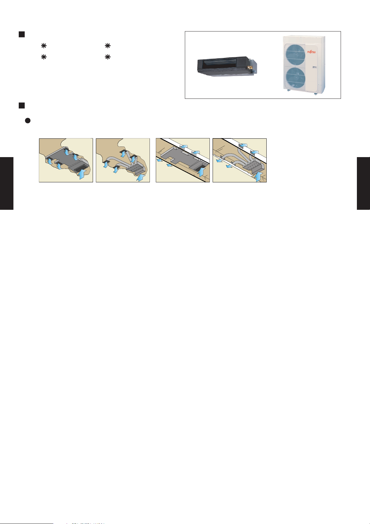
4-1. FEATURE
MODELS :
AR 36ALD3 / AO 36APA3L
AR 45ALC3 / AO 45APA3L
FEATURES
Installation styles
Embedded in Ceiling
Hanging from Ceiling
DUCT TYPE
DUCT TYPE
AR36 - 45
AR36 - 45
- (04 - 01) -
Page 3
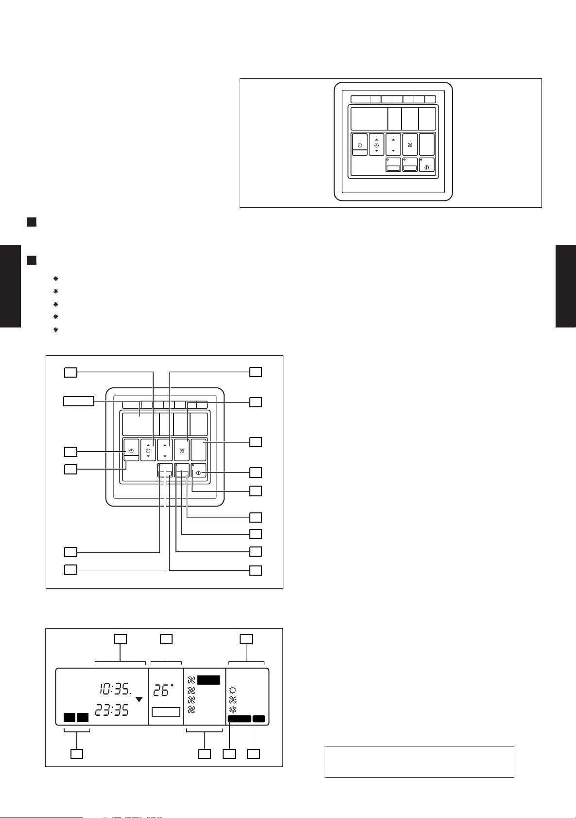
4-2. REMOTE CONTROLLER
4-2-1. WIRE REMOTE CONTROLLER WITH WEEKLY TIMER
REMOTE CONTROLLER WITH WEEKLY TIMER
1
DAY CODE
MON2TUE3WED4THU5FRI6SAT
TEMP./DAY
SET TIME
TIMER
MODE
CLOCK ADJUST
FEATURES
Three kinds of timer setup (OFF/ON/WEEKLY) are possible.
Function of weekly timer
Setting of different on-off time by day
Setting of set on-off time twice a day
Setting of time in 5 minute steps
DUCT TYPE
AR36 - 45
Timer operation of a reserved day can be temporarily cancelled by pushing the “DAY OFF” button.
Time setting can be left until the next day.
1 START/STOP Button
Pressed to start and stop operation.
11
12
2 OPERATION Lamp
Lights during operation and when the timer is on.
3 DAY OFF Button
Display
REMOTE CONTROLLER WITH WEEKLY TIMER
1
DAY CODE
MON2TUE3WED4THU5FRI6SAT
13
Temporary cancellation of one day timer
4 ENERGY SAVE Button
Turns energy save mode on and off.
5 ENERGY SAVE Button
Lights when the unit is in the energy save mode.
6 SET Button
Sets the date, hour, minute and on-off time.
10
TIMER
MODE
CLOCK ADJUST
9
FAN
CONTROL
MASTER
CONTROL
ZONE
ENERGY SAVE
DAY OFF
START/STOP
SET
14
1
TEMP./DAY
SET TIME
7 ZONE Button
2
Use to turn zone control on and off.
8 ZONE Lamp
3
4
8
7
5
6
Lights when the unit is in the zone control mode.
9 CLOCK ADJUST Button
10 TIMER MODE Button
Changes the timer mode (NON STOP, OFF TIMER,
ON TIMER, WEEKLY TIMER).
11 SET TIME Button
Sets the current time and on-off time.
12 TEMP./DAY Button
Sets the indoor temperature / day.
#
Display panel
1615
17
13 FAN CONTROL Button
14 MASTER CONTROL Button
Selects the operating mode
(HEAT, FAN, COOL).
15 Clock Display
NON STOP
OFFON
TIMER
WEEKLY
2
1
CLOCK
TIMER
NEXT DAY
OFF
ON
ON
OFF
TEMP.
DAY
DAY OFF
AUTO
C
HIGH
MED
LOW
HEAT
FAN
COOL
DEFROST TEST
16 Set Temperature / Day Display (TEMP./DAY)
17 Operation Mode Display
18 Timer Mode Display
#
19 Fan Speed Display
20 DEFROST Display
21 TEST Display
FAN
CONTROL
MASTER
CONTROL
ENERGY SAVE
ZONE
SET
DAY OFF
START/STOP
DUCT TYPE
AR36 - 45
18
2019
21
#NOTE :
This model does not have a fan speed function.
- (04 - 02) -
Page 4
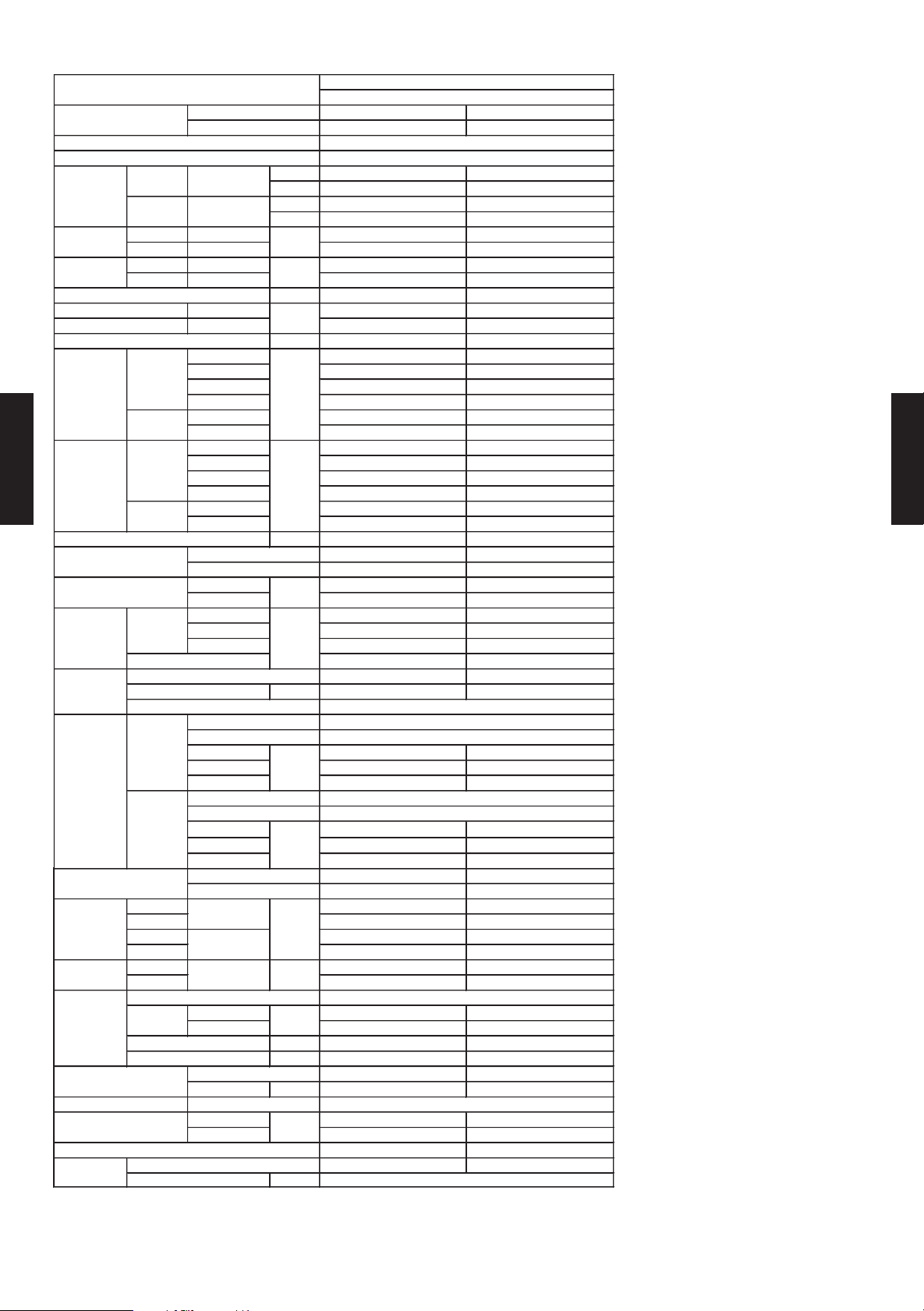
4-3. SPECIFICATIONS
AR*36ALD3 AR*45ALC3
AO*36APA3L AO*45APA3L
kW 10.3 - 10.5 12.4 - 12.7
BTU/h 35100 - 35800 42300 - 43300
kW - -
BTU/h - -
COOLING RATED 3.90 - 4.00 4.45 - 4.57
HEATING RATED - -
COOLING RATED 6.6 - 6.6 7.5 - 7.5
HEATING RATED - -
A 50 55
EER COOLING 2.64 - 2.63 2.97 - 2.78
COP HEATING - -
l/h (pints/h) 3.1 (6.55) 6.0 (12.7)
High 1800 / - 1850 / -
Med 1700 / - 1750 / -
Low 1600 / - 1650 / -
Quiet - -
High 6000 / - 5900 / -
Low - -
High 1280 / - 1320 / -
Med 1200 / - 1270 / -
Low 1130 / - 1200 / -
Quiet 970 / - 1090 / -
High 770 / - 790 / -
Low - 510 / -
Pa 30 to 180 30 to 180
INDOOR Sirocco x 2 Sirocco x 2
OUTDOOR Propeller X 2 Propeller X 2
INDOOR 275 275
OUTDOOR 63 x 2 63 x 2
High 47.0 / 49.0 /
Med 45.0 / 47.0 /
Low 43.0 / 45.0 /
56.0 / 57.0 /
SCROLL RECIPRO
OUTPUT W 3400 3700
Rows x Stages 4 x 12 4 x 12
Fin Pitch 1.80 1.80
Coil Dimensions
308x1000x76.2 308x1000x76.2
Rows x Stages 1 x (22+22) 2 x (22+22)
Fin Pitch 1.50 2.00
Coil Dimensions
559x995x19.05 559x995x38.1
DUCTED MODELS
COOLING TYPE
3N〜380-415V 50Hz
3N〜342-456V 50Hz
Permanent Starting Condenser
Copper tube
Copper tube
Alminum fin
Alminum fin
TYPE
MODEL NAME
INDOOR
OUTDOOR
POWER SOURCE
AVAILABLE VOLTAGE RANGE
CAPACITY
COOLING
RATED
HEATING
RATED
INPUT POWER
kW
CURRENT
A
STARTING CURRENT
kW/kW
MOISTURE REMOVAL
AIR
CIRCULATION
COOL/HEAT
(at 415V)
INDOOR
m3/h
OUTDOOR
FAN SPEED
COOL/HEAT
(at 415V)
INDOOR
r.p.m
OUTDOOR
RECOMMENDED STATIC PRESSURE
FAN TYPE x Q'ty
FAN MOTOR OUTPUT
W
NOISE LEVEL
(SOUND
PRESSURE)
COOL/HEAT
(at 415V)
INDOOR
dB(A)
OUTDOOR
COMPRESSOR
TYPE
STARTING METHOD
HEAT
EXCHANGER
TYPE
INDOOR
Coil
Fin
OUTDOOR
Coil
Fin
mm
mm
DUCT TYPE
AR36 - 45
CASING COLOR
DIMENSIONS
H ×W ×D
WEIGHT
PIPE
REFRIGERANT
REFRIGERANT OIL TYPE
OPERATION(OUTDOOR)
REMOTE CONTROLLER TYPE
DRAIN PIPE
INDOOR 270 x 1210 x 700 270 x 1210 x 700
OUTDOOR 1152 x 940 x 370 1152 x 940 x 370
INDOOR 330 x 1300 x 790 330 x 1300 x 790
OUTDOOR 1280 x 1000 x 450 1280 x 1000 x 450
INDOOR 45 / 60 ( 99 / 132 ) 45 / 60 ( 99 / 132 )
OUTDOOR 94 / 108 ( 207 / 238 ) 102 / 116 ( 225 / 256 )
CONNECTION METHOD
SIZE mm
MAX LENGTH
MAX HEIGHT
MATERIAL
SIZE
INDOOR Galvanized steel shet Galvanized steel shet
OUTDOOR Beige(10YR7.5/1.0NN) Beige(10YR7.5/1.0NN)
NET
GROSS
NET /
GROSS
LIQUID
GAS
TYPE
CHARGE g 2400 3150
COOLING 0 to 52 0 to 52
HEATING - -
mm
kg(lbs)
FLARE
9.53 ( 3 / 8 inc.) 9.53 ( 3 / 8 inc.)
m 50(chargeless:10) 50(chargeless:20)
m 30 30
℃
19.05 ( 5 / 8 inc.) 19.05 ( 5 / 8 inc.)
R22 R22
WIRED WIRED
Mineral oil
Steel Steel
mm
Outer diameter 38 / Inner diameter 36
Note : Specifications are based on the following conditions.
Cooling :
Indoor temperature of 27 ℃DB / 19 ℃WB,and outdoor temperature of 35 ℃DB/24 ℃WB.
Static pressure of measurement : 100Pa
Pipe length : 7.5 m, Height difference : 0 m.(Outdoor unit - Indoor unit)
- (04 - 03) -
DUCT TYPE
AR36 - 45
Page 5
4-4. DIMENSIONS
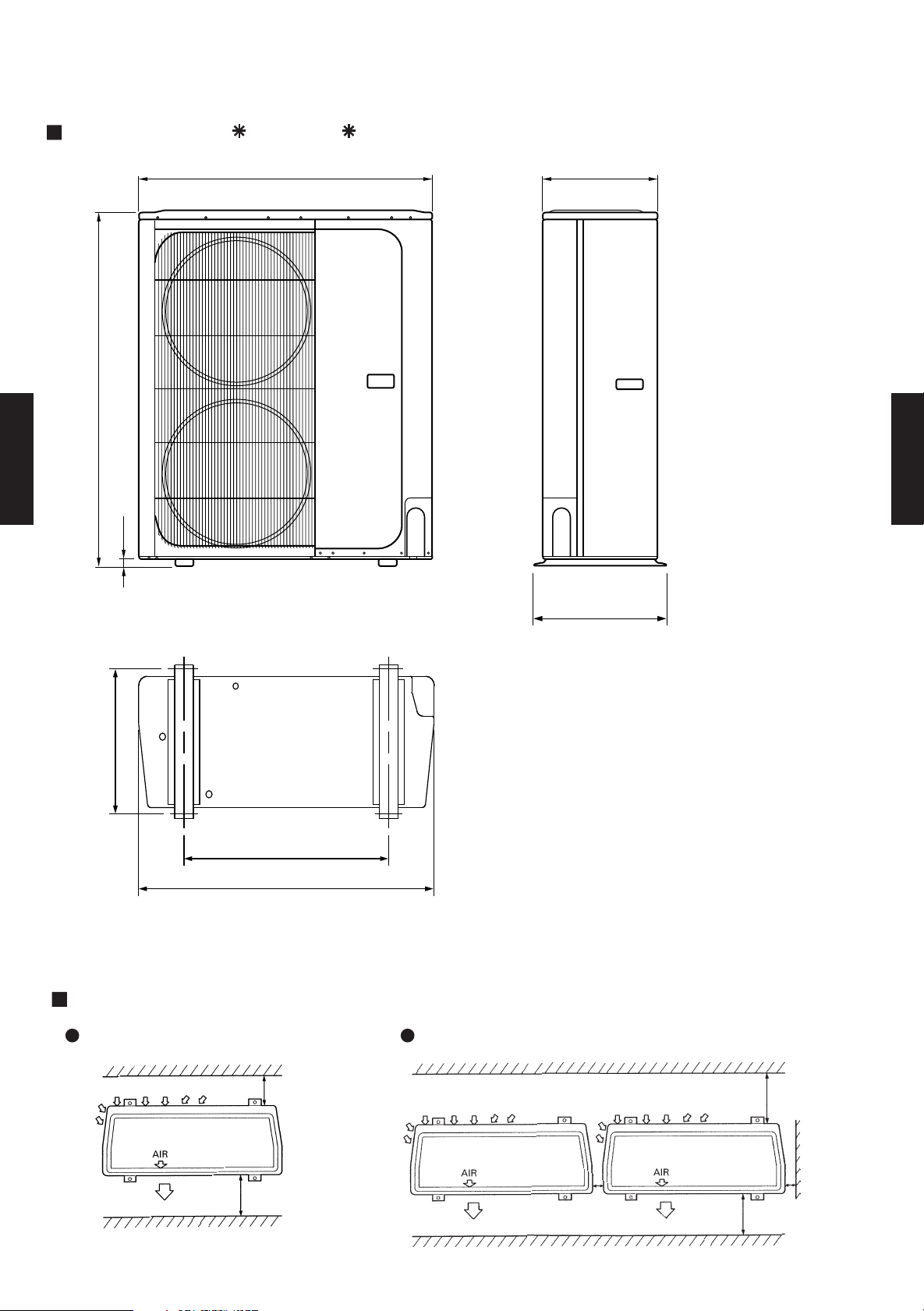
4-4-2. OUTDOOR UNIT
MODELS : AO 36A, AO 45A
940
370
(Unit : mm)
1,152
DUCT TYPE
DUCT TYPE
AR36 - 45
AR36 - 45
23
Front view
400
650
940
Bottom view
MOUNTING POSITION
When installing one unit
425
Side view
When installing multiple units
m
m
0
0
m
m
0
0
1
e
r
o
m
r
o
m
m
0
0
6
e
r
o
m
r
o
- (04 - 04) -
m
m
0
1
e
r
o
m
r
o
m
m
0
0
6
e
r
o
m
r
o
3
e
r
o
m
r
o
m
m
0
1
e
r
o
m
r
o
Page 6
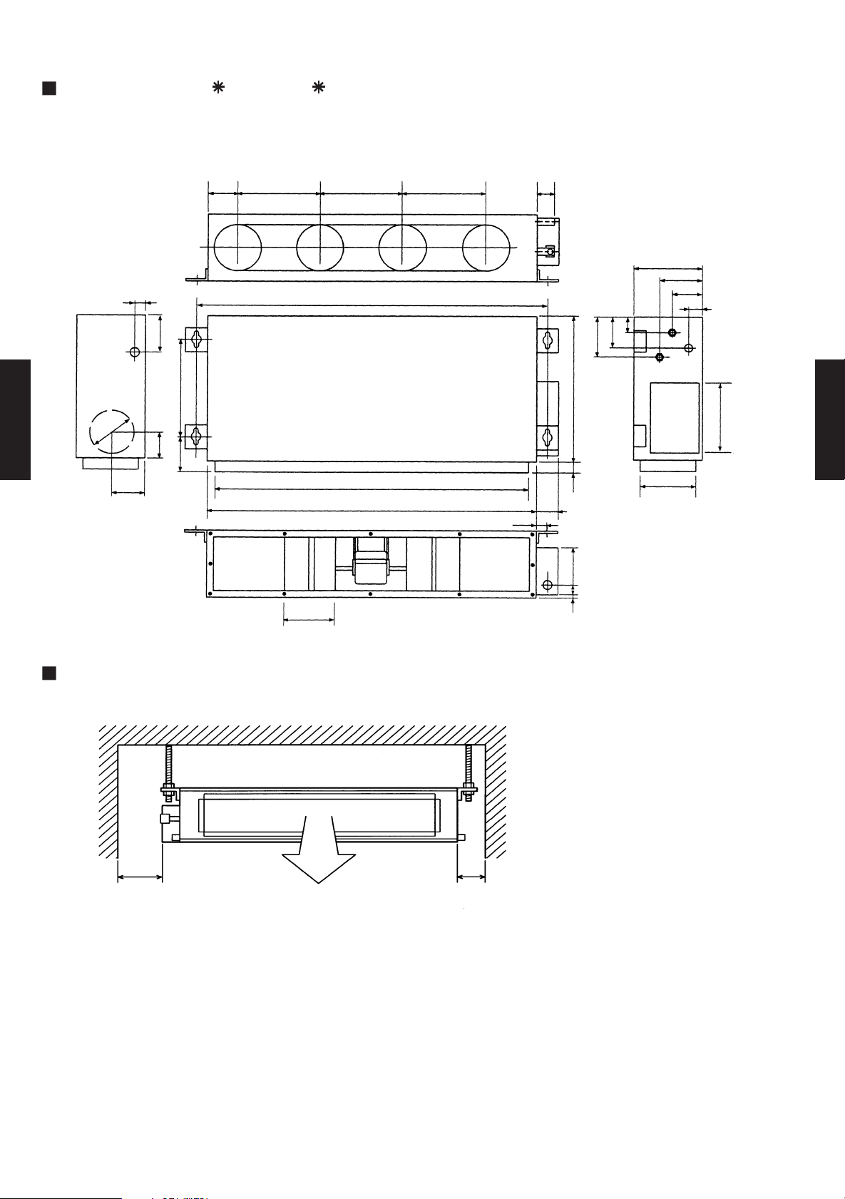
4-4-2. INDOOR UNIT
MODELS : AR 36A, AR 45A
(Unit : mm)
139 83264
26
197
46996
200
141
DUCT TYPE
AR36 - 45
117
220
264 264
1,177
1,063
1,135
42
75
270
96
58
26
196
126
243
700
382
DUCT TYPE
4066 184
68
205
AR36 - 45
MOUNTING POSITION
Strong and durable ceiling
Left
side
300 mm
or more
Indoor unit
Right
side
150 mm
or more
- (04 - 05) -
Page 7
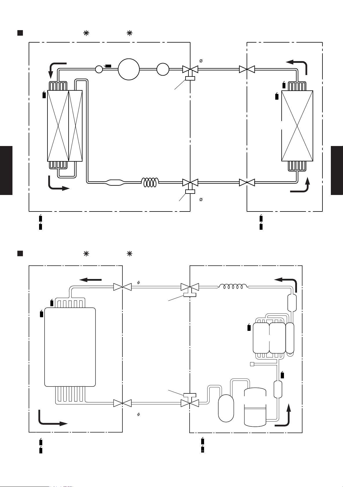
4-5. REFRIGERANT SYSTEM DIAGRAM
MODELS : AR 36A / AO 36A
OUTDOOR UNIT INDOOR UNIT
ACCUMULATOR
Charging valve
THO
MUFFLER
CONDENSER
THD
COMPRESSOR
Refrigerant pipe
19.05mm(3/4")
THPI
THR
EVAPORATOR
CAPILLARY TUBE
DUCT TYPE
AR36 - 45
DRYER
Charging valve
Refrigerant pipe
9.52mm(3/8")
DUCT TYPE
AR36 - 45
THD :THERMOSTAT (DISCHARGE TEMP)
THO :THERMOSTAT (OUTDOOR TEMP)
THR :
THERMISTOR (ROOM TEMP.)
THPI :
THERMISTOR (PIPE TEMP.)
MODELS : AR 45A / AO 45A
INDOOR UNIT OUTDOOR UNIT
Distributor
THPI
THR
Evaporator
Refrigerant pipe
9.52mm (3/8")
Charging valve
Charging valve
Capillary tube
Dryer
THO
Condenser
Thermistor
(Discharge gas)
THD
Muffler
THR :
THERMISTOR (ROOM TEMP.)
THPI :
THERMISTOR (PIPE TEMP.)
Compressor
Refrigerant pipe
19.05mm (3/4")
Accumulator
THD :THERMISTOR (DISCHARGE TEMP.)
THO :THERMISTOR (OUTDOOR TEMP.)
- (04 - 06) -
Page 8
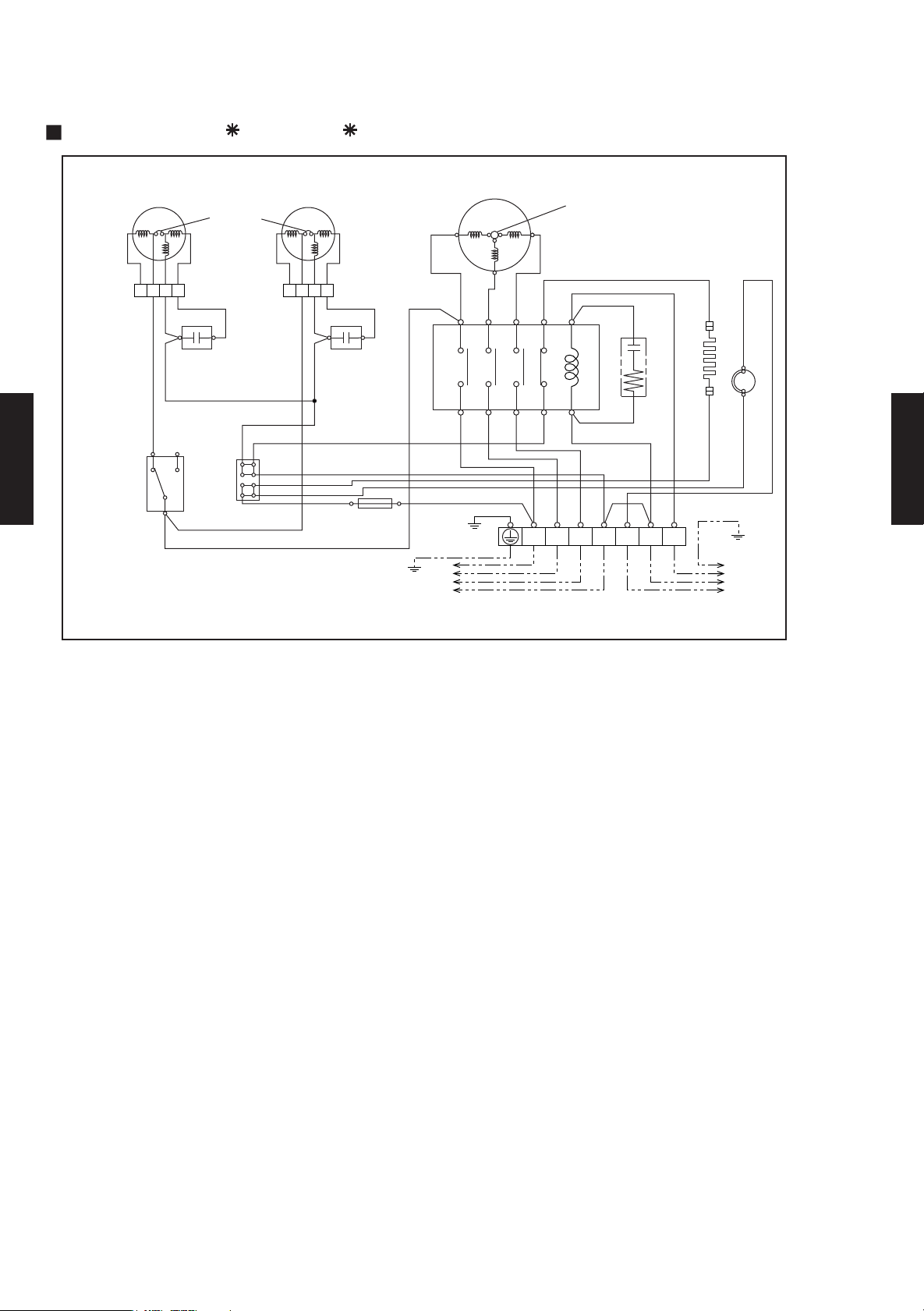
4-6. WIRING DIAGRAM
4-6-1. OUTDOOR UNIT
MODELS : AO 36A , AO 45A
FAN MOTOR
(UPPER)
CONNECTOR
WHITE
RED
LCH
OUTDOOR
DUCT TYPE
AR36 - 45
THERMOSTAT
THERMAL
PROTECTOR
CONNECTOR
FAN
CAPACITOR
WHITE
RED
BLACK
BLACK
TERMINAL
FAN MOTOR
(LOWER)
BLUE
BLACK
WHITEWHITE
FAN
CAPACITOR
BLACK
MAGNETIC RELAY
BLUE
BLUE
BLACK BLACK
FUSE
5A
COMPRESSOR
T1 T3
T2
WHITE
246 32 A1/A
135 31 A2/B
RED
WHITE
BLACK
GREEN/YELLOW
TERMINAL
TO POWER SUPPLY
(3N , 380-415V,50Hz)
RED
INTERNAL
OVERLOAD
PROTECTOR
BLUE
CR COMPOSITE
GRAY
BLUE
(N)
BROWN
2
13NTSR
TO INDOOR UNIT
(220-240V,50Hz)
THERMOSTAT
(DISCHARGE PIPE)
CRANKCASE HEATER
WHITE
WHITE
BLACK
DUCT TYPE
AR36 - 45
- (04 - 07) -
Page 9
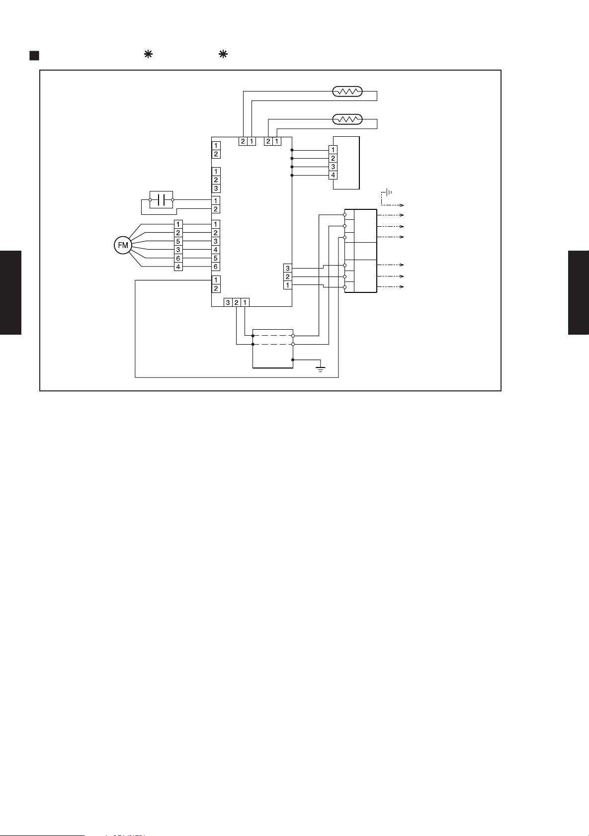
4-6-2. INDOOR UNIT
MODELS : AR 36A , AR 45A
GRAY
GRAY
BLACK
BLACK
CN7
CN8
FAN MOTOR
FAN
MOTOR
CAPACITOR
BLUE
PURPLE
PINK
RED
WHITE
BLACK
WHITE
WHITE
BLUE
PURPLE
PINK
RED
WHITE
BLACK
GRAY
CN15CN19 CN6
CN4CN5
CONTROL BOARD
CN17
CN1
Use T3.15A-250V
Fuse on F101
BLACK
DUCT TYPE
AR36 - 45
WHITE
FILTER
BOARD
THERMISTOR (PIPE TEMP.)
THERMISTOR (ROOM TEMP.)
WHITE
BLUE
RED
BLACK
BLACK
WHITE
RED
BLACK
GREEN
PCB
(RELAY)
TERMINAL
3
2
(N)
1
OUTDOOR
3
2
1
WHITE
UNIT
UNIT
CONTROL
REMOTE
CONTROL
TO OUTDOOR
TO REMOTE
CONTROL UNIT
DUCT TYPE
AR36 - 45
- (04 - 08) -
Page 10

4-7. CAPACITY TABLE
(°CDB) TC SHC PI TC SHC PI TC SHC PI TC SHC PI TC SHC PI TC SHC PI TC SHC PI TC SHC PI
0 11.99 9.46 2.51 12.22 9.50 2.57 12.46 9.53 2.60 12.82 9.93 2.63 1 2.97 9.86 2.65 13.25 9.6 8 2.68 13.37 9.59 2.70 13.4 9 9.99 2.71
5 11.56 9.20 2.82 11.83 9.25 2.87 1 2.11 9.28 2.90 12.54 9.7 5 2.95 12.71 9.69 2.98 13.0 3 9.56 3.02 13.17 9.48 3.04 13.30 9.89 3.06
10 11.07 8.88 3.10 11.34 8.91 3.17 11.62 8.98 3.21 12.09 9.49 3.27 12.28 9.46 3.30 12.6 0 9.35 3.35 12.75 9.28 3.38 12.89 9.70 3.40
15 10.55 8.57 3.40 10.80 8.62 3.48 11.08 8.68 3.52 11.52 9.20 3.59 11.70 9.17 3.62 12.0 3 9.08 3.68 12.19 9.02 3.71 12.33 9.46 3.74
20 10.51 8.29 3.73 10.74 8.33 3.79 11.00 8.37 3.83 11.42 8.87 3.91 11.60 8.84 3.95 11.9 4 8.77 4.01 12.10 8.72 4.04 12.25 9.16 4.07
25 10.93 8.54 3.23 11.20 8.58 3.27 11.45 8.63 3.30 11.88 9.11 3.35 12.06 9.07 3.37 12.3 9 8.98 3.41 12.54 8.92 3.43 12.68 9.35 3.45
30 10.23 8.15 3.55 10.52 8.20 3.57 10.76 8.29 3.60 11.17 8.77 3.66 11.35 8.75 3.68 11.6 8 8.67 3.73 11.84 8.63 3.75 11.99 9.07 3.78
35 9.52 7.81 3.86 9.70 7.87 3.88 9.95 7.91 3.91 10.32 8.39 3.97 10.50 8 .37 4.00 10.84 8.31 4.05 11 .00 8.28 4.08 11.16 8.7 4 4.10
40 8.66 7.41 4.19 8.79 7.45 4.21 9.00 7.47 4.23 9.36 7.96 4.29 9.54 7.95 4.32 9.87 7.91 4.39 10.03 7.90 4.42 10.19 8 .37 4.48
45 8.05 7.07 4.38 8.19 7.15 4.39 8.38 7.19 4.42 8.74 7.69 4.49 8.92 7.68 4.52 9.25 7.66 4.59 9.43 7.66 4.61 9.60 8.14 4.64
50 7.59 6.40 4.41 7.78 6.47 4.52 7.97 7.00 4.55 8.33 7.51 4.61 8.51 7.50 4.65 8.83 7.49 4.72 9.01 7.50 4.75 9.18 7.98 4.78
52 7.39 6.30 4.47 7.58 6.38 4.58 7.77 6.90 4.61 8.13 7.42 4.67 8.30 7.42 4.71 8.63 7.41 4.78 8.81 7.42 4.82 8.98 7.90 4.85
Outdoor temperature
15 °CWB
29 °CDB
21 °CWB
16 °CWB
27 °CDB
18 °CWB
19 °CWB
26 °CDB
23 °CDB
18 °CDB
12 °CWB
22 °CWB
Indoor temperature
32 °CDB
23 °CWB
30 °CDB
21 °CDB
(°CDB) TC SHC PI TC SHC PI TC SHC PI TC SHC PI TC SHC PI TC SHC PI TC SHC PI TC SHC PI
0 14.50 9.69 2.86 14.78 9.73 2.94 15.0 7 9.77 2.97 15.50 10.18 3.01 15.69 10.10 3 .03 16.02 9.92 3.06 16.1 7 9.83 3.08 16.32 10.23 3.10
5 13.98 9.43 3.22 14.30 9.47 3.28 14.6 5 9.50 3.32 15.17 9.99 3.37 15.38 9.93 3.40 15.76 9.7 9 3.45 15.93 9.71 3.47 16.09 10.13 3.49
10 13.38 9.10 3.54 13.72 9. 13 3.63 14.05 9.20 3.67 14.62 9.72 3.74 14.85 9.69 3.77 15. 24 9.57 3.83 15.42 9.51 3.86 15.60 9.94 3.88
15 12.76 8.78 3.89 13.06 8. 83 3.97 13.40 8.89 4.02 13.93 9.42 4.10 14.15 9.39 4.14 14. 55 9.30 4.21 14.74 9.25 4.24 14.91 9.69 4.27
20 12.71 8.49 4.27 12.99 8. 53 4.33 13.30 8.58 4.38 13.81 9.09 4.47 14.03 9.06 4.51 14. 44 8.98 4.58 14.63 8.93 4.62 14.81 9.39 4.65
25 13.22 8.75 3.70 13.54 8. 79 3.74 13.85 8.84 3.77 14.37 9.33 3.82 14.59 9.30 3.85 14. 98 9.20 3.90 15.17 9.14 3.92 15.34 9.58 3.94
30 12.38 8.35 4.05 12.73 8. 40 4.08 13.02 8.50 4.11 13.51 8.99 4.18 13.73 8.96 4.20 14. 13 8.88 4.26 14.32 8.84 4.29 14.51 9.30 4.31
35 11.51 8.00 4.41 11.73 8. 06 4.44 12.03 8.11 4.47 12.49 8.60 4.54 12.70 8.57 4.57 13. 11 8.52 4.63 13.30 8.49 4.66 13.50 8.96 4.69
40 10.48 7.59 4.79 10.63 7. 63 4.81 10.88 7.66 4.84 11.32 8.16 4.91 11.54 8.15 4.94 11. 93 8.11 5.02 12.14 8.09 5.05 12.33 8.57 5.11
45 9.74 7.25 5.01 9.90 7.33 5.02 10.14 7.36 5.05 10.57 7.88 5.12 10.79 7.87 5.16 11.19 7. 85 5.24 11.41 7.85 5.27 11.61 8.34 5.31
50 9.22 6.56 5.04 9.41 6.63 5.16 9.64 7.17 5.20 10.08 7.69 5.27 10.29 7.69 5.31 10.68 7.68 5.39 10.89 7.6 8 5.43 11.10 8.18 5.46
52 8.95 6.46 5.11 9.17 6.54 5.23 9.39 7.07 5.27 9.83 7.60 5.34 10.04 7.60 5.38 10.44 7.59 5.46 10.65 7.60 5.50 10.86 8.10 5.54
18 °CDB
12 °CWB
22 °CWB
Indoor temperature
32 °CDB
23 °CWB
30 °CDB
21 °CDB
Outdoor temperature
15 °CWB
29 °CDB
21 °CWB
16 °CWB
27 °CDB
18 °CWB
19 °CWB
26 °CDB
23 °CDB
4-7-1. COOLING
MODELS : AR 36A / AO 36A
MODELS : AR 45A / AO 45A
DUCT TYPE
AR36 - 45
DUCT TYPE
AR36 - 45
AFR: Air flow rate (m3/min)
TC : Total capacity (kW)
SHC: Sensible Heat capacity (kW)
PI : Power Input (kW)
- (04 - 09) -
Page 11

4-8. CAPACITY COMPENSATION FOR PIPE LENGTH
5 7.5 10 20 30 40 50
30 0.857 0.823 0.788
25 0.857 0.823 0.788
20 0.892 0.857 0.823 0.788
15 0.892 0.857 0.823 0.788
10 0.964 0.892 0.857 0.823 0.788
7.5 1.000 0.964 0.892 0.857 0.823 0.788
5 1.010 1.000 0.964 0.892 0.857 0.823 0.788
0 1.010 1.000 0.964 0.892 0.857 0.823 0.788
-5 1.002 0.992 0.956 0.885 0.851 0.816 0.781
-7.5 0.988 0.953 0.882 0.847 0.813 0.778
-10 0.949 0.878 0.844 0.809 0.775
-15 0.871 0.837 0.803 0.769
-20 0.864 0.830 0.796 0.763
-25 0.823 0.790 0.756
-30 0.816 0.783 0.750
PIPE LENGTH (m)
COOLING
Outdoor unit is
up-side
Outdoor unit is
bottom-side
HEIGHT DIFFERENCE (m)
AND HEIGHT DIFFERENCE
MODELS : AR 36A / AO 36A , AR 45A / AO 45A
COEFFICIENT OF COMPENSATION FOR PIPE LENGTH
COOLING
1.100
1.050
1.000
0.950
0.900
0.850
0.800
Coefficient of com pensation
0.750
0.700
0 10 20 30 40 5 0
COEFFICIENT OF COMPENSATION FOR HEIGHT DIFFERENCE
Pipe length (m)
DUCT TYPE
DUCT TYPE
AR36 - 45
- - - -
AR36 - 45
- - - -
- - -
- - -
- -
-
-
-
- -
-
-
- - -
- - -
-
- - - -
- (04 - 10) -
Page 12

4-9. ADDITIONAL CHARGE CALCULATION
REFRIGERANT AMOUNT g
REFRIGERANT TYPE
R22
2,400
PIPE LENGTH m
〜10
20 30 40 50(MAX)
ADDITIONAL CHARGE g
0 (Charge less)
300 600 900 1,200
30g/m
REFRIGERANT AMOUNT g
R22
3,150
REFRIGERANT TYPE
PIPE LENGTH m
〜20
30 40 50(MAX)
ADDITIONAL CHARGE g
0 (Charge less)
400 800 1,200
40g/m
MODELS : AR 36A / AO 36A
Refrigerant charge
MODELS : AR 45A / AO 45A
Refrigerant charge
DUCT TYPE
DUCT TYPE
AR36 - 45
AR36 - 45
- (04 - 11) -
Page 13

4-10. OPERATION RANGE
Indoor unit Outdoor unit Indoor temperature Indoor humidity Outdoor temperature
AR*36A
AR*45A
AO*36A
AO*45A
Cooling
Dry
18 to 32
℃
About 80% or less 0 to 52
℃
Model
Mode
Operation Range
DUCT TYPE
AR36 - 45
DUCT TYPE
AR36 - 45
- (04 - 12) -
Page 14

4-11. FAN PERFORMANCE AND AIR FLOW
30 40 50 60 70 100 125 150 175
m3/h 2,150 2,120 2,080 2,030 1,980 1,800 1,550 1,250 850
l/s 597 589 578 564 550 500 431 347 236
CFM 1,265 1,248 1,224 1,195 1,165 1,059 912 736 500
m3/h 2,050 2,020 1,980 1,930 1,880 1,700 1,450 1,130 -
l/s 569 561 550 536 522 472 403 314 -
CFM 1,206 1,189 1,165 1,136 1,106 1,000 853 665 -
m3/h 1,960 1,930 1,890 1,840 1,780 1,600 1,320 1,000 -
l/s 544 536 525 511 494 444 367 278 -
CFM 1,153 1,136 1,112 1,083 1,048 942 777 589 -
240V
STATIC PRESSRE (Pa)
FAN SPEED
Hi
Med
Low
MODELS : AR 36A / AO 36A
Q-h Characteris tic curve
200
DUCT TYPE
DUCT TYPE
AR36 - 45
150
Hi
Med
AR36 - 45
Lo
100
50
STATIC PRESSURE(Pa)
0
800 900 1000 1100 1200 1300 1400 1500 1600 1700 1800 1900 2000 2100 2200
AIR FLOW (m3/h)
Testcondition:NofilterandFanmode.
- (04 - 13) -
Page 15

MODELS : AR 45A / AO 45A
30 40 50 60 70 100 125 150 175
m3/h 2,200 2,170 2,130 2,080 2,030 1,840 1,600 1,300 900
l/s 611 603 592 578 564 511 444 361 250
CFM 1,295 1,277 1,254 1,224 1,195 1,083 942 765 530
m3/h 2,100 2,070 2,030 1,980 1,930 1,750 1,500 1,180 -
l/s 583 575 564 550 536 486 417 328 -
CFM 1,236 1,218 1,195 1,165 1,136 1,030 883 694 -
m3/h 2,000 1,970 1,930 1,890 1,830 1,650 1,370 1,050 -
l/s 556 547 536 525 508 458 381 292 -
CFM 1,177 1,159 1,136 1,112 1,077 971 806 618 -
240V
STATIC PRESSRE (Pa)
FAN SPEED
Hi
Med
Low
Q-h Characteris tic curve
200
DUCT TYPE
AR36 - 45
150
Hi
Med
DUCT TYPE
AR36 - 45
Lo
100
50
STATIC PRESSURE(Pa)
0
800 900 1000 1100 1200 1300 1400 1500 1600 1700 1800 1900 2000 2100 2200
AIR FLOW (m3/h)
Testcondition:NofilterandFanmode.
- (04 - 14) -
Page 16

4-12. NOISE LEVEL CURVE
HI 66.2 66.7 69.1 68.5 65.5 57.9 50.0
MED 65.8 65.1 67.5 66.9 62.4 55.1 47.5
LO 64.9 62.1 66.6 65.0 59.9 50.3 45.3
External Static
Pressre (Pa)
Blower
speed
63
125
250
500
1000
2000
4000
Octave Band Center Frequency (Hz)
AR 36A
Model name
Condition
50
HI 62.8 69.4 70.0 69.3 66.4 58.8 51.1
MED 66.5 68.2 68.4 68.0 64.7 57.3 49.5
LO 65.6 65.3 67.5 66.1 62.1 52.4 47.3
4000
250
500
1000
2000
Condition
Octave Band Center Frequency (Hz)
AR 45A
50
Model name
External Static
Pressre (Pa)
Blower
speed
63
125
4-12-1. INDOOR UNIT
COOLING
Sound Power Level(db)Of Medium Static Pressure Ducted A/C
AR 36A
AR 45A
DUCT TYPE
DUCT TYPE
AR36 - 45
Nots : Based on AMCA standard 300-96 in which the test setups are designed according
to the ANS/AMCA standsrd 210 & ANSI/ASHRAE standard.
AR36 - 45
- (04 - 15) -
Page 17

SOUND LEVEL CHECK POINT
DUCT TYPE
DUCT TYPE
AR36 - 45
AR36 - 45
- (04 - 16) -
Page 18

4-13. ELECTRIC CHARACTERISTICS
Voltage V
Frequency Hz
Current A
Input kW
Max Operating Current A
A
Main Fuse (Circuit breaker) Current A
Power Cable
mm2
*2)Limited wiring length m
Input kW
Full Load Amp. A
Input kW
Full Load Amp. A
Belt heater W
55
3N〜415V (Indoor unit:220-240V)
50
Cooling
7.5
4.57
9.0
AR*36A
AR*45A
AO*36A
AO*45A
Rated Value
Mode
6.6
40
4.00507.9
20
1.5
1.5
20
35
Indoor Fan Motor
0.15
0.15
0.67
0.67
*1) Wiring Spec
0.35 x 2
0.35 x 2
25(240V)
25(240V)
Outdoor Fan Motor
0.15 x 2
0.15 x 2
Starting Current
Indoor unit
Outdoor unit
Model Name
Power Supply
MODELS : AR 36A / AO 36A , AR 45A / AO 45A
DUCT TYPE
AR36 - 45
* Wiring Spec : Selected Sample
(Selected based on Japan Electrotechnical Standard and Codes Committee E0005)
*2 Limited Wiring length : This is the wiring length in case voltage descent is less than 2%.
When the wiring length becomes long, please select the wiring of a more larger diameter.
DUCT TYPE
AR36 - 45
- (04 - 17) -
Page 19

4-14. SAFETY DEVICES
PROTECTION FORM
AR*36A AR*45A
PCB FUSE - 3.15A 250V 3.15A 250V
FAN MOTOR PROTECTOR THERMAL PROTECTOR
150℃±5℃ OFF 150℃±5℃ OFF
PROTECTION FORM
AO*36A AO*45A
FUSE
(SIDE OF POWER SUPPLY TERMINAL)
- 5A 250V 5A 250V
FAN MOTOR PROTECTOR THERMAL PROTECTOR
150℃±5℃ OFF 150℃±5℃ OFF
COMPRESSOR
THERMAL PROTECTOR
OFF:145±5
℃
ON:61±9
℃
OFF:130±5
℃
ON:61±9
℃
INDOOR UNIT
OUTDOOR UNIT
DUCT TYPE
DUCT TYPE
AR36 - 45
AR36 - 45
- (04 - 18) -
Page 20

4-15.
EXTERNAL INPUT & OUTPUT
EXTERNAL
ELECTRICAL HEA
TER OUTPUT SETTING
You can control Electrical heater (Booster) by sychronization with heating operation.
When temperature is -10 to -3 degrees from Setpoint,External electrical heater is ON.
When temperature is -1 degrees from Setpoint,External electrical heater Stops.
Jumper wire (Indoor Unit)
This is used to continue indoor unit fan operation for 1 minute after thermo OFF in heating mode.
1 minute delay control set by cutting JM3 on PCB.
[Example]
+
Indoor
unit
1
2
-
CN15
(ORANGE)
DUCT TYPE
AR36 - 45
Field supplied
Power
Fuse
External Heater, other.
DUCT TYPE
AR36 - 45
Indoor
Operation
unit
Heating
Indoor
Stop
1min
Operation
unit fan
Stop
14V
CN15
(Output)
Please locate external a heater between the indoor unit and the ductwork.
Please be sure to use delay control of a fan.
0V
Supply air
CAUTION!
!
External
Heater
Indoor unit
Return air
- (04 - 19) -
Page 21

4-16. FUNCTION SETTING
1 Zone control setting
2 Room temperature correct coefficient of heating
3 Room temperature correct coefficient of heating
1 Forbidden
2 Forbidden
3 Fan delay setting
Rotary SW SW 2 Indoor unit number setting
JM1 Forbidden
JM2 Forbidden
JM3 Forbidden
Jumper wire
INDOOR UNIT
SW 1
SW 4
DIP SW
4-16-1. INDOOR UNIT
SWITCH POSITION
DUCT TYPE
AR36 - 45
Indoor unit control circuit board
DUCT TYPE
AR36 - 45
JM1
JM3
JM2
- (04 - 20) -
Page 22

4-16-2.SWITCH FUNCTION (INDOOR UNIT)
DIP SWITCH SETTING
1-1.Zone control setting
Zone control function can be selected by turning this switch ON/OFF.
Zonecontrol SETTING
( Factory setting)
SW 1-1 SW state
OFF Invalidity
ON Validity
1-2.Room temperature correct coefficient of heating.
Decide the heating temperature correct coefficient vale of heating.
HEAT TEMPERATURE CORRECTION
( Factory setting)
SW 1-2 SW state
OFF
ON
DUCT TYPE
AR36 - 45
OFF ON
ON ON +4 deg (Ceiling setting)
SW 1-3
OFF
OFF
+2 deg
-2 deg
0 deg (Floor setting)
DUCT TYPE
AR36 - 45
4-1.Dip SW 4-1setting forbidden
( Factory setting)
SW 4-1 OFF
4-2.Dip SW 4-2 setting forbidden
( Factory setting)
SW 4-2 OFF
4-3.Fan delay setting
This setting can be used when the auxiliary heater is mounted.
When the fan operation is stopped when the indoor unit is operating with an auxiliary heater,
the fan operation continues one minutes.
( Factory setting)
SW 4-3 SW state
OFF Invalidity
ValidityON
- (04 - 21) -
Page 23

ROTARY SWITCH SETTING
This switch can be used when group control system.
Set the indoor unit address in the 1,2,-,15 order.
( Factory setting)
SW 2 SW state
0 Single
1 - 15 Indoor unit address
JUMPER WIRE SETTING
1-1.JM 1, 2, 3 setting forbidden
( Factory setting)
JM stateJM 1
Connect
Disconnect
( Factory setting)
JM 2,3
Connect
DUCT TYPE
AR36 - 45
Disconnect
Forbidden
JM state
Forbidden
DUCT TYPE
AR36 - 45
EXTERNAL INPUT AND OUTPUT
Connector INPUT OUTPUT REMARKS
CN10 - ELECTRICAL HEATER
See external input/output
settings for details.
- (04 - 22) -
Page 24

Jumper Wire
Wired remote controller
DIP SW
SW1
Group control setting
(Unit address NO. setting)
SW2
4-16-3. WIRED REMOTE CONTROLLER
1
2
3
4
5 Forbidden
6 Indoor unit connection(Single/Multiple)
1 Cooling / Heat pump
2 Auto restart validity / invalidity
3 Forbidden
4 Defrost display
5 Forbidden
Memory backup switch
6
JM1 Forbidden
JM2 Forbidden
JM3 Forbidden
JM4
JM5 Forbidden
JM6 Forbidden
Auto change over validity / invalidity
DUCT TYPE
DUCT TYPE
AR36 - 45
AR36 - 45
SWITCH POSITION
Wired remote controller
N
N
O
O
2
2
345
1
Dip switch 1 Dip switch 2
4
5
3
6
1
6
- (04 - 23) -
Page 25

4-16-4. SW FUNCTION (WIRED REMOTE CONTRLLER)
DIP SWITCH SETTING
(1) SW1 setting
1-1 Unit address No. setting
Set remoto controller the SW1-6 toON.
Set the address number of additional indoor unit with remote controller SW1-(1-4).
For the address number of additional connected units, see the table below.
( Factory setting)
SW1-1 SW1-2 SW1-3 SW1-4 SW1-5 SW1-6 Indoor unit address
OFF OFF OFF OFF OFF OFF Single
OFF OFF OFF ON OFF ON 1
OFF OFF ON OFF OFF ON 2
OFF OFF ON ON OFF ON 3
OFF ON OFF OFF OFF ON 4
OFF ON OFF ON OFF ON 5
OFF ON ON OFF OFF ON 6
OFF ON ON ON OFF ON 7
ON OFF OFF OFF OFF ON 8
DUCT TYPE
AR36 - 45
ON OFF OFF ON OFF ON 9
ON OFF ON OFF OFF ON 10
ON OFF ON ON OFF ON 11
ON ON OFF OFF OFF ON 12
ON ON OFF ON OFF ON 13
ON ON ON OFF OFF ON 14
OFF OFF OFF OFF OFF ON 15
DUCT TYPE
AR36 - 45
SELF DIAGNOSIS
If [EE : EE] flashes at the remote controller current time displey, per-form[Self Diagnosis]
For the [Self Diagnosis] method, refer to the test operetion section of the installation instruction sheet.
The faulty air conditioner is also displayed.
Example [ 22 : 03 ] : Unit 03 room temperature sensor open
Faulty unit !
Error cord
DIP SW 1-5 setting forbidden.
( Factory setting)
DIP SW 1-5 OFF
Number of indoor unit conneection(Single/Multiple)
This is switchsd according to the number of connected indoor units.
NUMBER OF INDOOR UNIT CONNECTION
( Factory setting)
SW 1-6
OFF
ON
Number of indoor unit
One unit connection
Multiple unit connection
- (04 - 24) -
Page 26

(2) SW2 setting
2-1 Cooling only heat pump
Switching cooling only / heat pump
COOLING ONLY / HEAT PUMP SWITCH
( Factory setting, in case of Heat pomp Model)
( Factory setting in case of cooling only Model)
SW2-2
OFF
ON
2-2 Auto restart validity/invalidity
Selecting auto restart invalidity/validity in the case of it is ON, to set the SW2-6 ON.
AUTO RESTART
SW2-2
OFF
DUCT TYPE
AR36 - 45
ON
Operation system
Heat pump/Heat recovery
Cooling only
( Factory setting)
Auto restart
Invalidity
Validity
DUCT TYPE
AR36 - 45
2-3 DIP SW 2-3 setting forbidden
( Factory setting)
DIP SW2-5 OFF
2-4 Defrost display invalidity/validity
mark is displayed.
DEFROST
( Factory setting, in case of Heat pomp Model)
( Factory setting in case of cooling only Model)
SW2-4
OFF
ON
Defrost display
Invalidity
Validity
2-5 DIP SW 2-5 setting forbidden
( Factory setting)
DIP SW 2-5 OFF
2-6 Memory backup switch (wired remote controller only)
When installing, turn the SW2-6 ON.
MEMORY BACKUP SWITCH
( Factory setting)
DIP SW2-6
OFF
ON
Battery backup
Invalidity
Validity
- (04 - 25) -
Page 27

JUMPER WIRE SETTING
1 JM1 setting forbiden
( Factory setting)
JM1
Connect
Disconnect
JM state
Forbidden
2 JM2 setting forbiden
( Factory setting)
JM2
Connect
Disconnect
JM state
Forbidden
3 JM3 setting forbiden
( Factory setting)
JM3
Connect
Disconnect
DUCT TYPE
AR36 - 45
JM state
Forbidden
DUCT TYPE
AR36 - 45
4 Auto change over setting
selecting auto change over validity / invalidity
( Factory setting)
JM4
Auto change over
Connect
Disconnect
5 JM5 setting forbiden
( Factory setting)
JM5
Connect
Disconnect
6 JM6 setting forbiden
( Factory setting)
JM6
Connect
Disconnect
validity
invalidity
JM state
Forbidden
JM state
Forbidden
- (04 - 26) -
Page 28

4-17. OPTIONAL PARTS
SQUARE FLANGE (UTD - SF045T)
ROUND FLANGE (UTD - RF204)
Round flange is used when the fresh air duct is installed.
DUCT TYPE
DUCT TYPE
AR36 - 45
Air intake hole
Round flange
AR36 - 45
- (04 - 27) -
 Loading...