

Page 1
MULTI AIR CONDITIONER
WALL MOUNTED
type
Models
Indoor unit Outdoor unit
ASH9FMBD AOH19FSCV2
CONTENTS
SPECIFICATIONS
OUTLINE AND DIMENSIONS
REFRIGERANT SYSTEM DIAGRAM
CIRCUIT DIAGRAM
INDOOR PCB CIRCUIT DIAGRAM
ERROR CONTENTS
DISASSEMBLY ILLUSTRATION
PARTS LIST
STANDARD ACCESSORIES
. . . . . . . . . . . . . . . . . . . . . . .
. . . . . . . . . . . .
. . . . . . . . . . . . . . . . . . . . .
. . . . . . . . . . . . . . . . . . . .
. . . . . . . . . .
. . . . . . . . . . . . . . . . . . . . . . . . . . .
. . . . . . . . . . . . .
. . . . .
. . . . . . .
1
2
4
5
6
7
8
15
17
Page 2
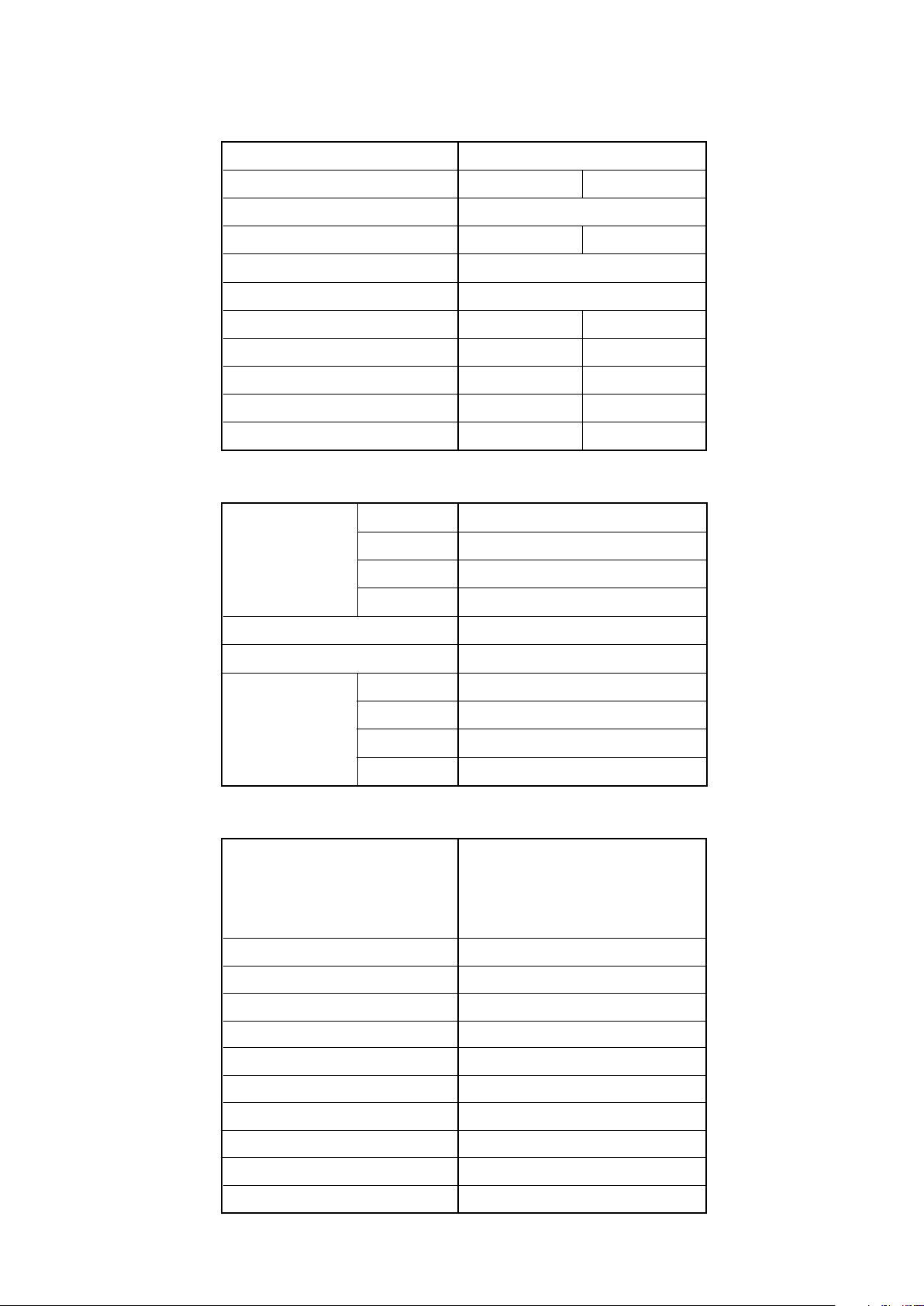
SPECIFICATIONS
ELECTRICAL DATA
TYPE
INDOOR UNIT
OUTDOOR UNIT
COOLING CAPACITY
POWER SOURCE
FREQUENCY
RUNNING CURRENT
INPUT WATTS
E.E.R.
MOISTURE REMOVAL
AIR CIRCULATION-High
INDOOR UNIT
FAN MOTOR
HIGH-SPEED
MED-SPEED
LOW-SPEED
QUIET
ASH9FMBD
AOH19FSCV2
2.85 kW
4.6 A
1.02 kW
2.79 kW/kW
1.0 L/hr
520 m3/hr
1,310 r.p.m.
1,190 r.p.m.
1,070 r.p.m.
960 r.p.m.
COOL
ASH9FMBD x 2
5.70 kW
230 V
50 Hz
8.6 A
1.89 kW
3.02 kW/kW
2.0 L/hr
520 m3/hr x 2
DIMENSIONS
WEIGHT
NOISE LEVEL
H x W x D
GROSS / NET
HIGH-SPEED
MED-SPEED
LOW-SPEED
QUIET
OUTDOOR UNIT
COMPRESSOR TYPE
COMPRESSOR DISCRIMINATION
POWER SOURCE
REFRIGERANT
ADDITIONAL CHARGE
CHARGELESS PIPE LENGTH
R410A
257 x 808 x 187 mm
10 kg / 8 kg
40 dB
37 dB
34 dB
31 dB
Hermetic type,
Permanent split condenser,
2 pole, Single phase,
Induction motor, Rotary
802 141 65B
230V - 50Hz
700 g x 2
10 g/m
7.5 m
MAXIMUM PIPE LENGTH
FAN MOTOR
DIMENSIONS
WEIGHT
NOISE LEVEL
H x W x D
Gross / Net
15 m
780 r.p.m.
700 x 900 x 330 mm
68 kg / 61 kg
52 dB
12006.03.13
Page 3
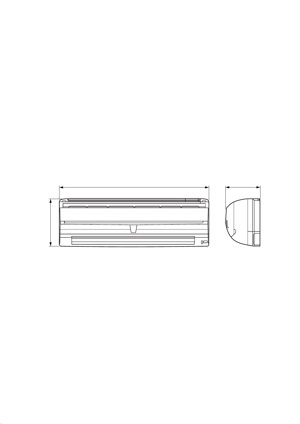
OUTLINE AND DIMENSIONS
INDOOR UNIT
Model : ASH9FMBD
(Unit : mm)
808
257
187
22006.03.01
Page 4
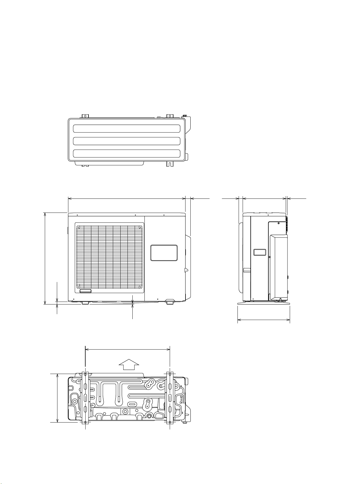
OUTDOOR UNIT
Model : AOH19FSCV2
(Unit : mm)
40900
33031 12
700
21
9
400
650
Air Flow
370
32006.03.01
Page 5
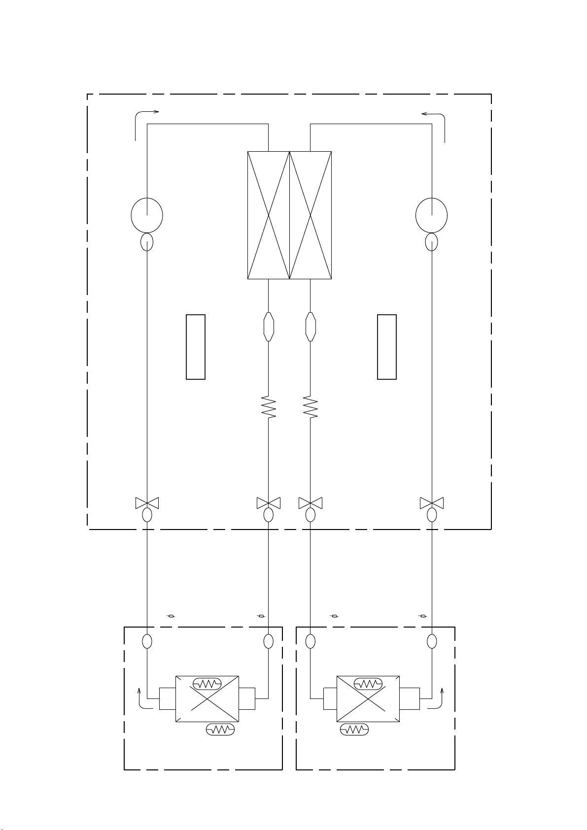
REFRIGERANT SYSTEM DIAGRAM
CONDENSER
COMPRESSOR-A
COMPRESSOR-B
STRAINER
U N I T A
CAPILLARY TUBE
3-WAY VALVE
2-WAY
VALVE
STRAINER
U N I T B
CAPILLARY TUBE
3-WAY
VALVE
2-WAY VALVE
OUTDOOR UNIT
REFRIGERANT PIPE
9.52mm(3/8")
REFRIGERANT PIPE
6.35mm(1/4")
REFRIGERANT PIPE
6.35mm(1/4")
REFRIGERANT PIPE
9.52mm(3/8")
INDOOR UNIT A
THERMISTOR
( PIPE TEMP. )
EVAPOLATOR
THERMISTOR
( ROOM TEMP. )
THERMISTOR
( ROOM TEMP. )
42006.03.01
THERMISTOR
( PIPE TEMP. )
EVAPOLATOR
INDOOR UNIT B
Page 6
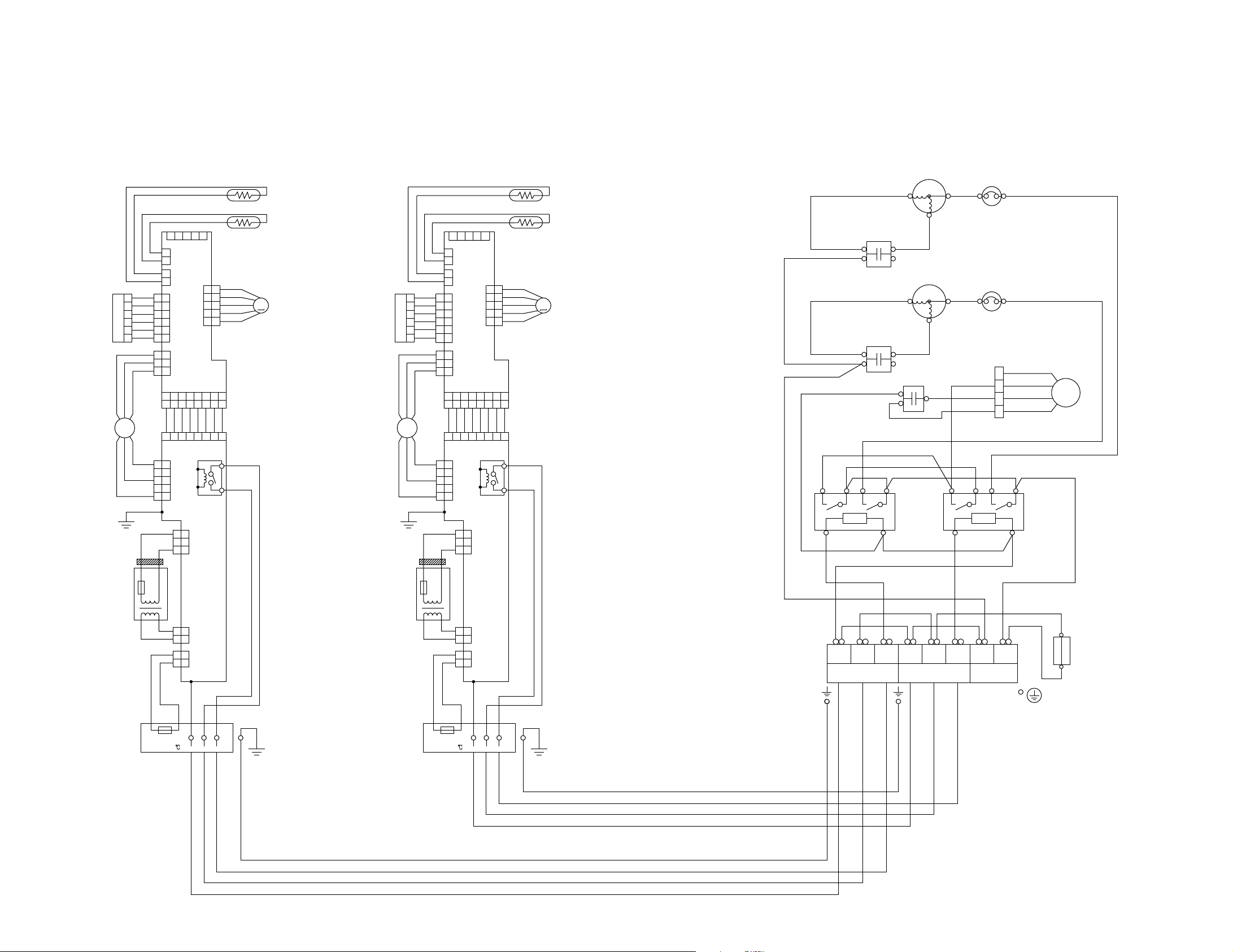
CIRCUIT DIAGRAM
Models : ASH9FMBD / AOH19FSCV2
INDICATOR PCB
FAN MOTOR
EMI FILTER
TRANSFORMER
CN201
RED
F M
BLACK
BLACK
BLACK
WHITE
6
WHITE
5
WHITE
4
WHITE
3
WHITE
2
1
WHITE
BLACK
WHITE
YELLOW
GREEN
GRAY
GRAY
1
2
1
2
6
6
5
5
4
4
3
3
2
2
RED
1
1
1
1
2
2
3
3
1 2 3 4 5 6 7 8
1 2 3 4 5 6 7 8
BLUE
1 2 3 4 5 6 7 8
5
5
4
4
3
3
2
2
1
1
W101
PURPLE
PURPLE
THERMAL
FUSE
RED
RED
GRAY
GRAY
TEST
2
1
CN2 CN3
CN8 CN4
WHITE
3
2
1
212
2
1
ROOM TEMPERATURE THERMISTOR
PIPE TEMPERATURE THERMISTOR
5
3
4
CN1
BLUE
10
10
PINK
9
9
YELLOW
8
8
CN5
ORANGE
7
7
RED
6
6
M
STEP MOTOR
CONTROLLER PCB
CN6
WHITE
WHITE
CN105
WHITE
WHITE
WHITE
WHITE
3
K103
4
RELAY
3
2
1
POWER SUPPLY PCB
1
CN104 CN102
2
1
CN103
W103
RED
WHITE
BLACK
INDOOR UNIT
CN201
INDICATOR PCB
RED
FAN MOTOR
TRANSFORMER
F M
BLACK
EMI FILTER
BLACK
BLACK
WHITE
6
WHITE
5
WHITE
4
WHITE
3
WHITE
2
1
WHITE
BLACK
WHITE
YELLOW
GREEN
GRAY
GRAY
RED
PURPLE
PURPLE
THERMAL
RED
GRAY
6
5
4
3
2
1
1
2
3
5
4
3
2
1
FUSE
RED
GRAY
1
2
1
2
6
5
4
3
2
1
1
2
3
1
1
BLUE
1
5
4
3
2
1
W101
TEST
2
3
4
1
CN1
CN2 CN3
CONTROLLER PCB
CN8 CN4
CN6
3 4 567 8
2
3 4 567 8
2
WHITE
WHITE
WHITE
3 4 567 8
2
CN105
CN101
3
3
2
2
1
1
212
1
2
2
1
1
W103
WHITE
ROOM TEMPERATURE THERMISTOR
PIPE TEMPERATURE THERMISTOR
5
BLUE
10
10
PINK
9
9
YELLOW
8
8
CN5
ORANGE
7
7
RED
6
6
WHITE
WHITE
WHITE
WHITE
K103
M
STEP MOTOR
3
4
RELAY
POWER SUPPLY PCB
CN104 CN102
CN103
RED
BLACK
WHITE
OUTDOOR UNIT
COMP .B
R
COMP .
CAPACITOR B
RED
WHITE
COMP .A
R
COMP .
CAPACITOR A
RED
WHITE
FAN
CAPACITOR
RED
GRAY
1
32
A B
56
WHITE
WHITE
RED
WHITE
BLACK
WHITE BLUE
1(N) 2 3 1(N) 2 3 N
YELLOWBLACKBLUE
C
S
OVERLOAD
PROTECTOR
BLACKBLACK
C
S
OVERLOAD
PROTECTOR
FAN
BLUE
RED
BLACK
WHITE
RED
BLACK
WHITE
GRAY
GRAY
14
432
MOTOR
FM
RELAYRELAY
56
PINK
GRAY
BLACK
FUSE
L
T5A250V
POWERUNIT BUNIT A
2006.03.01
2 3
THERMAL
FUSE 103
TERMINAL
(N)
1
THERMAL
FUSE 103
TERMINAL
UNIT A UNIT B
1
(N)
2 3
5
Page 7

INDOOR PCB CIRCUIT DIAGRAM
Model : ASH9FMBD
POWER TRANSFORMER
UL1015 AWG22
GREEN
EZ-030HSE-T
PRIMARY
W101
E
GREEN
F101
T 3.15A
250V
TERMINAL BOARD
TERMAL FUSE
SECONDARY
CN102-3 PURPLE
CN102-1 PURPLE
CN104-1 RED
CN104-2 RED
CN102 B2P3-VH-B
C102
4700P
C103
0.1
VA101
470V
C101
4700P
CN104 B2B-XH-AM
FH102
FH101
W103
BLACK
UL1015 AWG14 BLACK
UL1015 AWG22 WHITE
2
1
TERMAL BOARD
UL1015 AWG18 RED
POWER SOURCE
230V
3
50Hz
GREEN / YELLOW
103
TEMPERATURE FUSE
CN103-1 GRAY
CN103-2 GRAY
POWER SUPPLY PCB
EZ-002SWSE-P ( F )
CN103 B2B-XASK-1-A
C104
0.1
R102 1.0K
<1/2W>
+
C109
10/
50V
FAN CAPACITOR
VA102
470V
12V
Q101
2SD880
+
D104
MTZJ15B
D102 1SR139
L101
SS11V-10062
D101
S1VB20
R101
10K
<1/4W>
C105
2200
/35V
C110
7.0
CN101 B3P5-VH-B
SSR101
G3MC-201PL-VD DC12V
12V
D103
1SR139
C106
2200
/25V
3
4
K103
G4A-1A-E-PS
+
I C101
7805
I O
G
2
1
C108
0.1
<F>
CN101-1
CN101-3
CN101-5
12V
BLACK
YELLOW
WHITE
FAN MOTOR
12V5V
CN105
PHR-8
F M
CN105-1
CN105-2
CN105-3
CN105-4
CN105-5
CN105-6
CN105-7
CN105-8
UL1061 AWG26 x 8
CN7-1
CN7-2
CN7-3
BLUE
WHITE
WHITE
WHITE
WHITE
WHITE
WHITE
WHITE
RED
WHITE
BLACK
CN6-1
CN6-2
CN6-3
CN6-4
CN6-5
CN6-6
CN6-7
CN6-8
CN8
S3P-VH
CONTROLLER PCB ASSEMBLY ( MAIN PCB )
EZ-00205WSE-C ( F )
R2 1.0K
<1/10W>
5V
3
2
I C4-6 uLN2003
6
I C4-7 uLN2003
Q2
DTC124EUA
3
2
C2 0.1
<F>
R3, R34, R5, R35
10K <1/10W> x 4
C7
10/25V
5V
R8
10K
<1/10W>
C9 0.01
<R>
R33 10K
<1/10W>
uPD780024ASGB-X02-8ET-A
1
+
5V
R12
10K
<1/10W>
5V
5V
R1
10K
<1/10W>
C1 0.1
<F>
ROOM TEMPERATURE CORRECTION 1
( HEATING OPERATION )
ROOM TEMPERATURE CORRECTION 2
( HEATING OPERATION )
AUTO RESTART
REMOTE CONTROL UNIT CUSTOM CODE
12V
R6 1.0K
<1/8W>
C8
0.1
<F>
12 5
CN6
B8B-PH-K-S
C11
0.1
<F>
5V
BZ1
12V
PKM13EPY-4000
B Z
R14 10K
<1/10W>
JP1
JP2
JP3
JP4
Q1
DTC124EUA
1
3
2
1
R7 4.7K
<1/8W>
11
I C4-5 uLN2003
10 7
I C2
BR93LC46
CS
8
VCC
D0
4
SK
6
TEST
D1
5
GND
NC
EEPROM
Q3
DTC124EUA
1
2
3
7
I C 1
44
P75
29
XT2
P25
RESET
2
19
P57
28
24
P11
25
P10
13
P36
38
P03
12
P35
11
P34
35
P00
P56
P55
P54
52
P47
51
P46
P45
50
49
P44
48
P43
47
P42
P41
46
P40
45
32
X1
CST8.38MHz
8
7
6
5
R30 1.0K
<1/10W>
C25
0.1
<F>
C22
0.1
<F>
C21
0.1
<F>
C16
1000P
<R>
1
3
P02
37
P20
14
15
P21
16
P22
43
P74
27
AVD0
10
VDD0
20
VDD1
26
AVREF
23
P12
22
P13
30
XT1
9
VSS0
34
VSS1
21
AVSS
4
P53
36
P01
1
P50
2
P51
3
P52
5V
42
P73
41
P72
40
P71
P70
39
17
P23
P24
18
31
I C
X1 X2
33
R25 390
<1/10W>
R24 390
<1/10W>
12V
9
5V
5V
R20 - R23
10K <1/10W> x 4
5V
R19
10K
<1/10W>
16
2
14
4
8
R29
10K
<1/10W>
R28 10K
<1/10W>
RESET 4
I C3
BD4742G
I C4-1 uLN2003
15
I C4-2 uLN2003
I C4-3 uLN2003
13
I C4-4 uLN2003
SW1
5V
C27
5
2
0.1
1
<F>
3
R18 47
<1/10W>
R17 330 <1/10W>
R16 330 <1/10W>
R15 330 <1/10W>
MANUAL AUTO
SWITCH
5V
R27 10K
<1/10W>
(1%)
R26 49.9K
<1/10W>
(1%)
5V
12V
CN2 150-103-86176
CN2-1
CN2-2
CN3-1
CN3-2
CN3 150-503-96077
CN1 B5P-SHF-1AA
CN1-1
CN1-2
CN1-3
TEST
CN1-4
CN1-5
CN4 B6B-PH-K-S
RED
CN4-1
WHITE
CN4-4
WHITE
CN4-4
WHITE
CN4-4
WHITE
CN4-5
WHITE
CN4-6
UL1061 AWG26 x 6
CN5 53325-0510
CN5-6
CN5-7
CN5-8
CN5-9
CN5-10
UL1061 AWG26 x 5
BLACK
BLACK
GRAY
GRAY
RED
ORANGE
YELLOW
PINK
BLUE
ROOM TEMPERATURE THERMISTOR
PIPE TEMPERATURE THERMISTOR
INDICATOR PCB
EZ-002SWSE-D (F)
R201 47
<1/4W>
1
2
3
C202
0.1
<F>
OPERATE
4
TIMER
5
SWING
6
CN201
M
X201
GP1UM261RK
+
DATA
C201
47/
10V
D201 SLR-325<VC>
D202 SLR-325<MC>
D203 SLR-325<DC>
LOUVER
VCC
GND
5V
RED
GREEN
ORANGE
2006.03.01
OUTDOOR UNIT
TO EARTH TERMINAL STRIP
6
Page 8

ERROR CONTENTS
INDOOR UNIT
: Fast flashing : Slow flashing
Operation lamp
Timer lamp : Green lamp
: Red lamp
Small division indicationLarge division indication
Error contents Error contents
circuit board error
(indoor unit )
thermistor error Red lamp
control unit error Red lamp (4 times) MANUAL AUTO button error Red lamp
(indoor unit ) Green lamp
LED indication LED indication
Red lamp
Green lamp
(2 times) thermistor error (room temp.) Red lamp
Green lamp Green lamp (2 times)
----- -----
thermistor error (heat exchanger) Red lamp
Green lamp (3 times)
Green lamp
power source Hz decision error Red lamp
Green lamp (4 times)
-----
(2 times)
fan motor error Red lamp (6 times) lock error Red lamp
(indoor unit) Green lamp
r.p.m error Red lamp
When an error occurs, "Large division indication" is indicated first.
Secondly, "Small division indication" is indicated by pushing "Test" button of remote controller.
72006.03.01
Green lamp
Green lamp (3 times)
(2 times)
Page 9

DISASSEMBLY ILLUSTRATION
Model : ASH9FMBD
850
240
63
Air cleaning filter
Model : UTR-FA04-2
(ION DEODORANT FILTER)
74
777
Air cleaning filter
Model : UTR-FA04-1
(ELECTRIC FILTER)
74
759-1
82006.03.01
Page 10

151
401
236
233
815
875
196
158
108
146
184
652-1
872
668
875
873
874
127
767-1
164
109
876
281
764
169
522-1
122
523
283
323
69
323
65
440
92006.03.01
Page 11

Model : AOH19FSCV2
4
1
10
2
5
9
6
3
102006.03.01
Page 12

Model : AOH19FSCV2
12
19
13
14
11
24
18
23
15
25
112006.03.01
Page 13

Model : AOH19FSCV2
33
29
34
30
32
31
40
28
28
27
38
41
39
37
122006.03.01
Page 14

Model : AOH19FSCV2
49
48
48
43
50
44
46
51
47
53
52
53
45
132006.03.01
Page 15

Model : AOH19FSCV2
58
59
60
61
62
63
28
62
62
63
63
142006.03.01
Page 16

PARTS LIST
INDOOR UNIT
Ref.
No.
63
65
69
74
108
109
122
127
146
151
158
164
169
184
196
233
236
240 Remote Control Unit 9312058037
281 BRACKET(PIPE) 9330011014
283 Bushing-A 9303529010
Description
Front Panel Assy 9312172085
Flow Control Panel-Z 9306058043
Louver-A 9306055028
Filter 9305444014
Base 9309755062
Casing 9306052027
Shaft Holder-B 9303066010
Drain Hose Assy 9305550029
Evaporator Assy 9373044017
Control Box 9330007017
Connecting Pipe Assy 9306416010
Fan Motor Assy-IN 9601844013
Cross-Flow Fan Assy 9307836015
Thermistor Spring 313728262708
Clamp SKB-150 313035356905
Power Transformer 9701803026
Controller PCB Assy
(EZ-00205WSE-C)
Part No.
ASH9FMBD
9704865045
Ord.
Q'ty
323 Louver-B 9306056025
401 Wall Hook Bracket 9304358008
440 Flow Control Panel-U 9306057046
522-1 Gear-A 9306062002
523 Gear Bracket 9306407001
652-1 Thermistor Holder Pipe 313714262805
668 Screw w/Washer 9372808023
759-1 Intake Grille 9330002012
764 Drain Cap Assy 9304150008
767-1 Bottom Cover 9330004016
777 CLAMPER(GRILL) 9306755010
815 Terminal 9900040055
850 Window (Receiver) 9330003019
872 Indicator Case 9330009011
873 Lamp Cover 9330014015
874 Control Box Cover 9330008014
875 PCB Assy (Power+Indicator) 9704871053
876 Step Motor 9900139018
152006.03.01
When you order parts, please make a photocopy of this page
and fill the number of the parts in the "Order" column.
Page 17

OUTDOOR UNIT
Ref.
No.
Description
Part No.
AOH19FSCV2
1 Top Panel Sub Assy 9374417018
2 Front Panel S 9374094080
3 Fan Guard 9374330010
4 Grip Side 9374173013
5 Service Panel Sub Assy 9374415045
6 Right Panmel 9374599042
9 Grip 9374172016
10 Print Net S 9374255047
11 Propeller Fan Assy 9366378013
12 Motor, Induction 9601671060
13 Condenser A Assy 9374433100
14 Separate Wall S 9374135042
15 Base Assy 9374166121
18 Cap Foot 9374345014
19 Motor Bracket Sub Assy 9374418084
23 Compressor Cover A 9375323028
24 Compressor Cover B 9374431076
25 Compressor Cover C 9372067055
27 Compressor Plate Assy 9375221010
28 Compressor Assy 9373010029
Ord.
Q'ty
29 Discharge Pipe A1 9372179420
30 Discharge Pipe B1 9372180334
31 3-Way Valve Assy 9375103019
32 2-Way Valve Assy 9375102012
33 Suction Pipe A1 9372176351
34 Suction Pipe B1 9371275253
37 Condensing Pipe A1 9372232088
Condensing Pipe B1
38
Capillary A Assy
39
40 Capillary B Assy
41 Joint Pipe (Valve) A1
Control Box A
43
Fuse Holder
44
Control Box D
45
Fuse
46
Band (Capacitor)
47
Capacitor, Plastic (Comp.)
48
Capcitor, Plastic (Fan)
49
Relay
50
Terminal
51
9372231111
9375297046
9375298050
9372178164
9375216016
0501456016
9375219017
0600376086
9352123009
9900269043
9900270049
9900239015
9900203047
Clamp (Cord) C
52
Clamp (Cord)
53
Special Nut M5
58
Terminal Cover (Comp.)
59
Terminal Gasket (Comp.)
60
OCR Assy
61
Special Nut
62
Rubber Seat (Comp) A
63
Emblem Rear
---
9359677000
9356857009
313199233602
9302419008
9351505011
9311143000
9355091008
9351507015
9372171011
162006.03.13
When you order parts, please make a photocopy of this page
and fill the number of the parts in the "Order" column.
Page 18

STANDARD ACCESSORIES
INDOOR UNIT
Name and Shape Q'ty
Wall hook bracket
Remote control
unit
Battery (penlight)
1 set
Remote control unit
holder case
Part No.
1
1
9304358008
9312058037
(AR-JE06)
0600185534
Cloth tape
Tapping screw (big)
( 4 x 25)
Tapping screw (small)
( 3 x 12)
1
1
8
2
9312653010
9310519004
0700076046
0700019036
OUTDOOR UNIT
Name and Shape Q'ty Part No.
Putty
1
172006.03.01
303020200114
Page 19

0603G3042
 Loading...