

Page 1
R410A
INDOOR UNIT
1.
MULTI TYPE : 2ROOM TYPE
AR 9LUAB AB 14LBAJ
AR 9LUAP AB 18LBAJ
AR 12LUAD
AR 12LUAL AS A07LACM
AR 14LUAD AS A09LACM
AR 14LUAL AS A12LACM
AR 18LUAD AS A14LACM
AR 18LUAL AS A18LACM
AU 12LBAB
AU 14LBAB
AU 18LBAB
D2D_MU012E/01
2007.05.28
Page 2
1. FEATURE
1-1. MODEL
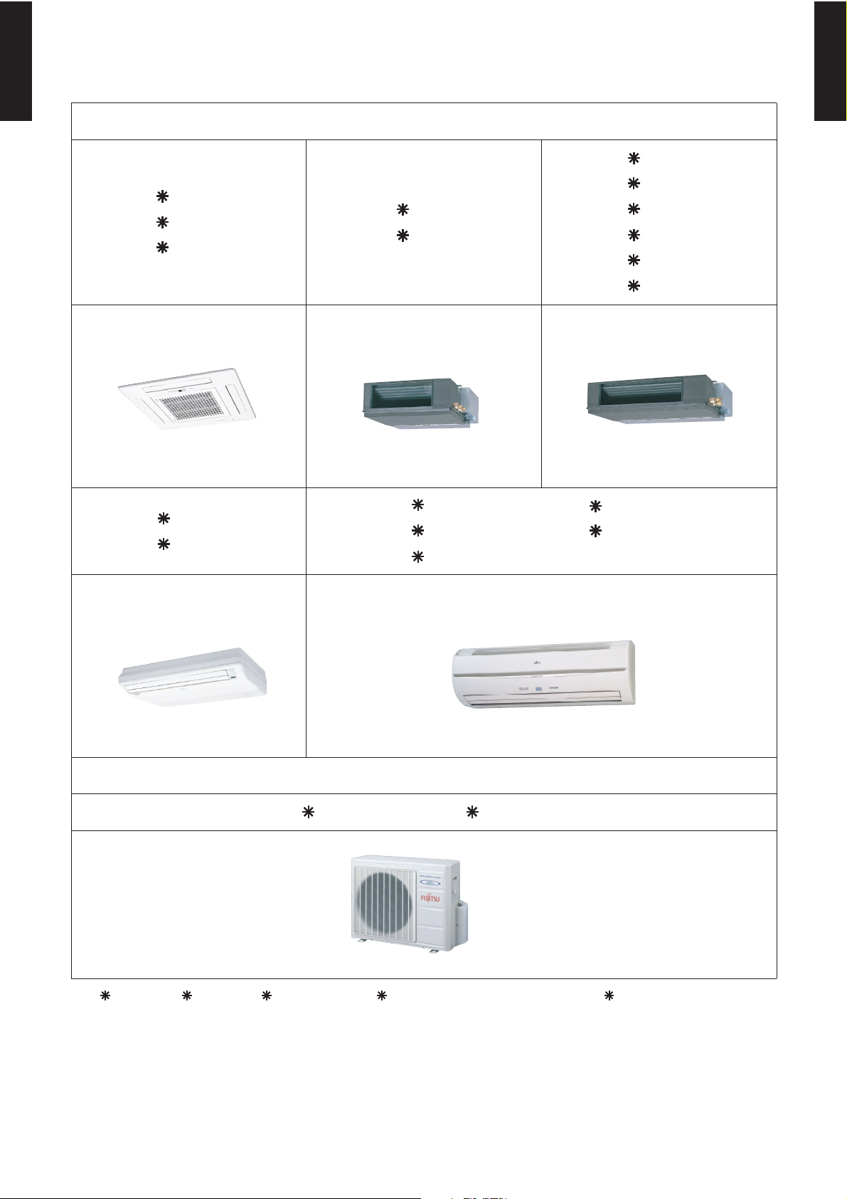
MULTI TYPE
2ROOM TYPE
INDOOR UNIT
AR 12LUAD
MULTI TYPE
2ROOM TYPE
AU 12LBAB
AU 14LBAB
AU 18LBAB
Cassette Type (Compact)
AB 14LBAJ
AB 18LBAJ
Ceiling (Universal) Type
AR 9LUAB
AR 9LUAP
Duct Type (Small)
AS A07LACM
AS A09LACM
AS A12LACM
Wall Mounted Type
AR 12LUAL
AR 14LUAD
AR 14LUAL
AR 18LUAD
AR 18LUAL
Duct Type
AS A14LACM
AS A18LACM
OUTDOOR UNIT
AO 18LMAK2 / AO 24LMAM2
AU 18L, AR 18L, AB 18L, and AS 18L cannot connect to AO 18L2
- (01 - 01) -
Page 3
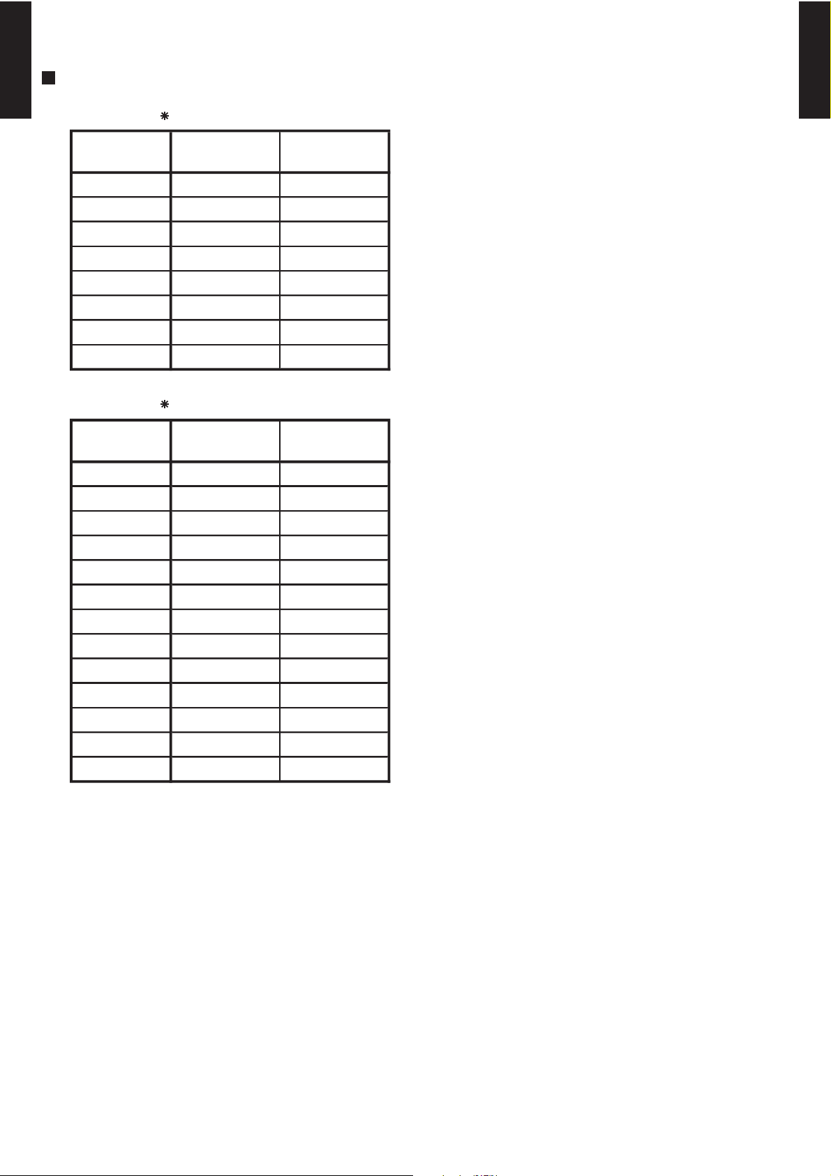
INDOOR UNIT CONNECTION PATTERN
CONNECTION
PATTERN
No.1
Indoor unit
No.2
Indoor unit
CONNECTION
PATTERN
No.1
Indoor unit
No.2
Indoor unit
MULTI TYPE
2ROOM TYPE
MODEL : AO 18L2
1 7,000 7,000
2 7,000 9,000
3 7,000 12,000
4 7,000 14,000
5 9,000 9,000
6 9,000 12,000
7 9,000 14,000
8 12,000 12,000
MODEL : AO 24L2
1 7,000 7,000
MULTI TYPE
2ROOM TYPE
2 7,000 9,000
3 7,000 12,000
4 7,000 14,000
5 7,000 18,000
6 9,000 9,000
7 9,000 12,000
8 9,000 14,000
9 9,000 18,000
10 12,000 12,000
11 12,000 14,000
12 12,000 18,000
13 14,000 14,000
- (01 - 02) -
Page 4

1-2. SELECT FUNCTION
MULTI TYPE
2ROOM TYPE
1-2-1. INDOOR UNIT
MODEL : AS A07L, AS A09L, AS A12L, AS A14L, AS A18L
Auto restart
When the air conditioner power was temporarily turned off by a power failure etc.
It restarts automatically after the power recovers.
(Operated by setting before the power failure.)
Remote control unit signal code setting
The Remote control unit signal code can be changed by four patterns.
MODEL : AR 9L, AR 12L, AR 14L, AR 18L
Auto restart
When the air conditioner power was temporarily turned off by a power failure etc.
It restarts automatically after the power recovers.
(Operated by setting before the power failure.)
High static pressure function setting
In case of installing in high static, you can maximize(minimize) air flow and noise.
MULTI TYPE
2ROOM TYPE
Fresh air output
You can control sub fan by synchronization with fan operation of indoor unit.
MODEL : AU 12L, AU 14L, AU 18L
Auto restart
When the air conditioner power was temporarily turned off by a power failure etc.
It restarts automatically after the power recovers.
(Operated by setting before the power failure.)
Remote control unit signal code setting
The Remote control unit signal code can be changed by four patterns.
MODEL : AB 14L, AB 18L
Auto restart
When the air conditioner power was temporarily turned off by a power failure etc.
It restarts automatically after the power recovers.
(Operated by setting before the power failure.)
Remote control unit signal code setting
The Remote control unit signal code can be changed by four patterns.
1-2-2. OUTDOOR UNIT
MODEL : AO 18L2, AO 24L2
Current capacity setting
When the current contacted is insufficient, you can change the current capacity.
- (01 - 03) -
Page 5
2. REMOTE CONTROLLER
MULTI TYPE
2-1.
2ROOM TYPE
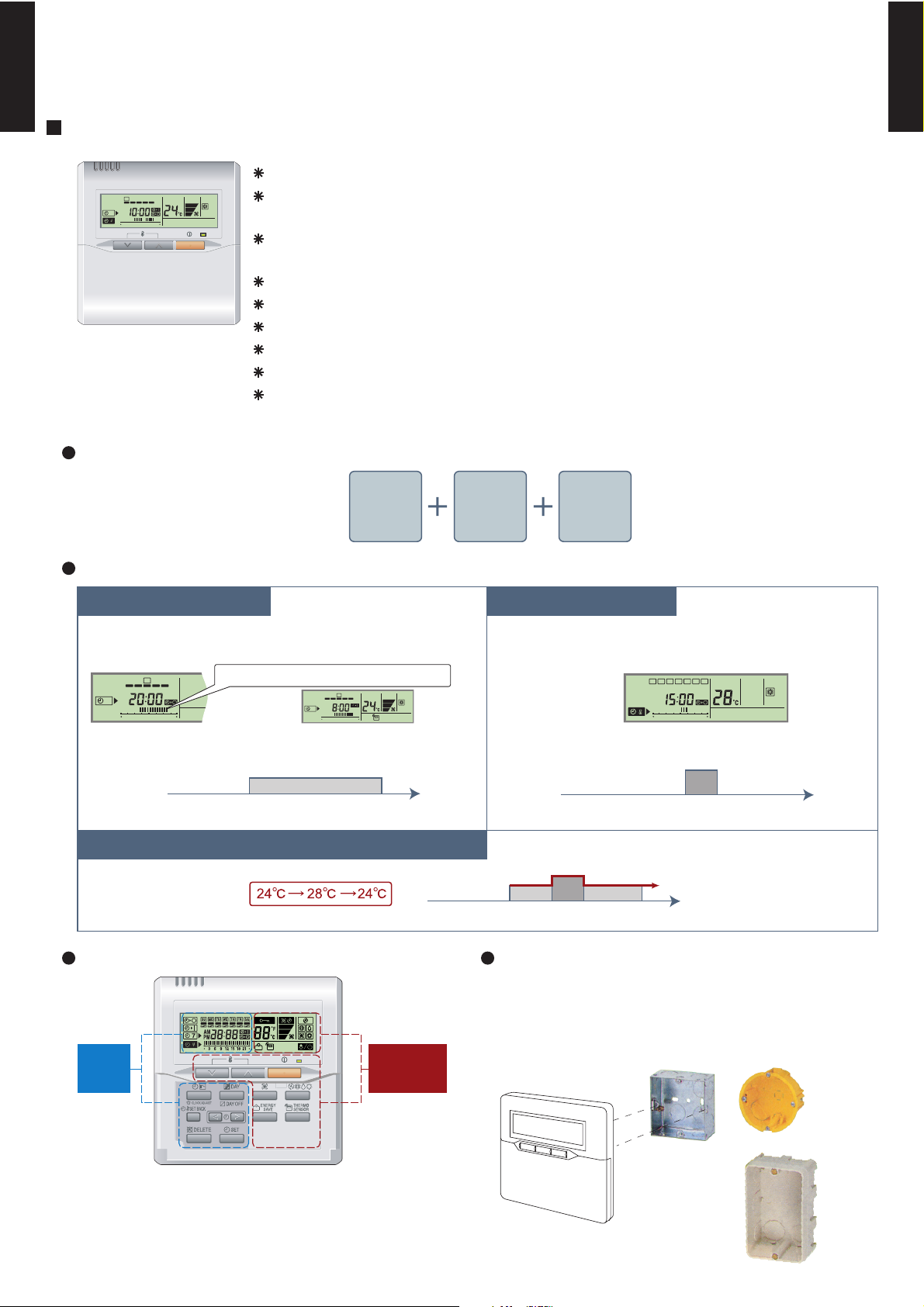
WIRED REMOTE CONTROLLER (FOR DUCT TYPE)
FEATURES
High performance and compact size
Three functions are combined in
SUMOTUWETH FR SA
7
3126 9
15 18 21
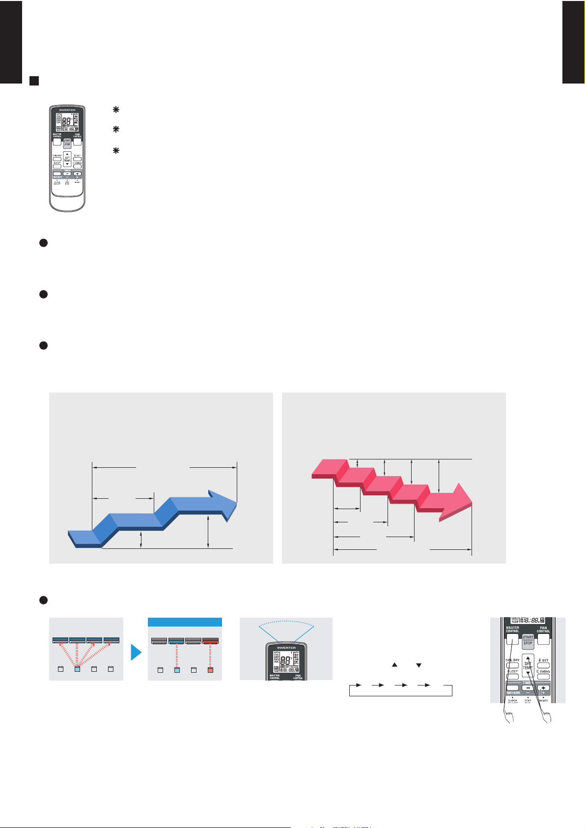
Various timer setup (ON / OFF / WEEKLY) are possible.
Equipped with weekly timer as standard function.
(2 times Start / Stop per day for a week)
When setting up a timer, operation mode and a temperature
setup can be changed.
When a failure occurs,the error code is displayed. (Maximum of 16)
Error indication.(A maximum of 16 error histories are memorizable.)
Up to 16 indoor units can be simultaneously controlled.
Anti freeze and energy saving operation are possible.
Easy installation with a slim shape with no bulge in the back.
The room temperature can be controlled by being detected the temperature
accurately with built-in thermo sensor.
Wired
remote
controller
Weekly
timer
Setback
timer
MULTI TYPE
2ROOM TYPE
Built-in timers
Setback timerWeekly timer
Possible to set ON/OFF time to operate twice each day
of the week.
SUMOTUWETH FR SA
7
3126 9
15 18 21
Setup screen example
(Set to Wednesday: 8:00 to 20:00.)
0 3 6 9 12 15 18 21 Time
Easy-to-understand time bar display
24°C
SUMOTUWETH FR SA
7
3126 9
15 18 21
Screen
after setup
Possible to set temperature for two time spans and
for each day of the week.
Setup screen example
(Set from Sunday to Saturday: 12:00 to 15:00, 28 °C.)
0 3 6 9 12 15 18 21 Time
At "Weekly timer" + "Set back timer" setup
24°C
0 3 6 9 12 15 18 21 Time
28°C
Easy-to-understand operation Simple installation
Components are compatible with standard
switch boxes. Flat back construction allows
equipment to be installed wherever it is
Timer
area
Operation
area
needed.
SUMOTUWETH FR SA
3126 9
15 18 21
28°C
[
Variable timer control
]
The operation/display sections are zoned according to time and operation, enabling variable programming to match application.
- (01 - 04) -
European
switch box
JIS box
Page 6
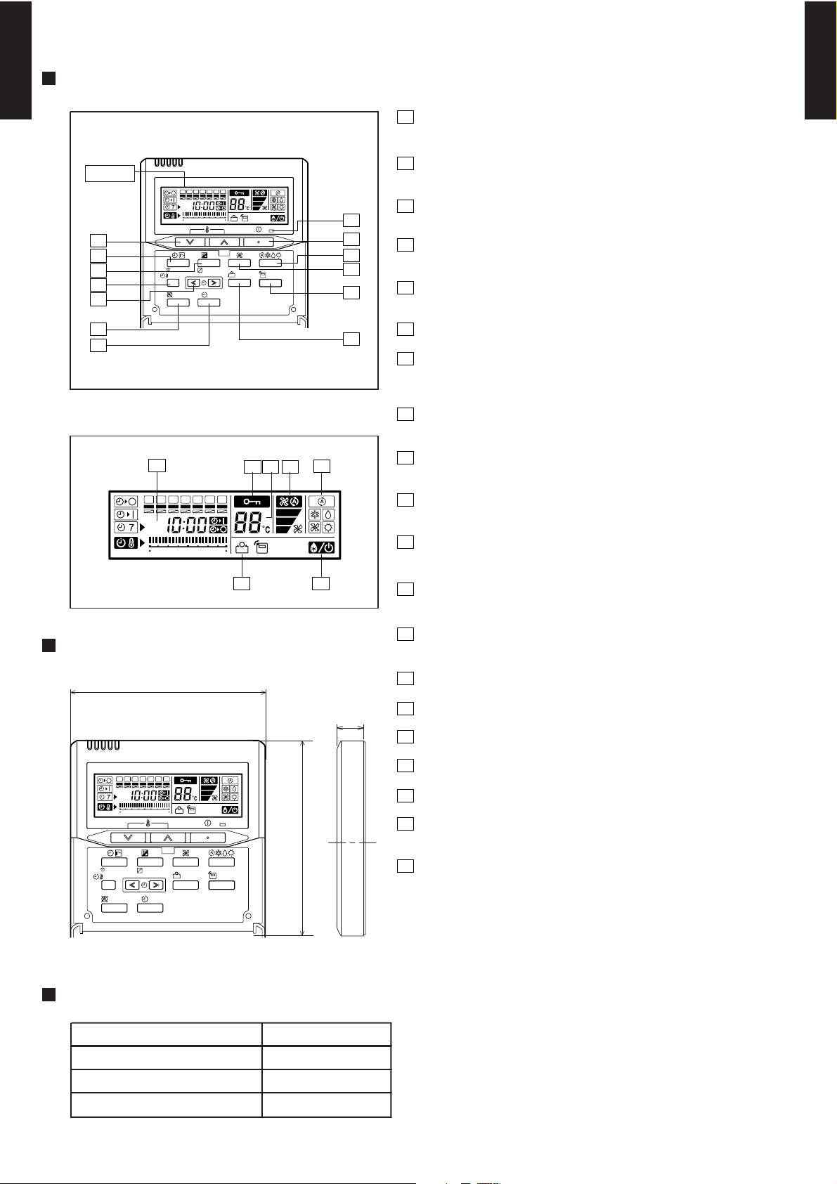
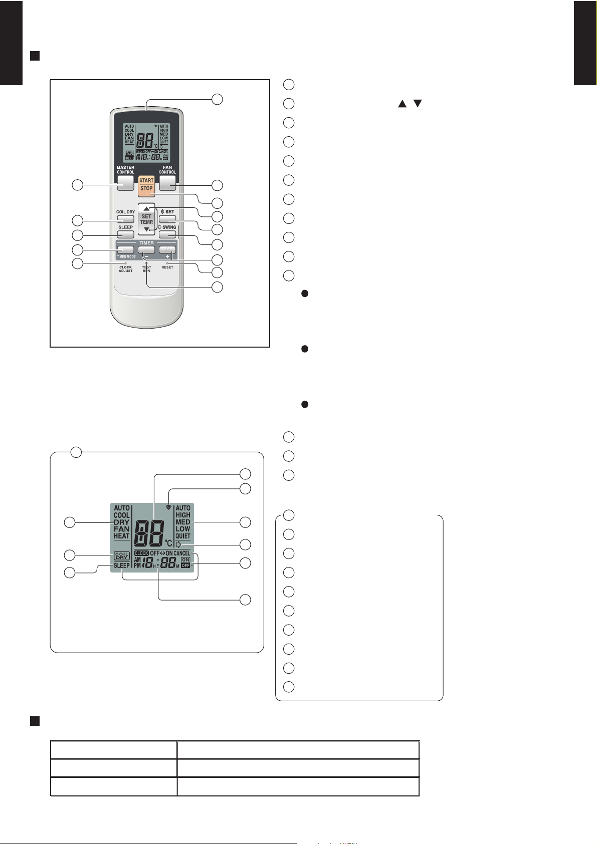
FUNCTIONS
MULTI TYPE
2ROOM TYPE
1
START/STOP button
Pressed to start and stop operation.
2
Display
2
7
8
9
10
SUMOTUWETH FR
369
CLOCK ADJUST
SET BACK
DELETE SET
12 15 18 21
DAY
DAY OFF
SA
13
1
3
ENERGY
SAVE
THERMO
SENSOR
4
6
Set temperature button
Selects the setting temperature.
3
Master control button
Selects the operating mode(AUTO, HEAT, FAN, COOL, DRY).
4
Fan control button
Selects the fan speed (AUTO, LOW, MED, HIGH).
5
Energy save button
Turns the energy efficient mode on and off.
MULTI TYPE
2ROOM TYPE
11
12
Display panel
14
SUMOTUWETH FR
369
DIMENSION
120
12 15 18 21
6
5
Thermo sensor
7
Timer mode (CLOCK ADJUST) button
Selects the timer mode (OFF TIMER, ON TIMER, WEEKLY TIMER)
Set the current time.
8
Day (DAY OFF) button
Temporarily cancels of one day timer.
9
15
1617 18
SA
Set back button
Pressed select the set back timer.
10
Set time button
Pressed to set time.
11
Delete button
The schedule of a weekly timer is deleted.
1920
12
Set button
Sets the date, hour, minute and on-off time.
13
Operation lamp
Lights during operation and when the timer is on.
[ Unit : mm ]
17
14
Timer and clock display
15
Operation mode display
16
Fan speed display
SUMOTUWETH FR
CLOCK ADJUST
SET BACK
DELETE SET
369
12 15 18 21
DAY
DAY OFF
SA
120
ENERGY
THERMO
SAVE
SENSOR
Front View
SPECIFICATION
SIZE (H x W x D mm) 120 x 120 x 17
WEIGHT ( g ) 160
CABLE LENGTH ( m )
POWER ( V )
10
12
17
Central control display
18
Temperature display
19
Stand by display
Indicates during defrosting operation.
20
Energy save display
- (01 - 05) -
Page 7
2-2.
MULTI TYPE
2ROOM TYPE
2-2-1. CASSETTE, CEILING TYPE
WIRELESS REMOTE CONTROLLER
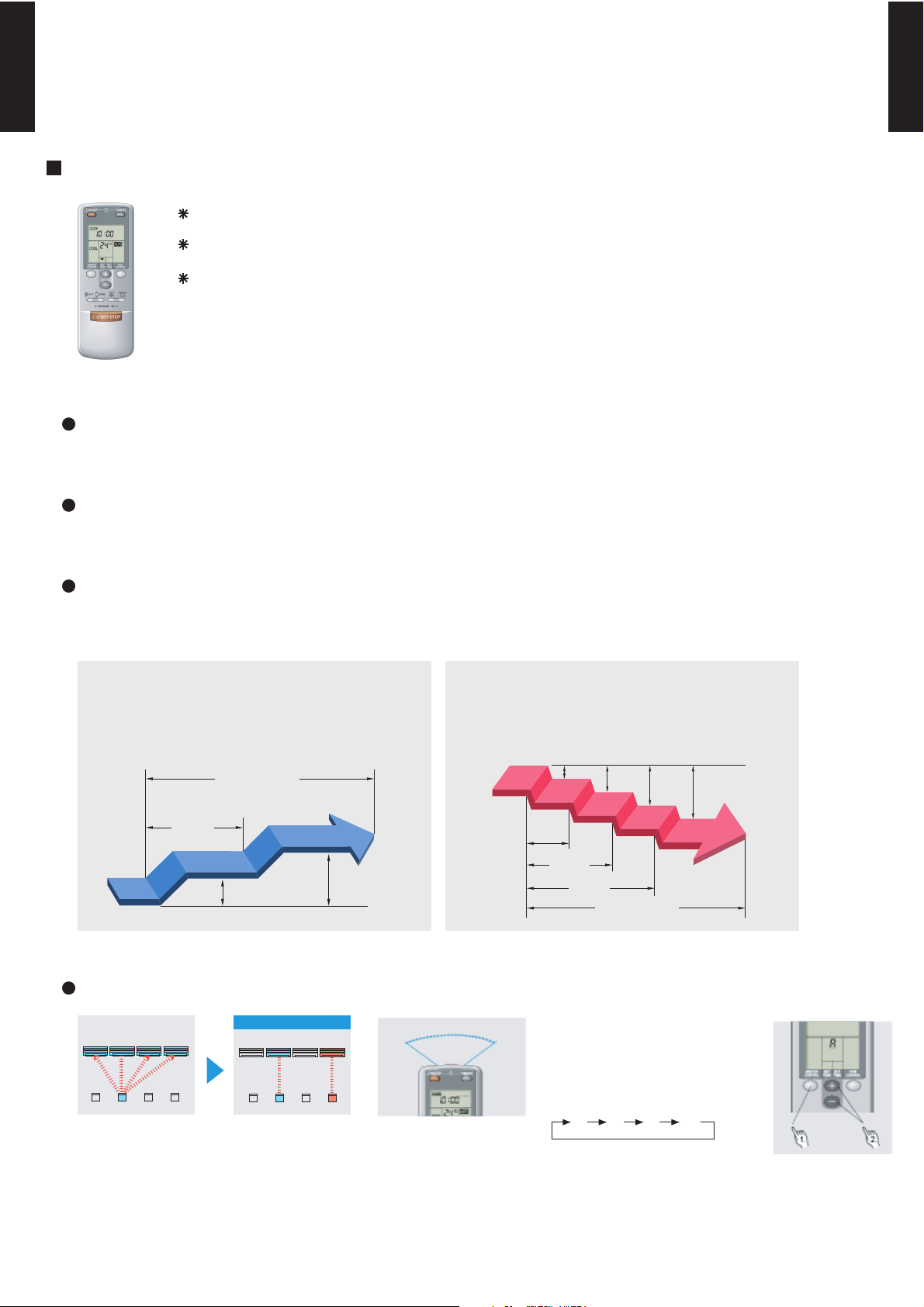
FEATURES
Four kinds of timer setup (ON / OFF / PROGRAM / SLEEP) are possible.
Four kinds of timers. Easy operation.
Easy to change transmission code (4 patterns) by button operation.
Built-in timers
Select from four different timer programs (On/Off/Program/Sleep).
Program timer
The program timer operates the ON and OFF timer once within a 24 hour period.
MULTI TYPE
2ROOM TYPE
Sleep timer
The sleep timer function automatically corrects the temperature thermostat setting according to
the time setting to prevent excessive cooling and heating while sleeping.
Cooling operation/dry operation
When the sleep timer is set, the set temperature
automatically rises 1 °C every hour. The set
temperature can rise up to a maximum of 2 °C.
Timer setting
60min.
1 °C
2 °C
Heating operation
When the sleep timer is set, the set temperature
automatically drops 1 °C every 30 minutes. The
set temperature can drop to a maximum of 4 °C.
1 °C
2 °C
3 °C
4 °C
30min.
60min.
90min.
Timer setting
Easy operation
After code change
Mixed-up
• Code selector switch eliminates unit
being wrongly switched.
(Up to 4 codes can be set.)
A B C D
A B
C
D
•Wide and precise
transmitting range.
1. Press the MASTER CONTROL
button for more than five seconds
to start the code change.
2. Press the (+) or (-) button to
select the desired code.
A B C D
3. Press the MASTER CONTROL
button again to end the code
change.
- (01 - 06) -
Page 8
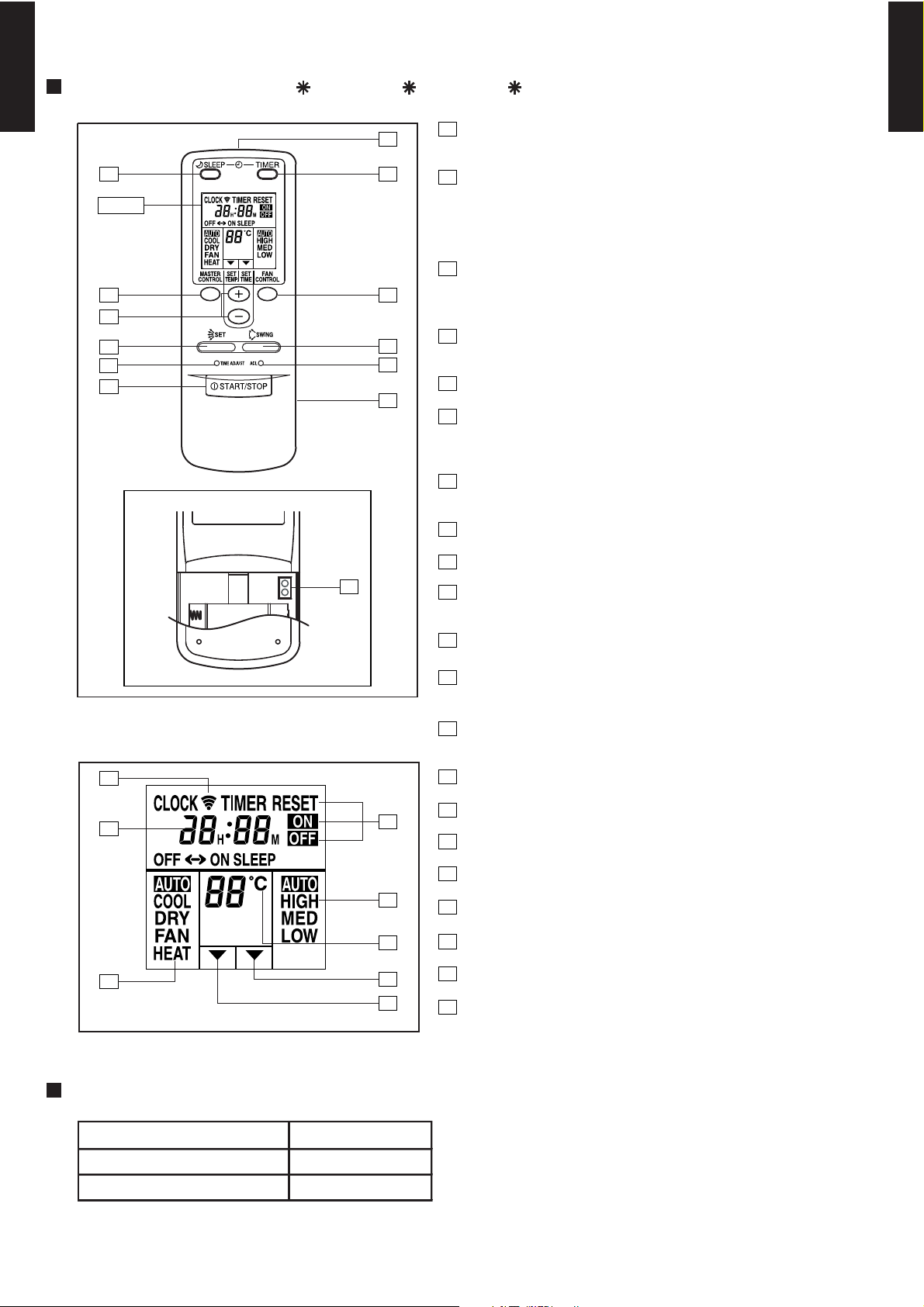
FUNCTIONS (For AU 12L, AU 14L, AU 18L)
MULTI TYPE
2ROOM TYPE
5
1
START/STOP button
Pressed to start and stop operation
MULTI TYPE
2ROOM TYPE
Display
3
2
9
10
1
TEST
RUN
13
11
12
64
2
Set temp./Set time/
Set remote controller custom code buttons
Sets the indoor temp./ Sets the current time and on-off time.
/Sets R.C. custom code.
3
Master control / Code change buttons
7
8
Selects the operating mode (AUTO, HEAT, FAN, COOL, DRY).
/Start / end R.C. custom code change. (Max 4 types)
4
Sleep timer button
Pressed to select sleep timer.
5
Signal transmitter
6
Timer button
Pressed to select the timer mode. (OFF TIMER, ON TIMER,
PROGRAM TIMER, TIMER RESET)
7
Fan control button
Selects the fan speed (AUTO, LOW, MED, HIGH).
8
Battery compartment lid
9
Air flow direction vertical set button
10
Time adjust button
Sets the current time.
Display panel
14
15
16
17
18
19
20
21
11
Air flow direction vertical swing button
12
ACL button
Used when replacing batteries or change the code.
13
Test run button
Used when testing the air conditioner after installation.
14
Transmit indicator
15
Clock display
16
Master control display
17
Timer mode display
18
Fan speed display
19
Set temperature display
20
Timer set indicator
21
Temperature set indicator
SPECIFICATION
SIZE (H x W x D mm) 158 x 56 x 20
WEIGHT ( g )
ACCESSORY Holder
70 (w/o batteries)
- (01 - 07) -
Page 9
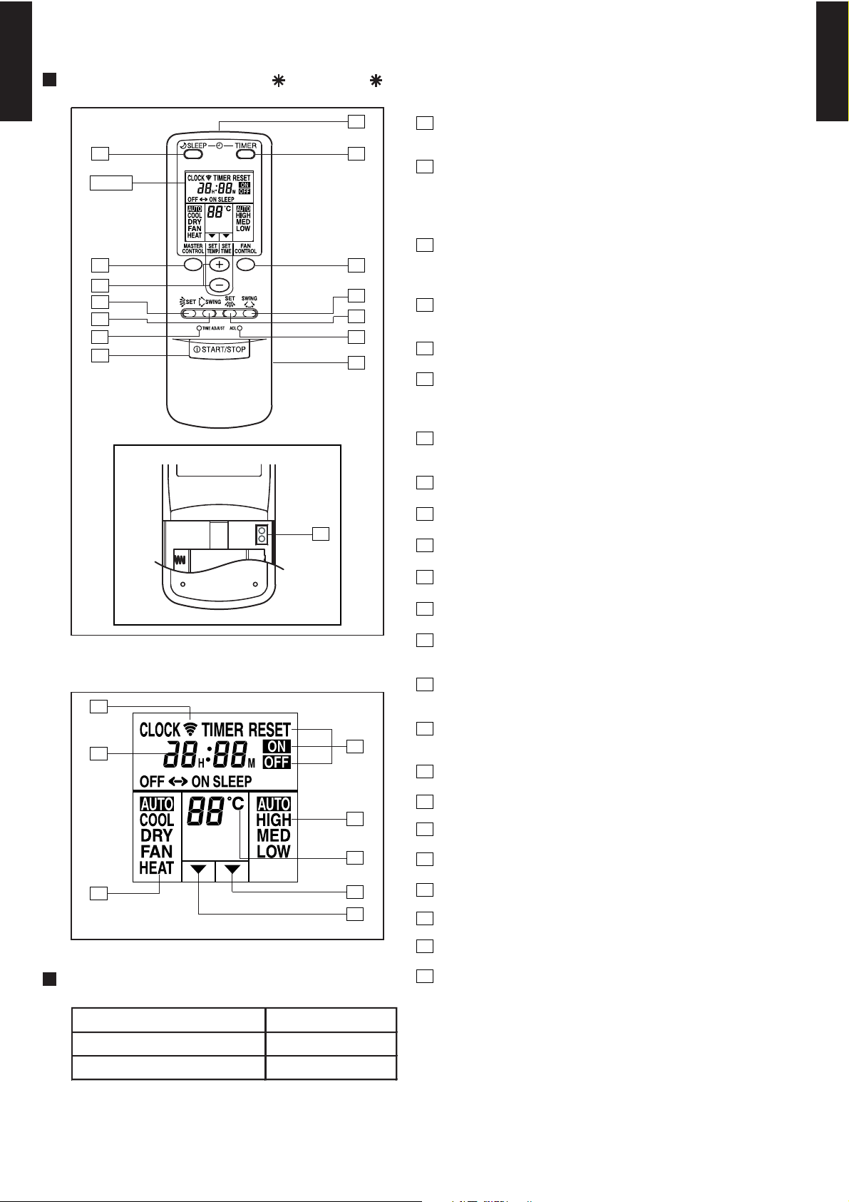
FUNCTIONS (For AB 14L, AB 18L)
MULTI TYPE
2ROOM TYPE
5
1
START/STOP button
Pressed to start and stop operation
64
Display
2
Set temp./Set time buttons/Set remote controller
custom code buttons
Sets the indoor temp./Sets the current time and on-off time
/Set R.C. custom code
3
10
13
Master control button/
3
2
9
1
7
11
12
14
8
Selects the operating mode (AUTO, HEAT, FAN, COOL, DRY).
Start/end R.C. custom code change. (Max. 4 types)
4
Sleep timer button
Pressed to select sleep timer.
5
Signal transmitter
6
Timer button
Code change
Pressed to select the timer mode. (OFF TIMER, ON TIMER,
PROGRAM TIMER, TIMER RESET)
7
Fan control button
Selects the fan speed (AUTO, LOW, MED, HIGH).
8
Battery compartment lid
MULTI TYPE
2ROOM TYPE
Display panel
16
17
18
TEST
RUN
15
19
20
21
22
23
9
Air flow direction vertical set button
10
Air flow direction vertical swing button
11
Air flow direction horizontal swing button
12
Air flow direction horizontal set button
13
Time adjust button
Sets the current time.
14
ACL button
Used when replacing batteries or change the code.
15
Test run button
Used when testing the air conditioner after installation.
16
Transmit indicator
17
Clock display
18
Master control display
19
Timer mode display
20
Fan speed display
21
Set temperature display
SPECIFICATION
SIZE (H x W x D mm) 158 x 56 x 20
WEIGHT ( g )
ACCESSORY Holder
70 (w/o batteries)
22
23
- (01 - 08) -
Timer set indicator
Temperature set indicator
Page 10
2-2-2. WALL MOUNTED TYPE
MULTI TYPE
2ROOM TYPE
FEATURES
Four kinds of timer setup (ON / OFF / PROGRAM / SLEEP) are possible.
Four kinds of timers. Easy operation.
Easy to change transmission code (4 patterns) by button operation.
Built-in timers
Select from four different timer programs (On/Off/Program/Sleep).
Program timer
The program timer operates the ON and OFF timer once within a 24 hour period.
MULTI TYPE
2ROOM TYPE
Sleep timer
The sleep timer function automatically corrects the temperature thermostat setting according to
the time setting to prevent excessive cooling and heating while sleeping.
Cooling operation/dry operation
When the sleep timer is set, the set temperature
automatically rises 1 °C every hour. The set
temperature can rise up to a maximum of 2 °C.
Timer setting
60min.
1 °C
2 °C
Heating operation
When the sleep timer is set, the set temperature
automatically drops 1 °C every 30 minutes. The
set temperature can drop to a maximum of 4 °C.
1 °C
2 °C
3 °C
4 °C
30min.
60min.
90min.
Timer setting
Easy operation
After code change
Mixed-up
• Code selector switch eliminates unit
being wrongly switched.
(Up to 4 codes can be set.)
A B C D
A B
C
D
•Wide and precise
transmitting range.
1. Press the MASTER CONTROL
button for more than five seconds
to start the code change.
2. Press the ( ) or ( ) button to
select the desired code.
A B C D
3. Press the MASTER CONTROL
button again to end the code
change.
1
2
- (01 - 09) -
Page 11
SIZE (H×W×D mm)
170 × 56 × 18
FUNCTIONS
MULTI TYPE
2ROOM TYPE
3
1
12
13
4
10
5
6
2
7
8
14
9
11
1
MASTER CONTROL button
2
SET TEMP. buttons( / )
3
Signal Transmitter
4
TIMER MODE button
5
FAN CONTROL button
6
START/STOP button
7
AIR FLOW DIRECTION Vertical SET button
8
AIR FLOW DIRECTION Vertical SWING button
9
RESET button
10
CLOCK ADJUST button
11
TEST RUN button
Perform a test run only when installing the air
conditioner .If the signal to perform a test run is received
during normal operation, the air conditioner's thermostat
will malfunction.
If the signal to perform a test run is received during
normal operation, the unit will switch to the test
operation mode and the indoor unit's OPERATION and
TIMER indicator lamps will flash simultaneously.
MULTI TYPE
2ROOM TYPE
Display panel
15
18
24
23
21
16
20
22
19
17
To stop the test operation mode, press the
START/STOP button to stop the air conditioner.
12
COIL DRY button
13
SLEEP button
14
SET TIME button(+/-)
15
Remote Control Unit Display
16
Transmit Indicator
17
Clock Display
18
Operating Mode Display
19
Timer Mode Display
20
Fan Speed Display
21
Temperature Set Display
22
SWING Display
23
SLEEP Display
24
COIL DRY Display
SPECIFICATION
WEIGHT
ACCESSORY Holder
(g)
85
(w/o batteries)
- (01 - 10) -
Page 12
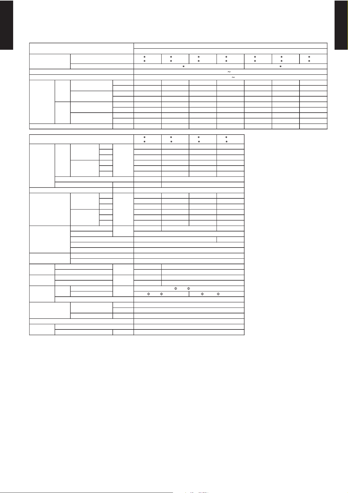
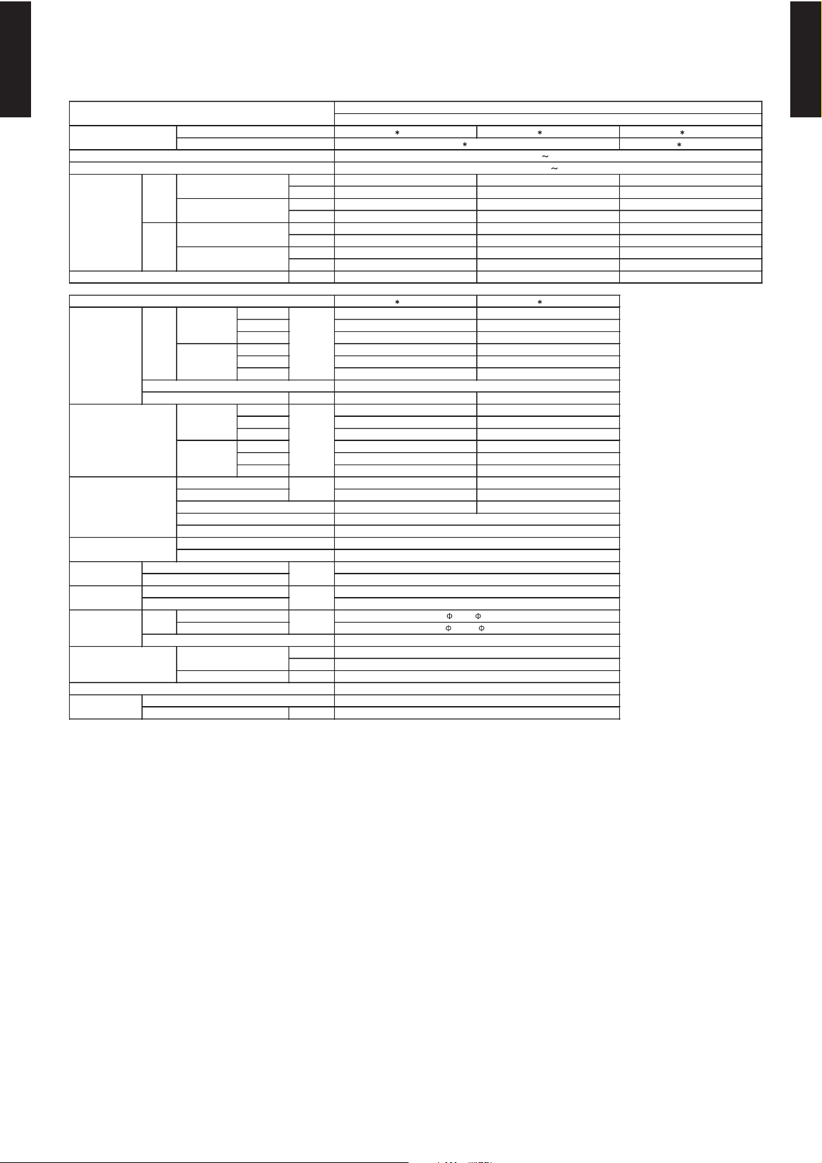
3. SPECIFICATIONS
AR 9LUAB AR 12LUAD AR 14LUAD AR 18LUAD AR 9LUAB AR 12LUAD AR 14LUAD
AR 9LUAB
AR 9LUAP
AR 12LUAD
AR 12LUAL
AR 14LUAD
AR 14LUAL
AR 18LUAD
AR 18LUAL
294 × 410 × 26.6
MULTI SATTELITE SYSTEM MODEL
INVERTER HEATPUMP
324 × 1075 × 686
25 ( 55 )
Aluminium
Galvanized steel sheet
230V 50Hz
198-264V 50Hz
AO 18LMAK2
AO 24LMAM2
mm
29 ( 64 )
kg(lb.)
mm
217 × 953 × 595
6.35 ( 1/ 4 in.)
Weight
Dimensions
( H × W × D )
Remote controller type
Drain pipe
Material
Size
Operation range
Cooling
Connection
pipe
Size
Heat exchanger type
Enclosure
Sound pressure level
Fan
Capacity
Cooling
Heating
Moisture removal
Model name
Cooling
Heating
dB(A)
Cooling
Heating
Airflow
rate
TYPE
mm
Rated
Min.- Max.
Rated
Min.- Max.
Power source
Available voltage range
Model name
m3/h
-
Sirocco × 2
42
0 to 40
2 × 14
1.3
294 × 700 × 26.6
Copper
Outer diameter: 26.0 / Inner diameter: 21.5
ABS
Wired
16 to 30
80 or less
18 to 32
Flare
9.52 ( 3/8 in.)
12.70 ( 1/2 in.)
3-1. DUCT TYPE
MULTI TYPE
2ROOM TYPE
MULTI TYPE
2ROOM TYPE
INDOOR UNIT
OUTDOOR UNIT
BTU/h 8900 11900 14700 18400 8900 11900 14700
BTU/h 6100 - 9600 6100 - 13300 6100 - 16700 6800 - 20500 6100 - 9600 6100 - 13300 6100 - 16700
BTU/h 10900 13700 16700 20500 10900 13700 16700
BTU/h 6100 - 13000 6100 - 15700 6100 - 20500 6800 - 25600 6100 - 13000 6100 - 15700 6100 - 20500
l/h (pints/h) 1.0 ( 2.1 ) 1.2 ( 2.5 ) 1.5 ( 3.2 ) 1.7 ( 3.6 ) 1.0 ( 2.1 ) 1.2 ( 2.5 ) 1.5 ( 3.2 )
High 450 600 800 800
Med 410 500 620 640
Low 370 430 480 500
High 450 580 780 800
Med 410 500 620 640
Low 370 430 480 500
Type × Q'ty Sirocco × 1
Motor output W 13
Recommended static pressure Pa
High 39 33 40 41
Med 37 30 35 35
Low 34 27 30 30
High 39 33 40 41
Med 37 30 35 35
Low 34 27 30 30
Dimensions (H × W × D)
Fin pitch
Rows x Stages 3 × 14
Pipe type
Fin type
Material
Colour
Net 217 × 663 × 595
Gross 324 × 785 × 686
Net 18 ( 40 )
Gross 22 ( 48 )
Liquid
Gas
Method
%RH
Heating °C
AR 9LUAP AR 12LUAL AR 14LUAL AR 18LUAL AR 9LUAP AR 12LUAL AR 14LUAL
kW 2.6 3.5 4.3 5.4 2.6 3.5 4.3
kW 1.8 - 2.8 1.8 - 3.9 1.8 - 4.9 2.0 - 6.0 1.8 - 2.8 1.8 - 3.9 1.8 - 4.9
kW 3.1 4.0 4.9 6.0 3.1 4.0 4.9
kW 1.8 - 3.8 1.8 - 4.6 1.8 - 6.0 2.0 - 7.5 1.8 - 3.8 1.8 - 4.6 1.8 - 6.0
294 × 700 × 39.9
°C
Note :
Specifications are based on the following conditions.
Cooling : Indoor temperature of 27 °CDB / 19 °CW B.and outdoor temperature of 35 °CDB/24 °CWB.
Heating : Indoor temperature of 20 °CDB / 15 °CW B.and outdoor temperature of 7 °CDB/6 °CWB.
Standard static pressure : 0Pa
Pipe length : 7.5 m, Height difference : 0 m.(Outdoor unit - Indoor unit)
mm
- (01 - 11) -
Page 13
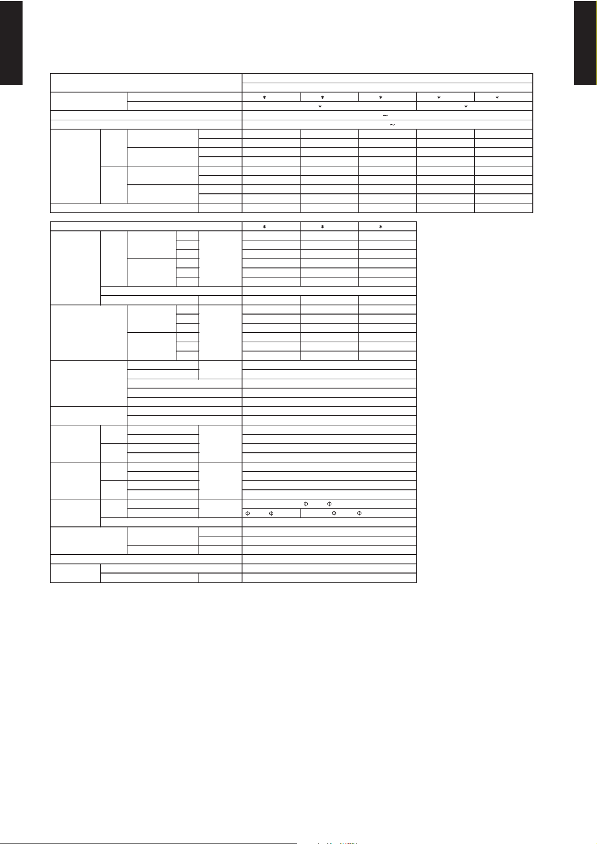
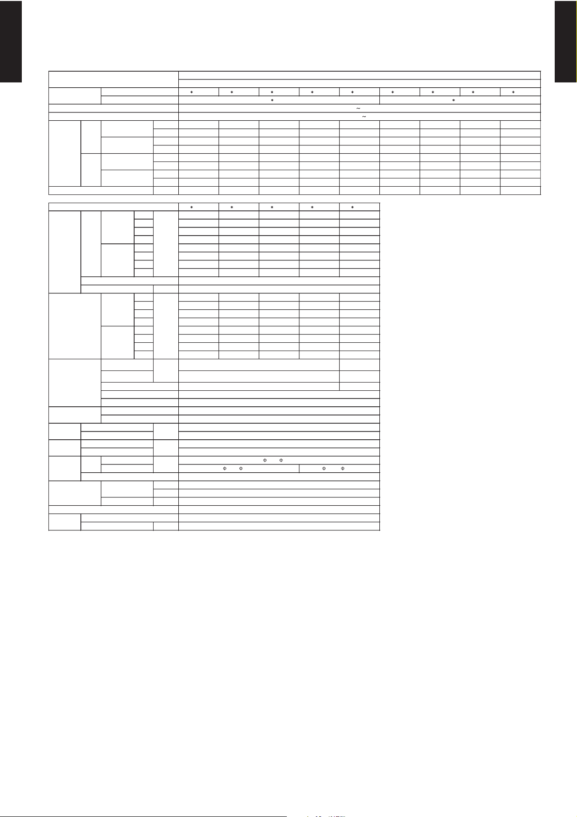
3-2. CASSETTE TYPE
AU 12LBAB AU 14LBAB AU 18LBAB AU 12LBAB AU 14LBAB
70 × 720 × 720
MULTI SATTELITE SYSTEM MODEL
INVERTER HEATPUMP
AO 24LMAM2
AO 18LMAK2
35 × 650 × 650
Aluminium
2 × 10
Copper
198-264V 50Hz
Flare
kg(lb.)mmmm
12.70 ( 1 / 2 in.)
18 ( 40 )
2.2 ( 4.9 )
6.35 ( 1 / 4 in.)
280 × 710 × 750
23 ( 51 )
4.3 ( 9.6 )
Moisture removal
Cooling
Model name
ABS
White(5Y9/0.5NN)
235 × 580 × 580
Enclosure(Panel)
Sound pressure level
TYPE
Power source
Model name
Available voltage range
INDOOR UNIT
OUTDOOR UNIT
m3/h
Fan
Airflow
rate
Capacity
Cooling
Heating
Rated
Min.- Max.
Rated
Min.- Max.
dB(A)
mm
Cooling
Heating
Dimensions (H × W × D)
Connection pipe
Size
Heat exchanger type
Heating
Dimensions
( H × W × D )
Net
Gross
Weight
Net
Gross
Operation range
Remote controller type
Drain pipe
Material
Size
Cooling
PP
Outer diameter: 37.0 / Inner diameter: 32.0
18 to 32
80 or less
16 to 30
Wireless
Turbo × 1
210 × 1000 × 26.6
1.4
230V 50Hz
MULTI TYPE
2ROOM TYPE
kW 3.3 4.0 4.5 3.3 4.0
BTU/h 11300 13700 15400 11300 13700
kW 1.8 - 3.7 1.8 - 4.5 2.0 - 4.7 1.8 - 3.7 1.8 - 4.5
BTU/h 6100 - 12600 6100 - 15400 6800 - 16000 6100 - 12600 6100 - 15400
kW 3.7 4.3 5.5 3.7 4.3
BTU/h 12600 14700 18800 12600 14700
kW 1.8 - 4.4 1.8 - 5.3 2.0 - 6.0 1.8 - 4.4 1.8 - 5.3
BTU/h 6100 - 15000 6100 - 18100 6800 - 20500 6100 - 15000 6100 - 18100
l/h (pints/h) 1.3 ( 2.7 ) 1.5 ( 3.2 ) 2.0 ( 4.3 ) 1.3 ( 2.7 ) 1.5 ( 3.2 )
MULTI TYPE
2ROOM TYPE
High 550 550 620
Med 500 500 520
Low 440 440 450
High 550 550 620
Med 500 500 520
Low 440 440 450
Type × Q'ty
Motor output W 10 10 14
High 42 42 44
Med 39 39 41
Low 36 36 38
High 42 42 44
Med 39 39 41
Low 36 36 38
Fin Pitch
Rows x Stages
Pipe type
Fin type
Material
Colour
Unit
Panel
Unit
Panel
Unit
Panel
Unit
Panel
Liquid
Gas 9.52 ( 3 / 8 in.)
Method
°C
%RH
Heating °C
AU 12LBAB AU 14LBAB AU 18LBAB
Note :
Specifications are based on the following conditions.
Cooling : Indoor temperature of 27 °CDB / 19 °CW B.and outdoor temperature of 35 °CDB/24 °CWB.
Heating : Indoor temperature of 20 °CDB / 15 °CW B.and outdoor temperature of 7 °CDB/6 °CWB.
Pipe length : 7.5 m, Height difference : 0 m.(Outdoor unit - Indoor unit)
mm
- (01 - 12) -
Page 14
3-3. CEILING (UNIVERSAL) TYPE
AB 14LBAJ AB 18LBAJ AB 14LBAJ
AO 18LMAK2
AB 14LBAJ AB 18LBAJ
Dimensions (H × W × D)
INDOOR UNIT
OUTDOOR UNIT
Fin type
Drain pipe
Material
Size
Operation range
Cooling
Heating
Remote controller type
kg(lb.)
Connection pipe
Size
mm
Weight
Model name
Available voltage range
Dimensions
(H × W × D)
mm
Airflow
rate
Heat exchanger type
Enclosure
Sound pressure level
Cooling
Heating
Min.- Max.
Moisture removal
Cooling
m3/h
Fan
Model name
Capacity
Cooling
Heating
Sirocco × 2
Copper
Aluminium
mm
dB(A)
ABS
White(5Y9/0.5NN)
199 × 990 × 655
320 × 1150 × 790
28 ( 62 )
37 ( 82 )
6.35 ( 1/4 in.)
12.70 ( 1/2 in.)
Wireless
Outer diameter: 29.0 / Inner diameter: 25.0
PVC
Flare
18 to32
80 or less
16 to 30
Rated
Min.- Max.
Rated
MULTI SATTELITE SYSTEM MODEL
INVERTER HEATPUMP
230V 50Hz
198-264V 50Hz
AO 24LMAM2
TYPE
Power source
MULTI TYPE
2ROOM TYPE
kW 4.2 5.0 4.2
BTU/h 14300 17100 14300
kW 1.8 - 4.9 2.0 - 5.7 1.8 - 4.9
BTU/h 6100 - 16700 6800 - 19500 6100 - 16700
kW 4.8 6.1 4.8
BTU/h 16400 20800 16400
kW 1.8 - 6.0 2.0 - 7.4 1.8 - 6.0
BTU/h 6100 - 20500 6800 - 25300 6100 - 20500
l/h (pints/h) 1.5 ( 3.2 ) 1.7 ( 3.6 ) 1.5 ( 3.2 )
High 640 780
Med 560 650
Low 480 550
High 640 780
Med 560 650
Type × Q'ty
Motor output W 16 30
Fin Pitch 1.2 1.3
Rows x Stages 2 × 12 3 × 12
Pipe type
Low 480 550
High 37(Floor console) ,36 (Under ceiling) 44(Floor console) , 43(Under ceiling)
Med 34(Floor console) ,33 (Under ceiling) 41(Floor console) , 40(Under ceiling)
Low 30(Floor console) , 29(Under ceiling) 36(Floor console) , 35(Under ceiling)
High 37(Floor console) , 36(Under ceiling) 44(Floor console) , 43(Under ceiling)
Med 34(Floor console) , 33(Under ceiling) 41(Floor console) , 40(Under ceiling)
Low 30(Floor console) , 29(Under ceiling) 36(Floor console) ,35 (Under ceiling)
294 × 800 × 26.6 294 × 700 × 39.9
MULTI TYPE
2ROOM TYPE
Material
Colour
Net
Gross
Net
Gross
Liquid
Gas
Method
Heating °C
Note :
Specifications are based on the following conditions.
Cooling : Indoor temperature of 27 °CDB / 19 °CW B.and outdoor temperature of 35 °CDB/24 °CWB.
Heating : Indoor temperature of 20 °CDB / 15 °CW B.and outdoor temperature of 7 °CDB/6 °CWB.
Pipe length : 7.5 m, Height difference : 0 m.(Outd oor unit - Indoor unit)
°C
%RH
mm
- (01 - 13) -
Page 15
3-4. WALL MOUNTED TYPE
336 × 855 × 26.6
84 × 63 × 13.3
1.2 (2ROW)
1.4 (2ROW)
Cooling
Heating
Size
Model name
Type × Q'ty
Dimensions (H × W × D)
Net
Gross
Net
Gross
Moisture removal
Fin pitch
Rows × Stages
Pipe type
AO 18LMAK2
INVERTER HEATPUMP
MULTI SATTELITE SYSTEM MODEL
Aluminium
AO 24LMAM2
198 - 264V 50Hz
230V 50Hz
Cross flow fan × 1
42
Wireless
9 (20)
12 (26.4)
275 × 790 × 215
290 × 835 × 360
16 to 30
80 or less
9.52 ( 3/8in.)
18 to 32
12.70 ( 1/2in.)
HIPS
Cooling
Heating
Dimensions
(H × W × D )
Copper tube
1.2
2 × 16
Fin type
Material
Colour
Remote controller type
Drain pipe
Material
Operation range
kg(lb.)
Connection
pipe
Size
mm
Weight
Liquid
Gas
Method
Airflow
rate
Heat exchanger type
Enclosure
Sound pressure level
Model name
Capacity
Cooling
Rated
Min.- Max.
Rated
Min.- Max.
INDOOR UNIT
OUTDOOR UNIT
Flare
TYPE
Cooling
m3/h
Fan
Power source
Available voltage range
Heating
mm
Outer diameter : 16.7 / Inner diameter : 14.7
Heating
White (5Y9/0.5NN)
6.35 ( 1/4in.)
336 × 635 × 26.6
PE
dB(A)
mm
MULTI TYPE
2ROOM TYPE
AS A07LACM AS A09LACM AS A12LACM AS A14LACM AS A18LACM AS A07LACM AS A09LACM AS A12LACM AS A14LACM
kW 2.3 2.7 3.5 4.2 5.2 2.3 2.7 3.5 4.2
BTU/h 7900 9200 11900 14300 17100 7900 9200 11900 14300
kW 1.8 - 2.7 1.8 - 3.2 1.8 - 4.0 1.8 - 4.8 2.0 - 5.6 1.8 - 2.7 1.8 - 3.2 1.8 - 3.7 1.8 - 4.8
BTU/h 6100 - 9200 6100 - 10900 6100 - 13700 6100 - 16400 6800 - 19100 6100 - 9200 6100 - 10900 6100 - 12600 6100 - 16400
kW 2.7 3.3 4.0 4.8 6.0 2.7 3.3 4.0 4.8
BTU/h 9200 11300 13700 16400 2050 0 9200 11300 13700 16400
kW 1.8 - 3.3 1.8 - 4.0 1.8 - 4.8 1.8 - 6.0 2.0 - 7.1 1.8 - 3.3 1.8 - 4.2 1.8 - 4.8 1.8 - 5.8
BTU/h 6100 - 11300 6100 - 1370 0 6100 - 16400 6100 - 20500 6800 - 24200 6100 - 11300 6100 - 1430 0 6100 - 16400 6100 - 19800
l/h (pints/h) 0.8 (1.7) 1.0 (2.1) 1.2 (2.5) 1.4 (3.0) 2.0 (4.2) 0.8 (1.7) 1.0 (2.1) 1.2 (2.5) 1.4 (3.0)
High 500 550 580 700 660
Med 430 460 480 580 540
Low 370 380 380 470 470
Quiet 270 280 300 360 390
High 500 550 600 700 660
Med 460 490 530 580 540
Low 420 450 470 500 470
Quiet 320 340 360 420 390
Motor output W
High 35 38 39 45 45
Med 32 33 34 38 38
Low 27 28 28 33 34
Quiet 21 22 23 26 28
High 35 37 39 45 45
Med 32 33 34 38 38
Low 29 30 31 34 34
Quiet 22 23 24 28 28
AS A07LACM AS A09LACM AS A12LACM AS A14LACM AS A18LACM
MULTI TYPE
2ROOM TYPE
°C
%RH
°C
mm
Note :
Specifications are based on the following conditions.
Cooling : Indoor temperature of 27°CDB/19°CWB. a nd outdoor temperature of 35°CDB/24°CWB.
Heating : Indoor temperature of 20°CDB/15°CWB. and outdoor temperature of 7°CDB/6°CWB.
Pipe length : 7.5 m, Height difference : 0 m. (Outdoor unit - Ind oor unit)
2 × 16 + 1 × 4
- (01 - 14) -
Page 16
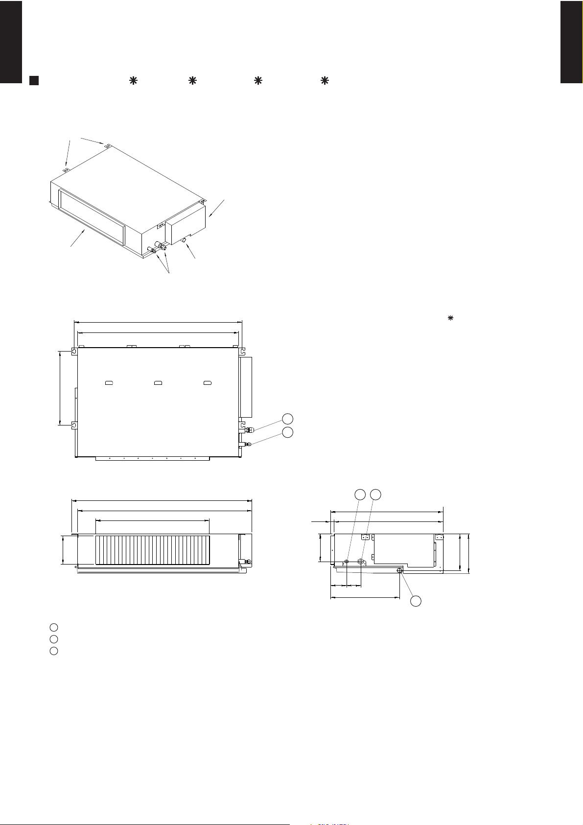
4. DIMENSIONS
4-1. DUCT TYPE
MULTI TYPE
2ROOM TYPE
MODEL : AR 9L, AR 12L, AR 14L, AR 18L
BRACKETS
AIR FLOW OUTLET
DRAIN PORT
COUPLING PIPE ASSY
CONTROL BOX
(Unit : mm)
MULTI TYPE
2ROOM TYPE
886(596)
850(560)
390
( ) : AR 9L
1
2
Top view
953(663)
920(630)
600(400)
150
Front view
150
85 75
12
595
57520
364
Side view
194
217
3
1
Refrigerant piping flare connection (Gas)
2
Refrigerant piping flare connection (Liquid)
3
Drain piping connection
- (01 - 15) -
Page 17
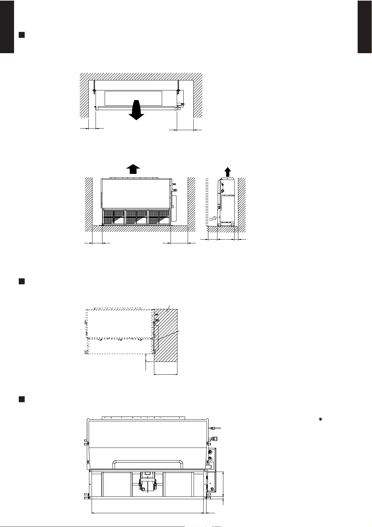
MOUNTING POSITION
MULTI TYPE
2ROOM TYPE
Strong and durable ceiling
Indoor unit
(Unit : mm)
MULTI TYPE
2ROOM TYPE
Left
side
100 or more
Left
side
Strong and durable floor
100 or more 300 or more
Right
side
300 or more
Right side
(PIPE side)
30
or more30or more
MAINTENANCE HOLE
Unit
100
or more
BOTTOM AIR INTAKE HOLE
(Unit : mm)
Maintenance hole
Control box
300
or more
(Unit : mm)
( ) : AR 9L
811(531) 20(15)
- (01 - 16) -
18 177
Page 18
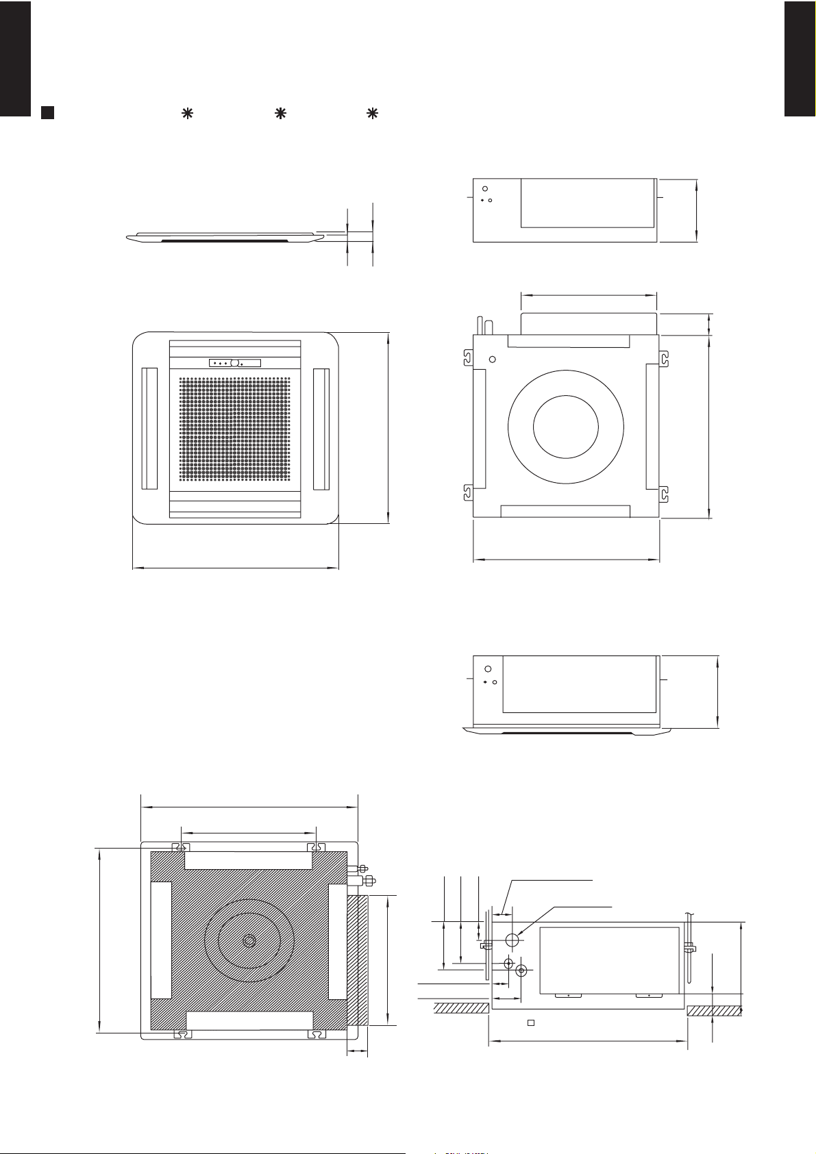
4-2. CASSETTE TYPE
MULTI TYPE
2ROOM TYPE
MODEL : AU 12L, AU 14L, AU 18L
(Unit : mm)
MULTI TYPE
2ROOM TYPE
650
Bottom view (Panel)
20
35
440
650
580
235
66
580
Bottom view
245
Side view
(Grille measurement)
650
(Hanging bolt position)
400
60
600
Drain pipe
245
54
47
111
131
440
(Hanging bolt position)
606
Top view
66
46
86
(Ceiling opening measurement)
- (01 - 17) -
Page 19
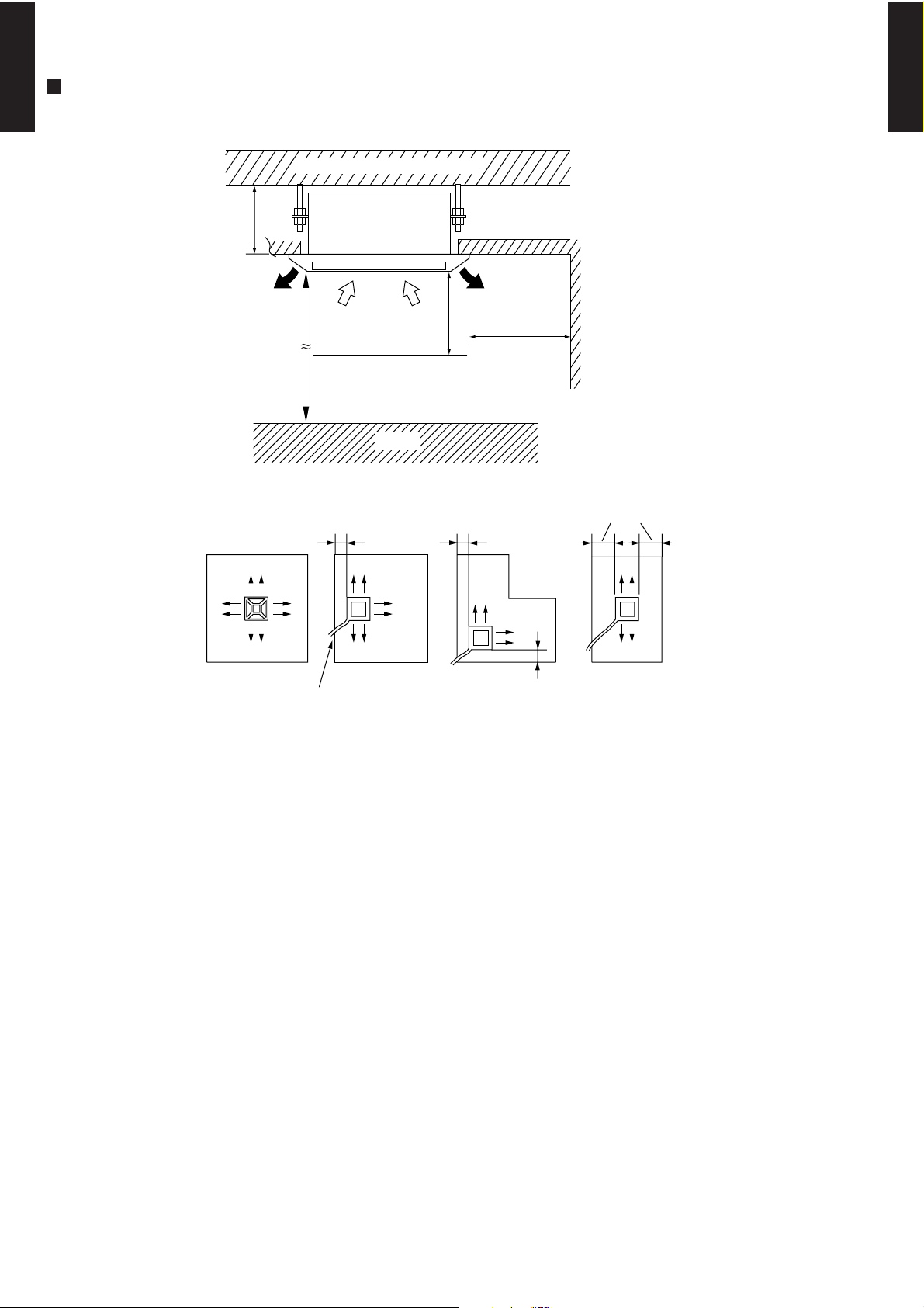
MOUNTING POSITION
Floor
MULTI TYPE
2ROOM TYPE
(Unit : mm)
Strong and durable ceiling
250 or more
MULTI TYPE
2ROOM TYPE
1,000 or more
2,300
or more
(4 directions) (3 directions)
Piping position
Obstruction
100 or more 100 or more
1,000
or more
100 or more
(2 directions) (2 directions)
100 or more
- (01 - 18) -
Page 20
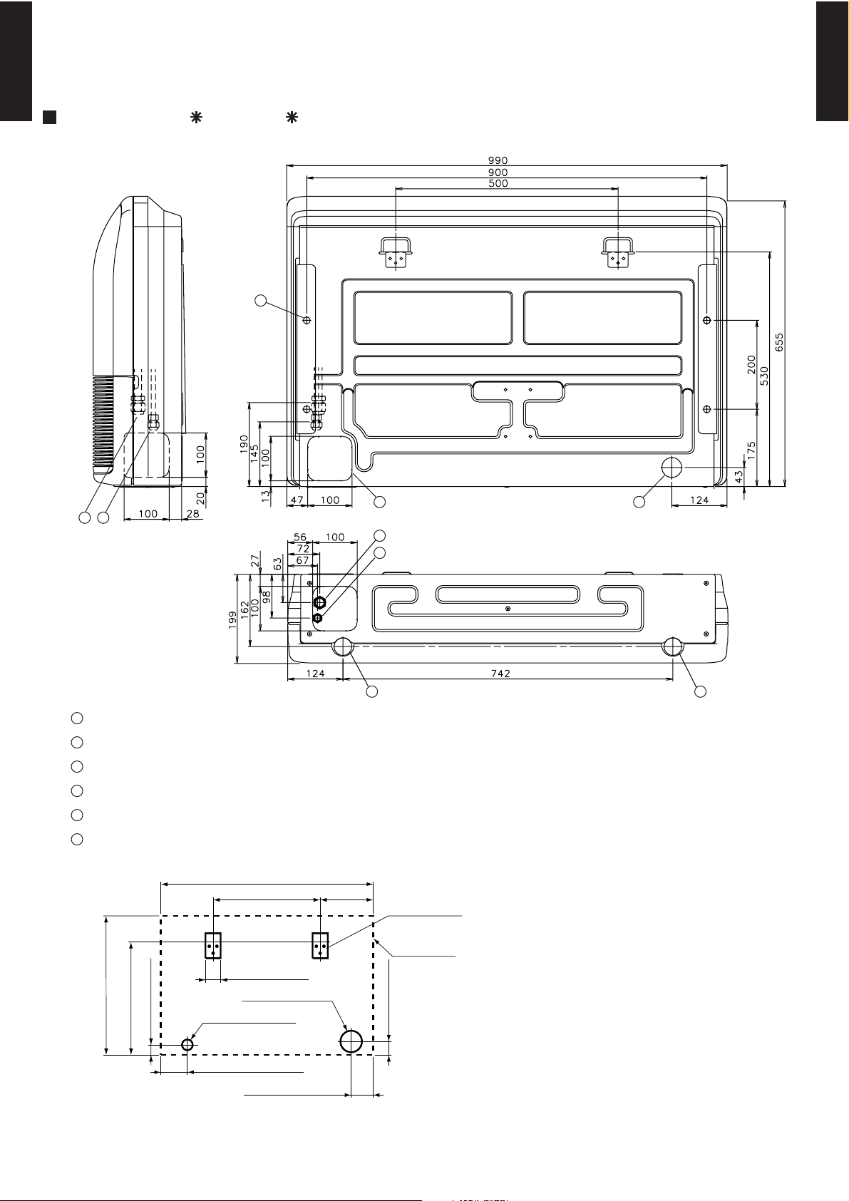
4-3. CEILING (UNIVERSAL) TYPE
MULTI TYPE
2ROOM TYPE
MODEL : AB 14L, AB 18L
6
(Unit : mm)
MULTI TYPE
2ROOM TYPE
1 2
Side view
1
Refrigerant piping flare connection (Gas)
2
Refrigerant piping flare connection (Liquid)
3
Drain piping connection
4
Knock out hole for drain piping
5
Knock out hole for refrigerant piping
6
Hole for lifting bolt (Use M10 screw bolt)
990
500 245
1
2
3
Wall bracket
Rear view
Bottom view
45
3
Side of set
65
655
530
45
125
100 hole
50 hole
65
100 hole
- (01 - 19) -
Page 21
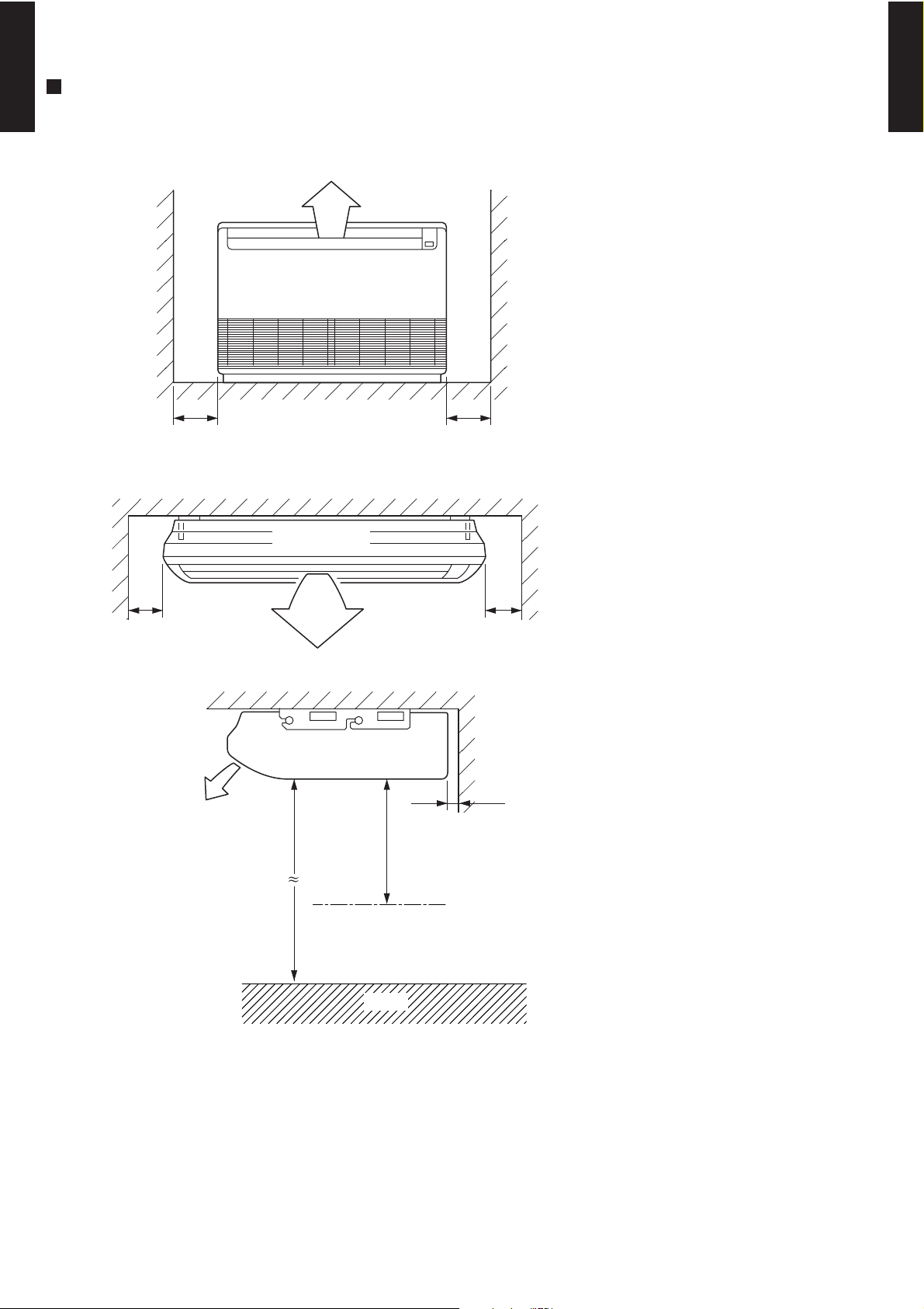
MOUNTING POSITION
Floor
MULTI TYPE
2ROOM TYPE
(Unit : mm)
Left Right
300 or more300 or more
Ceiling
MULTI TYPE
2ROOM TYPE
Left
150 or more 300 or more
Indoor unit
Ceiling
2300 or more
20 or more
1000 or more
Obstruction
Right
- (01 - 20) -
Page 22
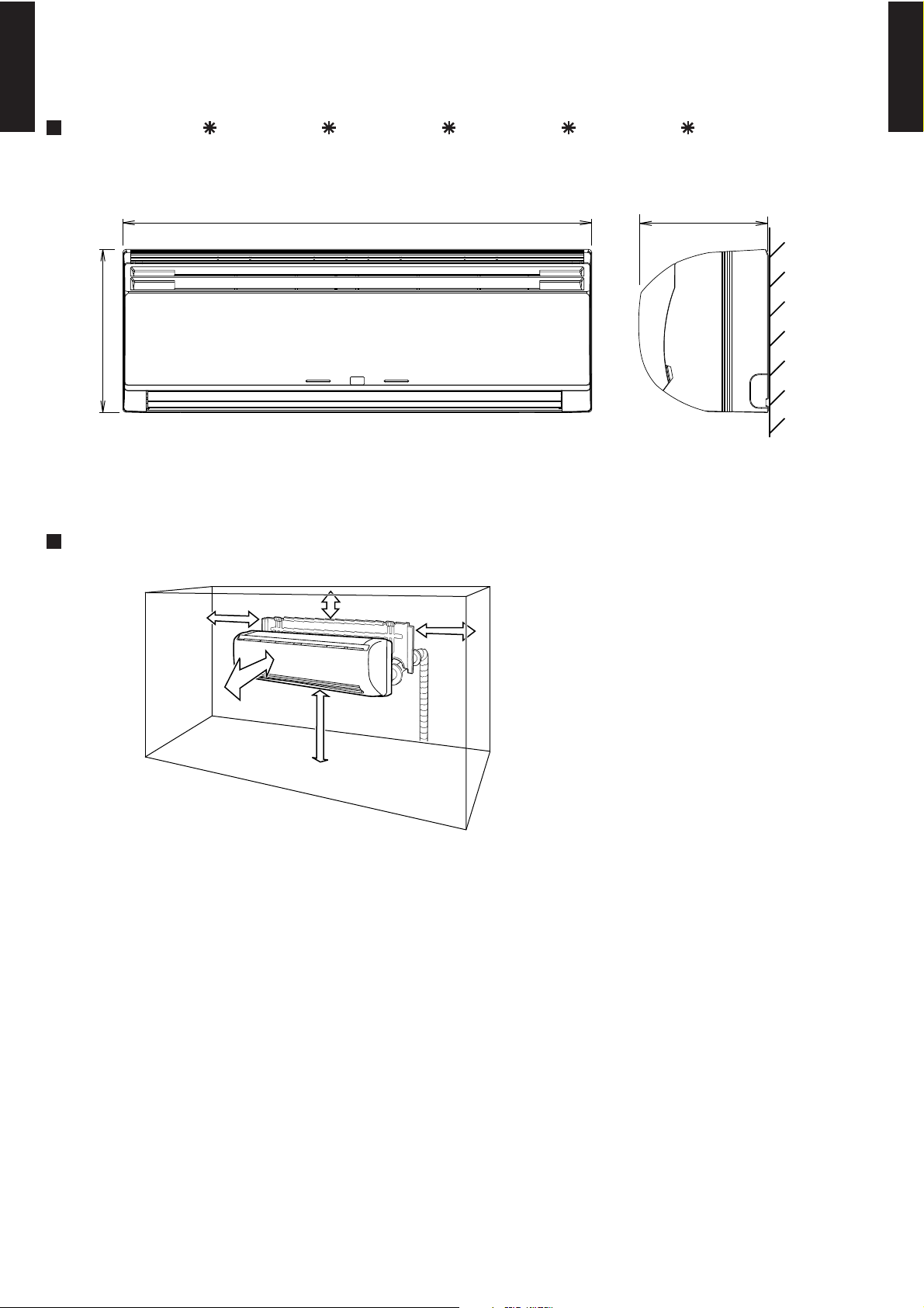
4-4. WALL MOUNTED TYPE
MULTI TYPE
2ROOM TYPE
MODEL : AS A07L, AS A09L, AS A12L, AS A14L, AS A18L
275
(Unit : mm)
215790
Front view Side view
MULTI TYPE
2ROOM TYPE
MOUNTING POSITION
Left side
60 or over
1500 or over
(Unit : mm)
50 or over
Right side
90 or over
2300 or over
- (01 - 21) -
Page 23
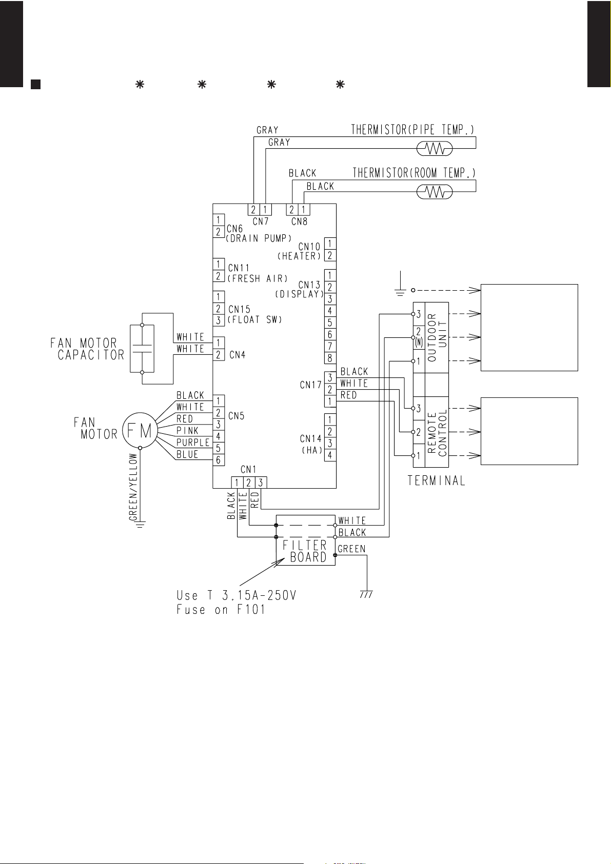
5. WIRING DIAGRAMS
5-1. DUCT TYPE
MULTI TYPE
2ROOM TYPE
MODEL : AR 9L, AR 12L, AR 14L, AR 18L
TO OUTDOOR
UNIT
MULTI TYPE
2ROOM TYPE
CONTROL
BOARD
TO REMOTE
CONTROL UNIT
- (01 - 22) -
Page 24
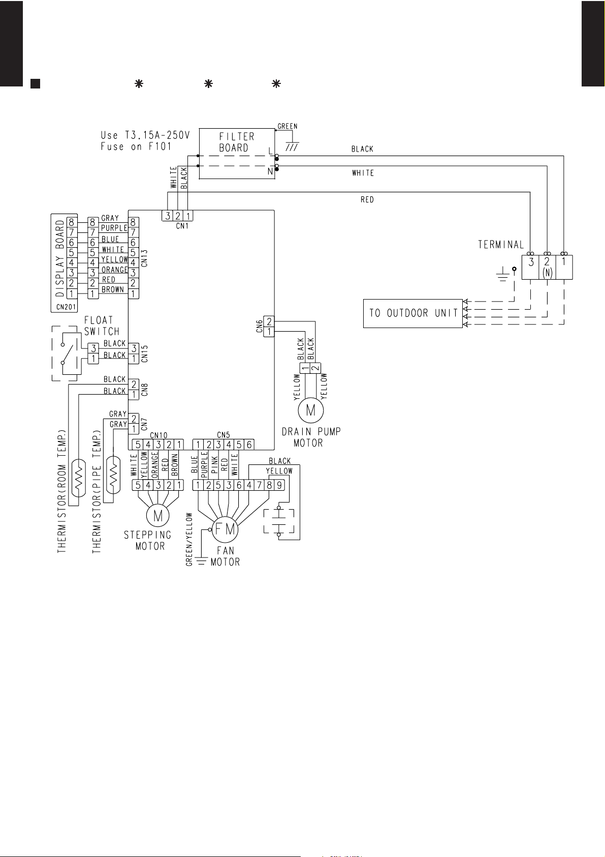
5-2. CASSETTE TYPE
MULTI TYPE
2ROOM TYPE
MODEL : AU 12L, AU 14L, AU 18L
CONTROL
BOARD
MULTI TYPE
2ROOM TYPE
FAN MOTOR
CAPACITOR
- (01 - 23) -
Page 25
5-3. CEILING (UNIVERSAL) TYPE
MULTI TYPE
2ROOM TYPE
MODEL : AB 14L, AB 18L
CONTROL
BOARD
MULTI TYPE
2ROOM TYPE
TO OUTDOOR UNIT
Use T3.15A 250V
FUSE on F101
- (01 - 24) -
Page 26
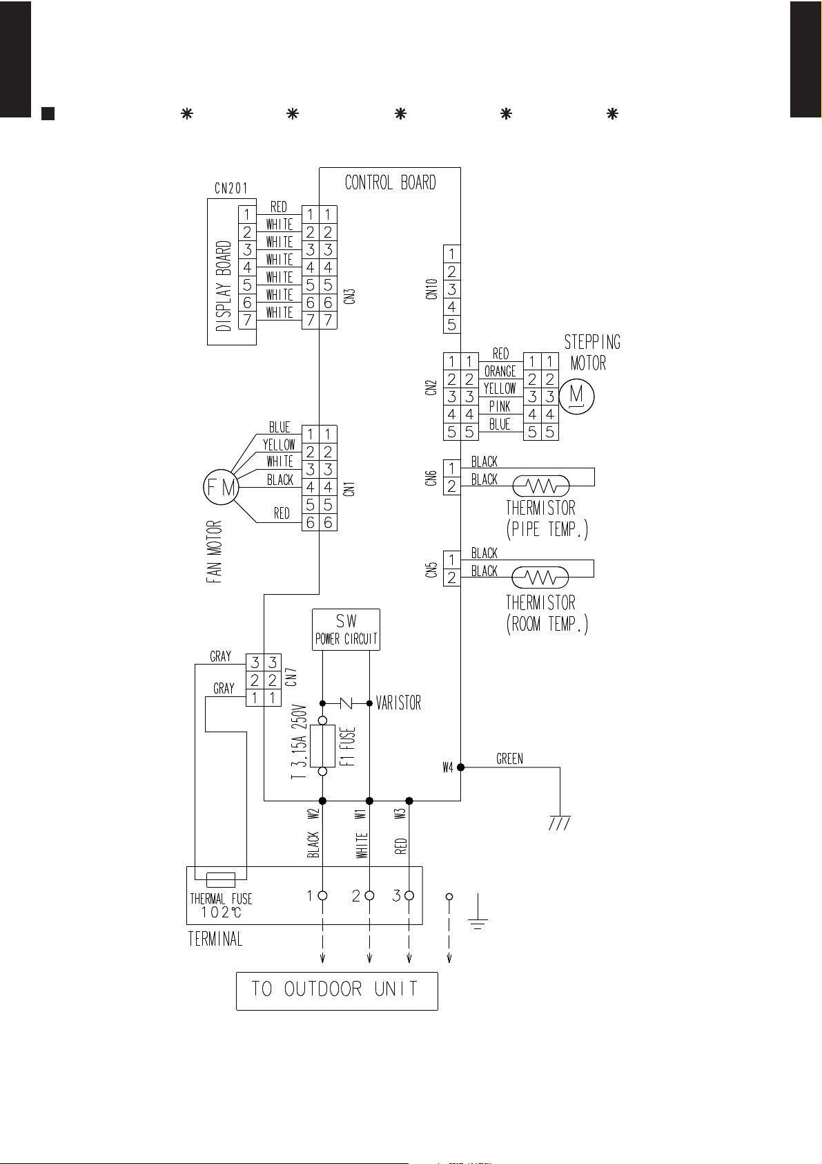
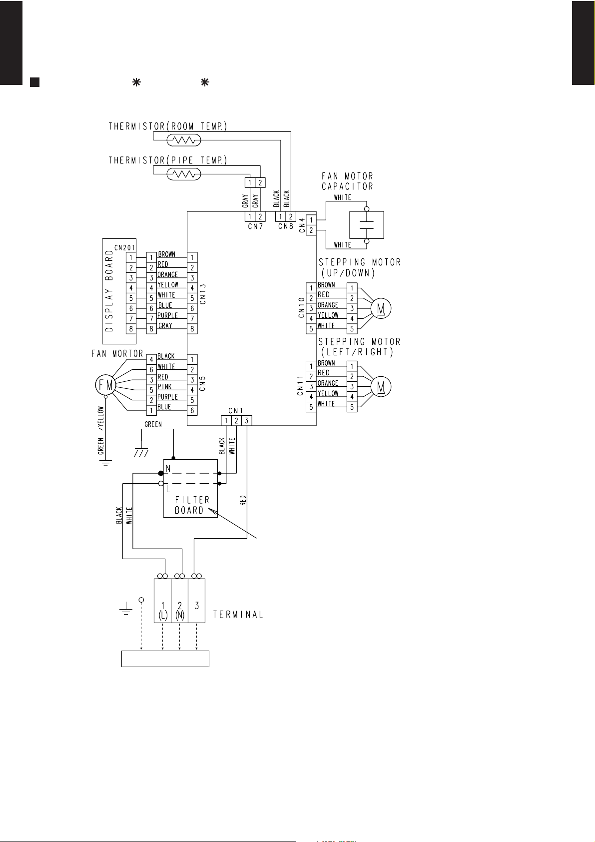
5-4. WALL MOUNTED TYPE
MULTI TYPE
2ROOM TYPE
MODEL : AS A07L, AS A09L, AS A12L, AS A14L, AS A18L
MULTI TYPE
2ROOM TYPE
- (01 - 25) -
Page 27
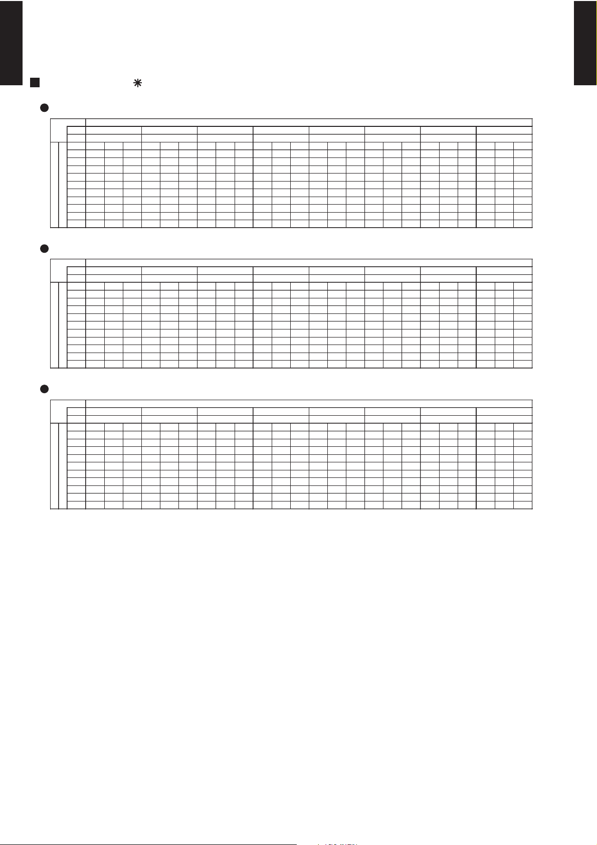
6. CAPACITY TABLE
825
825
825
825
670
825
825
830
Annual
energy
consumption
(KW/h)
EER
(kW/kW )
Class
Annual
energy
consumption
(KW/h)
COP
(kW/kW )
Class
825
825
825
825
695
780
825
825
Indoor model for each
room
Cooling capacity
for each indoor
unit Rated (kW)
Total cooling capacity (kW)
Total Input (kW)
Cooling capacity
for each indoor
unit Max (kW)
Indoor model for each
room
Heating capacity
for each indoor
unit Rated (kW)
Total heating capacity (kW)
Total Input (kW)
Heating capacity
for each indoor
unit Max (kW)
6-1. COMBINATIONS
MULTI TYPE
2ROOM TYPE
MODEL : AO 18L2
COOLING
Room 1 Room 2 Total Room 1 Room 2 Room 1 Room 2 Min. Rated Max. Min. Rated Max.
Min. 14 kBTU 7 7 14 2.30 2.30 2.70 2.70 2.00 4.60 5.40 0.68 1.39 1.68 3.31 A
Max. 24 kBTU 7 9 16 2.35 2.75 2.70 3.20 2.00 5.10 5.90 0.68 1.56 1.84 3.27 A
7 12 19 2.18 3.32 2.50 3.80 2.00 5.50 6.30 0.68 1.65 2.03 3.33 A
7 14 21 1.95 3.55 2.34 4.26 2.00 5.50 6.60 0.68 1.65 2.22 3.33 A
9 9 18 2.70 2.70 3.15 3.15 2.00 5.40 6.30 0.68 1.65 2.06 3.27 A
9 12 21 2.40 3.10 2.87 3.73 2.00 5.50 6.60 0.68 1.65 2.22 3.33 A
9 14 23 2.15 3.35 2.58 4.02 2.00 5.50 6.60 0.68 1.65 2.22 3.33 A
12 12 24 2.75 2.75 3.30 3.30 2.00 5.50 6.60 0.68 1.65 2.22 3.33 A
NOTES
Cooling capacity is based on 27°CDB/19°CWB (indoor temperature) , 35°CDB (outdoor temperature)
The total ability of connected a indoor unit is up to 27000BTU.
HEATING
MULTI TYPE
2ROOM TYPE
Room 1 Room 2 Total Room 1 Room 2 Room 1 Room 2 Min. Rated Max. Min. Rated Max.
Min. 14 kBTU 7 7 14 2.60 2.60 3.20 3.20 2.20 5.20 6.40 0.68 1.34 1.75 3.88 A
Max. 24 kBTU 7 9 16 2.85 3.35 3.40 4.00 2.20 6.20 7.40 0.68 1.65 2.22 3.76 A
7 12 19 2.59 3.71 3.17 4.53 2.20 6.30 7.70 0.68 1.65 2.22 3.82 A
7 14 21 2.36 4.04 2.87 4.93 2.50 6.40 7.80 0.75 1.66 2.22 3.86 A
9 9 18 3.20 3.20 3.85 3.85 2.20 6.40 7.70 0.68 1.65 2.22 3.88 A
9 12 21 2.85 3.45 3.53 4.27 2.20 6.30 7.80 0.75 1.65 2.22 3.82 A
9 14 23 2.61 3.79 3.18 4.62 2.50 6.40 7.80 0.75 1.65 2.22 3.88 A
12 12 24 3.20 3.20 3.90 3.90 2.20 6.40 7.80 0.75 1.65 2.22 3.88 A
NOTES
Heating capacity is based on 20°CDB (indoor temperature) , 7°CDB/6°CWB (outdoor temperature)
The total ability of connected a indoor unit is up to 27000BTU.
- (01 - 26) -
Page 28
MULTI TYPE
Class
Class
Annual
energy
consumption
(KW/h)
Heating capacity
for each indoor
unit Max. (kW)
EER
(kW/kW )
Cooling capacity
for each indoor
unit Max.(kW)
Indoor model for each
room
Indoor model for each
room
COP
(kW/kW )
Cooling capacity
for each indoor
unit Rated(kW)
Total cooling capacity (kW)
Total Input (kW)
Annual
energy
consumption
(KW/h)
Heating capacity
for each indoor
unit Rated (kW)
Total heating capacity (kW)
Total Input (kW)
2ROOM TYPE
MODEL : AO 24L2
MULTI TYPE
2ROOM TYPE
COOLING
Room 1 Room 2 Total Room 1 Room 2 Room 1 Room 2 Min. Rated Max. Min. Rated Max.
Min. 14 kBTU 7 7 14 2.30 2.30 2.70 2.70 2.00 4.60 5.40 0.68 1.39 1.68 695 3.31 A
Max. 30 kBTU 7 9 16 2.35 2.75 2.70 3.20 2.00 5.10 5.90 0.68 1.56 1.84 780 3.27 A
7 12 19 2.18 3.32 2.50 3.80 2.00 5.50 6.30 0.68 1.71 2.03 855 3.22 A
7 14 21 2.02 3.68 2.58 4.72 2.00 5.70 7.30 0.68 1.72 2.62 860 3.31 A
7 18 25 1.80 3.90 2.39 5.21 2.00 5.70 7.60 0.68 1.72 2.77 860 3.31 A
9 9 18 2.70 2.70 3.15 3.15 2.00 5.40 6.30 0.68 1.68 2.06 840 3.21 A
9 12 21 2.44 3.16 3.05 3.95 2.00 5.60 7.00 0.68 1.71 2.58 855 3.27 A
9 14 23 2.23 3.47 2.97 4.63 2.00 5.70 7.60 0.68 1.72 2.77 860 3.31 A
9 18 27 2.00 3.70 2.70 5.00 2.50 5.70 7.70 0.80 1.72 2.77 860 3.31 A
12 12 24 2.80 2.80 3.65 3.65 2.00 5.60 7.30 0.68 1.72 2.77 860 3.26 A
12 14 26 2.59 3.11 3.45 4.15 2.00 5.70 7.60 0.68 1.73 2.77 865 3.29 A
12 18 30 2.39 3.41 3.21 4.59 2.50 5.80 7.80 0.80 1.73 2.77 865 3.35 A
14 14 28 2.90 2.90 3.90 3.90 2.50 5.80 7.80 0.80 1.73 2.77 865 3.35 A
NOTES
Cooling capacity is based on 27°CDB/19°CWB (indoor temperature) , 35°CDB (outdoor temperature)
The total ability of connected a indoor unit is up to 30000BTU.
HEATING
Room 1 Room 2 Total Room 1 Room 2 Room 1 Room 2 Min. Rated Max. Min. Rated Max.
Min. 14 kBTU 7 7 14 2.60 2.60 3.20 3.20 2.20 5.20 6.40 0.68 1.34 1.75 670 3.88 A
Max. 30 kBTU 7 9 16 2.85 3.35 3.40 4.00 2.20 6.20 7.40 0.68 1.70 2.22 850 3.65 A
7 12 19 2.59 3.71 3.25 4.65 2.20 6.30 7.90 0.68 1.69 2.41 845 3.73 A
7 14 21 2.36 4.04 3.13 5.37 2.50 6.40 8.50 0.75 1.67 2.68 835 3.83 A
7 18 25 2.13 4.27 2.97 5.93 2.50 6.40 8.90 0.75 1.65 2.77 825 3.88 A
9 9 18 3.20 3.20 4.00 4.00 2.20 6.40 8.00 0.68 1.70 2.47 850 3.76 A
9 12 21 2.85 3.45 3.80 4.60 2.20 6.30 8.40 0.75 1.68 2.70 840 3.75 A
9 14 23 2.61 3.79 3.63 5.27 2.50 6.40 8.90 0.75 1.66 2.77 830 3.86 A
9 18 27 2.37 4.03 3.30 5.60 2.70 6.40 8.90 0.80 1.64 2.77 820 3.90 A
12 12 24 3.20 3.20 4.45 4.45 2.20 6.40 8.90 0.75 1.67 2.77 835 3.83 A
12 14 26 2.91 3.49 4.09 4.91 2.50 6.40 9.00 0.80 1.65 2.77 825 3.88 A
12 18 30 2.67 3.73 3.75 5.25 2.70 6.40 9.00 0.80 1.64 2.77 820 3.90 A
NOTES
Heating capacity is based on 20°CDB (indoor temperature) , 7°CDB/6°CWB (outdoor temperature)
The total ability of connected a indoor unit is up to 30000BTU.
14 14 28 3.20 3.20 4.40 4.40 2.70 6.40 8.80 0.80 1.64 2.77 820 3.90 A
- (01 - 27) -
Page 29
6-2. COOLING CAPACITY
19°CWB
21°CWB
22°CWB
23°CWB
12°CWB
15°CWB
16°CWB
18°CWB
Indoor temperature
18°CDB
21°CDB
23°CDB
25°CDB
27°CDB
29°CDB
30°CDB
32°CDB
7+14
Outdoor temperature
9+9
Outdoor temperature
7+9
Outdoor temperature
7+12
Outdoor temperature
7+7
Outdoor temperature
30°CDB
32°CDB
12°CWB
15°CWB
16°CWB
18°CWB
19°CWB
21°CWB
22°CWB
23°CWB
32°CDB
Indoor temperature
18°CDB
21°CDB
23°CDB
25°CDB
27°CDB
29°CDB
16°CWB
18°CWB
Indoor temperature
18°CDB
21°CDB
23°CDB
25°CDB
27°CDB
29°CDB
30°CDB
Indoor temperature
19°CWB
21°CWB
22°CWB
23°CWB
12°CWB
15°CWB
30°CDB
32°CDB
18°CDB
21°CDB
23°CDB
25°CDB
16°CWB
18°CWB
27°CDB
29°CDB
Indoor temperature
19°CWB
21°CWB
22°CWB
23°CWB
12°CWB
15°CWB
18°CDB
21°CDB
23°CDB
25°CDB
27°CDB
29°CDB
30°CDB
32°CDB
12°CWB
15°CWB
16°CWB
18°CWB
19°CWB
21°CWB
22°CWB
23°CWB
MULTI TYPE
2ROOM TYPE
MODEL : AO 18L2
INDOOR UNIT : 7000BTU + 7000BTU
°CDB
°CWB
°CDB TC SHC PI TC SHC PI TC SHC PI TC S HC PI TC SHC PI TC SHC PI TC SHC PI TC SHC PI
0 3.58 3.29 0.35 3.99 3.31 0. 36 4.13 3.60 0.36 4.40 3.62 0.36 4.5 4 3.90 0.37 4.81 3.89 0.37 4.94 3.88 0.37 5.08 4.14 0.37
5 3.84 3.41 0.40 4.28 3.43 0. 40 4.42 3.73 0.41 4.71 3.75 0.41 4.8 6 4.04 0.41 5.15 4.03 0.42 5.30 4.02 0.42 5.44 4.29 0.42
10 3.69 3.34 0.50 4.11 3.36 0.50 4.25 3.65 0.51 4.53 3.67 0.51 4.67 3.96 0.51 4.95 3.95 0.52 5.09 3.94 0.52 5.23 4.20 0.52
15 3.79 3.31 0.68 4.22 3.33 0.69 4.37 3.62 0.70 4.65 3.64 0.70 4.80 3.93 0.71 5.09 3.91 0.71 5.23 3.90 0.72 5.37 4.17 0.72
20 4.05 3.34 1.03 4.51 3.37 1.05 4.66 3.66 1.06 4.97 3.67 1.07 5.13 3.96 1.07 5.43 3.95 1.08 5.59 3.94 1.09 5.74 4.20 1.09
25 4.01 3.33 1.06 4.47 3.35 1.08 4.62 3.64 1.08 4.93 3.65 1.09 5.08 3.95 1.10 5.39 3.93 1.11 5.54 3.92 1.12 5.69 4.19 1.12
30 3.84 3.25 1.18 4.28 3.28 1.20 4.42 3.56 1.20 4.71 3.57 1.22 4.86 3.86 1.22 5.15 3.84 1.24 5.30 3.84 1.24 5.44 4.09 1.25
35 4.27 3.44 1.62 4.75 3.46 1.65 4.91 3.76 1.65 5.24 3.77 1.67 5.40 4.07 1.68 5.72 4.06 1.70 5.89 4.05 1.71 6.05 4.32 1.71
40 4.01 3.33 1.78 4.47 3.35 1.81 4.62 3.64 1.82 4.92 3.65 1.84 5.08 3.94 1.85 5.38 3.93 1.87 5.53 3.92 1.88 5.69 4.18 1.88
43 3.84 3.25 1.85 4.28 3.28 1.88 4.42 3.56 1.89 4.71 3.57 1.91 4.86 3.86 1.92 5.15 3.84 1.93 5.30 3.84 1.94 5.44 4.09 1.95
INDOOR UNIT : 7000BTU + 9000BTU
°CDB
°CWB
°CDB TC SHC PI TC SHC PI TC SHC PI TC S HC PI TC SHC PI TC SHC PI TC SHC PI TC SHC PI
0 3.59 3.40 0.36 4.00 3.42 0. 36 4.13 3.72 0.36 4.41 3.73 0.37 4.5 4 4.03 0.37 4.82 4.01 0.37 4.95 4.00 0.37 5.09 4.27 0.38
5 3.85 3.52 0.40 4.28 3.55 0. 41 4.43 3.85 0.41 4.72 3.87 0.41 4.8 7 4.17 0.41 5.16 4.16 0.42 5.31 4.15 0.42 5.45 4.43 0.42
10 3.69 3.45 0.50 4.11 3.47 0.50 4.25 3.77 0.51 4.53 3.79 0.51 4.67 4.09 0.52 4.95 4.07 0.52 5.09 4.06 0.52 5.23 4.34 0.53
15 3.80 3.42 0.68 4.23 3.44 0.69 4.37 3.74 0.70 4.66 3.76 0.70 4.81 4.05 0.71 5.09 4.04 0.72 5.24 4.03 0.72 5.38 4.30 0.72
20 4.96 3.84 1.27 5.52 3.86 1.29 5.71 4.20 1.30 6.09 4.21 1.31 6.27 4.55 1.32 6.65 4.53 1.33 6.84 4.52 1.34 7.03 4.83 1.34
25 4.91 3.82 1.30 5.47 3.84 1.32 5.66 4.18 1.33 6.03 4.19 1.34 6.22 4.53 1.35 6.59 4.51 1.36 6.78 4.50 1.37 6.97 4.80 1.38
30 4.70 3.73 1.45 5.24 3.75 1.47 5.41 4.08 1.48 5.77 4.09 1.49 5.95 4.42 1.50 6.31 4.40 1.52 6.48 4.39 1.52 6.66 4.69 1.53
35 4.66 3.71 1.78 5.19 3.73 1.80 5.37 4.06 1.81 5.72 4.07 1.83 5.90 4.40 1.84 6.25 4.38 1.86 6.43 4.37 1.87 6.61 4.66 1.88
40 4.38 3.59 1.95 4.88 3.61 1.98 5.05 3.93 1.99 5.38 3.94 2.01 5.55 4.26 2.02 5.88 4.24 2.04 6.05 4.23 2.05 6.21 4.52 2.06
43 4.19 3.51 2.02 4.67 3.53 2.06 4.83 3.84 2.07 5.15 3.86 2.09 5.31 4.16 2.10 5.63 4.15 2.12 5.79 4.14 2.13 5.95 4.42 2.14
MULTI TYPE
2ROOM TYPE
INDOOR UNIT : 7000BTU + 12000BTU
°CDB
°CWB
°CDB TC SHC PI TC SHC PI TC SHC PI TC S HC PI TC SHC PI TC SHC PI TC SHC PI TC SHC PI
0 4.13 3.74 0.42 4.60 3.77 0. 43 4.75 4.09 0.43 5.07 4.11 0.44 5.2 2 4.43 0.44 5.54 4.42 0.44 5.69 4.41 0.44 5.85 4.70 0.45
5 4.42 3.88 0.47 4.93 3.90 0. 48 5.09 4.24 0.48 5.43 4.26 0.49 5.6 0 4.59 0.49 5.93 4.58 0.50 6.10 4.57 0.50 6.27 4.87 0.50
10 4.24 3.80 0.59 4.73 3.82 0.60 4.89 4.15 0.60 5.21 4.17 0.61 5.37 4.50 0.61 5.70 4.48 0.62 5.86 4.47 0.62 6.02 4.77 0.62
15 4.81 3.95 0.90 5.36 3.98 0.91 5.54 4.32 0.91 5.91 4.34 0.92 6.09 4.68 0.93 6.46 4.67 0.94 6.64 4.66 0.94 6.82 4.97 0.95
20 4.98 3.97 1.29 5.55 3.99 1.31 5.74 4.34 1.32 6.12 4.36 1.33 6.31 4.70 1.34 6.69 4.69 1.35 6.88 4.68 1.36 7.06 4.99 1.37
25 4.94 3.95 1.33 5.50 3.98 1.35 5.69 4.32 1.35 6.07 4.34 1.37 6.25 4.68 1.37 6.63 4.67 1.39 6.82 4.66 1.39 7.00 4.97 1.40
30 4.73 3.86 1.48 5.26 3.89 1.50 5.44 4.22 1.51 5.80 4.24 1.52 5.98 4.58 1.53 6.34 4.56 1.54 6.52 4.55 1.55 6.70 4.86 1.56
35 4.98 3.93 1.96 5.54 3.95 1.99 5.73 4.30 2.00 6.11 4.31 2.02 6.30 4.66 2.03 6.68 4.64 2.05 6.87 4.63 2.06 7.06 4.94 2.07
40 4.68 3.80 2.15 5.21 3.83 2.19 5.39 4.16 2.20 5.74 4.18 2.22 5.92 4.51 2.23 6.28 4.49 2.26 6.45 4.48 2.27 6.63 4.78 2.28
43 4.48 3.72 2.27 4.99 3.75 2.35 5.16 4.07 2.35 5.50 4.09 2.35 5.67 4.41 2.35 6.01 4.39 2.35 6.18 4.39 2.35 6.35 4.68 2.35
INDOOR UNIT : 7000BTU + 14000BTU
°CDB
°CWB
°CDB TC SHC PI TC SHC PI TC SHC PI TC S HC PI TC SHC PI TC SHC PI TC SHC PI TC SHC PI
0 3.82 3.69 0.41 4.26 3.72 0. 41 4.40 4.04 0.42 4.69 4.06 0.42 4.8 4 4.38 0.42 5.13 4.36 0.43 5.28 4.35 0.43 5.42 4.65 0.43
5 3.96 3.76 0.46 4.41 3.79 0. 47 4.56 4.12 0.47 4.86 4.13 0.47 5.0 1 4.46 0.48 5.31 4.45 0.48 5.46 4.44 0.48 5.61 4.73 0.49
10 3.82 3.69 0.57 4.26 3.72 0.58 4.40 4.04 0.58 4.69 4.06 0.59 4.84 4.38 0.59 5.13 4.36 0.60 5.28 4.35 0.60 5.42 4.65 0.60
15 3.97 3.69 0.81 4.43 3.71 0.82 4.58 4.03 0.82 4.88 4.05 0.83 5.03 4.37 0.84 5.33 4.36 0.85 5.48 4.35 0.85 5.63 4.64 0.85
20 4.55 4.01 1.27 5.07 4.03 1.29 5.24 4.38 1.30 5.58 4.40 1.31 5.76 4.75 1.32 6.10 4.73 1.33 6.27 4.72 1.34 6.45 5.04 1.35
25 4.58 3.93 1.31 5.10 3.96 1.33 5.28 4.30 1.33 5.63 4.32 1.35 5.80 4.66 1.35 6.15 4.64 1.37 6.32 4.63 1.37 6.50 4.94 1.38
30 4.34 3.82 1.45 4.83 3.85 1.48 5.00 4.18 1.48 5.33 4.20 1.50 5.49 4.53 1.51 5.82 4.51 1.52 5.98 4.51 1.53 6.15 4.81 1.54
35 5.21 4.14 2.14 5.81 4.17 2.18 6.01 4.53 2.19 6.40 4.54 2.21 6.60 4.91 2.22 7.00 4.89 2.24 7.19 4.88 2.25 7.39 5.20 2.26
40 4.85 3.99 2.31 5.40 4.01 2.35 5.59 4.36 2.36 5.95 4.38 2.39 6.14 4.72 2.40 6.51 4.71 2.42 6.69 4.70 2.43 6.87 5.01 2.45
43 4.17 3.69 1.97 4.65 3.72 2.00 4.80 4.04 2.01 5.12 4.06 2.03 5.28 4.38 2.04 5.60 4.36 2.06 5.76 4.35 2.07 5.91 4.64 2.08
INDOOR UNIT : 9000BTU + 9000BTU
°CDB
°CWB
°CDB TC SHC PI TC SHC PI TC SHC PI TC S HC PI TC SHC PI TC SHC PI TC SHC PI TC SHC PI
0 4.13 3.77 0.43 4.60 3.79 0. 43 4.75 4.12 0.44 5.07 4.13 0.44 5.2 2 4.46 0.44 5.54 4.45 0.45 5.69 4.44 0.45 5.85 4.74 0.45
5 4.42 3.90 0.48 4.93 3.93 0. 49 5.09 4.27 0.49 5.43 4.28 0.50 5.6 0 4.62 0.50 5.93 4.61 0.50 6.10 4.60 0.51 6.27 4.91 0.51
10 4.24 3.82 0.60 4.73 3.85 0.61 4.89 4.18 0.61 5.21 4.19 0.62 5.37 4.53 0.62 5.70 4.51 0.63 5.86 4.50 0.63 6.02 4.80 0.63
15 4.01 3.63 0.76 4.47 3.65 0.77 4.62 3.97 0.77 4.92 3.98 0.78 5.08 4.30 0.78 5.38 4.28 0.79 5.53 4.28 0.80 5.68 4.56 0.80
20 4.79 3.84 1.31 5.33 3.86 1.33 5.51 4.20 1.34 5.88 4.21 1.35 6.06 4.55 1.36 6.42 4.53 1.37 6.61 4.52 1.38 6.79 4.83 1.39
25 4.84 3.90 1.35 5.39 3.92 1.37 5.58 4.26 1.37 5.95 4.28 1.39 6.13 4.62 1.39 6.50 4.60 1.41 6.68 4.60 1.42 6.87 4.90 1.42
30 4.63 3.81 1.50 5.16 3.83 1.52 5.34 4.17 1.53 5.69 4.18 1.54 5.86 4.52 1.55 6.22 4.50 1.57 6.39 4.49 1.57 6.57 4.79 1.58
35 4.98 3.95 1.99 5.54 3.98 2.02 5.73 4.33 2.03 6.11 4.34 2.05 6.30 4.69 2.06 6.68 4.67 2.08 6.87 4.66 2.09 7.06 4.97 2.10
40 4.68 3.83 2.19 5.21 3.85 2.22 5.39 4.19 2.23 5.74 4.20 2.25 5.92 4.54 2.27 6.28 4.52 2.29 6.45 4.51 2.30 6.63 4.82 2.31
43 4.48 3.75 2.27 4.99 3.77 2.35 5.16 4.10 2.35 5.50 4.11 2.35 5.67 4.44 2.35 6.01 4.42 2.35 6.18 4.41 2.35 6.35 4.71 2.35
TC : Total CapaCity (kW)
SHC: Sensible Heat Capacity (kW)
PI : Power Input (kW)
- (01 - 28) -
Page 30
MULTI TYPE
19°CWB
21°CWB
22°CWB
23°CWB
12°CWB
15°CWB
16°CWB
18°CWB
27°CDB
29°CDB
30°CDB
32°CDB
18°CDB
21°CDB
23°CDB
25°CDB
Indoor temperature
19°CWB
21°CWB
22°CWB
23°CWB
12°CWB
15°CWB
16°CWB
18°CWB
Indoor temperature
18°CDB
21°CDB
23°CDB
25°CDB
27°CDB
29°CDB
30°CDB
32°CDB
Indoor temperature
19°CWB
21°CWB
22°CWB
23°CWB
12°CWB
15°CWB
16°CWB
18°CWB
27°CDB
29°CDB
30°CDB
32°CDB
18°CDB
21°CDB
23°CDB
25°CDB
9+12
Outdoor temperature
12+12
Outdoor temperature
9+14
Outdoor temperature
2ROOM TYPE
MODEL : AO 18L2
MULTI TYPE
2ROOM TYPE
INDOOR UNIT : 9000BTU + 12000BTU
°CDB
°CWB
°CDB TC SHC PI TC SHC PI TC SHC PI TC S HC PI TC SHC PI TC SHC PI TC SHC PI TC SHC PI
0 3.82 3.64 0.41 4.26 3.66 0. 41 4.40 3.98 0.42 4.69 4.00 0.42 4.8 4 4.32 0.42 5.13 4.30 0.43 5.28 4.29 0.43 5.42 4.58 0.43
5 3.96 3.71 0.46 4.41 3.73 0. 47 4.56 4.06 0.47 4.86 4.07 0.47 5.0 1 4.40 0.48 5.31 4.38 0.48 5.46 4.37 0.48 5.61 4.67 0.49
10 3.82 3.64 0.57 4.26 3.66 0.58 4.40 3.98 0.58 4.69 4.00 0.59 4.84 4.32 0.59 5.13 4.30 0.60 5.28 4.29 0.60 5.42 4.58 0.60
15 3.97 3.64 0.81 4.43 3.66 0.82 4.58 3.98 0.82 4.88 3.99 0.83 5.03 4.31 0.84 5.33 4.29 0.85 5.48 4.29 0.85 5.63 4.57 0.85
20 4.51 3.91 1.27 5.02 3.94 1.29 5.19 4.28 1.30 5.53 4.30 1.31 5.70 4.64 1.32 6.05 4.62 1.33 6.22 4.61 1.34 6.39 4.92 1.35
25 4.63 3.91 1.31 5.15 3.94 1.33 5.33 4.28 1.33 5.68 4.29 1.35 5.86 4.64 1.35 6.21 4.62 1.37 6.38 4.61 1.37 6.56 4.92 1.38
30 4.38 3.80 1.45 4.88 3.83 1.48 5.04 4.16 1.48 5.38 4.18 1.50 5.54 4.51 1.51 5.88 4.49 1.52 6.04 4.48 1.53 6.21 4.78 1.54
35 5.21 4.08 2.14 5.81 4.11 2.18 6.01 4.46 2.19 6.40 4.48 2.21 6.60 4.84 2.22 7.00 4.82 2.24 7.19 4.81 2.25 7.39 5.13 2.26
40 4.85 3.93 2.31 5.40 3.95 2.35 5.59 4.30 2.36 5.95 4.31 2.39 6.14 4.66 2.40 6.51 4.64 2.42 6.69 4.63 2.43 6.87 4.94 2.45
43 4.17 3.64 1.97 4.65 3.66 2.00 4.80 3.98 2.01 5.12 4.00 2.03 5.28 4.31 2.04 5.60 4.30 2.06 5.76 4.29 2.07 5.91 4.58 2.08
INDOOR UNIT : 9000BTU + 14000BTU
°CDB
°CWB
°CDB TC SHC PI TC SHC PI TC SHC PI TC S HC PI TC SHC PI TC SHC PI TC SHC PI TC SHC PI
0 3.65 3.65 0.39 4.07 3.67 0. 40 4.20 3.99 0.40 4.48 4.01 0.40 4.6 2 4.32 0.40 4.90 4.31 0.41 5.04 4.30 0.41 5.17 4.59 0.41
5 3.78 3.72 0.44 4.21 3.74 0. 45 4.35 4.07 0.45 4.64 4.08 0.45 4.7 9 4.41 0.45 5.07 4.39 0.46 5.22 4.38 0.46 5.36 4.68 0.46
10 3.65 3.65 0.55 4.07 3.67 0.55 4.20 3.99 0.56 4.48 4.01 0.56 4.62 4.32 0.57 4.90 4.31 0.57 5.04 4.30 0.57 5.17 4.59 0.58
15 4.64 4.04 0.94 5.16 4.07 0.96 5.34 4.42 0.96 5.69 4.44 0.97 5.87 4.79 0.98 6.22 4.78 0.99 6.40 4.77 0.99 6.57 5.08 1.00
20 4.35 3.82 1.32 4.85 3.85 1.34 5.02 4.18 1.34 5.35 4.20 1.36 5.51 4.53 1.36 5.84 4.52 1.38 6.01 4.51 1.38 6.17 4.81 1.39
25 4.60 3.93 1.35 5.13 3.96 1.37 5.30 4.30 1.38 5.65 4.32 1.39 5.82 4.66 1.40 6.17 4.64 1.41 6.35 4.64 1.42 6.52 4.94 1.43
30 4.35 3.82 1.50 4.85 3.85 1.53 5.02 4.18 1.53 5.35 4.20 1.55 5.51 4.53 1.56 5.84 4.52 1.57 6.01 4.51 1.58 6.17 4.81 1.59
35 5.21 4.19 2.14 5.81 4.22 2.18 6.01 4.59 2.19 6.40 4.60 2.21 6.60 4.97 2.22 7.00 4.95 2.24 7.19 4.94 2.25 7.39 5.27 2.26
40 4.85 4.04 2.31 5.40 4.06 2.35 5.59 4.42 2.36 5.95 4.43 2.39 6.14 4.79 2.40 6.51 4.77 2.42 6.69 4.76 2.43 6.87 5.08 2.45
43 4.17 3.74 1.97 4.65 3.77 2.00 4.80 4.09 2.01 5.12 4.11 2.03 5.28 4.44 2.04 5.60 4.42 2.06 5.76 4.41 2.07 5.91 4.71 2.08
INDOOR UNIT : 12000BTU + 12000BTU
°CDB
°CWB
°CDB TC SHC PI TC SHC PI TC SHC PI TC S HC PI TC SHC PI TC SHC PI TC SHC PI TC SHC PI
0 4.38 3.96 0.47 4.88 3.98 0. 47 5.05 4.33 0.48 5.38 4.35 0.48 5.5 4 4.69 0.48 5.88 4.67 0.49 6.04 4.67 0.49 6.21 4.98 0.49
5 4.54 4.03 0.53 5.05 4.06 0. 53 5.23 4.41 0.54 5.57 4.42 0.54 5.7 4 4.78 0.54 6.09 4.76 0.55 6.26 4.75 0.55 6.43 5.07 0.56
10 4.38 3.96 0.65 4.88 3.98 0.66 5.05 4.33 0.67 5.38 4.35 0.67 5.54 4.69 0.68 5.88 4.67 0.68 6.04 4.67 0.69 6.21 4.98 0.69
15 4.64 3.98 0.94 5.16 4.01 0.96 5.34 4.35 0.96 5.69 4.37 0.97 5.87 4.72 0.98 6.22 4.70 0.99 6.40 4.69 0.99 6.57 5.01 1.00
20 4.35 3.77 1.32 4.85 3.79 1.34 5.02 4.12 1.34 5.35 4.13 1.36 5.51 4.46 1.36 5.84 4.45 1.38 6.01 4.44 1.38 6.17 4.73 1.39
25 4.60 3.87 1.35 5.13 3.90 1.37 5.30 4.23 1.38 5.65 4.25 1.39 5.82 4.59 1.40 6.17 4.57 1.41 6.35 4.56 1.42 6.52 4.87 1.43
30 4.35 3.77 1.50 4.85 3.79 1.53 5.02 4.12 1.53 5.35 4.13 1.55 5.51 4.46 1.56 5.84 4.45 1.57 6.01 4.44 1.58 6.17 4.73 1.59
35 5.21 4.13 2.14 5.81 4.16 2.18 6.01 4.52 2.19 6.40 4.53 2.21 6.60 4.89 2.22 7.00 4.88 2.24 7.19 4.87 2.25 7.39 5.19 2.26
40 4.85 3.98 2.31 5.40 4.00 2.35 5.59 4.35 2.36 5.95 4.37 2.39 6.14 4.71 2.40 6.51 4.70 2.42 6.69 4.69 2.43 6.87 5.00 2.45
43 4.17 3.68 1.97 4.65 3.71 2.00 4.80 4.03 2.01 5.12 4.05 2.03 5.28 4.37 2.04 5.60 4.35 2.06 5.76 4.34 2.07 5.91 4.63 2.08
TC : Total CapaCity (kW)
SHC: Sensible Heat Capacity (kW)
PI : Power Input (kW)
- (01 - 29) -
Page 31

MULTI TYPE
19°CWB
21°CWB
22°CWB
23°CWB
12°CWB
15°CWB
16°CWB
18°CWB
27°CDB
29°CDB
30°CDB
32°CDB
18°CDB
21°CDB
23°CDB
25°CDB
Indoor temperature
19°CWB
21°CWB
22°CWB
23°CWB
12°CWB
15°CWB
16°CWB
18°CWB
27°CDB
29°CDB
30°CDB
32°CDB
18°CDB
21°CDB
23°CDB
25°CDB
Indoor temperature
19°CWB
21°CWB
22°CWB
23°CWB
12°CWB
15°CWB
16°CWB
18°CWB
27°CDB
29°CDB
30°CDB
32°CDB
18°CDB
21°CDB
23°CDB
25°CDB
Indoor temperature
19°CWB
21°CWB
22°CWB
23°CWB
12°CWB
15°CWB
16°CWB
18°CWB
Indoor temperature
18°CDB
21°CDB
23°CDB
25°CDB
27°CDB
29°CDB
30°CDB
32°CDB
7+18
Outdoor temperature
7+12
Outdoor temperature
7+14
Outdoor temperature
7+7
Outdoor temperature
7+9
Outdoor temperature
23°CWB
29°CDB
30°CDB
32°CDB
12°CWB
15°CWB
16°CWB
18°CWB
19°CWB
21°CWB
22°CWB
Indoor temperature
27°CDB
18°CDB
21°CDB
23°CDB
25°CDB
2ROOM TYPE
MODEL : AO 24L2
MULTI TYPE
2ROOM TYPE
INDOOR UNIT : 7000BTU + 7000BTU
°CDB
°CWB
°CDB TC SHC PI TC SHC PI TC SHC PI TC SHC PI TC SHC PI TC SHC PI TC SHC PI TC SHC PI
0 3.58 3. 29 0.35 3.99 3.31 0.36 4.13 3.60 0.36 4.40 3.62 0.36 4.54 3.90 0.37 4.81 3.89 0.37 4.94 3.88 0.37 5.08 4.14 0.37
5 3.84 3. 41 0.40 4.28 3.43 0.40 4.42 3.73 0.41 4.71 3.75 0.41 4.86 4.04 0.41 5.15 4.03 0.42 5.30 4.02 0.42 5.44 4.29 0.42
10 3.69 3.34 0.50 4.11 3.36 0.50 4.25 3.65 0.51 4.53 3.67 0.51 4.67 3.96 0.51 4.95 3.95 0 .52 5.09 3.94 0.52 5.23 4.20 0.52
15 3.79 3.31 0.68 4.22 3.33 0.69 4.37 3.62 0.70 4.65 3.64 0.70 4.80 3.93 0.71 5.09 3.91 0 .71 5.23 3.90 0.72 5.37 4.17 0.72
20 4.05 3.34 1.03 4.51 3.37 1.05 4.66 3.66 1.06 4.97 3.67 1.07 5.13 3.96 1.07 5.43 3.95 1 .08 5.59 3.94 1.09 5.74 4.20 1.09
25 4.01 3.33 1.06 4.47 3.35 1.08 4.62 3.64 1.08 4.93 3.65 1.09 5.08 3.95 1.10 5.39 3.93 1 .11 5.54 3.92 1.12 5.69 4.19 1.12
30 3.84 3.25 1.18 4.28 3.28 1.20 4.42 3.56 1.20 4.71 3.57 1.22 4.86 3.86 1.22 5.15 3.84 1 .24 5.30 3.84 1.24 5.44 4.09 1.25
35 4.27 3.44 1.62 4.75 3.46 1.65 4.91 3.76 1.65 5.24 3.77 1.67 5.40 4.07 1.68 5.72 4.06 1 .70 5.89 4.05 1.71 6.05 4.32 1.71
40 4.01 3.33 1.78 4.47 3.35 1.81 4.62 3.64 1.82 4.92 3.65 1.84 5.08 3.94 1.85 5.38 3.93 1 .87 5.53 3.92 1.88 5.69 4.18 1.88
43 3.84 3.25 1.85 4.28 3.28 1.88 4.42 3.56 1.89 4.71 3.57 1.91 4.86 3.86 1.92 5.15 3.84 1 .93 5.30 3.84 1.94 5.44 4.09 1.95
INDOOR UNIT : 7000BTU + 9000BTU
°CDB
°CWB
°CDB TC SHC PI TC SHC PI TC SHC PI TC SHC PI TC SHC PI TC SHC PI TC SHC PI TC SHC PI
0 3.59 3. 40 0.36 4.00 3.42 0.36 4.13 3.72 0.36 4.41 3.73 0.37 4.54 4.03 0.37 4.82 4.01 0.37 4.95 4.00 0.37 5.09 4.27 0.38
5 3.85 3. 52 0.40 4.28 3.55 0.41 4.43 3.85 0.41 4.72 3.87 0.41 4.87 4.17 0.41 5.16 4.16 0.42 5.31 4.15 0.42 5.45 4.43 0.42
10 3.69 3.45 0.50 4.11 3.47 0.50 4.25 3.77 0.51 4.53 3.79 0.51 4.67 4.09 0.52 4.95 4.07 0 .52 5.09 4.06 0.52 5.23 4.34 0.53
15 3.80 3.42 0.68 4.23 3.44 0.69 4.37 3.74 0.70 4.66 3.76 0.70 4.81 4.05 0.71 5.09 4.04 0 .72 5.24 4.03 0.72 5.38 4.30 0.72
20 4.96 3.84 1.27 5.52 3.86 1.29 5.71 4.20 1.30 6.09 4.21 1.31 6.27 4.55 1.32 6.65 4.53 1 .33 6.84 4.52 1.34 7.03 4.83 1.34
25 4.91 3.82 1.30 5.47 3.84 1.32 5.66 4.18 1.33 6.03 4.19 1.34 6.22 4.53 1.35 6.59 4.51 1 .36 6.78 4.50 1.37 6.97 4.80 1.38
30 4.70 3.73 1.45 5.24 3.75 1.47 5.41 4.08 1.48 5.77 4.09 1.49 5.95 4.42 1.50 6.31 4.40 1 .52 6.48 4.39 1.52 6.66 4.69 1.53
35 4.66 3.71 1.78 5.19 3.73 1.80 5.37 4.06 1.81 5.72 4.07 1.83 5.90 4.40 1.84 6.25 4.38 1 .86 6.43 4.37 1.87 6.61 4.66 1.88
40 4.38 3.59 1.95 4.88 3.61 1.98 5.05 3.93 1.99 5.38 3.94 2.01 5.55 4.26 2.02 5.88 4.24 2 .04 6.05 4.23 2.05 6.21 4.52 2.06
43 4.19 3.51 2.02 4.67 3.53 2.06 4.83 3.84 2.07 5.15 3.86 2.09 5.31 4.16 2.10 5.63 4.15 2 .12 5.79 4.14 2.13 5.95 4.42 2.14
INDOOR UNIT : 7000BTU + 12000BTU
°CDB
°CWB
°CDB TC SHC PI TC SHC PI TC SHC PI TC SHC PI TC SHC PI TC SHC PI TC SHC PI TC SHC PI
0 4.13 3. 74 0.42 4.60 3.77 0.43 4.75 4.09 0.43 5.07 4.11 0.44 5.22 4.43 0.44 5.54 4.42 0.44 5.69 4.41 0.44 5.85 4.70 0.45
5 4.42 3. 88 0.47 4.93 3.90 0.48 5.09 4.24 0.48 5.43 4.26 0.49 5.60 4.59 0.49 5.93 4.58 0.50 6.10 4.57 0.50 6.27 4.87 0.50
10 4.24 3.80 0.59 4.73 3.82 0.60 4.89 4.15 0.60 5.21 4.17 0.61 5.37 4.50 0.61 5.70 4.48 0 .62 5.86 4.47 0.62 6.02 4.77 0.62
15 4.81 3.95 0.90 5.36 3.98 0.91 5.54 4.32 0.91 5.91 4.34 0.92 6.09 4.68 0.93 6.46 4.67 0 .94 6.64 4.66 0.94 6.82 4.97 0.95
20 4.98 3.97 1.29 5.55 3.99 1.31 5.74 4.34 1.32 6.12 4.36 1.33 6.31 4.70 1.34 6.69 4.69 1 .35 6.88 4.68 1.36 7.06 4.99 1.37
25 4.94 3.95 1.33 5.50 3.98 1.35 5.69 4.32 1.35 6.07 4.34 1.37 6.25 4.68 1.37 6.63 4.67 1 .39 6.82 4.66 1.39 7.00 4.97 1.40
30 4.73 3.86 1.48 5.26 3.89 1.50 5.44 4.22 1.51 5.80 4.24 1.52 5.98 4.58 1.53 6.34 4.56 1 .54 6.52 4.55 1.55 6.70 4.86 1.56
35 4.98 3.93 1.96 5.54 3.95 1.99 5.73 4.30 2.00 6.11 4.31 2.02 6.30 4.66 2.03 6.68 4.64 2 .05 6.87 4.63 2.06 7.06 4.94 2.07
40 4.68 3.80 2.15 5.21 3.83 2.19 5.39 4.16 2.20 5.74 4.18 2.22 5.92 4.51 2.23 6.28 4.49 2 .26 6.45 4.48 2.27 6.63 4.78 2.28
43 4.48 3.72 2.27 4.99 3.75 2.35 5.16 4.07 2.35 5.50 4.09 2.35 5.67 4.41 2.35 6.01 4.39 2 .35 6.18 4.39 2.35 6.35 4.68 2.35
INDOOR UNIT : 7000BTU + 14000BTU
°CDB
°CWB
°CDB TC SHC PI TC SHC PI TC SHC PI TC SHC PI TC SHC PI TC SHC PI TC SHC PI TC SHC PI
0 4.23 3. 98 0.48 4.71 4.00 0.49 4.87 4.35 0.49 5.19 4.37 0.50 5.35 4.71 0.50 5.67 4.70 0.50 5.84 4.69 0.51 6.00 5.00 0.51
5 4.38 4. 05 0.54 4.88 4.08 0.55 5.05 4.43 0.55 5.38 4.45 0.56 5.54 4.80 0.56 5.88 4.79 0.57 6.04 4.78 0.57 6.21 5.10 0.57
10 4.23 3.98 0.67 4.71 4.00 0.68 4.87 4.35 0.69 5.19 4.37 0.70 5.35 4.71 0.70 5.67 4.70 0 .71 5.84 4.69 0.71 6.00 5.00 0.71
15 4.39 3.97 0.95 4.90 4.00 0.97 5.06 4.34 0.97 5.40 4.36 0.98 5.56 4.71 0.99 5.90 4.69 1 .00 6.06 4.68 1.00 6.23 5.00 1.01
20 5.03 4.32 1.50 5.60 4.34 1.53 5.79 4.72 1.53 6.18 4.74 1.55 6.37 5.12 1.56 6.75 5.10 1 .57 6.94 5.09 1.58 7.13 5.43 1.59
25 5.07 4.23 1.54 5.65 4.26 1.57 5.84 4.63 1.57 6.22 4.65 1.59 6.42 5.02 1.60 6.80 5.00 1 .61 6.99 4.99 1.62 7.19 5.32 1.63
30 4.80 4.12 1.71 5.34 4.14 1.74 5.53 4.50 1.75 5.89 4.52 1.77 6.07 4.88 1.78 6.44 4.86 1 .79 6.62 4.85 1.80 6.80 5.18 1.81
35 5.77 4.46 2.53 6.42 4.49 2.57 6.64 4.87 2.58 7.08 4.89 2.61 7.30 5.28 2.62 7.74 5.26 2 .65 7.96 5.25 2.66 8.18 5.60 2.67
40 5.36 4.29 2.67 5.97 4.32 2.77 6.18 4.69 2.77 6.59 4.71 2.77 6.79 5.09 2.77 7.20 5.07 2 .77 7.40 5.06 2.77 7.60 5.40 2.77
43 4.61 3.98 2.27 5.14 4.00 2.35 5.31 4.35 2.35 5.66 4.37 2.35 5.84 4.71 2.35 6.19 4.70 2 .35 6.37 4.69 2.35 6.54 5.00 2.35
INDOOR UNIT : 7000BTU + 18000BTU
°CDB
°CWB
°CDB TC SHC PI TC SHC PI TC SHC PI TC SHC PI TC SHC PI TC SHC PI TC SHC PI TC SHC PI
0 5.04 4. 34 0.55 5.62 4.37 0.56 5.81 4.75 0.57 6.19 4.77 0.57 6.38 5.15 0.57 6.77 5.13 0.58 6.96 5.12 0.58 7.15 5.46 0.59
5 5.04 4. 34 0.66 5.62 4.37 0.67 5.81 4.75 0.67 6.19 4.77 0.68 6.38 5.15 0.68 6.77 5.13 0.69 6.96 5.12 0.69 7.15 5.46 0.69
10 4.83 4.25 0.79 5.38 4.27 0.80 5.56 4.64 0.80 5.93 4.66 0.81 6.11 5.03 0.82 6.48 5.01 0 .82 6.66 5.00 0.83 6.84 5.34 0.83
15 5.04 4.25 1.16 5.62 4.27 1.18 5.81 4.64 1.18 6.19 4.66 1.19 6.38 5.03 1.20 6.77 5.01 1 .21 6.96 5.00 1.22 7.15 5.34 1.22
20 5.67 4.40 2.17 6.32 4.43 2.20 6.54 4.81 2.21 6.97 4.83 2.24 7.18 5.21 2.25 7.61 5.20 2 .27 7.83 5.19 2.28 8.04 5.53 2.29
25 5.79 4.45 2.09 6.45 4.47 2.12 6.67 4.86 2.14 7.11 4.88 2.16 7.33 5.27 2.17 7.77 5.25 2 .19 7.99 5.24 2.20 8.21 5.59 2.21
30 5.90 4.49 2.27 6.58 4.52 2.31 6.80 4.91 2.32 7.25 4.93 2.34 7.47 5.32 2.35 7.92 5.30 2 .38 8.14 5.29 2.39 8.37 5.65 2.40
35 6.00 4.53 2.67 6.69 4.56 2.77 6.92 4.95 2.77 7.37 4.97 2.77 7.60 5.37 2.77 8.06 5.35 2 .77 8.28 5.34 2.77 8.51 5.70 2.77
40 5.40 4.29 2.67 6.02 4.32 2.77 6.22 4.69 2.77 6.63 4.71 2.77 6.84 5.09 2.77 7.25 5.07 2 .77 7.46 5.06 2.77 7.66 5.40 2.77
43 4.50 3.91 2.27 5.02 3.94 2.35 5.19 4.28 2.35 5.53 4.29 2.35 5.70 4.64 2.35 6.04 4.62 2 .35 6.21 4.61 2.35 6.38 4.92 2.35
TC : Total capacity (kW)
SHC : Sensible Heat capacity (kW)
PI : Power Input (kW)
- (01 - 30) -
Page 32

MULTI TYPE
23°CWB
18°CWB
19°CWB
21°CWB
22°CWB
Indoor temperature
19°CWB
21°CWB
22°CWB
23°CWB
12°CWB
15°CWB
16°CWB
18°CWB
27°CDB
29°CDB
30°CDB
32°CDB
18°CDB
21°CDB
23°CDB
25°CDB
Indoor temperature
19°CWB
21°CWB
22°CWB
23°CWB
12°CWB
15°CWB
16°CWB
18°CWB
27°CDB
29°CDB
30°CDB
32°CDB
18°CDB
21°CDB
23°CDB
25°CDB
Indoor temperature
19°CWB
21°CWB
22°CWB
23°CWB
12°CWB
15°CWB
16°CWB
18°CWB
27°CDB
29°CDB
30°CDB
32°CDB
18°CDB
21°CDB
23°CDB
25°CDB
Indoor temperature
19°CWB
21°CWB
22°CWB
23°CWB
12°CWB
15°CWB
16°CWB
18°CWB
27°CDB
29°CDB
30°CDB
32°CDB
18°CDB
21°CDB
23°CDB
25°CDB
Indoor temperature
12°CWB
18°CDB
21°CDB
30°CDB
32°CDB
12+12
Outdoor temperature
23°CDB
25°CDB
27°CDB
29°CDB
15°CWB
16°CWB
9+14
Outdoor temperature
9+18
Outdoor temperature
9+9
Outdoor temperature
9+12
Outdoor temperature
2ROOM TYPE
MODEL : AO 24L2
MULTI TYPE
2ROOM TYPE
INDOOR UNIT : 9000BTU + 9000BTU
°CDB
°CWB
°CDB TC SHC PI TC SHC PI TC SHC PI TC SHC PI TC SHC PI TC SHC PI TC SHC PI TC SHC PI
0 4.13 3. 77 0.43 4.60 3.79 0.43 4.75 4.12 0.44 5.07 4.13 0.44 5.22 4.46 0.44 5.54 4.45 0.45 5.69 4.44 0.45 5.85 4.74 0.45
5 4.42 3. 90 0.48 4.93 3.93 0.49 5.09 4.27 0.49 5.43 4.28 0.50 5.60 4.62 0.50 5.93 4.61 0.50 6.10 4.60 0.51 6.27 4.91 0.51
10 4.24 3.82 0.60 4.73 3.85 0.61 4.89 4.18 0.61 5.21 4.19 0.62 5.37 4.53 0.62 5.70 4.51 0 .63 5.86 4.50 0.63 6.02 4.80 0.63
15 4.01 3.63 0.76 4.47 3.65 0.77 4.62 3.97 0.77 4.92 3.98 0.78 5.08 4.30 0.78 5.38 4.28 0 .79 5.53 4.28 0.80 5.68 4.56 0.80
20 4.79 3.84 1.31 5.33 3.86 1.33 5.51 4.20 1.34 5.88 4.21 1.35 6.06 4.55 1.36 6.42 4.53 1 .37 6.61 4.52 1.38 6.79 4.83 1.39
25 4.84 3.90 1.35 5.39 3.92 1.37 5.58 4.26 1.37 5.95 4.28 1.39 6.13 4.62 1.39 6.50 4.60 1 .41 6.68 4.60 1.42 6.87 4.90 1.42
30 4.63 3.81 1.50 5.16 3.83 1.52 5.34 4.17 1.53 5.69 4.18 1.54 5.86 4.52 1.55 6.22 4.50 1 .57 6.39 4.49 1.57 6.57 4.79 1.58
35 4.98 3.95 1.99 5.54 3.98 2.02 5.73 4.33 2.03 6.11 4.34 2.05 6.30 4.69 2.06 6.68 4.67 2 .08 6.87 4.66 2.09 7.06 4.97 2.10
40 4.68 3.83 2.19 5.21 3.85 2.22 5.39 4.19 2.23 5.74 4.20 2.25 5.92 4.54 2.27 6.28 4.52 2 .29 6.45 4.51 2.30 6.63 4.82 2.31
43 4.48 3.75 2.27 4.99 3.77 2.35 5.16 4.10 2.35 5.50 4.11 2.35 5.67 4.44 2.35 6.01 4.42 2 .35 6.18 4.41 2.35 6.35 4.71 2.35
INDOOR UNIT : 9000BTU + 12000BTU
°CDB
°CWB
°CDB TC SHC PI TC SHC PI TC SHC PI TC SHC PI TC SHC PI TC SHC PI TC SHC PI TC SHC PI
0 4.06 3. 77 0.47 4.52 3.80 0.48 4.67 4.12 0.48 4.98 4.14 0.49 5.13 4.47 0.49 5.44 4.45 0.50 5.60 4.45 0.50 5.75 4.74 0.50
5 4.20 3. 84 0.53 4.68 3.87 0.54 4.84 4.20 0.54 5.16 4.22 0.55 5.32 4.55 0.55 5.64 4.54 0.56 5.80 4.53 0.56 5.95 4.83 0.56
10 4.06 3.77 0.66 4.52 3.80 0.67 4.67 4.12 0.68 4.98 4.14 0.68 5.13 4.47 0.69 5.44 4.45 0 .69 5.60 4.45 0.70 5.75 4.74 0.70
15 4.21 3.77 0.94 4.69 3.79 0.95 4.85 4.12 0.96 5.17 4.13 0.97 5.33 4.46 0.97 5.65 4.45 0 .98 5.81 4.44 0.99 5.97 4.74 0.99
20 4.78 4.05 1.48 5.32 4.08 1.50 5.50 4.43 1.51 5.87 4.45 1.53 6.05 4.80 1.53 6.41 4.79 1 .55 6.59 4.78 1.56 6.77 5.10 1.56
25 4.91 4.05 1.52 5.47 4.08 1.54 5.65 4.43 1.55 6.03 4.45 1.56 6.21 4.80 1.57 6.59 4.78 1 .59 6.77 4.78 1.60 6.96 5.09 1.60
30 4.64 3.94 1.69 5.17 3.97 1.71 5.35 4.31 1.72 5.70 4.33 1.74 5.88 4.67 1.75 6.23 4.65 1 .77 6.41 4.64 1.78 6.59 4.95 1.78
35 5.53 4.23 2.49 6.16 4.25 2.53 6.37 4.62 2.54 6.79 4.64 2.57 7.00 5.01 2.58 7.42 4.99 2 .61 7.63 4.98 2.62 7.84 5.31 2.63
40 5.14 4.07 2.67 5.73 4.10 2.77 5.92 4.45 2.77 6.31 4.47 2.77 6.51 4.82 2.77 6.90 4.81 2 .77 7.10 4.80 2.77 7.29 5.12 2.77
43 4.42 3.77 2.27 4.93 3.79 2.35 5.10 4.12 2.35 5.43 4.14 2.35 5.60 4.47 2.35 5.94 4.45 2 .35 6.10 4.44 2.35 6.27 4.74 2.35
INDOOR UNIT : 9000BTU + 14000BTU
°CDB
°CWB
°CDB TC SHC PI TC SHC PI TC SHC PI TC SHC PI TC SHC PI TC SHC PI TC SHC PI TC SHC PI
0 4.20 4. 03 0.49 4.68 4.06 0.49 4.84 4.41 0.50 5.16 4.43 0.50 5.32 4.78 0.50 5.64 4.76 0.51 5.80 4.75 0.51 5.96 5.07 0.51
5 4.35 4. 11 0.55 4.85 4.14 0.56 5.01 4.50 0.56 5.34 4.51 0.56 5.51 4.87 0.57 5.84 4.86 0.57 6.01 4.85 0.58 6.17 5.17 0.58
10 4.20 4.03 0.68 4.68 4.06 0.69 4.84 4.41 0.69 5.16 4.43 0.70 5.32 4.78 0.71 5.64 4.76 0 .71 5.80 4.75 0.72 5.96 5.07 0.72
15 5.34 4.47 1.18 5.95 4.50 1.19 6.15 4.89 1.20 6.55 4.91 1.21 6.76 5.30 1.22 7.16 5.28 1 .23 7.36 5.27 1.24 7.57 5.62 1.24
20 5.01 4.23 1.64 5.59 4.25 1.67 5.78 4.62 1.68 6.16 4.64 1.69 6.35 5.01 1.70 6.73 4.99 1 .72 6.92 4.98 1.73 7.11 5.32 1.74
25 5.30 4.35 1.68 5.90 4.37 1.71 6.10 4.75 1.72 6.51 4.77 1.74 6.71 5.15 1.75 7.11 5.13 1 .76 7.31 5.12 1.77 7.51 5.47 1.78
30 5.01 4.23 1.87 5.59 4.25 1.90 5.78 4.62 1.91 6.16 4.64 1.93 6.35 5.01 1.94 6.73 4.99 1 .96 6.92 4.98 1.97 7.11 5.32 1.98
35 6.00 4.64 2.67 6.69 4.67 2.77 6.92 5.07 2.77 7.37 5.09 2.77 7.60 5.49 2.77 8.06 5.47 2 .77 8.28 5.46 2.77 8.51 5.83 2.77
40 5.58 4.46 2.67 6.22 4.49 2.77 6.43 4.88 2.77 6.86 4.90 2.77 7.07 5.29 2.77 7.49 5.27 2 .77 7.70 5.26 2.77 7.92 5.61 2.77
43 4.80 4.14 2.27 5.35 4.16 2.35 5.53 4.52 2.35 5.90 4.54 2.35 6.08 4.90 2.35 6.44 4.89 2 .35 6.63 4.88 2.35 6.81 5.20 2.35
INDOOR UNIT : 9000BTU + 18000BTU
°CDB
°CWB
°CDB TC SHC PI TC SHC PI TC SHC PI TC SHC PI TC SHC PI TC SHC PI TC SHC PI TC SHC PI
0 5.68 4. 48 0.75 6.32 4.51 0.76 6.54 4.90 0.76 6.97 4.92 0.77 7.19 5.31 0.78 7.62 5.29 0.78 7.83 5.29 0.79 8.05 5.64 0.79
5 5.68 4. 48 0.89 6.32 4.51 0.90 6.54 4.90 0.91 6.97 4.92 0.92 7.19 5.31 0.92 7.62 5.29 0.93 7.83 5.29 0.94 8.05 5.64 0.94
10 5.43 4.38 1.02 6.05 4.41 1.03 6.26 4.80 1.04 6.67 4.81 1.05 6.88 5.20 1.05 7.29 5.18 1 .06 7.50 5.17 1.07 7.70 5.51 1.07
15 5.31 4.33 1.30 5.91 4.36 1.32 6.12 4.74 1.33 6.52 4.76 1.34 6.72 5.14 1.35 7.12 5.12 1 .36 7.32 5.11 1.37 7.53 5.45 1.38
20 5.75 4.51 2.35 6.40 4.54 2.38 6.62 4.94 2.40 7.06 4.95 2.42 7.28 5.35 2.43 7.71 5.33 2 .46 7.93 5.32 2.47 8.15 5.67 2.48
25 5.86 4.56 2.17 6.53 4.59 2.20 6.76 4.99 2.21 7.20 5.01 2.24 7.42 5.40 2.25 7.87 5.38 2 .27 8.09 5.37 2.28 8.31 5.73 2.29
30 5.98 4.61 2.30 6.66 4.64 2.33 6.89 5.04 2.34 7.34 5.06 2.37 7.57 5.46 2.38 8.02 5.44 2 .40 8.25 5.43 2.42 8.48 5.79 2.43
35 6.08 4.65 2.67 6.78 4.68 2.77 7.01 5.08 2.77 7.47 5.10 2.77 7.70 5.51 2.77 8.16 5.49 2 .77 8.39 5.48 2.77 8.62 5.84 2.77
40 5.47 4.40 2.67 6.10 4.43 2.77 6.31 4.81 2.77 6.72 4.83 2.77 6.93 5.22 2.77 7.35 5.20 2 .77 7.55 5.19 2.77 7.76 5.53 2.77
43 4.56 4.01 2.27 5.08 4.04 2.35 5.26 4.39 2.35 5.60 4.41 2.35 5.78 4.76 2.35 6.12 4.74 2 .35 6.29 4.73 2.35 6.47 5.05 2.35
INDOOR UNIT : 12000BTU + 12000BTU
°CDB
°CWB
°CDB TC SHC PI TC SHC PI TC SHC PI TC SHC PI TC SHC PI TC SHC PI TC SHC PI TC SHC PI
0 4.84 4. 22 0.58 5.40 4.25 0.59 5.58 4.62 0.60 5.95 4.63 0.60 6.13 5.00 0.60 6.50 4.98 0.61 6.68 4.98 0.61 6.87 5.31 0.62
5 5.02 4. 30 0.66 5.59 4.32 0.67 5.78 4.70 0.67 6.16 4.72 0.68 6.35 5.09 0.68 6.73 5.07 0.69 6.92 5.06 0.69 7.11 5.40 0.69
10 4.84 4.22 0.82 5.40 4.25 0.83 5.58 4.62 0.83 5.95 4.63 0.84 6.13 5.00 0.85 6.50 4.98 0 .85 6.68 4.98 0.86 6.87 5.31 0.86
15 5.13 4.25 1.18 5.71 4.27 1.19 5.91 4.64 1.20 6.30 4.66 1.21 6.49 5.03 1.22 6.88 5.01 1 .23 7.07 5.00 1.24 7.27 5.34 1.24
20 4.82 4.02 1.64 5.37 4.04 1.67 5.55 4.39 1.68 5.91 4.41 1.69 6.10 4.76 1.70 6.46 4.74 1 .72 6.65 4.73 1.73 6.83 5.05 1.74
25 5.09 4.13 1.68 5.67 4.15 1.71 5.86 4.52 1.72 6.25 4.53 1.74 6.44 4.89 1.75 6.83 4.88 1 .76 7.02 4.87 1.77 7.21 5.19 1.78
30 4.82 4.02 1.87 5.37 4.04 1.90 5.55 4.39 1.91 5.91 4.41 1.93 6.10 4.76 1.94 6.46 4.74 1 .96 6.65 4.73 1.97 6.83 5.05 1.98
35 5.77 4.40 2.67 6.42 4.43 2.77 6.64 4.82 2.77 7.08 4.83 2.77 7.30 5.22 2.77 7.74 5.20 2 .77 7.96 5.19 2.77 8.18 5.54 2.77
40 5.36 4.24 2.67 5.97 4.27 2.77 6.18 4.64 2.77 6.59 4.66 2.77 6.79 5.03 2.77 7.20 5.01 2 .77 7.40 5.00 2.77 7.60 5.33 2.77
43 4.61 3.93 2.27 5.14 3.95 2.35 5.31 4.30 2.35 5.66 4.31 2.35 5.84 4.66 2.35 6.19 4.64 2 .35 6.37 4.63 2.35 6.54 4.94 2.35
TC : Total capacity (kW)
SHC : Sensible Heat capacity (kW)
PI : Power Input (kW)
- (01 - 31) -
Page 33

MULTI TYPE
19°CWB
21°CWB
22°CWB
23°CWB
12°CWB
15°CWB
16°CWB
18°CWB
27°CDB
29°CDB
30°CDB
32°CDB
18°CDB
21°CDB
23°CDB
25°CDB
Indoor temperature
19°CWB
21°CWB
22°CWB
23°CWB
12°CWB
15°CWB
16°CWB
18°CWB
27°CDB
29°CDB
30°CDB
32°CDB
18°CDB
21°CDB
23°CDB
25°CDB
Indoor temperature
19°CWB
21°CWB
22°CWB
23°CWB
12°CWB
15°CWB
16°CWB
18°CWB
Indoor temperature
18°CDB
21°CDB
23°CDB
25°CDB
27°CDB
29°CDB
30°CDB
32°CDB
14+14
Outdoor temperature
12+14
Outdoor temperature
12+18
Outdoor temperature
2ROOM TYPE
MODEL : AO 24L2
MULTI TYPE
2ROOM TYPE
INDOOR UNIT : 12000BTU + 14000BTU
°CDB
°CWB
°CDB TC SHC PI TC SHC PI TC SHC PI TC SHC PI TC SHC PI TC SHC PI TC SHC PI TC SHC PI
0 5.04 4. 50 0.55 5.62 4.53 0.56 5.81 4.92 0.57 6.19 4.94 0.57 6.38 5.33 0.57 6.77 5.31 0.58 6.96 5.30 0.58 7.15 5.65 0.59
5 5.04 4. 50 0.66 5.62 4.53 0.67 5.81 4.92 0.67 6.19 4.94 0.68 6.38 5.33 0.68 6.77 5.31 0.69 6.96 5.30 0.69 7.15 5.65 0.69
10 4.83 4.40 0.79 5.38 4.42 0.80 5.56 4.81 0.80 5.93 4.83 0.81 6.11 5.21 0.82 6.48 5.19 0 .82 6.66 5.18 0.83 6.84 5.53 0.83
15 5.50 4.59 1.26 6.13 4.62 1.28 6.34 5.02 1.29 6.76 5.04 1.30 6.96 5.44 1.31 7.38 5.42 1 .32 7.59 5.41 1.33 7.80 5.77 1.34
20 5.67 4.55 2.17 6.32 4.58 2.20 6.54 4.98 2.21 6.97 5.00 2.24 7.18 5.40 2.25 7.61 5.38 2 .27 7.83 5.37 2.28 8.04 5.73 2.29
25 5.79 4.60 2.09 6.45 4.63 2.12 6.67 5.03 2.14 7.11 5.05 2.16 7.33 5.45 2.17 7.77 5.43 2 .19 7.99 5.42 2.20 8.21 5.79 2.21
30 5.90 4.65 2.27 6.58 4.68 2.31 6.80 5.09 2.32 7.25 5.11 2.34 7.47 5.51 2.35 7.92 5.49 2 .38 8.14 5.48 2.39 8.37 5.85 2.40
35 6.00 4.69 2.67 6.69 4.72 2.77 6.92 5.13 2.77 7.37 5.15 2.77 7.60 5.56 2.77 8.06 5.54 2 .77 8.28 5.53 2.77 8.51 5.90 2.77
40 5.40 4.44 2.67 6.02 4.47 2.77 6.22 4.86 2.77 6.63 4.88 2.77 6.84 5.26 2.77 7.25 5.25 2 .77 7.46 5.24 2.77 7.66 5.59 2.77
43 4.50 4.05 2.27 5.02 4.08 2.35 5.19 4.43 2.35 5.53 4.45 2.35 5.70 4.80 2.35 6.04 4.78 2 .35 6.21 4.77 2.35 6.38 5.09 2.35
INDOOR UNIT : 12000BTU + 18000BTU
°CDB
°CWB
°CDB TC SHC PI TC SHC PI TC SHC PI TC SHC PI TC SHC PI TC SHC PI TC SHC PI TC SHC PI
0 5.75 4. 60 0.75 6.41 4.63 0.76 6.62 5.03 0.76 7.06 5.05 0.77 7.28 5.45 0.78 7.72 5.43 0.78 7.94 5.42 0.79 8.15 5.78 0.79
5 5.75 4. 60 0.89 6.41 4.63 0.90 6.62 5.03 0.91 7.06 5.05 0.92 7.28 5.45 0.92 7.72 5.43 0.93 7.94 5.42 0.94 8.15 5.78 0.94
10 5.50 4.50 1.02 6.13 4.52 1.03 6.34 4.92 1.04 6.76 4.94 1.05 6.97 5.33 1.05 7.39 5.31 1 .06 7.60 5.30 1.07 7.80 5.65 1.07
15 5.83 4.63 1.41 6.49 4.66 1.43 6.71 5.06 1.44 7.15 5.08 1.45 7.37 5.48 1.46 7.82 5.46 1 .48 8.04 5.45 1.48 8.26 5.82 1.49
20 6.47 4.90 2.67 7.21 4.93 2.77 7.45 5.35 2.77 7.94 5.37 2.77 8.19 5.80 2.77 8.68 5.78 2 .77 8.93 5.77 2.77 9.17 6.16 2.77
25 7.07 5.16 2.58 7.88 5.19 2.62 8.15 5.64 2.64 8.68 5.67 2.66 8.95 6.12 2.68 9.49 6.09 2 .77 9.76 6.08 2.77 10.03 6.49 2.77
30 6.73 5.01 2.55 7.50 5.04 2.59 7.75 5.48 2.60 8.27 5.50 2.63 8.52 5.93 2.64 9.03 5.91 2 .67 9.29 5.90 2.68 9.54 6.30 2.70
35 6.16 4.76 2.67 6.86 4.79 2.77 7.10 5.21 2.77 7.57 5.23 2.77 7.80 5.65 2.77 8.27 5.63 2 .77 8.50 5.62 2.77 8.74 5.99 2.77
40 5.55 4.51 2.67 6.18 4.54 2.77 6.39 4.93 2.77 6.81 4.95 2.77 7.02 5.35 2.77 7.44 5.33 2 .77 7.65 5.32 2.77 7.86 5.67 2.77
43 4.62 4.11 2.27 5.15 4.14 2.35 5.32 4.50 2.35 5.67 4.52 2.35 5.85 4.88 2.35 6.20 4.86 2 .35 6.38 4.85 2.35 6.55 5.17 2.35
INDOOR UNIT : 14000BTU + 14000BTU
°CDB
°CWB
°CDB TC SHC PI TC SHC PI TC SHC PI TC SHC PI TC SHC PI TC SHC PI TC SHC PI TC SHC PI
0 5.75 4. 76 0.75 6.41 4.79 0.76 6.62 5.21 0.76 7.06 5.23 0.77 7.28 5.64 0.78 7.72 5.62 0.78 7.94 5.61 0.79 8.15 5.99 0.79
5 5.75 4. 76 0.89 6.41 4.79 0.90 6.62 5.21 0.91 7.06 5.23 0.92 7.28 5.64 0.92 7.72 5.62 0.93 7.94 5.61 0.94 8.15 5.99 0.94
10 5.50 4.66 1.02 6.13 4.69 1.03 6.34 5.09 1.04 6.76 5.11 1.05 6.97 5.52 1.05 7.39 5.50 1 .06 7.60 5.49 1.07 7.80 5.86 1.07
15 5.38 4.60 1.30 5.99 4.63 1.32 6.19 5.03 1.33 6.60 5.05 1.34 6.81 5.45 1.35 7.22 5.43 1 .36 7.42 5.42 1.37 7.62 5.79 1.38
20 5.82 4.79 2.35 6.49 4.82 2.38 6.71 5.24 2.40 7.15 5.26 2.42 7.37 5.68 2.43 7.81 5.66 2 .46 8.03 5.65 2.47 8.26 6.03 2.48
25 5.94 4.84 2.17 6.62 4.87 2.20 6.84 5.30 2.21 7.29 5.32 2.24 7.52 5.74 2.25 7.97 5.72 2 .27 8.20 5.71 2.28 8.42 6.09 2.29
30 6.06 4.89 2.30 6.75 4.92 2.33 6.98 5.35 2.34 7.44 5.37 2.37 7.67 5.80 2.38 8.13 5.78 2 .40 8.36 5.77 2.42 8.59 6.15 2.43
35 6.16 4.94 2.67 6.86 4.97 2.77 7.10 5.40 2.77 7.57 5.42 2.77 7.80 5.85 2.77 8.27 5.83 2 .77 8.50 5.82 2.77 8.74 6.21 2.77
40 5.55 4.67 2.67 6.18 4.70 2.77 6.39 5.11 2.77 6.81 5.13 2.77 7.02 5.54 2.77 7.44 5.52 2 .77 7.65 5.51 2.77 7.86 5.88 2.77
43 4.62 4.26 2.27 5.15 4.29 2.35 5.32 4.66 2.35 5.67 4.68 2.35 5.85 5.05 2.35 6.20 5.03 2 .35 6.38 5.02 2.35 6.55 5.36 2.35
TC : Total capacity (kW)
SHC : Sensible Heat capacity (kW)
PI : Power Input (kW)
- (01 - 32) -
Page 34

6-3. HEATING CAPACITY
Indoor temperature
16°CDB
18°CDB
20°CDB
21°CDB
22°CDB
24°CDB
26°CDB
Indoor temperature
16°CDB
18°CDB
20°CDB
21°CDB
22°CDB
24°CDB
26°CDB
Indoor temperature
16°CDB
18°CDB
20°CDB
21°CDB
22°CDB
24°CDB
26°CDB
Indoor temperature
16°CDB
18°CDB
20°CDB
21°CDB
22°CDB
24°CDB
26°CDB
9+9
Outdoor temperature
Indoor temperature
16°CDB
18°CDB
20°CDB
21°CDB
22°CDB
24°CDB
26°CDB
7+12
Outdoor temperature
7+14
Outdoor temperature
7+9
Outdoor temperature
7+7
Outdoor temperature
MULTI TYPE
2ROOM TYPE
MODEL : AO 18L2
INDOOR UNIT : 7000BTU + 7000BTU
°CDB
°CDB °CW B TC PI TC PI TC PI TC PI TC PI TC PI TC PI
-10 -11 5. 30 2. 25 5. 17 2. 29 5. 05 2.34 4.98 2.36 4. 92 2. 39 4. 80 2. 43 4. 67 2.48
-5 -7 5.42 1.95 5.29 1. 99 5. 16 2.03 5.10 2.05 5. 03 2. 07 4. 91 2. 11 4. 78 2.16
0 -2 5.99 1.87 5.84 1.91 5.70 1.95 5.63 1.97 5.56 1.98 5.42 2.02 5. 27 2. 06
5 3 6.09 1.60 5.95 1.63 5.80 1.66 5.73 1.68 5.66 1.70 5.51 1.73 5.37 1.76
7 6 6.72 1.68 6.56 1.72 6.40 1.75 6.32 1.77 6.24 1.79 6.08 1.82 5.92 1.86
10 8 7.08 1.71 6.91 1.74 6.74 1.78 6.66 1.80 6.57 1.82 6.41 1.85 6.24 1.89
15 10 7. 63 1. 71 7. 45 1. 75 7. 26 1. 78 7. 17 1. 80 7.08 1.82 6.90 1. 85 6. 72 1. 89
20 15 7. 71 1. 65 7. 53 1. 68 7. 35 1. 71 7. 26 1. 73 7.16 1.75 6.98 1. 78 6. 80 1. 82
INDOOR UNIT : 7000BTU + 9000BTU
°CDB
°CDB °CW B TC PI TC PI TC PI TC PI TC PI TC PI TC PI
-10 -11 5. 57 2. 41 5. 44 2. 46 5. 30 2.51 5.24 2.53 5. 17 2. 56 5. 04 2. 61 4. 91 2.66
-5 -7 6.16 2.44 6.02 2. 49 5. 87 2.55 5.80 2.57 5. 72 2. 60 5. 58 2. 65 5. 43 2.70
0 -2 6.83 2.35 6.67 2.39 6.51 2.44 6.43 2.47 6.34 2.49 6.18 2.54 6. 02 2. 59
5 3 7.05 2.02 6.88 2.06 6.71 2.11 6.63 2.13 6.55 2.15 6.38 2.19 6.21 2.23
7 6 7.77 2.13 7.59 2.18 7.40 2.22 7.31 2.24 7.22 2.26 7.03 2.31 6.85 2.35
10 8 8.18 2.17 7.98 2.22 7.79 2.26 7.69 2.28 7.59 2.31 7.40 2.35 7.20 2.40
15 10 8. 71 2. 19 8. 50 2. 24 8. 29 2. 28 8. 19 2. 31 8.09 2.33 7.88 2. 37 7. 67 2. 42
20 15 8. 76 2. 12 8. 55 2. 16 8. 34 2. 21 8. 24 2. 23 8.14 2.25 7.93 2. 30 7. 72 2. 34
MULTI TYPE
2ROOM TYPE
INDOOR UNIT : 7000BTU + 12000BTU
°CDB
°CDB °CW B TC PI TC PI TC PI TC PI TC PI TC PI TC PI
-10 -11 5. 57 2. 15 5. 43 2. 20 5. 30 2.24 5.23 2.27 5. 17 2. 29 5. 04 2. 33 4. 90 2.38
-5 -7 6.10 2.16 5.96 2. 21 5. 81 2.25 5.74 2.28 5. 67 2. 30 5. 52 2. 34 5. 38 2.39
0 -2 6.83 2.19 6.67 2.23 6.51 2.28 6.43 2.30 6.34 2.33 6.18 2.37 6. 02 2. 42
5 3 7.45 2.07 7.27 2.11 7.09 2.15 7.00 2.17 6.92 2.19 6.74 2.24 6.56 2.28
7 6 8.09 2.13 7.89 2.18 7.70 2.22 7.60 2.24 7.51 2.26 7.32 2.31 7.12 2.35
10 8 8.51 2.17 8.31 2.22 8.10 2.26 8.00 2.29 7.90 2.31 7.70 2.36 7.49 2.40
15 10 9. 06 2. 20 8. 85 2. 25 8. 63 2. 29 8. 52 2. 31 8.42 2.34 8.20 2. 38 7. 99 2. 43
20 15 8. 95 2. 04 8. 74 2. 08 8. 53 2. 13 8. 42 2. 15 8.31 2.17 8.10 2. 21 7. 89 2. 25
INDOOR UNIT : 7000BTU + 14000BTU
°CDB
°CDB °CW B TC PI TC PI TC PI TC PI TC PI TC PI TC PI
-10 -11 5. 76 2. 18 5. 63 2. 22 5. 49 2.27 5.42 2.29 5. 35 2. 31 5. 21 2. 36 5. 08 2.40
-5 -7 6.33 2.17 6.18 2. 22 6. 03 2.27 5.95 2.29 5. 88 2. 31 5. 73 2. 36 5. 58 2.40
0 -2 7.08 2.16 6.91 2.21 6.74 2.25 6.66 2.27 6.58 2.30 6.41 2.34 6. 24 2. 39
5 3 7.63 2.06 7.45 2.11 7.27 2.15 7.18 2.17 7.09 2.19 6.90 2.24 6.72 2.28
7 6 8.19 2.13 8.00 2.18 7.80 2.22 7.70 2.24 7.61 2.26 7.41 2.31 7.22 2.35
10 8 8.55 2.17 8.35 2.22 8.15 2.27 8.04 2.29 7.94 2.31 7.74 2.36 7.54 2.40
15 10 8. 82 2. 17 8. 61 2. 21 8. 40 2. 26 8. 29 2. 28 8.19 2.30 7.98 2. 35 7. 77 2. 39
20 15 8. 72 2. 01 8. 51 2. 05 8. 30 2. 10 8. 20 2. 12 8.10 2.14 7.89 2. 18 7. 68 2. 22
INDOOR UNIT : 9000BTU + 9000BTU
°CDB
°CDB °CW B TC PI TC PI TC PI TC PI TC PI TC PI TC PI
-10 -11 5. 48 2. 19 5. 35 2. 23 5. 22 2.28 5.16 2.30 5. 09 2. 32 4. 96 2. 37 4. 83 2.41
-5 -7 6.05 2.18 5.90 2. 23 5. 76 2.27 5.69 2.30 5. 62 2. 32 5. 47 2. 36 5. 33 2.41
0 -2 6.82 2.19 6.66 2.24 6.50 2.28 6.42 2.30 6.34 2.33 6.17 2.37 6. 01 2. 42
5 3 7.44 2.07 7.26 2.11 7.09 2.15 7.00 2.17 6.91 2.20 6.73 2.24 6.56 2.28
7 6 8.09 2.13 7.89 2.18 7.70 2.22 7.60 2.24 7.51 2.26 7.32 2.31 7.12 2.35
10 8 8.51 2.17 8.31 2.22 8.10 2.26 8.00 2.29 7.90 2.31 7.70 2.35 7.50 2.40
15 10 9. 08 2. 20 8. 87 2. 24 8. 65 2. 29 8. 54 2. 31 8.43 2.34 8.22 2. 38 8. 00 2. 43
20 15 8. 96 2. 04 8. 75 2. 08 8. 53 2. 13 8. 43 2. 15 8.32 2.17 8.11 2. 21 7. 89 2. 25
TC : Total capacity (kW)
PI : Power Input (kW)
- (01 - 33) -
Page 35

MULTI TYPE
Indoor temperature
16°CDB
18°CDB
20°CDB
21°CDB
22°CDB
24°CDB
26°CDB
Indoor temperature
16°CDB
18°CDB
20°CDB
21°CDB
22°CDB
24°CDB
26°CDB
9+14
Outdoor temperature
12+12
Outdoor temperature
9+12
Outdoor temperature
Indoor temperature
16°CDB
18°CDB
20°CDB
21°CDB
22°CDB
24°CDB
26°CDB
2ROOM TYPE
MODEL : AO 18L2
MULTI TYPE
2ROOM TYPE
INDOOR UNIT : 9000BTU + 12000BTU
°CDB
°CDB °CW B TC PI TC PI TC PI TC PI TC PI TC PI TC PI
-10 -11 5. 43 2. 11 5. 30 2. 15 5. 17 2.19 5.11 2.21 5. 05 2. 24 4. 92 2. 28 4. 79 2.32
-5 -7 6.00 2.10 5.85 2. 15 5. 71 2.19 5.64 2.21 5. 57 2. 23 5. 43 2. 28 5. 28 2.32
0 -2 6.98 2.13 6.81 2.18 6.64 2.22 6.56 2.24 6.48 2.27 6.31 2.31 6. 15 2. 35
5 3 7.61 2.11 7.43 2.15 7.25 2.19 7.16 2.22 7.07 2.24 6.89 2.28 6.71 2.33
7 6 8.19 2.13 8.00 2.18 7.80 2.22 7.70 2.24 7.61 2.26 7.41 2.31 7.22 2.35
10 8 8.54 2.13 8.34 2.18 8.14 2.22 8.03 2.24 7.93 2.26 7.73 2.31 7.53 2.35
15 10 9. 06 2. 11 8. 84 2. 16 8. 63 2. 20 8. 52 2. 22 8.41 2.24 8.20 2. 29 7. 98 2. 33
20 15 8. 93 1. 96 8. 71 2. 00 8. 50 2. 04 8. 40 2. 06 8.29 2.08 8.08 2. 12 7. 86 2. 16
INDOOR UNIT : 9000BTU + 14000BTU
°CDB
°CDB °CW B TC PI TC PI TC PI TC PI TC PI TC PI TC PI
-10 -11 5. 69 2. 14 5. 55 2. 18 5. 42 2.23 5.35 2.25 5. 28 2. 27 5. 15 2. 32 5. 01 2.36
-5 -7 6.25 2.14 6.10 2. 18 5. 95 2.23 5.88 2.25 5. 81 2. 27 5. 66 2. 32 5. 51 2.36
0 -2 7.00 2.12 6.83 2.17 6.67 2.21 6.58 2.23 6.50 2.25 6.33 2.30 6. 17 2. 34
5 3 7.79 2.13 7.61 2.17 7.42 2.21 7.33 2.24 7.24 2.26 7.05 2.30 6.87 2.35
7 6 8.19 2.13 8.00 2.18 7.80 2.22 7.70 2.24 7.61 2.26 7.41 2.31 7.22 2.35
10 8 8.50 2.13 8.29 2.18 8.09 2.22 7.99 2.24 7.89 2.27 7.69 2.31 7.48 2.35
15 10 8. 79 2. 12 8. 58 2. 17 8. 37 2. 21 8. 27 2. 24 8.16 2.26 7.95 2. 30 7. 74 2. 35
20 15 8. 68 1. 97 8. 47 2. 01 8. 26 2. 05 8. 16 2. 07 8.06 2.09 7.85 2. 13 7. 64 2. 18
INDOOR UNIT : 12000BTU + 12000BTU
°CDB
°CDB °CW B TC PI TC PI TC PI TC PI TC PI TC PI TC PI
-10 -11 5. 42 2. 11 5. 29 2. 15 5. 16 2.20 5.09 2.22 5. 03 2. 24 4. 90 2. 29 4. 77 2.33
-5 -7 5.98 2.10 5.84 2. 15 5. 70 2.19 5.63 2.21 5. 55 2. 24 5. 41 2. 28 5. 27 2.32
0 -2 6.75 2.11 6.59 2.15 6.43 2.20 6.35 2.22 6.27 2.24 6.11 2.29 5. 95 2. 33
5 3 7.61 2.11 7.43 2.15 7.24 2.20 7.15 2.22 7.06 2.24 6.88 2.28 6.70 2.33
7 6 8.19 2.13 8.00 2.18 7.80 2.22 7.70 2.24 7.61 2.26 7.41 2.31 7.22 2.35
10 8 8.55 2.13 8.34 2.17 8.14 2.22 8.04 2.24 7.94 2.26 7.73 2.31 7.53 2.35
15 10 9. 08 2. 11 8. 87 2. 15 8. 65 2. 20 8. 54 2. 22 8.43 2.24 8.22 2. 29 8. 00 2. 33
20 15 8. 94 1. 95 8. 73 2. 00 8. 52 2. 04 8. 41 2. 06 8.30 2.08 8.09 2. 12 7. 88 2. 16
TC : Total capacity (kW)
PI : Power Input (kW)
- (01 - 34) -
Page 36

MULTI TYPE
22°CDB
24°CDB
26°CDB
16°CDB
18°CDB
20°CDB
21°CDB
Indoor temperature
22°CDB
24°CDB
26°CDB
16°CDB
18°CDB
20°CDB
21°CDB
Indoor temperature
22°CDB
24°CDB
26°CDB
16°CDB
18°CDB
20°CDB
21°CDB
Outdoor temperature
Indoor temperature
16°CDB
18°CDB
20°CDB
21°CDB
22°CDB
24°CDB
26°CDB
Indoor temperature
21°CDB
22°CDB
24°CDB
26°CDB
Indoor temperature
16°CDB
18°CDB
20°CDB
7+7
Outdoor temperature
7+18
Outdoor temperature
7+9
Outdoor temperature
7+12
Outdoor temperature
7+14
2ROOM TYPE
MODEL : AO 24L2
MULTI TYPE
2ROOM TYPE
INDOOR UNIT : 7000BTU + 7000BTU
°CDB
°CDB °CWB TC PI TC PI TC PI TC PI TC PI TC PI TC PI
-10 -11 5.30 2.25 5.17 2.29 5.05 2.34 4.98 2.36 4.92 2.39 4.80 2.43 4.67 2.48
-5 -7 5.42 1.95 5.29 1.99 5.16 2.03 5.10 2.05 5.03 2.07 4.91 2.11 4.78 2.16
0 -2 5.99 1.87 5.84 1.91 5.70 1.95 5.63 1.97 5.56 1.98 5.42 2.02 5.27 2.06
5 3 6.09 1.60 5.95 1.63 5.80 1.66 5.73 1.68 5.66 1.70 5.51 1.73 5.37 1.76
7 6 6.72 1.68 6.56 1.72 6.40 1.75 6.32 1.77 6.24 1.79 6.08 1.82 5.92 1.86
10 8 7.08 1.71 6.91 1.74 6.74 1.78 6.66 1.80 6.57 1.82 6.41 1.85 6.24 1.89
15 10 7.63 1.71 7.45 1.75 7.26 1.78 7.17 1.80 7.08 1.82 6.90 1.85 6.72 1.89
20 15 7.71 1.65 7.53 1.68 7.35 1.71 7.26 1.73 7.16 1.75 6.98 1.78 6.80 1.82
INDOOR UNIT : 7000BTU + 9000BTU
°CDB
°CDB °CWB TC PI TC PI TC PI TC PI TC PI TC PI TC PI
-10 -11 5.57 2.41 5.44 2.46 5.30 2.51 5.24 2.53 5.17 2.56 5.04 2.61 4.91 2.66
-5 -7 6.16 2.44 6.02 2.49 5.87 2.55 5.80 2.57 5.72 2.60 5.58 2.65 5.43 2.70
0 -2 6.83 2.35 6.67 2.39 6.51 2.44 6.43 2.47 6.34 2.49 6.18 2.54 6.02 2.59
5 3 7.05 2.02 6.88 2.06 6.71 2.11 6.63 2.13 6.55 2.15 6.38 2.19 6.21 2.23
7 6 7.77 2.13 7.59 2.18 7.40 2.22 7.31 2.24 7.22 2.26 7.03 2.31 6.85 2.35
10 8 8.18 2.17 7.98 2.22 7.79 2.26 7.69 2.28 7.59 2.31 7.40 2.35 7.20 2.40
15 10 8.71 2.19 8.50 2.24 8.29 2.28 8.19 2.31 8.09 2.33 7.88 2.37 7.67 2.42
20 15 8.76 2.12 8.55 2.16 8.34 2.21 8.24 2.23 8.14 2.25 7.93 2.30 7.72 2.34
INDOOR UNIT : 7000BTU + 12000BTU
°CDB
°CDB °CWB TC PI TC PI TC PI TC PI TC PI TC PI TC PI
-10 -11 5.71 2.34 5.57 2.39 5.44 2.44 5.37 2.46 5.30 2.49 5.17 2.53 5.03 2.58
-5 -7 6.26 2.35 6.11 2.40 5.96 2.45 5.89 2.47 5.82 2.50 5.67 2.55 5.52 2.59
0 -2 7.01 2.38 6.84 2.43 6.68 2.48 6.59 2.50 6.51 2.52 6.34 2.57 6.18 2.62
5 3 7.64 2.24 7.46 2.29 7.28 2.34 7.19 2.36 7.10 2.38 6.91 2.43 6.73 2.48
7 6 8.30 2.31 8.10 2.36 7.90 2.41 7.80 2.43 7.70 2.46 7.51 2.51 7.31 2.55
10 8 8.73 2.36 8.52 2.41 8.31 2.46 8.21 2.48 8.11 2.51 7.90 2.56 7.69 2.61
15 10 9.30 2.39 9.08 2.44 8.86 2.49 8.75 2.51 8.64 2.54 8.41 2.59 8.19 2.64
20 15 9.18 2.22 8.97 2.26 8.75 2.31 8.64 2.33 8.53 2.36 8.31 2.40 8.09 2.45
INDOOR UNIT : 7000BTU + 14000BTU
°CDB
°CDB °CWB TC PI TC PI TC PI TC PI TC PI TC PI TC PI
-10 -11 6.28 2.66 6.13 2.71 5.98 2.77 5.91 2.77 5.83 2.77 5.68 2.77 5.53 2.77
-5 -7 6.90 2.66 6.73 2.71 6.57 2.77 6.49 2.77 6.41 2.77 6.24 2.77 6.08 2.77
0 -2 7.72 2.61 7.53 2.66 7.35 2.72 7.26 2.77 7.17 2.77 6.98 2.77 6.80 2.77
5 3 8.32 2.49 8.12 2.54 7.92 2.59 7.82 2.62 7.72 2.65 7.52 2.70 7.33 2.77
7 6 8.93 2.57 8.71 2.63 8.50 2.68 8.39 2.71 8.29 2.77 8.08 2.77 7.86 2.77
10 8 9.32 2.66 9.10 2.71 8.88 2.77 8.77 2.77 8.66 2.77 8.43 2.77 8.21 2.77
15 10 9.61 2.62 9.38 2.67 9.15 2.73 9.04 2.77 8.92 2.77 8.69 2.77 8.46 2.77
20 15 9.50 2.50 9.28 2.60 9.05 2.60 8.94 2.60 8.82 2.60 8.60 2.60 8.37 2.60
INDOOR UNIT : 7000BTU + 18000BTU
°CDB
°CDB °CWB TC PI TC PI TC PI TC PI TC PI TC PI TC PI
-10 -11 6.52 2.66 6.37 2.71 6.21 2.77 6.13 2.77 6.06 2.77 5.90 2.77 5.75 2.77
-5 -7 7.15 2.66 6.98 2.71 6.81 2.77 6.72 2.77 6.64 2.77 6.47 2.77 6.30 2.77
0 -2 7.98 2.66 7.79 2.71 7.60 2.77 7.51 2.77 7.41 2.77 7.22 2.77 7.03 2.77
5 3 8.86 2.66 8.65 2.71 8.44 2.77 8.33 2.77 8.23 2.77 8.02 2.77 7.81 2.77
7 6 9.35 2.66 9.12 2.71 8.90 2.77 8.79 2.77 8.68 2.77 8.46 2.77 8.23 2.77
10 8 9.68 2.66 9.45 2.71 9.22 2.77 9.10 2.77 8.99 2.77 8.76 2.77 8.53 2.77
15 10 9.94 2.66 9.71 2.71 9.47 2.77 9.35 2.77 9.23 2.77 9.00 2.77 8.76 2.77
20 15 9.79 2.50 9.55 2.60 9.32 2.60 9.20 2.60 9.09 2.60 8.85 2.60 8.62 2.60
TC : Total capacity (kW)
PI : Power Input (kW)
- (01 - 35) -
Page 37

MULTI TYPE
22°CDB
24°CDB
26°CDB
16°CDB
18°CDB
20°CDB
21°CDB
22°CDB
24°CDB
26°CDB
Indoor temperature
16°CDB
18°CDB
20°CDB
21°CDB
Indoor temperature
22°CDB
24°CDB
26°CDB
16°CDB
18°CDB
20°CDB
21°CDB
Indoor temperature
9+9
Outdoor temperature
9+12
Outdoor temperature
9+14
Outdoor temperature
9+18
Outdoor temperature
12+12
Outdoor temperature
Indoor temperature
16°CDB
18°CDB
20°CDB
21°CDB
22°CDB
24°CDB
26°CDB
Indoor temperature
16°CDB
18°CDB
20°CDB
21°CDB
22°CDB
24°CDB
26°CDB
2ROOM TYPE
MODEL : AO 24L2
MULTI TYPE
2ROOM TYPE
INDOOR UNIT : 9000BTU + 9000BTU
°CDB
°CDB °CWB TC PI TC PI TC PI TC PI TC PI TC PI TC PI
-10 -11 5.70 2.43 5.56 2.48 5.43 2.53 5.36 2.56 5.29 2.58 5.15 2.63 5.02 2.68
-5 -7 6.28 2.43 6.13 2.48 5.98 2.53 5.91 2.55 5.83 2.58 5.68 2.63 5.53 2.68
0 -2 7.09 2.44 6.92 2.49 6.75 2.54 6.67 2.56 6.58 2.59 6.42 2.64 6.25 2.69
5 3 7.73 2.30 7.55 2.35 7.36 2.40 7.27 2.42 7.18 2.44 7.00 2.49 6.81 2.54
7 6 8.40 2.37 8.20 2.42 8.00 2.47 7.90 2.49 7.80 2.52 7.60 2.57 7.40 2.62
10 8 8.84 2.42 8.63 2.47 8.42 2.52 8.31 2.54 8.21 2.57 8.00 2.62 7.79 2.67
15 10 9.44 2.45 9.21 2.50 8.99 2.55 8.87 2.57 8.76 2.60 8.54 2.65 8.31 2.70
20 15 9.31 2.27 9.09 2.32 8.87 2.36 8.76 2.39 8.65 2.41 8.42 2.46 8.20 2.51
INDOOR UNIT : 9000BTU + 12000BTU
°CDB
°CDB °CWB TC PI TC PI TC PI TC PI TC PI TC PI TC PI
-10 -11 5.85 2.56 5.71 2.61 5.57 2.67 5.50 2.69 5.43 2.72 5.29 2.77 5.15 2.77
-5 -7 6.46 2.56 6.31 2.61 6.15 2.66 6.07 2.69 6.00 2.72 5.84 2.77 5.69 2.77
0 -2 7.51 2.59 7.33 2.65 7.15 2.70 7.07 2.73 6.98 2.77 6.80 2.77 6.62 2.77
5 3 8.20 2.56 8.00 2.62 7.81 2.67 7.71 2.70 7.61 2.72 7.42 2.77 7.22 2.77
7 6 8.82 2.59 8.61 2.65 8.40 2.70 8.30 2.73 8.19 2.77 7.98 2.77 7.77 2.77
10 8 9.20 2.59 8.98 2.65 8.76 2.70 8.65 2.73 8.54 2.77 8.32 2.77 8.10 2.77
15 10 9.75 2.57 9.52 2.62 9.29 2.68 9.17 2.70 9.06 2.73 8.83 2.77 8.59 2.77
20 15 9.61 2.38 9.38 2.43 9.16 2.48 9.04 2.51 8.93 2.60 8.70 2.60 8.47 2.60
INDOOR UNIT : 9000BTU + 14000BTU
°CDB
°CDB °CWB TC PI TC PI TC PI TC PI TC PI TC PI TC PI
-10 -11 6.49 2.66 6.33 2.71 6.18 2.77 6.10 2.77 6.03 2.77 5.87 2.77 5.72 2.77
-5 -7 7.13 2.66 6.96 2.71 6.79 2.77 6.71 2.77 6.62 2.77 6.45 2.77 6.28 2.77
0 -2 7.99 2.66 7.80 2.71 7.61 2.77 7.51 2.77 7.42 2.77 7.23 2.77 7.04 2.77
5 3 8.89 2.66 8.68 2.71 8.47 2.77 8.36 2.77 8.26 2.77 8.04 2.77 7.83 2.77
7 6 9.35 2.66 9.12 2.71 8.90 2.77 8.79 2.77 8.68 2.77 8.46 2.77 8.23 2.77
10 8 9.69 2.66 9.46 2.71 9.23 2.77 9.12 2.77 9.00 2.77 8.77 2.77 8.54 2.77
15 10 10.03 2.66 9.79 2.71 9.55 2.77 9.43 2.77 9.31 2.77 9.07 2.77 8.83 2.77
20 15 9.90 2.50 9.66 2.60 9.43 2.60 9.31 2.60 9.19 2.60 8.96 2.60 8.72 2.60
INDOOR UNIT : 9000BTU + 18000BTU
°CDB
°CDB °CWB TC PI TC PI TC PI TC PI TC PI TC PI TC PI
-10 -11 6.52 2.66 6.36 2.71 6.20 2.77 6.13 2.77 6.05 2.77 5.89 2.77 5.74 2.77
-5 -7 7.14 2.66 6.97 2.71 6.80 2.77 6.72 2.77 6.63 2.77 6.46 2.77 6.29 2.77
0 -2 7.98 2.66 7.79 2.71 7.60 2.77 7.51 2.77 7.41 2.77 7.22 2.77 7.03 2.77
5 3 8.86 2.66 8.65 2.71 8.44 2.77 8.33 2.77 8.22 2.77 8.01 2.77 7.80 2.77
7 6 9.35 2.66 9.12 2.71 8.90 2.77 8.79 2.77 8.68 2.77 8.46 2.77 8.23 2.77
10 8 9.68 2.66 9.45 2.71 9.22 2.77 9.10 2.77 8.99 2.77 8.76 2.77 8.53 2.77
15 10 10.31 2.66 10.07 2.71 9.82 2.77 9.70 2.77 9.58 2.77 9.33 2.77 9.09 2.77
20 15 9.90 2.50 9.66 2.60 9.42 2.60 9.31 2.60 9.19 2.60 8.95 2.60 8.72 2.60
INDOOR UNIT : 12000BTU + 12000BTU
°CDB
°CDB °CWB TC PI TC PI TC PI TC PI TC PI TC PI TC PI
-10 -11 6.18 2.66 6.03 2.71 5.89 2.77 5.81 2.77 5.74 2.77 5.59 2.77 5.44 2.77
-5 -7 6.83 2.66 6.66 2.71 6.50 2.77 6.42 2.77 6.34 2.77 6.18 2.77 6.01 2.77
0 -2 7.70 2.66 7.52 2.71 7.34 2.77 7.25 2.77 7.15 2.77 6.97 2.77 6.79 2.77
5 3 8.68 2.66 8.47 2.71 8.27 2.77 8.16 2.77 8.06 2.77 7.85 2.77 7.65 2.77
7 6 9.35 2.66 9.12 2.71 8.90 2.77 8.79 2.77 8.68 2.77 8.46 2.77 8.23 2.77
10 8 9.75 2.66 9.52 2.71 9.29 2.77 9.17 2.77 9.06 2.77 8.82 2.77 8.59 2.77
15 10 10.36 2.66 10.12 2.71 9.87 2.77 9.75 2.77 9.62 2.77 9.38 2.77 9.13 2.77
20 15 10.20 2.50 9.96 2.60 9.72 2.60 9.59 2.60 9.47 2.60 9.23 2.60 8.99 2.60
TC : Total capacity (kW)
PI : Power Input (kW)
- (01 - 36) -
Page 38

MULTI TYPE
Indoor temperature
16°CDB
18°CDB
20°CDB
21°CDB
22°CDB
24°CDB
26°CDB
26°CDB
20°CDB
21°CDB
22°CDB
24°CDB
Indoor temperature
16°CDB
18°CDB
20°CDB
21°CDB
22°CDB
24°CDB
26°CDB
Indoor temperature
12+14
Outdoor temperature
16°CDB
18°CDB
12+18
Outdoor temperature
14+14
Outdoor temperature
2ROOM TYPE
MODEL : AO 24L2
MULTI TYPE
2ROOM TYPE
INDOOR UNIT : 12000BTU + 14000BTU
°CDB
°CDB °CWB TC PI TC PI TC PI TC PI TC PI TC PI TC PI
-10 -11 6.54 2.66 6.38 2.71 6.23 2.77 6.15 2.77 6.07 2.77 5.92 2.77 5.76 2.77
-5 -7 7.19 2.66 7.02 2.71 6.85 2.77 6.76 2.77 6.68 2.77 6.50 2.77 6.33 2.77
0 -2 8.06 2.66 7.87 2.71 7.68 2.77 7.58 2.77 7.48 2.77 7.29 2.77 7.10 2.77
5 3 8.98 2.66 8.77 2.71 8.55 2.77 8.45 2.77 8.34 2.77 8.13 2.77 7.91 2.77
7 6 9.45 2.66 9.23 2.71 9.00 2.77 8.89 2.77 8.78 2.77 8.55 2.77 8.33 2.77
10 8 9.81 2.66 9.57 2.71 9.34 2.77 9.22 2.77 9.11 2.77 8.87 2.77 8.64 2.77
15 10 9.86 2.66 9.63 2.71 9.39 2.77 9.28 2.77 9.16 2.77 8.92 2.77 8.69 2.77
20 15 10.03 2.50 9.79 2.60 9.55 2.60 9.43 2.60 9.31 2.60 9.07 2.60 8.83 2.60
INDOOR UNIT : 12000BTU + 18000BTU
°CDB
°CDB °CWB TC PI TC PI TC PI TC PI TC PI TC PI TC PI
-10 -11 6.58 2.66 6.42 2.71 6.27 2.77 6.19 2.77 6.11 2.77 5.95 2.77 5.80 2.77
-5 -7 7.22 2.66 7.04 2.71 6.87 2.77 6.79 2.77 6.70 2.77 6.53 2.77 6.36 2.77
0 -2 8.07 2.66 7.88 2.71 7.69 2.77 7.59 2.77 7.49 2.77 7.30 2.77 7.11 2.77
5 3 8.95 2.66 8.74 2.71 8.53 2.77 8.42 2.77 8.31 2.77 8.10 2.77 7.89 2.77
7 6 9.45 2.66 9.23 2.71 9.00 2.77 8.89 2.77 8.78 2.77 8.55 2.77 8.33 2.77
10 8 9.79 2.66 9.55 2.71 9.32 2.77 9.21 2.77 9.09 2.77 8.86 2.77 8.62 2.77
15 10 10.45 2.66 10.20 2.71 9.95 2.77 9.83 2.77 9.70 2.77 9.45 2.77 9.21 2.77
20 15 10.03 2.50 9.79 2.60 9.55 2.60 9.43 2.60 9.31 2.60 9.07 2.60 8.83 2.60
INDOOR UNIT : 14000BTU + 14000BTU
°CDB
°CDB °CWB TC PI TC PI TC PI TC PI TC PI TC PI TC PI
-10 -11 6.44 2.66 6.29 2.71 6.14 2.77 6.06 2.77 5.98 2.77 5.83 2.77 5.68 2.77
-5 -7 7.07 2.66 6.90 2.71 6.73 2.77 6.65 2.77 6.56 2.77 6.39 2.77 6.22 2.77
0 -2 7.90 2.66 7.71 2.71 7.52 2.77 7.43 2.77 7.34 2.77 7.15 2.77 6.96 2.77
5 3 8.76 2.66 8.55 2.71 8.34 2.77 8.24 2.77 8.13 2.77 7.93 2.77 7.72 2.77
7 6 9.24 2.66 9.02 2.71 8.80 2.77 8.69 2.77 8.58 2.77 8.36 2.77 8.14 2.77
10 8 9.56 2.66 9.33 2.71 9.11 2.77 8.99 2.77 8.88 2.77 8.65 2.77 8.42 2.77
15 10 10.18 2.66 9.94 2.71 9.70 2.77 9.58 2.77 9.46 2.77 9.21 2.77 8.97 2.77
20 15 9.77 2.50 9.54 2.60 9.31 2.60 9.19 2.60 9.08 2.60 8.84 2.60 8.61 2.60
TC : Total capacity (kW)
PI : Power Input (kW)
- (01 - 37) -
Page 39

7. FAN PERFORMANCE
0 20 40
m3/h
450 383 338
l/s 125 106 94
CFM 265 225 199
m3/h
410 349 308
l/s 114 97 85
CFM 241 205 181
m3/h
370 315 278
l/s 103 87 77
CFM 218 185 163
Fan speed
Hi
Med
Low
Static pressure (Pa)
7-1. FAN PERFORMANCE AND CAPACITY
MULTI TYPE
2ROOM TYPE
7-1-1. NORMAL MODE
MODEL : AR 9L
Q-h Characteristic curve
45
40
35
30
25
20
15
10
5
0
0 10 0 200 30 0 400 5 00 600
Air flow (m3/h)
104.0
Hi
Med
Low
COOLING
14.0
MULTI TYPE
2ROOM TYPE
Cooling capacity(%) Static pressure(Pa)Heating capacity(%)
102.0
100.0
98.0
96.0
94.0
92.0
90.0
88.0
0 10 0 200 30 0 400 50 0 600
104.0
102.0
100.0
98.0
96.0
94.0
92.0
90.0
88.0
0 100 200 300 400 500
Air temp
Capacity
Air temp
Capacity
Air flow (m3/h)
Air flow (m3/h)
- (01 - 38) -
HEATING
600
13.5
13.0
12.5
12.0
11.5
11.0
10.5
10.0
48.0
46.0
44.0
42.0
40.0
°C)
Air temperature(
°C)
Air temperature(
Page 40

MULTI TYPE
0 20 40
m3/h
600 510 450
l/s 167 142 125
CFM 353 300 265
m3/h
500 425 375
l/s 139 118 104
CFM 294 250 221
m3/h
430 366 323
l/s 119 102 90
CFM 253 215 190
Hi
Med
Low
Static pressure (Pa)
2ROOM TYPE
MODEL : AR 12L
MULTI TYPE
2ROOM TYPE
Fan speed
Q-h Characteristic curve
45
40
35
30
25
20
15
10
Static pressure(Pa)
5
0
100 200 300 400 500 600 700
Air flow (m3/h)
104.0
Hi
Med
Low
COOLING
15.0
100.0
Cooling capacity(%)Heating capacity(%)
104.0
100.0
Air temp
Capacity
96.0
92.0
88.0
84.0
80.0
76.0
100 200 30 0 400 5 00 600 700
Air flow (m3/h)
HEATING
Air temp
Capacity
96.0
92.0
88.0
84.0
80.0
76.0
100 200 300 400 500 600 700
Air flow (m3/h)
- (01 - 39) -
14.0
13.0
12.0
11.0
10.0
50.0
48.0
46.0
44.0
42.0
40.0
38.0
36.0
°C)
Air temperature(
9.0
8.0
°C)
Air temperature(
Page 41

MULTI TYPE
0 20 40
m3/h
800 720 616
l/s 222 200 171
CFM 471 424 363
m3/h
620 558 477
l/s 172 155 133
CFM 365 328 281
m3/h
480 432 370
l/s 133 120 103
CFM 283 254 218
Hi
Med
Low
Static pressure (Pa)
2ROOM TYPE
MODEL : AR 14L
MULTI TYPE
2ROOM TYPE
Fan speed
Q-h Characteristic curve
45
40
35
30
25
20
15
10
Static pressure(Pa)
5
0
300 400 500 600 700 800 900
Air flow (m3/h)
104.0
Hi
Med
Low
COOLING
16.0
100.0
Cooling capacity(%)Heating capacity(%)
104.0
100.0
Air temp
Capacity
96.0
92.0
88.0
84.0
80.0
76.0
300 400 50 0 600 7 00 800 900
Air flow (m3/h)
HEATING
Air temp
Capacity
96.0
92.0
88.0
84.0
80.0
76.0
300 400 500 600 700 800 900
Air flow (m3/h)
- (01 - 40) -
15.0
14.0
13.0
12.0
11.0
10.0
50.0
48.0
46.0
44.0
42.0
40.0
38.0
36.0
°C)
Air temperature(
9.0
°C)
Air temperature(
Page 42

MULTI TYPE
0 20 40
m3/h
800 720 640
l/s 222 200 178
CFM 471 424 377
m3/h
640 576 512
l/s 178 160 142
CFM 377 339 301
m3/h
500 450 400
l/s 139 125 111
CFM 294 265 235
Hi
Med
Low
Static pressure (Pa)
2ROOM TYPE
MODEL : AR 18L
MULTI TYPE
2ROOM TYPE
Fan speed
Q-h Characteristic curve
45
40
35
30
25
20
15
10
Static pressure(Pa)
5
0
300 400 500 600 7 00 800 900
Air flow (m3/h)
104.0
Hi
Med
Low
COOLING
15.0
100.0
Cooling capacity(%)Heating capacity(%)
104.0
100.0
Air temp
Capacity
96.0
92.0
88.0
84.0
80.0
76.0
300
400 500 60 0 700 80 0 900
Air flow (m3/h)
HEATING
Air temp
Capacity
96.0
92.0
88.0
84.0
80.0
76.0
300 400 50 0 6 00 700 80 0 9 00
Air flow (m3/h)
- (01 - 41) -
14.0
13.0
12.0
11.0
10.0
54.0
52.0
50.0
48.0
46.0
44.0
42.0
40.0
°C)
Air temperature(
9.0
8.0
°C)
Air temperature(
Page 43

7-1-2. HIGH PRESSURE MODE
0 20 40
m3/h
700 616 525
l/s 194 171 146
CFM 412 363 309
m3/h
640 568 480
l/s 178 158 133
CFM 377 335 283
m3/h
560 497 420
l/s 156 138 117
CFM 330 293 247
Hi
Med
Low
Static pressure (Pa)
MULTI TYPE
For AR 9L models, HIGH PRESSURE MODE is not available.
2ROOM TYPE
MULTI TYPE
2ROOM TYPE
MODEL : AR 12L
Fan speed
Q-h Characteristic curve
45
40
35
30
25
20
15
10
Static pressure(Pa)
5
0
200 3 00 4 00 500 6 00 7 00 800
Air flow (m3/h)
104.0
100.0
96.0
92.0
88.0
84.0
Cooling capacity(%)Heating capacity(%)
80.0
76.0
200 300 400 500 600 700 800
Air tem p
Capacity
Air flow (m3/h)
104.0
Hi
Med
Low
COOLING
HEATING
16.0
15.0
14.0
13.0
12.0
11.0
10.0
45.0
°C)
9.0
Air temperature(
8.0
7.0
100.0
96.0
92.0
88.0
84.0
80.0
76.0
200 3 00 400 500 600 700 800
Air tem p
Capacity
Air flow (m3/h)
- (01 - 42) -
43.0
41.0
39.0
37.0
35.0
33.0
31.0
°C)
Air temperature(
Page 44

MULTI TYPE
0 20 40
m3/h
880 792 704
l/s 244 220 196
CFM 518 466 414
m3/h
770 693 616
l/s 214 193 171
CFM 453 408 363
m3/h
640 576 512
l/s 178 160 142
CFM 377 339 301
Hi
Med
Low
Static pressure (Pa)
2ROOM TYPE
MODEL : AR 14L
MULTI TYPE
2ROOM TYPE
Fan speed
Q-h Characteristic curve
45
40
35
30
25
20
15
10
Static pressure(Pa)
5
0
400 500 6 00 700 80 0 900 100 0
Air flow (m3/h)
104.0
Hi
Med
Low
COOLING
16.0
100.0
96.0
92.0
88.0
84.0
Cooling capacity(%)Heating capacity(%)
80.0
76.0
400 5 00 600 700 800 900 1,000
104.0
100.0
96.0
92.0
88.0
84.0
80.0
76.0
400 50 0 600 70 0 800 90 0 1,000
Air tem p
Capacity
Air flow (m3/h)
Air tem p
Capacity
Air flow (m3/h)
- (01 - 43) -
HEATING
15.0
14.0
13.0
12.0
11.0
10.0
48.0
46.0
44.0
42.0
40.0
38.0
36.0
34.0
°C)
Air temperature(
9.0
°C)
Air temperature(
Page 45

MULTI TYPE
0 20 40
m3/h
910 819 728
l/s 253 228 202
CFM 536 482 428
m3/h
780 702 624
l/s 217 195 173
CFM 459 413 367
m3/h
650 585 520
l/s 181 163 144
CFM 383 344 306
Hi
Med
Low
Static pressure (Pa)
2ROOM TYPE
MODEL : AR 18L
MULTI TYPE
2ROOM TYPE
Fan speed
Q-h Characteristic curve
45
40
35
30
25
20
15
10
Static pressure(Pa)
5
0
400 50 0 60 0 70 0 800 900 100 0
104.0
Hi
Med
Low
Air flow (m3/h)
COOLING
15.0
100.0
96.0
92.0
88.0
84.0
Cooling capacity(%)Heating capacity(%)
80.0
76.0
400 500 6 00 700 800 900 1,000
104.0
100.0
96.0
92.0
88.0
84.0
80.0
76.0
400 500 600 700 800 900 1,000
Air tem p
Capacity
Air flow (m3/h)
Air tem p
Capacity
Air flow (m3/h)
- (01 - 44) -
HEATING
14.0
13.0
12.0
11.0
10.0
9.0
8.0
53.0
51.0
49.0
47.0
45.0
43.0
41.0
39.0
°C)
Air temperature(
°C)
Air temperature(
Page 46

7-2. AIR VELOCITY DISTRIBUTION
7-2-1. CASSETTE TYPE
MULTI TYPE
2ROOM TYPE
MODEL : AU 12L, AU 14L
4-WAY AIR OUTLET
MULTI TYPE
2ROOM TYPE
(m)
4
UNIT : m/s
3
2
1
2.0
0.25
0.5
1.0
0
1
2
3
4
4 3 2 1 0 1 2 3 4
(m)
3
2.0
2
1.0
1
(m)
UNIT : m/s
0.5
0.25
0
4 3 2 1 0 1 2 3 4
(m)
3
2
2.0
1.0
0.5
UNIT : m/s
TOP VIEW
VERTICAL FLAP : Upward
SIDE VIEW
VERTICAL FLAP : Upward
(m)
1
0
4 3 2 1 0 1 2 3 4
0.25
(m)
2-WAY AIR OUTLET
(m)
2
1
0
1.0
0.5
1
2.0
2
5 4 3 2 1 0 1 2 3 4 5
(m)
3
2
2.0
1.0
0.5
1
0.25
0
5 4 3 2 1 0 1 2 3 4 5
UNIT : m/s
0.25
TOP VIEW
VERTICAL FLAP : Upward
(m)
UNIT : m/s
SIDE VIEW
VERTICAL FLAP : Downward
SIDE VIEW
VERTICAL FLAP : Upward
(m)
- (01 - 45) -
Page 47

MULTI TYPE
2ROOM TYPE
MODEL : AU 18L
MULTI TYPE
2ROOM TYPE
4-WAY AIR OUTLET
(m)
4
UNIT : m/s
3
2
1
2.0
0.25
0.5
1.0
0
1
2
3
4
4 3 2 1 0 1 2 3 4
(m)
3
2
2.0
1.0
1
(m)
UNIT : m/s
0.5
0.25
0
4 3 2 1 0 1 2 3 4
(m)
3
2
1
2.0
1.0
0.5
0.25
UNIT : m/s
0
4 3 2 1 0 1 2 3 4
TOP VIEW
VERTICAL FLAP : Upward
SIDE VIEW
VERTICAL FLAP : Upward
(m)
SIDE VIEW
VERTICAL FLAP : Downward
(m)
2-WAY AIR OUTLET
(m)
2
1
0
1
2
5 4 3 2 1 0 1 2 3 4 5
(m)
3
2
1
0.5
0.25
2.0
1.0
0
5 4 3 2 1 0 1 2 3 4 5
UNIT : m/s
0.250.51.02.0
TOP VIEW
VERTICAL FLAP : Upward
(m)
UNIT : m/s
- (01 - 46) -
SIDE VIEW
VERTICAL FLAP : Upward
(m)
Page 48

7-2-2. CEILING (UNIVERSAL) TYPE
MULTI TYPE
2ROOM TYPE
MODEL : AB 14L
FLOOR CONSOLE
(m)
2
1
UNIT : m/s
MULTI TYPE
2ROOM TYPE
0
2.0
1.0
0.250.5
1
2
0 1 2 3 4 5 6 7 8 9 10
(m)
5
UNIT : m/s
4
3
2
1
2.0
1.0
0.25
0.5
0
2.0
1.0
0.5
0.25
1
2
3
4
5
0 1 2 3 4 5 6 7 8 9 10
(m)
(m)
3
TOP VIEW
VERTICAL FLAP : Downward
HORIZONTAL FLAP : Center
(m)
TOP VIEW
VERTICAL FLAP : Downward
HORIZONTAL FLAP : Right & Left
UNIT : m/s
2
2.0
1
1.0
0.5
0.25
0
0 1 2 3 4 5 6 7 8 9 10
(m)
4
3
2
1.0
1
0.25
0.5
2.0
0
0 1 2 3 4 5 6 7
(m)
4
3
2
1
0.25
0.5
1.0
2.0
0
0 1 2 3 4 5 6 7
UNIT : m/s
SIDE VIEW
VERTICAL FLAP : Center
HORIZONTAL FLAP : Center
(m)
UNIT : m/s
SIDE VIEW
VERTICAL FLAP : Upward
HORIZONTAL FLAP : Center
(m)
SIDE VIEW
VERTICAL FLAP : Downward
HORIZONTAL FLAP : Center
(m)
- (01 - 47) -
Page 49

MULTI TYPE
2ROOM TYPE
MODEL : AB 14L
MULTI TYPE
2ROOM TYPE
UNDER CEILING
(m)
2
1
UNIT : m/s
0
0.250.51.02.0
1
2
0 1 2 3 4 5 6 7 8 9 10
(m)
5
UNIT : m/s
4
3
2
1
0
1
1.0
2.0
2.0
1.0
2
3
0.25
0.5
0.5
0.25
4
5
0 1 2 3 4 5 6 7 8 9 10
(m)
(m)
0
TOP VIEW
VERTICAL FLAP : Upward
HORIZONTAL FLAP : Center
(m)
TOP VIEW
VERTICAL FLAP : Upward
HORIZONTAL FLAP : Right & Left
UNIT : m/s
1
2
2.0
1.0
0.5
0.25
3
0 1 2 3 4 5 6 7 8 9 10
(m)
0
1
2
2.0
1.0
0.250.5
UNIT : m/s
3
0 1 2 3 4 5 6 7 8 9 10
(m)
0
1.0
0.5
2.0
0.25
1
2
3
0 1 2 3 4 5 6 7
UNIT : m/s
SIDE VIEW
VERTICAL FLAP : Downward
HORIZONTAL FLAP : Center
(m)
SIDE VIEW
VERTICAL FLAP : Upward
HORIZONTAL FLAP : Center
(m)
SIDE VIEW
VERTICAL FLAP : Center
HORIZONTAL FLAP : Center
(m)
- (01 - 48) -
Page 50

MULTI TYPE
2ROOM TYPE
MODEL : AB 18L
FLOOR CONSOLE
(m)
2
1
0
1
2
(m)
5
4
2.0
0 1 2 3 4 5 6 7 8 9 10
1.0
0.250.5
UNIT : m/s
UNIT : m/s
TOP VIEW
VERTICAL FLAP : Downward
HORIZONTAL FLAP : Center
(m)
MULTI TYPE
2ROOM TYPE
3
2
1
2.0
0.5
1.0
0.25
0
1
2
3
4
5
0 1 2 3 4 5 6 7 8 9 10
(m)
3
2
1
2.0
2.0
1.0
0.5
0.25
TOP VIEW
VERTICAL FLAP : Downward
HORIZONTAL FLAP : Right & Left
(m)
UNIT : m/s
0.25
0.5
1.0
0
0 1 2 3 4 5 6 7 8 9 10
(m)
4
0.5
3
1.0
UNIT : m/s
0.25
2
1
2.0
0
0 1 2 3 4 5 6 7
(m)
4
3
2
1
0.5
1.0
0.25
2.0
0
0 1 2 3 4 5 6 7
SIDE VIEW
VERTICAL FLAP : Center
HORIZONTAL FLAP : Center
(m)
UNIT : m/s
SIDE VIEW
VERTICAL FLAP : Upward
HORIZONTAL FLAP : Center
(m)
SIDE VIEW
VERTICAL FLAP : Downward
HORIZONTAL FLAP : Center
(m)
- (01 - 49) -
Page 51

MULTI TYPE
2ROOM TYPE
MODEL : AB 18L
UNDER CEILING
(m)
2
1
UNIT : m/s
MULTI TYPE
2ROOM TYPE
0
0.250.51.02.0
1
2
0 1 2 3 4 5 6 7 8 9 10
(m)
5
UNIT : m/s
4
3
2
1
2.0
1.0
0.5
0.25
0
1
2
3
2.0
1.0
0.5
0.25
4
5
0 1 2 3 4 5 6 7 8 9 10
(m)
(m)
0
TOP VIEW
VERTICAL FLAP : Upward
HORIZONTAL FLAP : Center
(m)
TOP VIEW
VERTICAL FLAP : Upward
HORIZONTAL FLAP : Right & Left
UNIT : m/s
1
2.0
2
1.0
0.250.5
3
0 1 2 3 4 5 6 7 8 9 10
(m)
0
UNIT : m/s
1
2.0
2
1.0
0.5
0.25
3
0 1 2 3 4 5 6 7 8 9 10
(m)
0
1
2.0
2
1.0
3
0.5
0 1 2 3 4 5 6 7
0.25
UNIT : m/s
SIDE VIEW
VERTICAL FLAP : Downward
HORIZONTAL FLAP : Center
(m)
SIDE VIEW
VERTICAL FLAP : Upward
HORIZONTAL FLAP : Center
(m)
SIDE VIEW
VERTICAL FLAP : Center
HORIZONTAL FLAP : Center
(m)
- (01 - 50) -
Page 52

7-2-3. WALL MOUNTED TYPE
MODEL : AS A07L
MULTI TYPE
(m)
2ROOM TYPE
2.0
1.5
1.0
0.5
UNIT : m/s
MULTI TYPE
2ROOM TYPE
0.0
1.02.0
0.5
0.25
0.5
1.0
1.5
2.0
0.0 0.5 1.0 1.5 2.0 2.5 3.0 3.5 4.0 4.5 5.0 5.5 6.0 6.5 7.0
(m)
2.0
1.5
Right
UNIT : m/s
1.0
0.25
0.5
2.0
1.0
0.5
0.0
0.5
2.0
1.0
1.0
0.5
0.25
Left
1.5
2.0
0.0 0.5 1.0 1.5 2.0 2.5 3.0 3.5 4.0 4.5 5.0 5.5 6.0 6.5 7.0
(m)
3.0
UNIT : m/s
TOP VIEW
VERTICAL FLAP : Upward
HORIZONTAL FLAP : Center
(m)
TOP VIEW
VERTICAL FLAP : Upward
HORIZONTAL FLAP : Right & Left
(m)
2.5
2.0
2.0
1.0
0.5
0.25
1.5
1.0
0.5
0.0
0.0 0.5 1.0 1.5 2.0 2.5 3.0 3.5 4.0 4.5 5.0 5.5 6.0 6.5 7.0
(m)
3.0
UNIT : m/s
2.5
2.0
1.5
2.0
1.0
0.5
1.0
0.5
0.25
0.0
0.0 0.5 1.0 1.5 2.0 2.5 3.0 3.5 4.0 4.5 5.0 5.5 6.0
(m)
SIDE VIEW
VERTICAL FLAP : Upward
HORIZONTAL FLAP : Center
(m)
SIDE VIEW
VERTICAL FLAP : Downward
HORIZONTAL FLAP : Center
- (01 - 51) -
Page 53

MODEL : AS A09L
MULTI TYPE
(m)
2ROOM TYPE
2.0
1.5
1.0
0.5
UNIT : m/s
MULTI TYPE
2ROOM TYPE
0.0
1.02.0
0.5
0.25
0.5
1.0
1.5
2.0
0.0 0.5 1.0 1.5 2.0 2.5 3.0 3.5 4.0 4.5 5.0 5.5 6.0 6.5 7.0
(m)
2.0
1.5
Right
UNIT : m/s
1.0
0.25
0.5
2.0
1.0
0.5
0.0
0.5
1.0
2.0
1.0
0.5
0.25
Left
1.5
2.0
0.0 0.5 1.0 1.5 2.0 2.5 3.0 3.5 4.0 4.5 5.0 5.5 6.0 6.5 7.0
(m)
3.0
UNIT : m/s
TOP VIEW
VERTICAL FLAP : Upward
HORIZONTAL FLAP : Center
(m)
TOP VIEW
VERTICAL FLAP : Upward
HORIZONTAL FLAP : Right & Left
(m)
2.5
2.0
2.0
1.0
0.5
0.25
1.5
1.0
0.5
0.0
0.0 0.5 1.0 1.5 2.0 2.5 3.0 3.5 4.0 4.5 5.0 5.5 6.0 6.5 7.0
(m)
3.0
UNIT : m/s
2.5
2.0
1.5
1.0
0.5
2.0
0.5
0.25
1.0
0.0
0.0 0.5 1.0 1.5 2.0 2.5 3.0 3.5 4.0 4.5 5.0 5.5 6.0
(m)
SIDE VIEW
VERTICAL FLAP : Upward
HORIZONTAL FLAP : Center
(m)
SIDE VIEW
VERTICAL FLAP : Downward
HORIZONTAL FLAP : Center
- (01 - 52) -
Page 54

MODEL : AS A12L
MULTI TYPE
(m)
2ROOM TYPE
2.0
1.5
1.0
0.5
0.0
2.0
1.0
0.5
0.5
1.0
0.25
UNIT : m/s
MULTI TYPE
2ROOM TYPE
1.5
2.0
0.0 0.5 1.0 1.5 2.0 2.5 3.0 3.5 4.0 4.5 5.0 5.5 6.0 6.5 7.0
(m)
2.0
1.5
UNIT : m/s
Right
1.0
0.25
0.5
2.0
1.0
0.5
0.0
0.5
1.0
2.0
1.0
0.5
0.25
Left
1.5
2.0
0.0 0.5 1.0 1.5 2.0 2.5 3.0 3.5 4.0 4.5 5.0 5.5 6.0 6.5 7.0
(m)
3.0
2.5
2.0
2.0
1.0
0.5
0.25
UNIT : m/s
TOP VIEW
VERTICAL FLAP : Upward
HORIZONTAL FLAP : Center
(m)
TOP VIEW
VERTICAL FLAP : Upward
HORIZONTAL FLAP : Right & Left
(m)
1.5
1.0
0.5
0.0
0.0 0.5 1.0 1.5 2.0 2.5 3.0 3.5 4.0 4.5 5.0 5.5 6.0 6.5 7.0
(m)
3.0
UNIT : m/s
2.5
2.0
1.5
0.5
1.0
2.0
0.25
0.5
0.0
0.0 0.5 1.0 1.5 2.0 2.5 3.0 3.5 4.0 4.5 5.0 5.5 6.0
1.0
(m)
- (01 - 53) -
SIDE VIEW
VERTICAL FLAP : Upward
HORIZONTAL FLAP : Center
(m)
SIDE VIEW
VERTICAL FLAP : Downward
HORIZONTAL FLAP : Center
Page 55

MODEL : AS A14L
MULTI TYPE
(m)
2ROOM TYPE
2.0
1.5
1.0
0.5
UNIT : m/s
MULTI TYPE
2ROOM TYPE
0.0
2.0
0.51.0
0.25
0.5
1.0
1.5
2.0
0.0 0.5 1.0 1.5 2.0 2.5 3.0 3.5 4.0 4.5 5.0 5.5 6.0 6.5 7.0
(m)
2.0
1.5
1.0
0.5
2.0
1.0
0.5
0.25
UNIT : m/s
Right
0.0
0.5
1.0
1.5
2.0
1.0
0.5
0.25
Left
2.0
0.0 0.5 1.0 1.5 2.0 2.5 3.0 3.5 4.0 4.5 5.0 5.5 6.0 6.5 7.0
(m)
3.0
UNIT : m/s
TOP VIEW
VERTICAL FLAP : Upward
HORIZONTAL FLAP : Center
(m)
TOP VIEW
VERTICAL FLAP : Upward
HORIZONTAL FLAP : Right & Left
(m)
2.5
2.0
2.0
1.0
0.5
0.25
1.5
1.0
0.5
0.0
0.0 0.5 1.0 1.5 2.0 2.5 3.0 3.5 4.0 4.5 5.0 5.5 6.0 6.5 7.0
(m)
3.0
UNIT : m/s
2.5
2.0
1.5
1.0
0.5
2.0
1.0
0.5
0.25
0.0
0.0 0.5 1.0 1.5 2.0 2.5 3.0 3.5 4.0 4.5 5.0 5.5 6.0
(m)
SIDE VIEW
VERTICAL FLAP : Upward
HORIZONTAL FLAP : Center
(m)
SIDE VIEW
VERTICAL FLAP : Downward
HORIZONTAL FLAP : Center
- (01 - 54) -
Page 56

MODEL : AS A18L
MULTI TYPE
(m)
2ROOM TYPE
2.0
1.5
1.0
0.5
UNIT : m/s
MULTI TYPE
2ROOM TYPE
0.0
2.0
1.0
0.5
0.25
0.5
1.0
1.5
2.0
0.0 0.5 1.0 1.5 2.0 2.5 3.0 3.5 4.0 4.5 5.0 5.5 6.0 6.5 7.0
(m)
2.0
UNIT : m/s
Right
1.5
1.0
2.0
0.25
0.5
1.0
0.5
0.0
0.5
1.0
1.5
2.0
1.0
0.5
0.25
Left
2.0
0.0 0.5 1.0 1.5 2.0 2.5 3.0 3.5 4.0 4.5 5.0 5.5 6.0 6.5 7.0
(m)
3.0
UNIT : m/s
TOP VIEW
VERTICAL FLAP : Upward
HORIZONTAL FLAP : Center
(m)
TOP VIEW
VERTICAL FLAP : Upward
HORIZONTAL FLAP : Right & Left
(m)
2.5
2.0
2.0
1.0
0.5
0.25
1.5
1.0
0.5
0.0
0.0 0.5 1.0 1.5 2.0 2.5 3.0 3.5 4.0 4.5 5.0 5.5 6.0 6.5 7.0
(m)
3.0
UNIT : m/s
2.5
2.0
1.5
1.0
2.0
0.5
0.25
0.5
1.0
0.0
0.0 0.5 1.0 1.5 2.0 2.5 3.0 3.5 4.0 4.5 5.0 5.5 6.0
(m)
SIDE VIEW
VERTICAL FLAP : Upward
HORIZONTAL FLAP : Center
(m)
SIDE VIEW
VERTICAL FLAP : Downward
HORIZONTAL FLAP : Center
- (01 - 55) -
Page 57

m3/h
550
m3/h
500
m3/h
440
m3/h
550
m3/h
500
m3/h
440
MED
LOW
730
670
590
HIGH
MED
LOW
730
670
590
Fan speed
Number of
rotations
(r.p.m)
Air flow
HIGH
7-3. AIR FLOW
7-3-1. CASSETTE TYPE
MULTI TYPE
2ROOM TYPE
MODEL : AU 12L, AU 14L
COOLING
l/s 153
CFM 324
l/s 139
CFM 294
l/s 122
MULTI TYPE
2ROOM TYPE
HEATING
Fan speed
Number of
rotations
(r.p.m)
CFM 259
Air flow
l/s 153
CFM 324
l/s 139
CFM 294
l/s 122
CFM 259
- (01 - 56) -
Page 58

MULTI TYPE
m3/h
620
m3/h
520
m3/h
450
m3/h
620
m3/h
520
m3/h
450
HIGH
MED
LOW
800
700
600
800
700
600
HIGH
MED
LOW
2ROOM TYPE
MODEL : AU 18L
MULTI TYPE
2ROOM TYPE
COOLING
Number of
Fan speed
rotations
(r.p.m)
Air flow
l/s 172
CFM 365
l/s 144
CFM 306
l/s 125
CFM 265
HEATING
Fan speed
Number of
rotations
(r.p.m)
Air flow
l/s 172
CFM 365
l/s 144
CFM 306
l/s 125
CFM 265
- (01 - 57) -
Page 59

m3/h
640
m3/h
560
m3/h
480
m3/h
640
m3/h
560
m3/h
480
850
760
670
850
760
670
HIGH
MED
LOW
HIGH
MED
LOW
7-3-2. CEILING (UNIVERSAL) TYPE
MULTI TYPE
2ROOM TYPE
MODEL : AB 14L
COOLING
Number of
Fan speed
rotations
(r.p.m)
l/s 178
CFM 377
l/s 156
CFM 330
l/s 133
CFM 282
Air flow
MULTI TYPE
2ROOM TYPE
HEATING
Fan speed
Number of
rotations
(r.p.m)
Air flow
l/s 178
CFM 377
l/s 156
CFM 330
l/s 133
CFM 282
- (01 - 58) -
Page 60

MULTI TYPE
m3/h
780
m3/h
650
m3/h
550
m3/h
780
m3/h
650
m3/h
550
770
770
1030
890
1030
890
HIGH
MED
LOW
HIGH
MED
LOW
2ROOM TYPE
MODEL : AB 18L
MULTI TYPE
2ROOM TYPE
COOLING
Number of
Fan speed
rotations
(r.p.m)
Air flow
l/s 217
CFM 459
l/s 181
CFM 383
l/s 153
CFM 324
HEATING
Fan speed
Number of
rotations
(r.p.m)
Air flow
l/s 217
CFM 459
l/s 181
CFM 383
l/s 153
CFM 324
- (01 - 59) -
Page 61

7-3-3. WALL MOUNTED TYPE
m3/h
500
m3/h
430
m3/h
370
m3/h
270
m3/h
500
m3/h
460
m3/h
420
m3/h
320
LOW
980
QUIET
800
HIGH
1140
MED
1050
LOW
QUIET
880
700
Fan speed
Air flow
Number of
rotations
(r.p.m)
Fan speed
Number of
rotations
(r.p.m)
Air flow
HIGH
MED
1140
1000
MULTI TYPE
2ROOM TYPE
MODEL : AS A07L
COOLING
l/s 139
CFM 294
l/s 119
CFM 253
l/s 103
CFM 218
MULTI TYPE
2ROOM TYPE
HEATING
l/s 75
CFM 159
l/s 139
CFM 294
l/s 128
CFM 271
l/s 117
CFM 247
l/s 89
CFM 188
- (01 - 60) -
Page 62

MULTI TYPE
m3/h
550
m3/h
460
m3/h
380
m3/h
280
m3/h
550
m3/h
490
m3/h
450
m3/h
340
1110
MED
LOW
QUIET
1040
830
QUIET
720
HIGH
1220
Number of
rotations
(r.p.m)
Fan speed
Fan speed
Number of
rotations
(r.p.m)
HIGH
MED
1220
1060
LOW
900
Air flow
Air flow
2ROOM TYPE
MODEL : AS A09L
MULTI TYPE
2ROOM TYPE
COOLING
l/s 153
CFM 324
l/s 128
CFM 271
l/s 106
CFM 224
l/s 78
HEATING
CFM 165
l/s 153
CFM 324
l/s 136
CFM 288
l/s 125
CFM 265
l/s 94
CFM 200
- (01 - 61) -
Page 63

MULTI TYPE
m3/h
580
m3/h
480
m3/h
380
m3/h
300
m3/h
600
m3/h
530
m3/h
470
m3/h
360
QUIET
860
MED
1180
1080
LOW
750
QUIET
HIGH
1320
Number of
rotations
(r.p.m)
Fan speed
Fan speed
Number of
rotations
(r.p.m)
HIGH
1280
1100
MED
LOW
900
Air flow
Air flow
2ROOM TYPE
MODEL : AS A12L
MULTI TYPE
2ROOM TYPE
COOLING
l/s 161
CFM 341
l/s 133
CFM 282
l/s 106
CFM 224
l/s 83
HEATING
CFM 177
l/s 167
CFM 353
l/s 147
CFM 312
l/s 131
CFM 277
l/s 100
CFM 212
- (01 - 62) -
Page 64

MULTI TYPE
m3/h
700
m3/h
580
m3/h
470
m3/h
360
m3/h
700
m3/h
580
m3/h
500
m3/h
420
1100
LOW
QUIET
950
1480
HIGH
MED
1250
HIGH
1480
Number of
rotations
(r.p.m)
Fan speed
Fan speed
Number of
rotations
(r.p.m)
MED
1250
1050
LOW
QUIET
850
Air flow
Air flow
2ROOM TYPE
MODEL : AS A14L
MULTI TYPE
2ROOM TYPE
COOLING
l/s 194
CFM 412
l/s 161
CFM 341
l/s 131
CFM 277
l/s 100
HEATING
CFM 212
l/s 194
CFM 412
l/s 161
CFM 341
l/s 139
CFM 294
l/s 117
CFM 247
- (01 - 63) -
Page 65

MULTI TYPE
m3/h
660
m3/h
540
m3/h
470
m3/h
390
m3/h
660
m3/h
540
m3/h
470
m3/h
390
1100
LOW
QUIET
950
1480
HIGH
MED
1250
1100
LOW
QUIET
950
Fan speed
Number of
rotations
(r.p.m)
Air flow
Fan speed
Number of
rotations
(r.p.m)
Air flow
1480
HIGH
MED
1250
2ROOM TYPE
MODEL : AS A18L
MULTI TYPE
2ROOM TYPE
COOLING
l/s 183
CFM 388
l/s 150
CFM 318
l/s 131
CFM 277
l/s 108
HEATING
CFM 230
l/s 183
CFM 388
l/s 150
CFM 318
l/s 131
CFM 277
l/s 108
CFM 230
- (01 - 64) -
Page 66

7-4. DUCT CONNECTION
MULTI TYPE
2ROOM TYPE
MODEL : AU 12L, AU 14L, AU 18L
OUTLET AIR
MULTI TYPE
2ROOM TYPE
Duct (inside dia.ø150mm)
L
Duct
(Inside Dia. ø150mm)
L
8
240V Hi
L=5m
7
(mmAq)
220V Hi
6
240V Lo
5
220V Lo
4
3
2
1
0
0 2 4 6 8
3
(m
/min)
(mmAq)
8
240V Hi
L=5m
7
220V Hi
6
240V Lo
5
220V Lo
4
3
2
1
0
0 2 4 6 8 10
3
(m
/min)
FRESH AIR
Duct (inside dia.ø30mm)
Duct Fan
Static pressure required
to take in fresh air
7
(mmAq)
6
5
4
3
2
1
0
0 0.1 0.2 0.3 0.4
3
(m
/min)
- (01 - 65) -
Page 67

HIGH
LOW
HIGH
LOW
8. OPERATION NOISE
8-1. NOISE LEVEL CURVE
MULTI TYPE
2ROOM TYPE
8-1-1. DUCT TYPE
COOLING
Condition
Static pressure : 0Pa
Static mode : Normal
MULTI TYPE
2ROOM TYPE
MODEL : AR 9L
80
70
60
50
40
30
20
Octave band sound pressure level, dB:(0dB=0.0002µbar)
10
0
63 125 250 500 1,000 2,000 4, 000 8,000
Octave band center frequency,Hz
NC-65
NC-60
NC-55
NC-50
NC-45
NC-40
NC-35
NC-30
NC-25
NC-20
NC-15
MODEL : AR 12L
80
70
60
50
40
30
20
Octave band sound pressure level, dB:(0dB=0.0002µbar)
10
0
63 125 250 500 1,000 2,000 4, 000 8,000
LOW
Octave band center frequency,Hz
HIGH
NC-65
NC-60
NC-55
NC-50
NC-45
NC-40
NC-35
NC-30
NC-25
NC-20
NC-15
HEATING
MODEL : AR 9L
80
70
60
50
40
30
20
Octave band sound pressure level, dB:(0dB=0.0002µbar)
10
NC-65
NC-60
NC-55
NC-50
NC-45
NC-40
NC-35
NC-30
NC-25
NC-20
NC-15
MODEL : AR 12L
80
70
60
50
40
30
20
Octave band sound pressure level, dB:(0dB=0.0002µbar)
10
LOW
HIGH
NC-65
NC-60
NC-55
NC-50
NC-45
NC-40
NC-35
NC-30
NC-25
NC-20
NC-15
0
63 125 250 500 1,000 2,000 4, 000 8,000
Octave band center frequency,Hz
- (01 - 66) -
0
63 125 250 500 1,000 2,000 4, 000 8,000
Octave band center frequency,Hz
Page 68

HIGH
HIGH
LOW
HIGH
LOW
HIGH
LOW
Condition
LOW
Static pressure : 0Pa
Static mode : Normal
MULTI TYPE
2ROOM TYPE
COOLING
MULTI TYPE
2ROOM TYPE
MODEL : AR 14L
80
70
60
50
40
30
20
Octave band sound pressure level, dB:(0dB=0.0002µbar)
10
0
63 125 250 500 1,000 2,000 4, 000 8,000
Octave band center frequency,Hz
NC-65
NC-60
NC-55
NC-50
NC-45
NC-40
NC-35
NC-30
NC-25
NC-20
NC-15
MODEL : AR 18L
80
70
60
50
40
30
20
Octave band sound pressure level, dB:(0dB=0.0002µbar)
10
0
63 125 250 500 1,000 2,000 4, 000 8,000
Octave band center frequency,Hz
NC-65
NC-60
NC-55
NC-50
NC-45
NC-40
NC-35
NC-30
NC-25
NC-20
NC-15
HEATING
MODEL : AR 14L
80
70
60
50
40
30
20
Octave band sound pressure level, dB:(0dB=0.0002µbar)
10
NC-65
NC-60
NC-55
NC-50
NC-45
NC-40
NC-35
NC-30
NC-25
NC-20
NC-15
MODEL : AR 18L
80
70
60
50
40
30
20
Octave band sound pressure level, dB:(0dB=0.0002µbar)
10
NC-65
NC-60
NC-55
NC-50
NC-45
NC-40
NC-35
NC-30
NC-25
NC-20
NC-15
0
63 125 250 500 1,000 2,000 4, 000 8,000
Octave band center frequency,Hz
- (01 - 67) -
0
63 125 250 500 1,000 2,000 4, 000 8,000
Octave band center frequency,Hz
Page 69

8-1-2. CASSETTE TYPE
HIGH
LOW
LOW
HIGH
LOW
HIGH
LOW
HIGH
MULTI TYPE
2ROOM TYPE
COOLING
MULTI TYPE
2ROOM TYPE
MODEL : AU 12L
80
70
60
50
40
30
20
Octave band sound pressure level, dB:(0dB=0.0002µbar)
10
0
63 125 250 500 1,000 2,000 4, 000 8,000
Octave band center frequency,Hz
NC-65
NC-60
NC-55
NC-50
NC-45
NC-40
NC-35
NC-30
NC-25
NC-20
NC-15
MODEL : AU 14L
80
70
60
50
40
30
20
Octave band sound pressure level, dB:(0dB=0.0002µbar)
10
0
63 125 250 500 1,000 2,000 4, 000 8,000
Octave band center frequency,Hz
NC-65
NC-60
NC-55
NC-50
NC-45
NC-40
NC-35
NC-30
NC-25
NC-20
NC-15
HEATING
MODEL : AU 12L
80
70
60
50
40
30
20
Octave band sound pressure level, dB:(0dB=0.0002µbar)
10
NC-65
NC-60
NC-55
NC-50
NC-45
NC-40
NC-35
NC-30
NC-25
NC-20
NC-15
MODEL : AU 14L
80
70
60
50
40
30
20
Octave band sound pressure level, dB:(0dB=0.0002µbar)
10
NC-65
NC-60
NC-55
NC-50
NC-45
NC-40
NC-35
NC-30
NC-25
NC-20
NC-15
0
63 125 250 500 1,000 2,000 4, 000 8,000
Octave band center frequency,Hz
- (01 - 68) -
0
63 125 250 500 1,000 2,000 4, 000 8,000
Octave band center frequency,Hz
Page 70

MULTI TYPE
HIGH
HIGH
LOW
LOW
2ROOM TYPE
COOLING
MULTI TYPE
2ROOM TYPE
MODEL : AU 18L
80
70
NC-65
60
50
40
30
20
Octave band sound pressure level, dB:(0dB=0.0002µbar)
10
NC-60
NC-55
NC-50
NC-45
NC-40
NC-35
NC-30
NC-25
NC-20
NC-15
0
63 125 250 500 1,000 2,000 4, 000 8,000
Octave band center frequency,Hz
HEATING
MODEL : AU 18L
80
70
60
50
40
30
20
Octave band sound pressure level, dB:(0dB=0.0002µbar)
10
NC-65
NC-60
NC-55
NC-50
NC-45
NC-40
NC-35
NC-30
NC-25
NC-20
NC-15
0
63 125 250 500 1,000 2,000 4, 000 8,000
Octave band center frequency,Hz
- (01 - 69) -
Page 71

8-1-3. CEILING (UNIVERSAL) TYPE
HIGH
HIGH
LOW
HIGH
LOW
HIGH
LOW
LOW
MULTI TYPE
2ROOM TYPE
UNDER CEILING
COOLING
MULTI TYPE
2ROOM TYPE
MODEL : AB 14L
80
70
60
50
40
30
20
Octave band sound pressure level, dB:(0dB=0.0002µbar)
10
0
63 125 250 500 1,000 2,000 4, 000 8,000
Octave band center frequency,Hz
NC-65
NC-60
NC-55
NC-50
NC-45
NC-40
NC-35
NC-30
NC-25
NC-20
NC-15
MODEL : AB 18L
80
70
60
50
40
30
20
Octave band sound pressure level, dB:(0dB=0.0002µbar)
10
0
63 125 250 500 1,000 2,000 4, 000 8,000
Octave band center frequency,Hz
NC-65
NC-60
NC-55
NC-50
NC-45
NC-40
NC-35
NC-30
NC-25
NC-20
NC-15
HEATING
MODEL : AB 14L
80
70
60
50
40
30
20
Octave band sound pressure level, dB:(0dB=0.0002µbar)
10
NC-65
NC-60
NC-55
NC-50
NC-45
NC-40
NC-35
NC-30
NC-25
NC-20
NC-15
MODEL : AB 18L
80
70
60
50
40
30
20
Octave band sound pressure level, dB:(0dB=0.0002µbar)
10
NC-65
NC-60
NC-55
NC-50
NC-45
NC-40
NC-35
NC-30
NC-25
NC-20
NC-15
0
63 125 250 500 1,000 2,000 4, 000 8,000
Octave band center frequency,Hz
- (01 - 70) -
0
63 125 250 500 1,000 2,000 4, 000 8,000
Octave band center frequency,Hz
Page 72

8-1-4. WALL MOUNTED TYPE
MULTI TYPE
2ROOM TYPE
COOLING
MULTI TYPE
2ROOM TYPE
MODEL : AS A07L
80
70
60
50
40
30
20
Octave band sound pressure level, dB:(0dB=0.0002µbar)
10
0
63 125 250 500 1,000 2,000 4, 000 8,000
QUIET
Octave band center frequency,Hz
HIGH
NC-65
NC-60
NC-55
NC-50
NC-45
NC-40
NC-35
NC-30
NC-25
NC-20
NC-15
MODEL : AS A09L
80
70
60
50
40
30
20
Octave band sound pressure level, dB:(0dB=0.0002µbar)
10
0
63 125 250 500 1,000 2,000 4, 000 8,000
QUIET
Octave band center frequency,Hz
HIGH
NC-65
NC-60
NC-55
NC-50
NC-45
NC-40
NC-35
NC-30
NC-25
NC-20
NC-15
HEATING
MODEL : AS A07L
80
70
60
50
40
30
20
Octave band sound pressure level, dB:(0dB=0.0002µbar)
10
QUIET
HIGH
NC-65
NC-60
NC-55
NC-50
NC-45
NC-40
NC-35
NC-30
NC-25
NC-20
NC-15
MODEL : AS A09L
80
70
60
50
40
30
20
Octave band sound pressure level, dB:(0dB=0.0002µbar)
10
QUIET
HIGH
NC-65
NC-60
NC-55
NC-50
NC-45
NC-40
NC-35
NC-30
NC-25
NC-20
NC-15
0
63 125 250 500 1,000 2,000 4, 000 8,000
Octave band center frequency,Hz
- (01 - 71) -
0
63 125 250 500 1,000 2,000 4, 000 8,000
Octave band center frequency,Hz
Page 73

MULTI TYPE
2ROOM TYPE
COOLING
MULTI TYPE
2ROOM TYPE
MODEL : AS A12L
80
70
60
50
40
30
20
QUIET
Octave band sound pressure level, dB:(0dB=0.0002µbar)
10
0
63 125 250 500 1,000 2,000 4, 000 8,000
Octave band center frequency,Hz
HIGH
NC-65
NC-60
NC-55
NC-50
NC-45
NC-40
NC-35
NC-30
NC-25
NC-20
NC-15
MODEL : AS A14L
80
70
60
50
40
30
20
QUIET
Octave band sound pressure level, dB:(0dB=0.0002µbar)
10
0
63 125 250 500 1,000 2,000 4, 000 8,000
Octave band center frequency,Hz
HIGH
NC-65
NC-60
NC-55
NC-50
NC-45
NC-40
NC-35
NC-30
NC-25
NC-20
NC-15
HEATING
MODEL : AS A12L
80
70
60
50
40
30
20
Octave band sound pressure level, dB:(0dB=0.0002µbar)
10
QUIET
HIGH
NC-65
NC-60
NC-55
NC-50
NC-45
NC-40
NC-35
NC-30
NC-25
NC-20
NC-15
MODEL : AS A14L
80
70
60
50
40
30
20
Octave band sound pressure level, dB:(0dB=0.0002µbar)
10
QUIET
HIGH
NC-65
NC-60
NC-55
NC-50
NC-45
NC-40
NC-35
NC-30
NC-25
NC-20
NC-15
0
63 125 250 500 1,000 2,000 4, 000 8,000
Octave band center frequency,Hz
- (01 - 72) -
0
63 125 250 500 1,000 2,000 4, 000 8,000
Octave band center frequency,Hz
Page 74

MULTI TYPE
HIGH
QUIET
2ROOM TYPE
COOLING
MULTI TYPE
2ROOM TYPE
MODEL : AS A18L
80
70
NC-65
60
50
40
30
20
Octave band sound pressure level, dB:(0dB=0.0002µbar)
10
NC-60
NC-55
NC-50
NC-45
NC-40
NC-35
NC-30
NC-25
NC-20
NC-15
0
63 125 250 500 1,000 2,000 4, 000 8,000
Octave band center frequency,Hz
HEATING
MODEL : AS A18L
80
70
60
50
40
30
20
Octave band sound pressure level, dB:(0dB=0.0002µbar)
10
QUIET
HIGH
NC-65
NC-60
NC-55
NC-50
NC-45
NC-40
NC-35
NC-30
NC-25
NC-20
NC-15
0
63 125 250 500 1,000 2,000 4, 000 8,000
Octave band center frequency,Hz
- (01 - 73) -
Page 75

8-2. SOUND LEVEL CHECK POINT
MULTI TYPE
2ROOM TYPE
8-2-1. DUCT TYPE
Measuring duct
Microphone Microphone
Measuring duct
MULTI TYPE
2ROOM TYPE
CenterCenter
Front viewSide view
- (01 - 74) -
Page 76

MULTI TYPE
2ROOM TYPE
8-2-2. CASSETTE TYPE
// //
CENTER
Microphone
MULTI TYPE
2ROOM TYPE
1.5m
Microphone
// //
CENTER
- (01 - 75) -
Page 77

MULTI TYPE
2ROOM TYPE
8-2-3. CEILING (UNIVERSAL) TYPE
FLOOR CONSOLE
MULTI TYPE
2ROOM TYPE
1m
Microphone
1m
UNDER CEILING
1m
1
Microphone
1 0.8m (For AB12 AB24)
1m (For AB30 AB54)
Microphone
1m
Microphone
CENTER
- (01 - 76) -
Page 78

MULTI TYPE
2ROOM TYPE
8-2-4. WALL MOUNTED TYPE
MULTI TYPE
2ROOM TYPE
Microphone
Microphone
- (01 - 77) -
Page 79

9. ELECTRIC CHARACTERISTICS
AS A07L
AS A09L
AS A12L
AS A14L
AS A18L
AR 12L
AR 14L
AR 18L
AU 12L
AU 14L
Model name
Max. operating current (Indoor unit)
Wiring Spec.
(Indoor unit to outdoor unit)
Power supply
230
50
26
1.5
MULTI TYPE
2ROOM TYPE
Voltage V
Frequency Hz
A 0.30 0.21 0.42 0.15 0.19 0.24 0.37
Connection cable
Limited wiring length m
mm
2
AR 9L
AU 18L AB 14L AB 18L
MULTI TYPE
2ROOM TYPE
- (01 - 78) -
Page 80

10. SAFETY DEVICES
AS A07L
AS A09L
AS A12L
AS A14L
AS A18L
AR 9L
AR 12L
AR 14L
AR 18L
AU 12L
AU 14L
AU 18L
AB 14L
AB 18L
102±2°C OFF
70±5°C ON
100±10°C OFF
95±10°C ON
150±5°C OFF
90±15°C ON
140±5°C OFF
90±15°C ON
140±5°C OFF
90±15°C ON
Model
Circuit protection
Protection form
MULTI TYPE
2ROOM TYPE
Current fuse (PCB) 3.15A 250V 3.15A 250V 3.15A 250V 3.15A 250V
MULTI TYPE
2ROOM TYPE
Thermal fuse (Terminal)
Fan motor protection Thermal protector
- - -
- (01 - 79) -
Page 81

11. OPTIONAL PARTS
Exterior Parts name Model No. Summary
MULTI TYPE
2ROOM TYPE
For duct type
MULTI TYPE
2ROOM TYPE
Simple remote
controller
UTB-YPB
UTB-GPB
Simple remote controller
which gives priorityto ease-of-use
and allows operation of the necessary
functions only.
For duct type
Remote sensor
unit
UTD-RS100
New amenity space can be offered by
installing the Remote sensor in the remote
controller.
For cassette type
Additional grille UTG-AGDA-W
UTR-FA03-2
APPLE-
CATECHIN
FILTER
(FILTER+FRAME)
Air purifying filter
×2
UTR-FC03-2
APPLE-
CATECHIN
FILTER
Additional grill hides the gap between
the ceilling hole and the outlet grill.
For wall mounted type
Fine dust, invisible mold spores, and harmful
microorganisms are absorbed onto
catechin filter
further groth in inhibited and detectivated
by thepolihenol ingredient extacted from
apples.
by statics electricity, and
Apple
Air purifying filter
(FILTER ONLY)
×2
UTR-FA03-3
NEGATIVE AIR
IONS
DEODORIZING
FILTER
(FILTER+FRAME)
×2
UTR-FC03-3
NEGATIVE AIR
IONS
DEODORIZING
FILTER
(FILTER ONLY)
×2
For wall mounted type
Negative air ions deodorizing filter
comprises pottery super micro particles,
which can produce negative air ions having
the effect of deodorizing and can absorb
and remit the peculiar smell at home.
- (01 - 80) -
Page 82

R410A
OUTDOOR UNIT
2.
MULTI TYPE : 2ROOM TYPE
AO 18LMAK2
AO 24LMAM2
D2D_AO012E/01
2007.05.28
Page 83

1. SPECIFICATIONS
AO 18LMAK2 AO 24LMAM2
A
Cooling
Heating
Gas
Method
Max. length (Total)
Max.length (Each)
Gross
Net
Gross
Liquid
Type
Material
Colour
Net
Type × Q'ty
Motor output
Type
Charge
Fin pitch
Rows × Stages
Pipe type
Fin type
Heating
Type × Q'ty
Motor output
Cooling
Model name
Power source
Available voltage range
Cooling
Cooling
Heating
Starting current
European energy label
Max. height difference between
Indoor Units.
Max. height difference between
Outdoor Unit and each Indoor Units.
10
Heating
EER
m3/h
dB(A)
mmmm°C
Operation range
Fan
Airflow
rate
Cooling
Heating
Current
Cooling
Weight
kg(lb.)
Dimensions
(H × W × D)
Sound pressure level
Refrigerant oil
Enclosure
Heat exchanger type
Heating
Dimensions (H × W × D)
10
m
Connection pipe
Size
mm
Compressor
Refrigerant
Propeller × 1
60
628 × 901 × 36.38
1.45
2×30
Copper
Aluminium
TWIN ROTARY × 1
1300
R410A
1900
POE
9.52 (3/8in.) × 1,
2)
12.70 (1/2in.) × 1
Steel sheet
Beige (10YR7.5/1.0NN)
650 × 830 × 320
743 × 984 × 413
198 - 264V 50Hz
-10 to 24
Flare
30 (chargeless:30)
10
0 to 46
20
56 ( 123 )
62 ( 137)
6.35(1/4in.) × 2
Input power
Capacity
Type
INVERTER HEATPUMP
kW
Cooling
Heating
MULTI SATTELITE SYSTEM MODEL
230V 50Hz
COP
kW/kW
A
THE FOLLOWING PERFORMANCE IS A VALUE AT STANDARD COMBINATIONS.
STANDARD COMBINATION
AO 18L2 : AS A12L, AS A12L
AO 24L2 : AS A18L, AS A12L
OUTDOOR UNIT
AO 18-24L2
Cooling A
Heating A A
Rated
Min. - Max.
Rated
Min. - Max.
Rated 1.65 1.73
1)
Max.
Rated 1.65 1.64
1)
Max.
Rated 7.30 7.55
1)
Max.
Rated 7.30 7.15
1)
Max.
kW 5.5 5.8
BTU/h 18800 19800
kW 2.0 - 6.5 2.5 - 7.8
BTU/h 6800 - 22200 8500 - 26600
kW 6.3 6.4
BTU/h 21500 21800
kW 2.2 - 7.8 2.2 - 9.0
BTU/h 7500 - 26600 7500 - 30700
2.40 2.87
2.40 2.87
10.50 12.50
10.50 12.50
3.33 3.35
3.82 3.90
A
2800 2800
2800 2800
OUTDOOR UNIT
AO 18-24L2
W
49 49
50 50
W
g
1) The maximum current and the maximum input value are the maximum values when operated within the operation (temperature) range.
2) Connect to connection valve by the adapter.
Note :
Specifications are based on the following conditions.
Cooling : Indoor temperature of 27°CDB/19°CWB. and outdoor temperature of 35°CDB/24°CW B.
Heating : Indoor temperature of 20°CDB/15°CWB. and outdoor temperature of 7°CDB/6°CWB.
Pipe length : 7.5 m, Height difference : 0 m. (Outdoor unit - Indoor unit)
- (02 - 01) -
Page 84

2. DIMENSIONS
MODEL : AO 18L2, AO 24L2
OUTDOOR UNIT
AO 18-24L2
(Unit : mm)
OUTDOOR UNIT
AO 18-24L2
Top view
350
830
650
320
14.2 70.5
114.599.4
120154
12
Front view
Bottom view
MOUNTING POSITION
When there are obstacles at the
back or front sides.
Air flow
603
343
When there are obstacles at the
back, side(s), and top.
23.7 61
Side view
(Unit : mm)
When there are obstacles at the
back, side with the installation of
more than one unit.
600 - 1000
100 or more
600 or more
100 - 300
(
Servic
250 o
r
mo
e space)
300 or more
r
e
250 or more
250 or more
If the space is larger that is stated, the condition will be the same as that are no obstacles.
- (02 - 02) -
300 or more
Page 85

3. REFRIGERANT CIRCUIT
MODEL : AO 18L2, AO 24L2
OUTDOOR UNIT
AO 18-24L2
OUTDOOR UNIT
AO 18-24L2
- (02 - 03) -
Page 86

OUTDOOR UNIT
4.
WIRING DIAGRAMS
MODEL : AO 18L2, AO 24L2
AO 18-24L2
Active
filter
module
CN11
CN407
Capacitor
Choke coil
OUTDOOR UNIT
AO 18-24L2
Pressure switch
Compressor
thermal switch
Thermistor (valve)
Thermistor
(discharge)
Thermistor
(pipe)
Thermistor
(outdoor)
Thermistor
(heat sink)
CN37
CN38
CN39
CN21
CN22
CN23
CN25
Fuse
F2 T 3.15A 250V
PCB
Fuse
F4 T 5A 250V
CN30
CN11
CN27
CN28
Compressor
4-way valve
Fan motor
Fan capacitor
Expansion
valve coil A
Expansion
valve coil B
FUSE 25A 250V
TO INDOOR UNIT TO POWER SUPPLY
- (02 - 04) -
Page 87

5. COEFFICIENT OF COMPENSATION FOR PIPE LENGTH
COOLING
*1
Indoor unit is upper
than outdoor unit
*2
Indoor unit is under
than outdoor unit
*1
Indoor unit is upper
than outdoor unit
*2
Indoor unit is under
than outdoor unit
HEATING
Height difference H
(m)
AND HEIGHT DIFFERENCE
MODEL : INDOOR UNIT 7000BTU (AO 18L2, AO 24L2)
Pipe length (m)
5 7.5 10 15 20
10 - - 0.996 0.990 0.984
OUTDOOR UNIT
AO 18-24L2
Height difference H
(m)
7.5 - 1.000 0.996 0.990 0.984
5 1.002 1.000 0.996 0.990 0.984
0 1.002 1.000 0.996 0.990 0.984
-5 0.994 0.992 0.988 0.982 0.976
-7.5 - 0.988 0.984 0.978 0.972
-10 - - 0.980 0.974 0.968
Pipe length (m)
OUTDOOR UNIT
AO 18-24L2
Indoor unit
H
Outdoor unit
5 7.5 10 15 20
10 - - 0.983 0.957 0.914
7.5 - 0.993 0.985 0.960 0.916
5 1.000 0.995 0.988 0.962 0.919
0 1.005 1.000 0.993 0.967 0.923
-5 1.005 1.000 0.993 0.967 0.923
-7.5 - 1.000 0.993 0.967 0.923
-10 - - 0.993 0.967 0.923
Height difference H
Outdoor unit
H
Connection pipe
1
Indoor unit is upper than outdoor unit.
Connection pipe
2
- (02 - 05) -
Indoor unit
Indoor unit is under than outdoor unit.
Page 88

MODEL : INDOOR UNIT 9000BTU (AO 18L2, AO 24L2)
COOLING
Pipe length (m)
Height difference H
(m)
*1
Indoor unit is upper
than outdoor unit
*2
Indoor unit is under
than outdoor unit
*1
Indoor unit is upper
than outdoor unit
*2
Indoor unit is under
than outdoor unit
HEATING
Pipe length (m)
Height difference H
(m)
5 7.5 10 15 20
10 - - 0.995 0.983 0.972
OUTDOOR UNIT
OUTDOOR UNIT
AO 18-24L2
7.5 - 1.000 0.995 0.983 0.972
5 1.006 1.000 0.995 0.983 0.972
0 1.006 1.000 0.995 0.983 0.972
-5 0.998 0.992 0.987 0.976 0.964
-7.5 - 0.988 0.983 0.972 0.960
-10 - - 0.979 0.968 0.956
5 7.5 10 15 20
10 - - 0.983 0.957 0.914
7.5 - 0.993 0.985 0.960 0.916
AO 18-24L2
Indoor unit
Connection pipe
H
Outdoor unit
5 1.000 0.995 0.988 0.962 0.919
0 1.005 1.000 0.993 0.967 0.923
-5 1.005 1.000 0.993 0.967 0.923
-7.5 - 1.000 0.993 0.967 0.923
-10 - - 0.993 0.967 0.923
Height difference H
Outdoor unit
H
Indoor unit
Connection pipe
1
Indoor unit is upper than outdoor unit.
2
- (02 - 06) -
Indoor unit is under than outdoor unit.
Page 89

MODEL : INDOOR UNIT 12000BTU (AO 18L2, AO 24L2)
COOLING
Pipe length (m)
Height difference H
(m)
*1
Indoor unit is upper
than outdoor unit
*2
Indoor unit is under
than outdoor unit
HEATING
Pipe length (m)
Height difference H
(m)
*1
Indoor unit is upper
than outdoor unit
*2
Indoor unit is under
than outdoor unit
5 7.5 10 15 20
10 - - 0.991 0.974 0.955
OUTDOOR UNIT
OUTDOOR UNIT
AO 18-24L2
7.5 - 1.000 0.991 0.974 0.955
5 1.008 1.000 0.991 0.974 0.955
0 1.008 1.000 0.991 0.974 0.955
-5 1.000 0.992 0.983 0.966 0.948
-7.5 - 0.988 0.979 0.962 0.944
-10 - - 0.975 0.958 0.940
5 7.5 10 15 20
10 - - 0.979 0.951 0.913
7.5 - 0.993 0.982 0.953 0.915
AO 18-24L2
Indoor unit
Connection pipe
H
Outdoor unit
5 1.004 0.995 0.984 0.956 0.918
0 1.009 1.000 0.989 0.960 0.922
-5 1.009 1.000 0.989 0.960 0.922
-7.5 - 1.000 0.989 0.960 0.922
-10 - - 0.989 0.960 0.922
Height difference H
Outdoor unit
H
Indoor unit
Connection pipe
1
Indoor unit is upper than outdoor unit.
2
- (02 - 07) -
Indoor unit is under than outdoor unit.
Page 90

MODEL : INDOOR UNIT 14000BTU (AO 18L2, AO 24L2)
COOLING
Pipe length (m)
Height difference H
(m)
*1
Indoor unit is upper
than outdoor unit
*2
Indoor unit is under
than outdoor unit
HEATING
Pipe length (m)
Height difference H
(m)
*1
Indoor unit is upper
than outdoor unit
*2
Indoor unit is under
than outdoor unit
5 7.5 10 15 20
10 - - 1.000 0.997 0.989
OUTDOOR UNIT
OUTDOOR UNIT
AO 18-24L2
7.5 - 1.000 1.000 0.997 0.989
5 1.000 1.000 1.000 0.997 0.989
0 1.000 1.000 1.000 0.997 0.989
-5 0.992 0.992 0.992 0.989 0.981
-7.5 - 0.988 0.988 0.985 0.977
-10 - - 0.984 0.981 0.973
5 7.5 10 15 20
10 - - 0.982 0.960 0.915
7.5 - 0.993 0.984 0.962 0.918
AO 18-24L2
Indoor unit
Connection pipe
H
Outdoor unit
5 1.001 0.995 0.987 0.965 0.920
0 1.006 1.000 0.992 0.969 0.925
-5 1.006 1.000 0.992 0.969 0.925
-7.5 - 1.000 0.992 0.969 0.925
-10 - - 0.992 0.969 0.925
Height difference H
Outdoor unit
H
Indoor unit
Connection pipe
1
Indoor unit is upper than outdoor unit.
2
- (02 - 08) -
Indoor unit is under than outdoor unit.
Page 91

MODEL : INDOOR UNIT 18000BTU (AO 24L2)
COOLING
Height difference H
(m)
*1
Indoor unit is upper
than outdoor unit
*2
Indoor unit is under
than outdoor unit
Pipe length (m)
HEATING
Pipe length (m)
Height difference H
(m)
*1
Indoor unit is upper
than outdoor unit
*2
Indoor unit is under
than outdoor unit
5 7.5 10 15 20
10 - - 0.996 0.985 0.970
OUTDOOR UNIT
OUTDOOR UNIT
AO 18-24L2
7.5 - 1.000 0.996 0.985 0.970
5 1.004 1.000 0.996 0.985 0.970
0 1.004 1.000 0.996 0.985 0.970
-5 0.996 0.992 0.988 0.977 0.962
-7.5 - 0.988 0.984 0.973 0.958
-10 - - 0.980 0.969 0.955
5 7.5 10 15 20
10 - - 0.973 0.935 0.900
7.5 - 0.993 0.976 0.938 0.902
AO 18-24L2
Indoor unit
Connection pipe
H
Outdoor unit
5 1.010 0.995 0.978 0.940 0.905
0 1.015 1.000 0.983 0.945 0.909
-5 1.015 1.000 0.983 0.945 0.909
-7.5 - 1.000 0.983 0.945 0.909
-10 - - 0.983 0.945 0.909
Height difference H
Outdoor unit
H
Indoor unit
Connection pipe
1
Indoor unit is upper than outdoor unit.
2
- (02 - 09) -
Indoor unit is under than outdoor unit.
Page 92

6. ADDITIONAL CHARGE CALCULATION
Refrigerant type
MODEL : AO 18L2, AO 24L2
R410A
Refrigerant amount g 1900
OUTDOOR UNIT
AO 18-24L2
REFRIGERANT CHARGE
Pipe length (Total) m 30
Additional charge g 0 (Charge less)
OUTDOOR UNIT
AO 18-24L2
- (02 - 10) -
Page 93

7. AIR FLOW
m3/h 2800
Number of
rotations
(r.p.m)
Air flow
m3/h 2800
m3/h 2800
m3/h 2800
MODEL : AO 18L2
COOLING
OUTDOOR UNIT
AO 18-24L2
780 l/s 778
HEATING
Number of
rotations
(r.p.m)
CFM 1648
Air flow
OUTDOOR UNIT
AO 18-24L2
780 l/s 778
CFM 1648
MODEL : AO 24L2
COOLING
Number of
rotations
(r.p.m)
780 l/s 778
CFM 1648
HEATING
Number of
rotations
(r.p.m)
Air flow
Air flow
780 l/s 778
CFM 1648
- (02 - 11) -
Page 94

8. OPERATION NOISE
8-1. NOISE LEVEL CURVE
COOLING
MODEL : AO 18L2, AO 24L2
80
70
OUTDOOR UNIT
AO 18-24L2
60
50
40
30
20
Octave band sound pressure level, dB:(0dB=0.0002µbar)
10
NC-65
NC-60
NC-55
NC-50
NC-45
NC-40
NC-35
NC-30
NC-25
NC-20
NC-15
OUTDOOR UNIT
AO 18-24L2
0
63 125 250 500 1,000 2,000 4, 000 8,000
Octave band center frequency,Hz
HEATING
MODEL : AO 18L2, AO 24L2
80
70
60
50
40
30
20
Octave band sound pressure level, dB:(0dB=0.0002µbar)
10
NC-65
NC-60
NC-55
NC-50
NC-45
NC-40
NC-35
NC-30
NC-25
NC-20
NC-15
0
63 125 250 500 1,000 2,000 4, 000 8,000
Octave band center frequency,Hz
- (02 - 12) -
Page 95

8-2. SOUND LEVEL CHECK POINT
OUTDOOR UNIT
AO 18-24L2
OUTDOOR UNIT
AO 18-24L2
- (02 - 13) -
Page 96
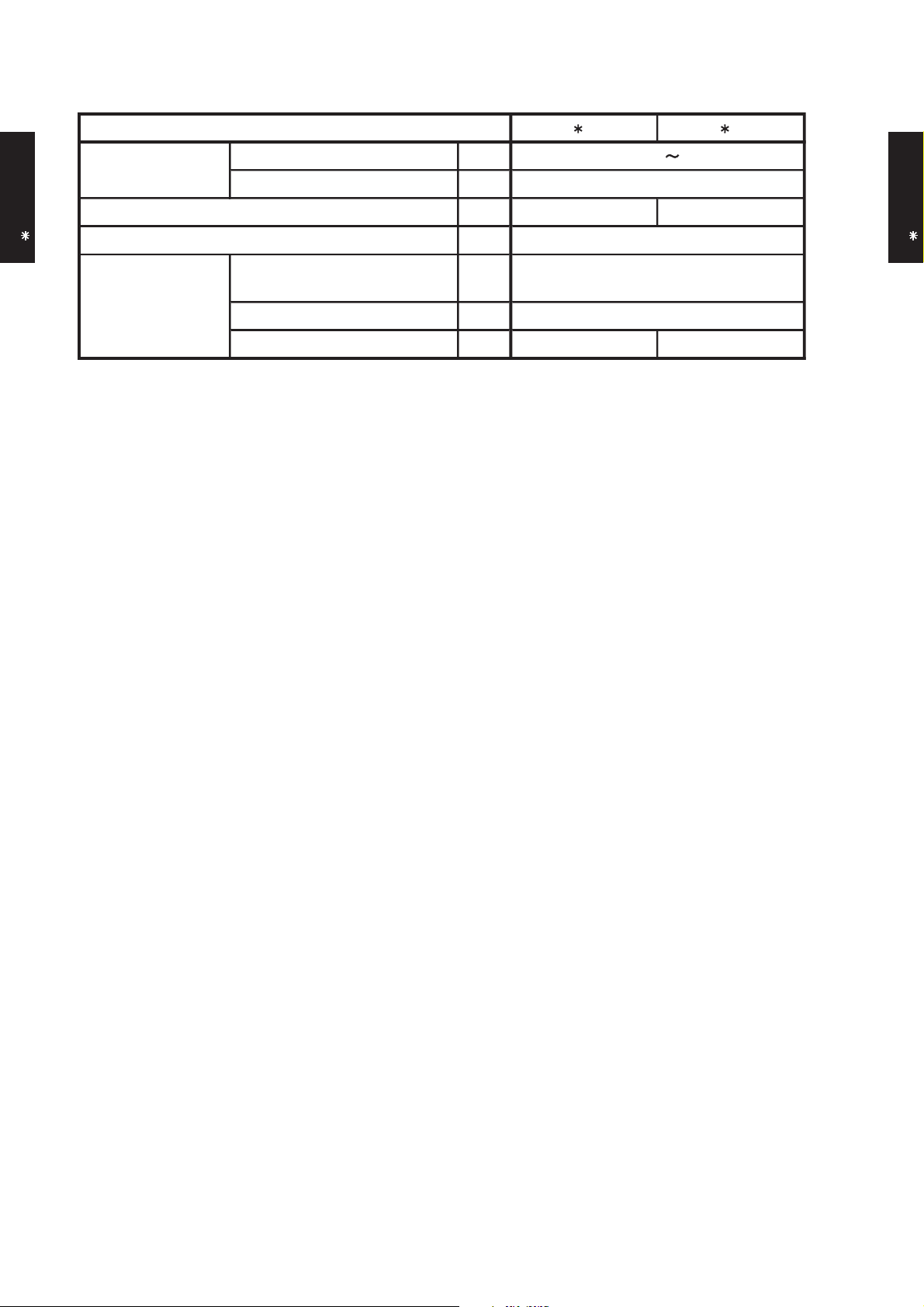
9. ELECTRIC CHARACTERISTICS
AO 18L2 AO 24L2
Main fuse (Circuit breaker)
current
mm
2
Model name
Max. operating current
Starting current
Power supply
*1) Wiring Spec.
2305010253.5
Voltage V
Frequency Hz
A 9.7 12.2
OUTDOOR UNIT
AO 18-24L2
A
OUTDOOR UNIT
AO 18-24L2
A
Power cable
*2)Limited wiring length m 37 29
*1) Wiring Spec.
Selected Sample
(Selected based on Japan Electrotechnical Standard and Codes Committee E0005)
*2) Limited Wiring length :
This is the wiring length in case voltage descent is less than 2%.
When the wiring length becomes long, please select the wiring of a more larger diameter.
- (02 - 14) -
Page 97

10. SAFETY DEVICE
Current fuse (NEAR THE TERMINAL TO
POWER SUPPLY )
OFF : 150±5°C
ON : 96±15°C
OFF : 120°C
ON : 85°C
OFF : 4.2±0.10MPa
ON : 3.2±0.15MPa
25A 250V
Protection form
Model
Current fuse (PCB)
5A 250V
3.15A 250V
Circuit protection
OUTDOOR UNIT
AO 18-24L2
Fan motor protection Thermal protector
Compressor protection Thermal protector
Refrigerrant circuit protection Pressure switch
AO 18L2 AO 24L2
OUTDOOR UNIT
AO 18-24L2
- (02 - 15) -
 Loading...