

Page 1
SPLIT TYPE ROOM AIR CONDITIONER
AIR
UNIT A
UNIT B
b
a
H
H
H
INSTALLATION INSTRUCTION
SHEET
(PART NO. 9373856023)
For authorized service personnel only.
This installation instruction sheet describes how to install the outdoor unit only. To install the indoor unit, refer to the installation instruction sheet included with
the indoor unit.
DANGER
WARNING
CAUTION
The basic installation work procedures are the same as conventional refrigerant models.
However, pay careful attention to the following points:
1 Since the working pressure is 1.6 times higher than that of conventional refrigerant models, some of the piping and
installation and service tools are special. (See the table below.)
Especially, when replacing a conventional refrigerant model with a new refrigerant R410A model, always replace the
conventional piping and flare nuts with the R410A piping and flare nuts.
2 Models that use refrigerant R410A have a different charging port thread diameter to prevent erroneous charging with
conventional refrigerant and for safety. Therefore, check beforehand. [The charging port thread diameter for R410A is
1/2 UNF 20 threads per inch.]
3 Be more careful that foreign matter (oil, water, etc.) does not enter the piping than with refrigerant models. Also, when
storing the piping, securely seal the openings by pinching, taping, etc.
4 When charging the refrigerant, take into account the slight change in the composition of the gas and liquid phases, and
always charge from the liquid phase side whose composition is stable.
Special tools for R410A
Tool name
Gauge manifold
Charge hose
Vacuum pump
Gas leakage detector
Copper pipes
It is necessary to use seamless copper pipes and it is desirable that the amount of
residual oil is less than 40 mg/10 m. Do not use copper pipes having a collapsed,
deformed or discolored portion (especially on the interior surface). Otherwise,
the expansion valve or capillary tube may become blocked with contaminants.
As an air conditioner using R410A incurs pressure higher than when using
conventional refrigerant, it is necessary to choose adequate materials.
Thicknesses of copper pipes used with R410A are as shown in the table. Never
use copper pipes thinner than that in the table even when it is available on
the market.
This mark indicates procedures which, if improperly performed, are most likely to result in the death of or
serious injury to the user or service personnel.
This mark indicates procedures which, if improperly performed, might lead to the death or serious injury of
the user.
This mark indicates procedures which, if improperly performed, might possibly result in personal harm to
the user, or damage to property.
This air conditioner uses new refrigerant HFC (R410A).
Pressure is high and cannot be measured with a conventional gauge. To prevent erroneous mixing of other
refrigerants, the diameter of each port has been changed.
It is recommended the gauge with seals –0.1 to 5.3 MPa (–76 cmHg to 53 kgf/cm
3.8 MPa (–76 cmHg to 38 kgf/cm
To increase pressure resistance, the hose material and base size were changed.
A conventional vacuum pump can be used by installing a vacuum pump adapter.
Special gas leakage detector for HFC refrigerant R410A.
2
) for low pressure.
Contents of change
2
) for high pressure. –0.1 to
Thicknesses of Annealed Copper Pipes (R410A)
Pipe outside diameter
6.35 mm (1/4 in.)
9.52 mm (3/8 in.)
12.70 mm (1/2 in.)
15.88 mm (5/8 in.)
19.05 mm (3/4 in.)
Thickness
0.80 mm
0.80 mm
0.80 mm
1.00 mm
1.20 mm
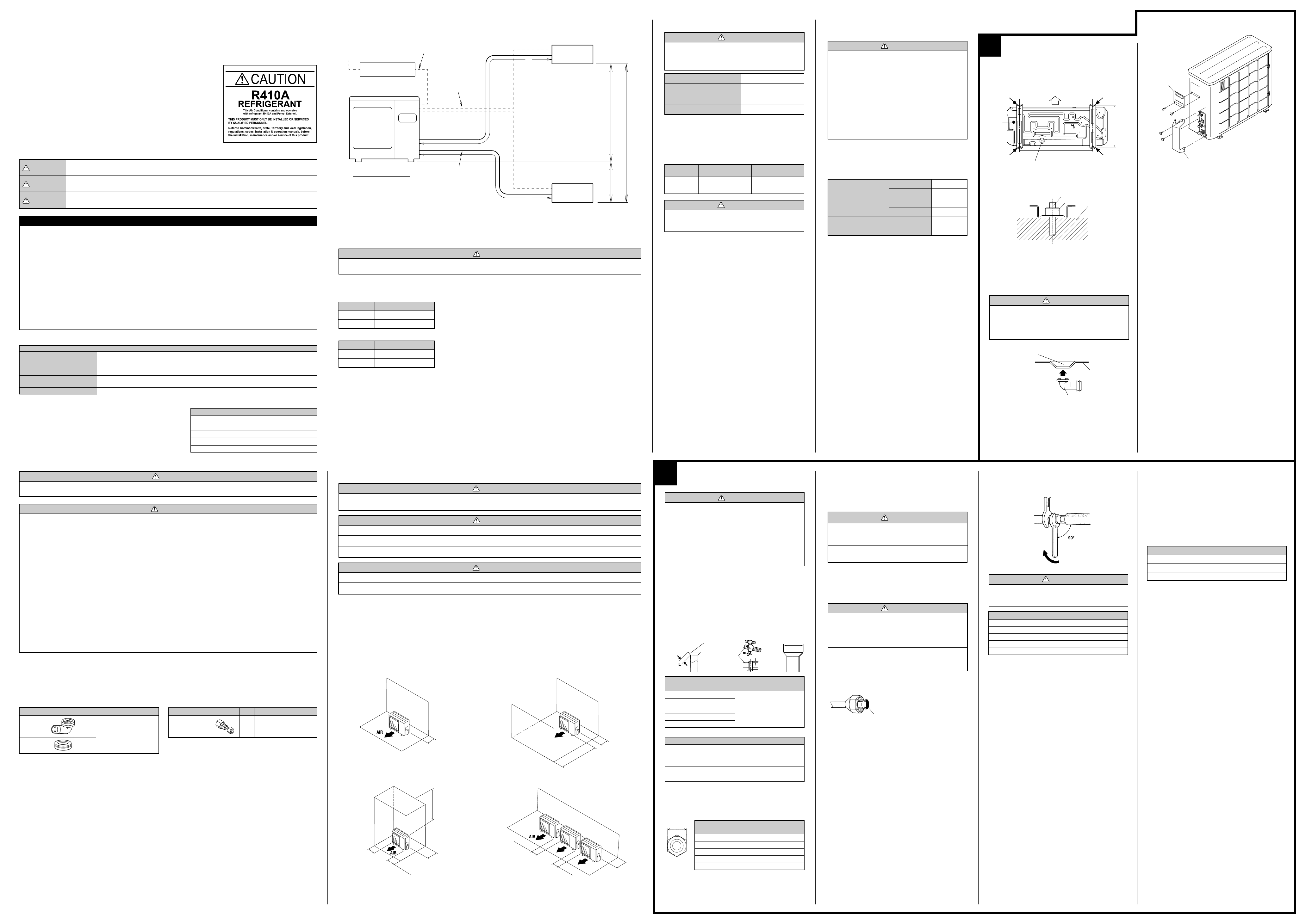
SYSTEM LAYOUT
Layout example for the indoor units and outdoor unit
7 – 12
7 – 12
*1
/14 – 18
*1
/14
Power cord
Connection cord
Refrigerant pipe
INDOOR UNITS
CAUTION
Power source
220-240 V ~ 50 Hz
Circuit breaker
OUTDOOR UNIT
1. CONNECTABLE INDOOR UNIT CAPACITY TYPE
If the total capacity of the connected indoor units, an error will be displayed and the units will not operate. (For information on
error displays, refer to the installation instruction sheets included with the indoor units.)
• To install an indoor unit, refer to the installation instruction sheet included with the indoor unit.
• At least three indoor units must be connected to the outdoor unit.
18 Model
Outdoor port
A
B
24 Model
Outdoor port
A
B
*1 When connecting models 7–12 to the outdoor unit, the included adapter is necessary. (For more information, refer to “2-4 HOW TO USE ADAPTER”.)
Connectable model name
7 – 12
Connectable model name
7 – 12
2. LIMITATION OF REFRIGERANT PIPING LENGTH
CAUTION
The total maximum pipe lengths and height difference of
this product are shown in the table.
If the units are further apart than this, correct operation
cannot be guaranteed.
Total max. length (a+b) 30 m (98 ft)
Max. length for each indoor unit
(A or B)
Max. height difference (H) 10 m (33 ft)
Min. length for each indoor unit
(A or B)
*2 Additional refrigerant charging is not necessary.
20 m (66 ft)
5 m (16 ft)
*2
3. SELECTING PIPE SIZES
The diameters of the connection pipes differ according to the capacity of
the indoor unit.
Refer to the following table for the proper diameters of the connection
pipes between the indoor and outdoor units.
Capacity of
indoor unit
7 – 12 ø9.52 (0.8) ø6.35 (0.8)
14 – 18 ø12.7 (0.8) ø6.35 (0.8)
Gas pipe size
(thickness) [mm]
CAUTION
Operation cannot be guaranteed if the correct combination of pipes, valves, etc., is not used to connect the indoor and outdoor units.
Liquid pipe size
(thickness) [mm]
4. HEAT INSULATION AROUND CONNECTION
PIPES REQUIREMENTS
CAUTION
Install heat insulation around both the gas and liquid pipes.
Failure to do so may cause water leaks.
Use heat insulation with heat resistance above 120 °C. (Reverse cycle model only)
In addition, if the humidity level at the installation location
of the refrigerant piping is expected to exceed 70%, install
heat insulation around the refrigerant piping. If the expected humidity level is 70-80%, use heat insulation that
is 15 mm or thicker and if the expected humidity exceeds
80%, use heat insulation that is 20 mm or thicker.
If heat insulation is used that is not as thick as specified,
condensation may form on the surface of the insulation.
In addition, use heat insulation with heat conductivity of
0.045 W/(m·K) or less (at 20 °C).
Connect the connection pipes according to “2 CONNECTING THE PIPING” in this installation instruction sheet.
5. ELECTRICAL REQUIREMENT
• Electric wire size and fuse capacity:
Power supply cord (mm2)
Connection cord (mm
Fuse capacity (A)
••
• Install the disconnect device with a contact gap of at least 3 mm nearby
••
the units.
••
• Always make the air conditioner power supply a special branch circuit
••
and provide a special breaker.
••
• Always use H07RN-F or equivalent as the power supply cord and the
••
connection cord.
MAX. 4.0
MIN. 3.5
MAX. 2.5
2
)
MIN. 1.5
OUTDOOR UNIT 25
INDOOR UNIT 10
INSTALLATION PROCEDURE
1
1. OUTDOOR UNIT PROCESSING
(1) Outdoor unit to be fasten with bolts at the four places indicated by the
arrows without fail.
Drain
cap
(2) Fix securely with bolts on a solid block. (Use 4 sets of commercially
available M10 bolt, nut and washer.)
(3) Since the drain water flows out of the outdoor unit during heating
operation, install the drain pipe and connect it to a commercial 16 mm
hose. (Reverse cycle model only)
(4) When installing the drain pipe, plug all the holes other than the drain
pipe mounting hole in the bottom of the outdoor unit with putty so
there is no water leakage. (Reverse cycle model only)
When the outdoor temperature is 0 °C or less, do not use
the accessory drain pipe and drain cap. If the drain pipe
and drain cap are used, the drain water in the pipe may
freeze in extremely cold weather. (Reverse cycle model
only)
OUTDOOR UNIT
INSTALLATION
Bottom
Drain pipe mounting place
Drain pipe mounting hole
Air flow
603 mm (23-23/32")
Bolt
CAUTION
Nut
Drain pipe
Block
Base
Remove outdoor unit terminal cover and valve cover.
Terminal cover
343 mm (13-1/2")
Valve cover
DANGER
Never touch electrical components immediately after the power supply has been turned off. Electrical shock may occur. After
turning off the power, always wait 5 minutes or more before touching electrical components.
WARNING
1 For the room air conditioner to operate satisfactorily, install it as outlined in this installation instruction sheet.
2 Connect the indoor unit and outdoor unit with the room air conditioner piping and cords available standards parts. This
installation instruction sheet describes the correct connections using the installation set available from our standard
parts.
3 Installation work must be performed in accordance with national wiring standards by authorized personnel only.
4 Also, do not use an extension cord.
5 Do not turn on the power until all installation work is complete.
6 Do not purge the air with refrigerants but use a vacuum pump to vacuum the installation.
7 There is not extra refrigerant in the outdoor unit for air purging.
8 Use a vacuum pump for R410A exclusively.
9 Using the same vacuum pump for different refrigerants may damage the vacuum pump or the unit.
0 Use a clean gauge manifold and charging hose for R410A exclusively.
A If refrigerant leaks while work is being carried out, ventilate the area. If the refrigerant comes in contact with a flame, it
produces a toxic gas.
••
• Be careful not to scratch the room air conditioner when handling it.
••
••
• After installation, explain correct operation to the customer, using the operating manual.
••
••
• Let the customer keep this installation instruction sheet because it is used when the room air conditioner is serviced or moved.
••
STANDARD PARTS
The following installation parts are furnished. Use them as required.
Name and Shape
Drain pipe
Drain cap
Q’ty
For outdoor unit drain piping
work
1
[Heat & Cool model (Reverse
cycle) only]
1
Use
Name and Shape
Adapter assy
12.7 mm / 9.52 mm
Q’ty
For use when connecting
models 7–12 to outdoor port B
1
Use
SELECTING THE MOUNTING POSITION
WARNING
Select installation locations that can properly support the weight of the indoor and outdoor units. Install the units securely so
that they do not topple or fall.
CAUTION
1 Do not install where there is the danger of combustible gas leakage.
2 Do not install the unit near heat source of heat, steam, or flammable gas.
3 If children under 10 years old may approach the unit, take preventive measures so that they cannot reach the unit.
WARNING
1 Install the unit where it will not be tilted by more than 5˚.
2 When installing the outdoor unit where it may exposed to strong wind, fasten it securely.
Decide the mounting position with the customer as follows:
(1) Install the outdoor unit in a location which can withstand the weight of the unit and vibration, and which can install horizontally.
(2) Provide the indicated space to ensure good airflow.
(3) If possible, do not install the unit where it will be exposed to direct sunlight.
(If necessary, install a blind that does not interfere with the airflow.)
(4) Do not install the unit near a source of heat, steam, or flammable gas.
(5) During heating operation, drain water flows from the outdoor unit.
Therefore, install the outdoor unit in a place where the drain water flow will not be obstructed. (Reverse cycle model only)
(6) Do not install the unit where strong wind blows or where it is very dusty.
(7) Do not install the unit where people pass.
(8) Install the outdoor unit in a place where it will be free from being dirty or getting wet by rain as much as possible.
(9) Install the unit where connection to the indoor unit is easy.
••
• When there are obstacles at the back side.
••
100 mm
or more
••
• When there are obstacles at the back, side(s), and top.
••
••
• When there are obstacles at the back and front sides.
••
100 mm
or more
600 mm
or more
••
• When there are obstacles at the back side with the installation of
••
more than one unit.
2
CONNECTING THE PIPE
CAUTION
1 Do not use mineral oil on flared part. Prevent mineral
oil from getting into the system as this would reduce
the lifetime of the units.
2 While welding the pipes, be sure to blow dry nitrogen
gas through them.
3 The maximum lengths of this product are shown in the
table. If the units are further apart than this, correct
operation can not be guaranteed.
1. FLARING
(1) Cut the connection pipe to the necessary length with a pipe cutter.
(2) Hold the pipe downward so that cuttings will not enter the pipe and
remove the burrs.
(3) Insert the flare nut (always use the flare nut attached to the indoor
and outdoor units respectively) onto the pipe and perform the flare
processing with a flare tool.
Use the special R410A flare tool, or the conventional flare tool.
Check if [L] is flared uniformly
and is not cracked or scratched.
Die
A
Pipe
Pipe outside diameter
6.35 mm (1/4 in.)
9.52 mm (3/8 in.)
12.70 mm (1/2 in.)
15.88 mm (5/8 in.)
19.05 mm (3/4 in.)
Pipe outside diameter
6.35 mm (1/4 in.)
9.52 mm (3/8 in.)
12.70 mm (1/2 in.)
15.88 mm (5/8 in.)
19.05 mm (3/4 in.)
When using conventional flare tools to flare R410A pipes, the dimension
A should be approximately 0.5 mm more than indicated in the table (for
flaring with R410A flare tools) to achieve the specified flaring. Use a thickness gauge to measure the dimension A.
Dimension A
Flare tool for R410A, clutch type
Dimension B
0 to 0.5
9.1
13.2
16.6
19.7
24.0
(mm)
0
(mm)
-0.4
2. BENDING PIPES
The pipes are shaped by your hands. Be careful not to collapse them.
Do not bend the pipes in an angle more than 90°.
When pipes are repeatedly bend or stretched, the material will harden,
making it difficult to bend or stretch them any more. Do not bend or stretch
the pipes more than three times.
CAUTION
1 To prevent breaking of the pipe, avoid sharp bends.
Bend the pipe with a radius of curvature of 150 mm or
over.
2 If the pipe is bent repeatedly at the same place, it will
break.
3. CONNECTION PIPES
Outdoor unit
(1) Detach the caps and plugs from the pipes.
(3) Attach the connection pipe.
(4) When the flare nut is tightened properly by your hand, use a torque
wrench to finally tighten it.
Holding spanner
Body side
Torque wrench
CAUTION
Hold the torque wrench at its grip, keeping it in the right
angle with the pipe, in order to tighten the flare nut
4. HOW TO USE ADAPTER (Connection ports of
outdoor unit)
• When using the ADAPTER, be careful not to overtighten the nut, or the
smaller pipe may be damaged.
• Apply a coat of refrigeration oil to the threaded connection port of the
outdoor unit where the flare nut comes in.
• Use appropriate wrenches to avoid damaging the connection thread by
overtightening the flare nut.
• Apply wrenches on both of flare nut (local part), and ADAPTER to tighten
them.
Adapter tightening torque
Adapter type Tightening torque
ø12.7 mm / ø9.52 mm 50 to 62 [N·m] (500 to 620 kgf·cm)
ø6.35 mm / ø9.52 mm 14 to 18 [N·m] (140 to 180 kgf·cm)
ø12.7 mm / ø15.88 mm 50 to 62 [N·m] (500 to 620 kgf·cm)
correctly.
CAUTION
1 Be sure to apply the pipe against the port on the in-
door unit and outdoor unit correctly. If the centering is
improper, the flare nut cannot be tightened smoothly. If
B
the flare nut is forced to turn, the threads will be damaged.
2 Do not remove the flare nut from the indoor unit pipe
until immediately before connecting the connection
pipe.
(2) Centering the pipe against port on the indoor unit, turn the flare nut
with your hand.
To prevent gas leakage, coat the flare
surface with alkylbenzene oil (HAB).
Do not use mineral oil.
Flare nut Tightening torque
6.35 mm (1/4 in.) dia.
9.52 mm (3/8 in.) dia.
12.70 mm (1/2 in.) dia.
15.88 mm (5/8 in.) dia.
19.05 mm (3/4 in.) dia.
14 to 18 N·m (140 to 180 kgf·cm)
33 to 42 N·m (330 to 420 kgf·cm)
50 to 62 N·m (500 to 620 kgf·cm)
63 to 77 N·m (630 to 770 kgf·cm)
100 to 110 N·m (1000 to 1100 kgf·cm)
600-1000 mm*
100-300 mm*
250 mm or more
(Service space)
If the space is larger than that is stated, the condition will be the
*
same as that there are no obstacles.
300 mm
or more
250 mm
or more
250 mm
or more
300 mm
or more
Width across flats
Pipe outside
diameter
6.35 mm (1/4 in.)
9.52 mm (3/8 in.)
12.70 mm (1/2 in.)
15.88 mm (5/8 in.)
19.05 mm (3/4 in.)
Width across flats
of Flare nut
17 mm
22 mm
26 mm
29 mm
36 mm
- Continued on back -
Page 2
5. VACUUM
L
N
POWER
1
2
3
A
1
2
3
B
1
2
3
1
2
3
EARTH
220-240 V
50 Hz/1ø
NL1
(L)2(N)
31
(L)2(N)
3
UNIT A UNIT B POWER
13
2
(N)
13LN
2
(N)
(1) Remove the cap, and connect the gauge manifold and the vacuum
pump to the charging valve by the service hoses.
(2) Vacuum the indoor unit and the connecting pipes until the pressure
gauge indicates –0.1 MPa (–76 cmHg).
(3) When –0.1 MPa (–76 cmHg) is reached, operate the vacuum pump
for at least 30 minutes.
(4) Disconnect the service hoses and fit the cap to the charging valve to
the specified torque.
(5) Remove the blank caps, and fully open the spindles of the 2-way
and 3-way valves with a hexagon wrench [Torque: 6~7 N·m (60 to
70 kgf·cm)].
(6) Tighten the blank caps of the 2-way valve and 3-way valve to the
specified torque.
Tightening torque
Blank cap
Charging port cap
Outdoor unit
Service hose
with valve core
6.35 mm (1/4 in.)
9.52 mm (3/8 in.)
12.70 mm (1/2 in.)
15.88 mm (5/8 in.)
19.05 mm (3/4 in.)
Connecting pipe
Cap
20 to 25 N·m (200 to 250 kgf·cm)
20 to 25 N·m (200 to 250 kgf·cm)
25 to 30 N·m (250 to 300 kgf·cm)
30 to 35 N·m (300 to 350 kgf·cm)
35 to 40 N·m (350 to 400 kgf·cm)
10 to 12 N·m (100 to 120 kgf·cm)
Blank cap
3-way valve
Charging port
Gauge manifold
LO
HI
Vacuum pump
Service hose
Hexagon wrench
Use a 4 mm
hexagon wrench.
CAUTION
1 Do not purge the air with refrigerants, but use a vacuum
pump to vacuum the installation! There is no extra refrigerant in the outdoor unit for air purging!
2 Use a vacuum pump and gauge manifold and charg-
ing hose for R410A exclusively. Using the same vacuum
for different refrigerants may damage the vacuum pump
or the unit.
3 Charging of additional refrigerant (R410A) according
to the piping length is unnecessary.
6. GAS LEAKAGE INSPECTION
CAUTION
1 After connecting the piping, check the all joints for gas
leakage with gas leak detector.
2 When inspecting gas leakage, always use the vacuum
pump for pressure. Do not use nitrogen gas.
7. RECHARGING THE REFRIGERANT
CAUTION
1 When moving and installing the air conditioner, do not
mix gas other than the specified refrigerant (R410A)
inside the refrigerant cycle.
2 When charging the refrigerant R410A, always use an
electronic balance for refrigerant charging (to measure the refrigerant by weight).
3 When charging the refrigerant, take
into account the slight change in the
composition of the gas and liquid
phases, and always charge from the
liquid phase side whose composition is stable.
4 Add refrigerant from the charging valve after the com-
pletion of the work.
5 If the units are further apart than the maximum pipe
length, correct operation can not be guaranteed.
Gas
R410A
Liquid
3
POWER
WARNING
1 The rated voltage of this product is 220-240 V A.C. 50 Hz.
2 Before turning on verify that the voltage is within the
198 V to 264 V range.
3 Always use a special branch circuit and install a spe-
cial receptacle to supply power to the air conditioner.
4 Use a special branch circuit breaker and receptacle
matched to the capacity of the air conditioner.
(Install in accordance with standard.)
5 Perform wiring work in accordance with standards so
that the air conditioner can be operated safely and positively.
6 Install a leakage special branch circuit breaker in ac-
cordance with the related laws and regulations and electric company standards.
CAUTION
1 The power source capacity must be the sum of the air
conditioner current and the current of other electrical
appliances. When the current contracted capacity is insufficient, change the contracted capacity.
2 When the voltage is low and the air conditioner is diffi-
cult to start, contact the power company the voltage
raised.
4
ELECTRICAL WIRING
WARNING
1 Before starting work, check that power is not being
supplied to the indoor unit and outdoor unit.
2 Match the terminal board numbers and connection
cord colors with those of the outdoor unit.
Erroneous wiring may cause burning of the electric
parts.
3 Connect the connection cords firmly to the terminal
board. Imperfect installation may cause a fire.
4 Always fasten the outside covering of the connection
cord with the cord clamp. (If the insulator is chafed,
electric leakage may occur.)
5 Always connect the ground wire.
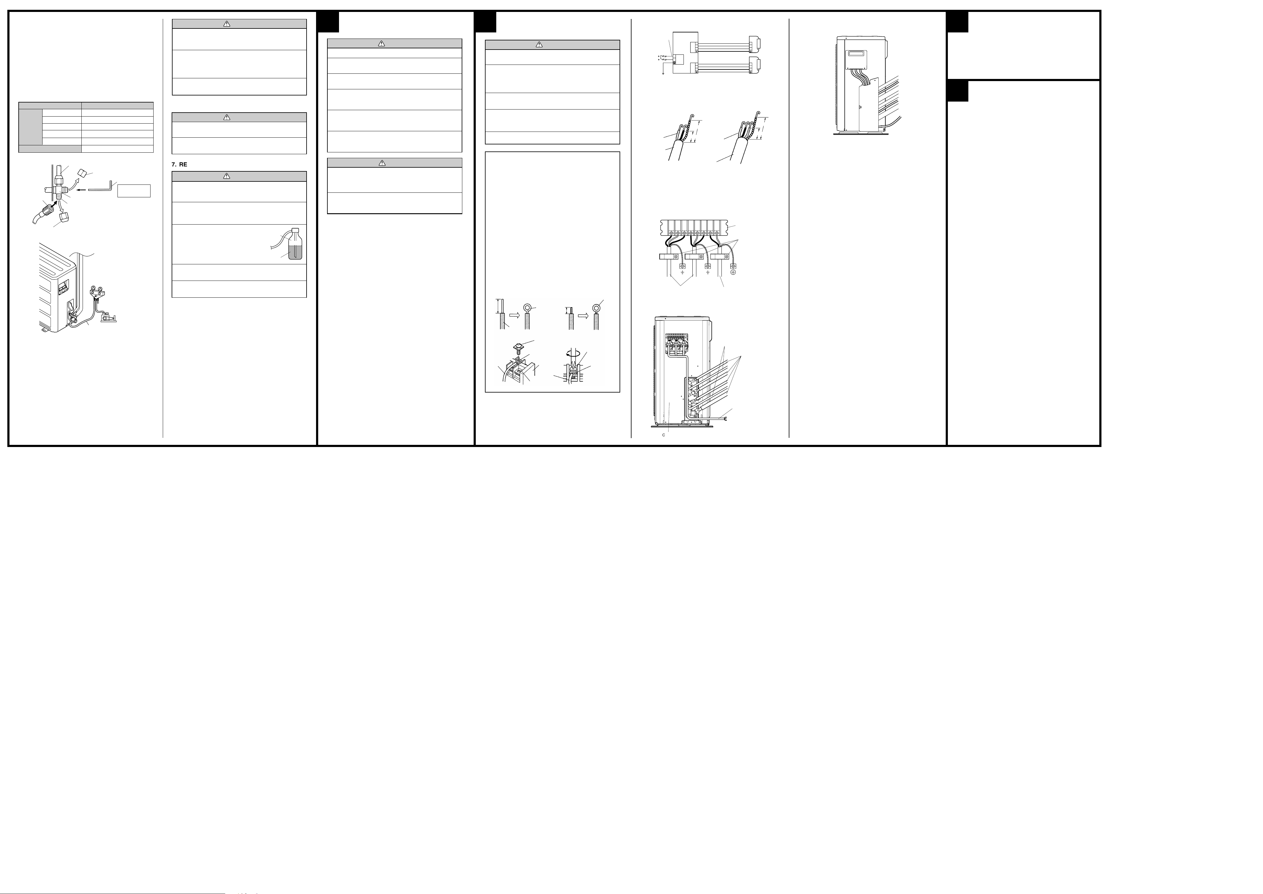
HOW TO CONNECT WIRING TO THE
TERMINALS
A. For solid core wiring (or F-cable)
(1) Cut the wire end with a wire cutter or wire-cutting pliers, then strip
the insulation to about 25 mm to expose the solid wire.
(2) Using a screwdriver, remove the terminal screw(s) on the terminal
board.
(3) Using pliers, bend the solid wire to form a loop suitable for the
terminal screw.
(4) Shape the loop wire properly, place it on the terminal board and
tighten securely with the terminal screw using a screwdriver.
B. For strand wiring
(1) Cut the wire end with a wire cutter or wire-cutting pliers, then strip
the insulation to about 10 mm to expose the strand wiring.
(2) Using a screwdriver, remove the terminal screw(s) on the terminal
board.
(3) Using a round terminal fastener or pliers, securely clamp a round
terminal to each stripped wire end.
(4) Position the round terminal wire, and replace and tighten the
terminal screw using a screwdriver.
Strip 25 mm
Wire
A. Solid wire
Insulation
Loop
Screw with
special washer
Round terminal
Terminal
board
Wire
B. Strand wire
Strip 10 mm
Screw with
special washer
Round
terminal
Round
terminal
1. CONNECTION DIAGRAMS
Power cord
Connection cord
A
Connection cord
B
2. CORD PREPARATION
Keep the earth wire longer than the other wires.
60 mm
20 mm
(Insulator)
(Sheath)
Power cord
60 mm
20 mm
(Insulator)
(Sheath)
Connection cord
3. OUTDOOR UNIT
(1) Connect the power supply cord and the connection cord to terminal.
(2) Fasten the power supply cord and connection cord with cord clamp.
Terminal block
Cord clamp
Connection cord
(3) Pass the connection cord and power cord through the hole of the 3-
way valve bracket and run them to the outside of the cabinet.
Power cord
Connection cord
Connection pipe
(4) Install the valve cover and terminal cover as shown. Pass the power
cord and connections cords through the valve cover when wiring them.
5
The test run method may be different for each indoor unit that is connected. Refer to the installation instruction sheet included with each indoor unit.
6
Explain the following to the customer in accordance with the operating
manual:
(1) Starting and stopping method, operation switching, temperature
adjustment, timer, air flow adjustment, and other remote control unit
operations.
(2) Air filter removal and cleaning.
(3) Give the operating manual and installation instruction sheet to the
customer.
TEST RUNNING
CUSTOMER GUIDANCE
Terminal block
Cabinet
Power cord
PART NO. 9373856023
 Loading...