

Page 1

SPLIT TYPE
ROOM AIR CONDITIONER
WALL MOUNTED
Models
Indoor unit Outdoor unit
ASH9LSBCW AOH9LFBC
ASH12LSBCW AOH12LFBC
type
CONTENTS
SPECIFICATIONS . . . . . . . . . . . . . . . . . . . . . . . . . . . . . . . . . . . . . . . . 1
DIMENSIONS . . . . . . . . . . . . . . . . . . . . . . . . . . . . . . . . . . . . . . . . . . . 2
REFRIGERANT SYSTEM DIAGRAM . . . . . . . . . . . . . . . . . . . . . . . . 3
CIRCUIT DIAGRAM . . . . . . . . . . . . . . . . . . . . . . . . . . . . . . . . . . . . . . 4
ERROR CONTENTS . . . . . . . . . . . . . . . . . . . . . . . . . . . . . . . . . . . . .
DISASSEMBLY ILLUSTRATION . . . . . . . . . . . . . . . . . . . . . . . . . . . . 9
PARTS LIST . . . . . . . . . . . . . . . . . . . . . . . . . . . . . . . . . . . . . . . . . . . 12
STANDARD ACCESSORIES
. . . . . . . . . . . . . . . . . . . . . . . . . . . . .
14
5INDOOR PRINTED CIRCUIT BOARD CIRCUIT DIAGRAM . . . . .
6OUTDOOR PRINTED CIRCUIT BOARD CIRCUIT DIAGRAM . . .
7
Page 2
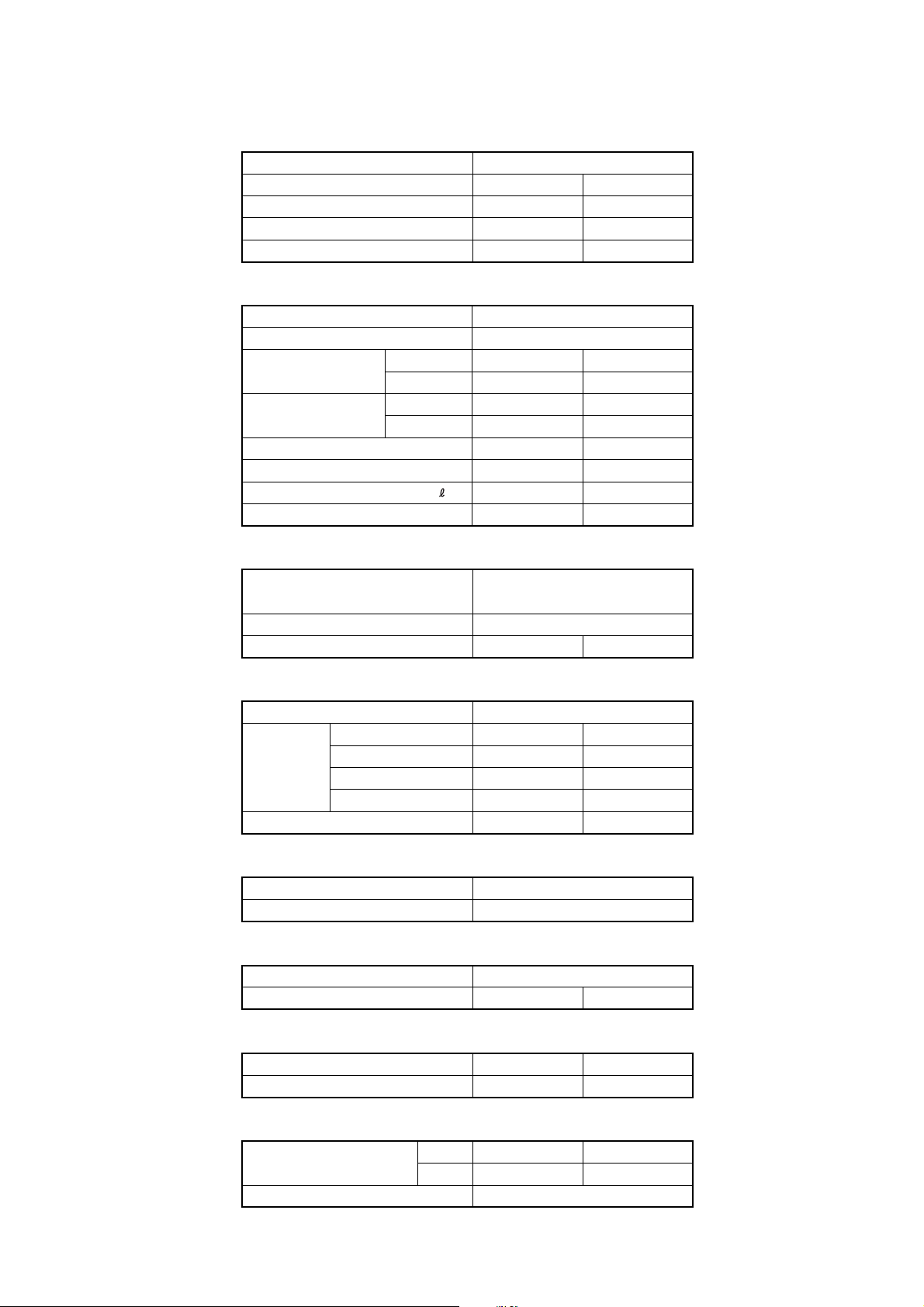
SPECIFICATIONS
TYPE
INDOOR UNIT
OUTDOOR UNIT
COOLING CAPACITY
HEATING CAPACITY
(kW) 3.50
(kW)
COOL & HEAT INVERTER
ASH9LSBCW
AOH9LFBC
2.60
3.60
ELECTRICAL DATA
POWER SOURCE (V) 230
FREQUENCY (Hz)
RUNNING CURRENT
INPUT WATTS
E.E.R.
COP HEATING
MOISTURE REMOVAL
AIR CIRCULATION-Hi (m /hr)
(kW/kW)
(kW/kW)
COOLING 4.3
(A)
HEATING
COOLING 0.92
(kW)
HEATING
COOLING
( /hr)
3
3.0
3.8
0.62
0.82
4.19
4.39
1.3
50
COMPRESSOR
TYPE
DISCRIMINATION DA 89 X 1F - 20F
REFRIGERANT R410A (g) 1,050950
Hermetic type, 4 pole, 3 phase,
DC inverter motor, Rotary
ASH12LSBCW
AOH12LFBC
4.80
5.6
1.23
3.80
3.90
1.8
C 635 H 670C 595 H 645
FAN MOTOR
POWER SOURCE (V) 230
HI-SPEED (r.p.m.) C 1,300 H 1,390
INDOOR
UNIT
OUTDOOR UNIT (r.p.m.) C 830 H 830C 840 H 840
MED-SPEED (r.p.m.) C 1,120 H 1,200
LO-SPEED (r.p.m.) C 950 H 1,000
QUIET (r.p.m.) C 700 H 760
DIMENSIONS
INDOOR UNIT
OUTDOOR UNIT
H x W x D (mm)
H x W x D (mm)
275 x 790 x 215
540 x 790 x 290
WEIGHT
INDOOR UNIT
OUTDOOR UNIT
GROSS / NET (kg)
GROSS / NET (kg)
NOISE LEVEL
INDOOR UNIT
OUTDOOR UNIT
(dB) C 43 H 43
(dB) C 47 H 49
C 42 H 42
C 47 H 48
REFRIGERANT (R410A)
Pipe Length
FULL CHARGE AMOUNT
ADDITIONAL REFRIGERANT
15 m 950 g 1,050 g
20 m 1,050 g 1,150 g
20 g / m
C 1,370 H 1,440
C 1,150 H 1,200
C 950 H 1,000
C 700 H 760
12 / 9
42 / 3839 / 35
2005.01.31 1
Page 3
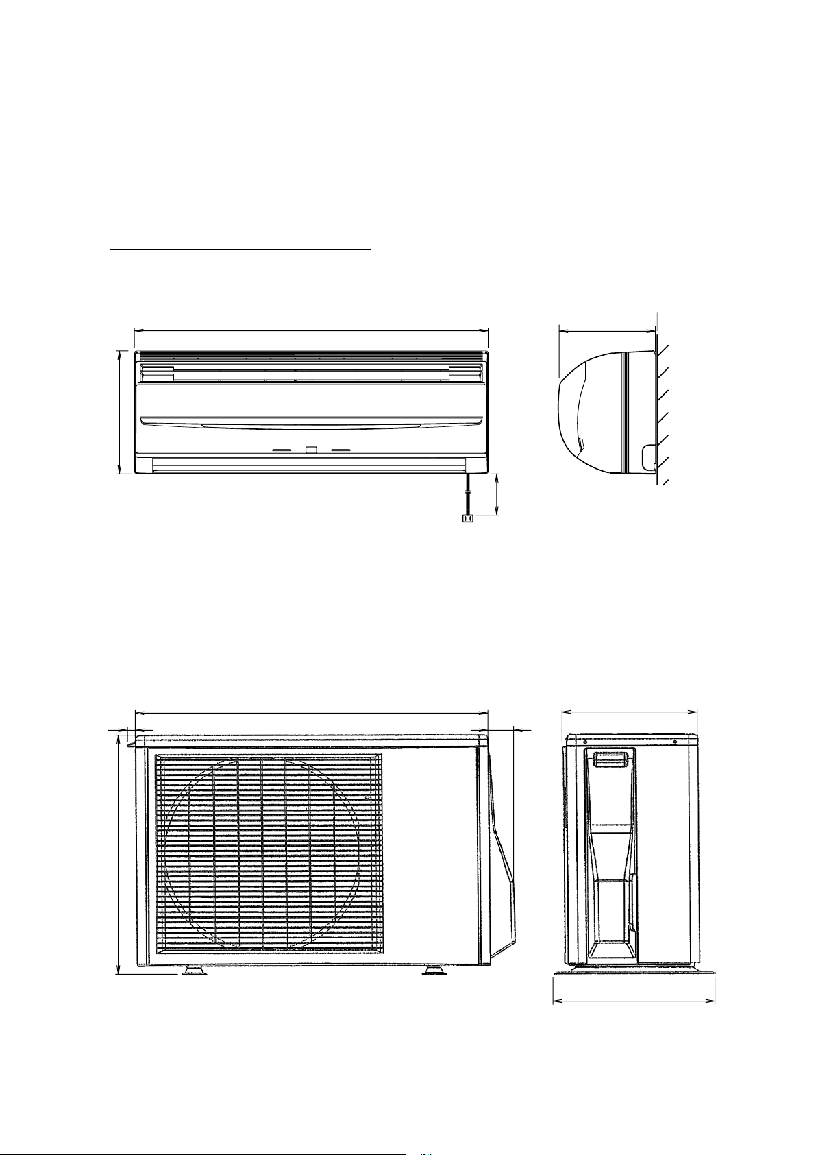
DIMENSIONS
Models : ASH9LSBCW / AOH9LFBC
ASH12LSBCW / AOH12LFBC
790
275
(unit : mm)
215
2,000
17
540
790
290
56
( 353 )
2005.02.18 2
Page 4
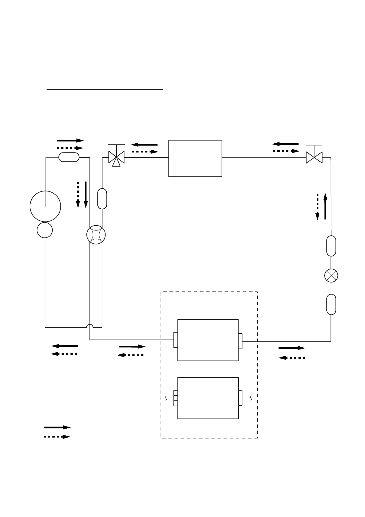
REFRIGERANT SYSTEM DIAGRAM
Models : ASH9LSBCW / AOH9LFBC
ASH12LSBCW / AOH12LFBC
Muffler
Compressor
3-Way
valve
Muffler
4-Way valve
Heat exchanger
( INDOOR )
2-Way
valve
Strainer
Expansion valve
Cooling
Heating
Heat exchanger
( OUTDOOR )
AOH9LFBC
(2Pass)
AOH12LFBC
(4Pass)
Strainer
2005.02.01 3
Page 5
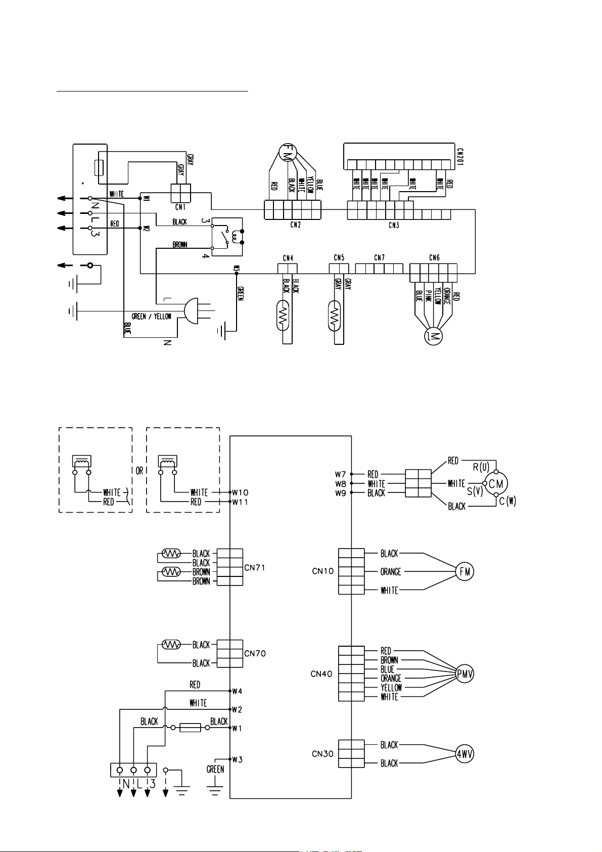
CIRCUIT DIAGRAM
Models : ASH9LSBCW / AOH9LFBC
ASH12LSBCW / AOH12LFBC
INDOOR UNIT
Terminal
Thermal Fuse
102 C
2
1
2
1
Power
Fan Motor
6
6
Power
Relay
Display Board
10
11
9
5
5
5
1
2
3
4
1
2
3
4
6
7
10
11
9
5
6
7
8
1
2
3
4
5
6
7
8
1
2
3
4
1
2
3
4
Controller PCB
1
2
3
4
5
1
1
1
2
2
2
3
4
5
Test
5
1
2
3
4
OUTDOOR UNIT
Reactor Reactor
Thermistor (Discharge Pipe)
Thermistor (pipe)
Thermistor (outdoor temp.)
Thermistor
(room temp.)
Thermistor
(pipe temp.)
Stepping
Motor
PCB (MAIN)
Compressor
1
1
2
2
3
3
1
1
1
2
2
3
3
4
4
1
1
2
2
3
3
1
2
2
3
3
4
4
5
5
1
1
2
2
3
3
4
4
5
5
6
6
Fan Motor
Expansion
Valve
Fuse 250V20A
Terminal
2005.01.31 4
1
1
2
2
3
3
4-Way
Valve Assy
Page 6

INDOOR PCB CIRCUIT DIAGRAM
Models :
TERMINAL BOARD
N
L
3
UL1015
AWG22
W3
GREEN
GREEN
E
ASH9LSBCW
ASH12LSBCW
BLUE
WHITE
RED
W2
W1
VA1
470V
R60 330K
<1/2W>
C1 0.1 <F>
C3
0.01
<F>
L1
1.3A
9.0mH
18
10
C2
0.01
<F>
R2 2.2
<5W>
I C7
H I 2002 ( or GK30431 )
BROWN
3.15A
- 250V
R1 2.2
<5W>
BLACK
K1
D I 12D1
F1
FAN MOTOR
GREEN / YELLOW
E
D1
GS I B460L
R12
1.0K
<1/2W>
14
POWER SOURCE
230V
50Hz
F2
2.5A - 250V
C4
+
100/
420V
EN / UV
I C2
TNY266P
SSSSS
A
F M
VM
5
D
BP
8
32
7
R3 100K
<2W>
C5
0.01
D2 1NH42
PS2561-1
<L>
4
4
3
1
C6
0.1
<F>
1
4
5
2
3
CONTROLLER PCB ASSY
ASH9LSBCW : K02DR-0410HSE-C1
ASH12LSBCW : K02DR-0411HSE-C1
I C 1
uPD780024ASGB-X52-8ET-A
25
P10
17
18
10
20
26
27
21
34
52
19
36
46
45
44
14
38
15
16
23
22
39
37
AN I 0
P23
P24
24
P11
AN I 1
VDD0
VDD1
AVREF
AVDD
GND0
9
AGND
GND1
RESET
P47
P25
P01
I NTP1
P41
P40
P75
BUZ
P20
P03
P21
P22
P12
AN I 2
P13
AN I 3
P70
P02
I NTP2
X1
33
P42
P35
P57
P56
P55
P54
P53
P52
P51
P50
P00
I NTP0
P46
P45
P44
P43
P34
P36
XT1
XT2
P74
P73
P72
P71
X2
I C
32
X1
8.38MHz
31
28
C35
0.1
<F>
47
12
8
7
6
5
4
3
2
1
35
51
50
49
48
11
13
30
29
43
42
41
40
JP1
R46 1.0K
<1/8W>
5V
C28
0.1
<F>
C31
0.1
<F>
R42
100K
<1/8W>
6
5V
R36
10K
<1/8W>
5
R55 1.0K <1/8W>
R38 1.0K
<1/8W>
R40 1.0K
<1/8W>
5V
I C11
S80842
2 3
VDD
1
OUT
5V
R45
10K
<1/8W>
I C13-6
11
R30 330 <1/8W>
R29 330 <1/8W>
R28 330 <1/8W>
R27 330 <1/8W>
C25
R37 47
1000P
<1/8W>
<R>
12V
9
2
15
143
4 13
12
8
I C13-1
R44
10K
<1/8W>
NC
GND
SW1
5V
I C13-2
I C13-3
I C13-4
I C13-5
R39
10K
<1/8W>
(1%)
R41
49.9K
<1/8W>
(1%)
4
C26
100/
16V
5V
R56
10K
<1/8W>
1
I C12
S-93C46ADFJ
1
CS
2
SK
3
D I
TEST
7
NC
5V
VCC
GND
+
12V
16
DO
K 1
JM19
JP3
C27
0.01
<B>
CN6
53325-0510
5V
8
4
6
5
C36
0.1
<F>
5V
12V
CN4 2P-SAN
CN4-1 BLACK
CN4-2 BLACK
CN5-1 GRAY
CN5-2 GRAY
CN5 2P-SCN
CN3
S07B-ZR-3.4
CN6-1 RED
CN6-2 ORANGE
CN6-3 YELLOW
CN6-4 PINK
CN6-5 BLUE
ROOM TEMPERATURE THERMISTOR
PIPE TEMPERATURE THERMISTOR
INDICATOR PCB
K02CB-0300HSD-D0
5V
D208 SLR-325 <ORG>
D205 SLR-325 <GRN>
D204 SLR-325 <GRN>
D201 SLR-325 <RED>
C201
0.1 <F>
LOUVER
5V
C202
47/10V
5V
+
R201
47
<1/4W>
I C201
GP 1UM261RK
WHITE
WHITE
WHITE
WHITE
WHITE
RED
WHITE
CN201
JB20-11HG
CN201-1
CN201-2
CN201-3
CN201-4
CN201-5
CN201-6
CN201-7
CN201-8
CN201-9
CN201-10
CN201-11
M
Jumper wire configurations
Switch Function ON/Linked OFF/Open
JM1 Custom code A B
JM2 Auto restart enable disable
VCC
OUT
GND
I C3
1
2
C9
330/
25V
R5
2M
<1/4W>
15V
+
I C4
78M15
3
C10
0.1
<F>
O
I
G
2
R4 18K
<1/8W>
THERMAL FUSE
102
GRAY
GRAY
T1
ETS19AB1P8AG
6
10
D4
D2FL20U
4
D3
20V
D1FL20U
JP7
1
+
C7
100/35V
2
5
1
7
13.5V
C12
+
330/
25V
I C5
TL431 I LP
CN1
C11 0.01 <F>
C
A
R7
1.0K
<1/8W>
12V
I C6
D5
7805
D1F60
I
C15
+
330/
25V
C14
0.01
R8 47K
<B>
<1/8W>
REF
R53,R54
10K <1/8W>
O
G
C16
0.1
<F>
R9
34K
<1/8W>
(1%)
R10
8.25K
<1/8W>
(1%)
5V
5V
C19
C18
+
0.1
10/
<F>
25V
C17
+
330/
25V
5V
5V
C20
0.01
<B>
C21
0.01
<B>
7
C22
Q4
DTC124EUA
C23
1000P
<R>
TEST
RED
BLACK
WHITE
YELLOW
BLUE
BZ
PKM13EPY-4000-TF01
CN7
BS5P-SHF-1AA
CN7-1
CN7-2
CN7-3
CN7-4
CN7-5
CN2-6
CN2-4
CN2-3
CN2-2
CN2-1
12V
TIMER SHORT
CLOCK
DATA-OUT
DATA-I N
CN2
53426-9920
Q2
DTC124EUA
R43 10K
<1/8W>
B Z
5V
CUSTOM CODE SWITCHING
JM1
JM2
AUTO RESTART
VM
15V
C24
A
100/
16V
R23 6.8K <1/4W>
R26 820
<1/4W>
(1%)
+
A
A
Q1
DTC124EUA
R49 - R52, R47,R48
10K <1/8W> x 6
15V
R25 1.0K
<1/4W>
(1%)
15V
15V
R22
4.7K
<1/8W>
R13
10K
<1/8W>
I C10
PS2561-1
<L>
4
3
I C9
PS2561-1
<L>
1
2
R14 1.0K
<1/8W>
R15 1.0K <1/8W>
I C13-7
10
5V
R24 330
1
<1/8W>
2
5V
R21
10K
<1/8W>
4
3
R20 1.0K
<1/8W>
2005.01.31 5
Page 7

CONTROLLER PCB ASSY
AOH9LFBC : K04DT-0400HUE-C1
AOH12LFBC : K04DT-0401HUE-C1
O U TDOOR P C B C I R C U I T D I A G R A M
Models :
AOH9LFBC
AOH12LFBC
CONTROLLER PCB ASSY
AOH9LFBC : K04DT-0400HUE-C1
AOH12LFBC : K04DT-0401HUE-C1
POWER SOURCE
230V
50Hz
4-WAY VALVE
FAN MOTOR
F M
EXPANSION VALVE
DISCHARGE TEMPERATURE THERMISTOR
PIPE TEMPERATURE THERMISTOR
OUTDOOR TEMPERATURE THERMISTOR
2005.01.31 6
M
F201
20A - 250V
W201
UL1015
AWG14
BLACK
N
L
EARTH
SERIAL
UL1015 AWG20
RED
CN30
B2P3-VH-B-C
BLACK
CN10
BH3P5-VH-B
WHITE
BLACK
UL1015
AWG14
UL1015 AWG14
WHITE
UL1015 AWG16
GREEN
BLACK
BLACK
BLACK
ORANGE
WHITE
RED
BROWN
BLUE
ORANGE
YELLOW
WHITE
CN40
B6B-XARK-1-A
RED
BLACK
BLACK
BROWN
BROWN
BLACK
BLACK
W1
B
VA2
470V
<TNR>
W2
W3
W4
B
CN71
B04B-PASK-1
WHITE
CN70
B03B-PASK-1
WHITE
REACTOR
12A 18mH
W10
W11
RED
WHITE
AWG14
AWG14
R1
K1
DW12D-0
13
-
14
12
+
I C103-4
uPC324
R147
R150
PFC / 58P
R151
R148
195K <RN-1/2W> x 4
D111
DAN
217U
2 1
2
-12V
R144
22K
(1%)
C123
R152
2200P
4.7K
<B>
(1%)
12V
SO / I C80-2
V4-AC / I C80-3
V4-DC / I C80-4
PR / I C80-5
AC FAN / I C80-6
AOY12LFBC
R584 22K
R585
1.0K
ZXL / 37P
S I / 48P
C20
0.022
<F>
B
ZPR0RCH400
12V
C21
0.047
<B>
C4
0.01
<E>
C5
0.01
<E>
VA1 470V
<TNR>
SA1
RA-302M
C1 1.0
<LE>
B
B
HY I C 1
14
GK-30434
10 5 4 3 2
5V
18
SO / I C80-2
C6 1.0
<LE>
L1
SC-10-55JH
5V
R23
27K
1
R21
10K
R20 1.0K
R22 1.0K
JM32
1 2
3
K30
G5NB-1A
K3
G5N-1A
2
431
R40
R41
R42
R43
1.5K x 4
R93 R92 R90R91
C71
0.1
<F>
C72
0.1
<F>
V4-AC / I C80-3
JM30
4
12V
AC FAN / I C80-6
EPV3/44P
EPV4/43P
EPV2/42P
EPV1/45P
5V
10K x 4
TE / 5P
TD / 4P
TA / 6P
R149
4.7K
(1%)
D80
SLR-332
<RED>
Model Changing
AOY9LFBC
JM101
JM102
JM103
TEST
TAUX / 25P
TTXD / 60P
TRXD / 61P
TMODE / 18P
TAUX3 / 21P
TCK / 62P
/ TRES / 19P
1
2
3
1
2
3
4
5
6
1
2
3
4
1
2
3
CR30
RE1201
C80
1.8
<DS401185>
5V
L70
BL02Rn1
C75
0.1
<F>
TD62064
2
7
9
16
4
5
12
13
R71
4.75K
(1%)
R72
6.65K
(1%)
R73
38.3K (1%)
JM31
CR80
RE1202
I C40
O1
O2
O3
O4
GND1
COM1
GND2
COM2
GND3
NC1
GND4
NC2
I 1
I 2
11
I 3
14
I 4
10
15
R77
10K
12V
12V
3
6
1
8
C40
0.1
<F>
MD0 / 1P
MD1 / 64P
MD2 / 63P
TEST / 59P
R75
10K
R76
10K
C73
0.1
<F>
B
W6
W5
PR / I C80-5
R132
2.2K
2
Q101
DTC114EUA
15V
3
D110
1
DAN217U
3
9
10
R145
22K
(1%)
R146 47K
(1%)
C124
2200P
<B>
E2CS / 41P
E2SK / 40P
E2DI / 39P
R80
2.2K
JM101
JM102
JM103
TEST
R582 10K
R583 1.0K
D100
D15XB60
2
3
D101
D15XB60
2
3
B
ORANGE
UL1015
B
15V
-12V
3
C118
1000P
1
<B>
R159
4.7K
C129
1000P
<B>
R143
47K
(1%)
-
8
+
I C104-3
uPC324
12V
C580
0.1
<F>
R581 10K
AWG14
2
1
R131
100K
(1%)
+
-
+
-
D105
DAN217U
I C80
M54523
1C
2C
3C
4C
5C
6C
7C
COM
1
4
1
4
R400 - R405
0.15 <2W> (1%) x 6
3
9
-
8
10
+
I C103-3
uPC324
5V
R160
68K
(1%)
I C105-1
LM2903
R161
1.5K(1%)
R137 10K (1%)
D109
RB751V
R140 10K
(1%)
R139 10K
(1%)
I C570
BR93LC46
1
CS
2
SK
3
D I
6
NC
LED / 30P
1B
SO / 32P
2B
V4-AC / 27P
3B
V4-DC / 29P
4B
5B
PR / 31P
AC FAN / 28P
6B
7B
E
CN580
5V
B10B-PASK-1
WHITE
1
2
3
4
5
6
7
8
9
10
R126
100K
(1%)
I C103-1
uPC324
2
3
R127 10K (1%)
R128 10K (1%)
R129 100K (1%)
I C103-2
R130
uPC324
100K
6
(1%)
-
7
5
+
C117
1000P
<B>
5V
R162
68K (1%)
3
+
1
2
-
6
-
5
+
R136
10K (1%)
R138 10K
(1%)
6
-
7
5
+
D108 RB751V
I C104-2
uPC324
5V
8
VCC
4
DO
NC
7
5
GND
R570
10K
TAUX
TTXD
TRXD
TMODE
TAUX3
TCK
/ TRES
/ TICS
FLASH
WRITING
-
+
R163
10K (1%)
ZXH / 36P
I C105-2
LM2903
7
R135
10K (1%)
C570
0.1
<F>
R122
10K
1
R123
10K (1%)
C121
47P
<CH>
D107
RB751V
R133
10K
(1%)
R134
10K
(1%)
I C104-1
uPC324
2
3
R141
10K
(1%)
FAN I N / 17P
FAN PWM / 2P
PFC SW / 35P
CT / 3P
TEST / 59P
PFS / 58P
TTXD / 60P
TAUX3 / 21P
CP-POS / 47P
V4-AC / 27P
AC FAN / 28P
V4-DC / 29P
LED / 30P
PR / 31P
SO / 32P
I PM-TRIP / 33P
E2CS / 41P
EPV2 / 42P
EPV4 / 43P
EPV3 / 44P
I PM-CR / 9P
DCV / 8P
ACV / 7P
TE / 5P
TA / 6P
TD / 4P�@�@�@�@
F101
15A - 250V <ATLCR>
3 3
1 1
2 2
D115
DAN217U
R166
10K (1%)
R116
15K (1%)
R118
10K (1%)
R119
10K
(1%)
C111
4700P
<B>
R164
22K
R168 22K R169 22K
-
1
+
I C104-4
uPC324
13
-
14
12
+
C500
0.1
<F>
R121 220K
(1%)
I C102-1
BA10339
5
+
4
-
C113
2700P
<B>
5V
D114
DAN217U
R117
22K
(1%)
C125
0.1
<F>
C131
0.1
<F>
17
16
35
59
58
60
21
34
47
27
28
29
30
31
32
33
57
41
42
43
44
10
22
2
R115
22K (1%)
7
+
6
I C102-2
BA10339
C135
0.01 <F>
R165
22K
+
C126
2.2/50V
C132
+
2.2/
50V
R504
10K
I C500
MB90460
P63
P62
2
P46
P12
3
P50
P37
P36
P40
MD2
P11
P26
P02
P03
P04
P05
P06
P07
P10
C
P20
P21
P22
P23
P57
9
P56
P55
8
7
P54
5
P52
6
P53
4
AGND
P51
X0
X1
X500
8.0MHz
<EF0MC>
R120 10K
(1%)
I C101
TC74HC00AF
1
1
2
2
3
3
4
4
5
5
6
6
7
7
5V
R112
10K
(1%)
1
C110
0.1 <F>
C127
2.2/50V
+
C133
+
2.2/
50V
VCC
56
11
AVCC
25
P00
26
P01
40
P17
36
P13
37
P14
38
P15
39
P16
12
AVR
45
P24
46
P25
50
P30
51
P31
52
P32
53
P33
54
P34
55
P35
14
P60
15
P61
18
MD0
20
MD1
64
P44
63
P43
P42
62
P41
61
1
P45
19
RSTX
48
P27
13
24
GND
4923
GND
14
14
13
13
12
12
11
11
10
10
9
9
8
8
I C102-4
BA10339
11
+
10
-
C128
0.1
<F>
5V
R500
10K
C502
0.1
<F>
5V
C106
0.1
<F>
13
5V
1
3
C134
0.1
<F>
C501
4.7/50V
D102
1NH42
R103
100
<1/2W>
Q100
GT30JI21
R102
47K
R109 22
<1/4W>
I C100 TA8316
R167
10K
(1%)
I C102-3
BA10339
+
14
-
C136
0.01
<F>
D112
2
DAN217U
5V
1 2
3
R502
1.0K
R503
10K
C503
+
0.1
<F>
C103 0.1 <HCP>
R108 47
<1/4W>
2
VCC
1
GATI N
5
6
SO
S I
7
D I
4
NC
3
GND
PFCSW / 35P
PFCEN / 14P
PFC-TRIP / 46P
195K <RN-1/2W> x 2
5V
5V
1 2
9
R113 4.7K
(1%)
8
R114
R111 10K
15K
CT / 3P
D113
DAN217U
ACV / 7P
JM500
TAUX / 25P
E2SK / 40P
ZXH / 36P
ZXL / 37P
E2DI / 39P
EPV1 / 45P
PFC-TRIP / 46P
U / 50P
X / 51P
V / 52P
Y / 53P
W / 54P
Z / 55P
PFCEN / 14P
TMODE / 18P
MD1 / 64P
MD2 / 63P
TCK / 62P
TRXD / 61P
MD0 / 1P
/ TRES / 19P
S I / 48P
R561
1.0K
C561
0.01
<F>
15A - 250V <ATLCR>
C100 750 / 385V
C101 750 / 385V
+ + +
15V
C105
0.1
L100
<F>
C104
+
4.7/
50V
D106
DAN217U
R110
3
6.8K
+
C108
2.2/50V
C109
+
2.2/
50V
15V
C119
0.1
<F>
C120
0.1
<F>
-12V
5V
R560
100K
RESET
F100
C102 750 / 385V
R104
220K
<2W>
POW_GND
BL02Rn1
DCV-F
R106
R105
R107
3.83K
(1%)
POW_GND
C107
0.1
<F>
DCV / 8P
I C103_PASS CON
C115
0.1
<F>
2
3
VDD
NC
4
1
OUT GND
I C560
S80842
F4
BET
3.15A - 250V
DCV-F
D200
R203 330K
C205 0.1 <F>
U / 50P
V / 52P
W / 54P
X / 51P
Y / 53P
Z / 55P
I PM-TRIP / 33P
C219
1000P
<B>
I PM-CR / 9P
Q300
DTC114EUA
CP-POS / 47P
C300
100P
<CH>
15V
C116
0.1
<F>
-12V
15V
C130
0.1
<F>
15V
C112
0.1
<F>
DCV
FH2
FH1
U1JU44
+
R202 330K
C204 47/35V
R204 - R209
390 x 6
R220
1.0K
R339
R83
27K
I C104_PASS CON
Q50
2SC4236
I C105_PASS CON
R50 2.4
<1/2W>
POW_GND
I C102_PASS CON
L300 47uH
<ELC0607>
R200 39
<1/2W>
D201
U1JU44
+
R201 330K
C202 47/35V
C203 0.1 <F>
R219 1.0K
2200P
5V
2 1
3
C320
5V
0.15
<EC
QB>
R334
10K (1%)
R337
100K
10K (1%)
(1%)
3
1
2
I C302-1
1
LM2903
5V
R95
1.0K
R96
3
4.7K
1
2
Q80
2SC2412K
<BQ>
DCV-F
R51 220K
<2W>
2
1
3
D50
15V
D202
U1JU44
+
C200 47/35V
C201 0.1 <F>
5V
R218
10K
C206
C207
C208
<B>
x 6
D301
DAN217U
R327
22K
(1%)
R335 - R336
10K (1%) x 2
2
-
3
+
C339
0.01
<F>
R340
10K
(1%)
15V
R81
22K
7
I C302-2
LM2903
R52 1.0K
<RS-3W>
C51 20P
<B>
R53
100
<1W>
D51
RD5.6ES
<B2>
R54
D1FL20U
330
<1/4W>
C209 0.1 <F>
I PM-G
D302
RB751V
C311
1000P
<B>
R338
4.7K
(1%)
C85
4.7/
50V
6
-
5
+
C52
0.047
<ECQB>
C53
100/
16V
COMPRESSOR
C. M.
C221 0.1 <F>
C211 0.1 <F>
C212 0.1 <F>
C210 0.1 <F>
C215
C216
R328
1.0K (1%)
R331
47K (1%)
R333
10K
(1%)
C330
1000P
<B>
15V
D304
+
DAN217U
C86
C87
C84
470P
330P
0.1
<B>
<B>
<F>
16
15
13
12
10
9 8
D52
D1FL20U
+
EMI FILTER
BLACK BLACK
WHITE WHITE
RED RED AWG16
+
C220 47 / 35V
C222 1.0 <B>
D203 ZP1027
C214
2200P
<B>
C213
0.022
C217
<F>
I PM-G
R329 47K (1%)
2
-
1
3
+
I C300-1
LM258
5
+
7
6
-
I C300-2
LM258
D60 D2FL20U
D61 D1FL20U
C65
+
220/
35V
D63
D1FL20U
1
2
3
6
7
3
C66
0.1
<F>
D303
DAN217U
C61
470/
25V
221 1
3
T60
JPZ200
1-172132-1
R223
R222
R221
10 <1/2W> x 3
( INTLLIGENT
POWER MODULE )
1
VCC
2
COM
3
I N
I N
4
I N
5
6
VFO
7
CFOD
8
CSC
9
I N
10
VCC
11
VB
12
VS
13
I N
14
VCC
15
VB
16
VS
I N
17
18
VCC
19
VB
20
VS
I C200
FSB20CH60
I PM-G
R330 4.7K (1%)
R332 4.7K (1%)
15V
C306
0.1
<F>
C305
0.1
<F>
-12V
R309
5.76K
(1%)
R60
+
10K
D62
D1FL20U
C64 0.1 <F>
D64 - D67
D1FL20U x 4
AWG16
U
B BB
W7 W8 W9
21
NU
22
NV
23
NW
24
U
25
V
26
W
27
P
R210
1.0K
I C300_PASS CON
U V
R305R306
195K
<RN-1/2W> x 6
R310
143
(1%)
12V
123
C60
+
220/
16V
C68
+
0.1
<F>
AWG16
U V
R304 R303
I C60
TA7805
I
G
C67
100/
35V
-12V
V
I PM-G
W
R301
R302
O
15V
+
W
R211
R212
R213
R214
R215
R216
R217
0.15
<1W>
x 7
POW_GND
C63
100/
35V
W
DCV
C218 0.1 <HCP>
R307 195K
<RN-1/2W>
R308 195K
<RN-1/2W>
R311
8.66K
(1%)
5V
C62
+
100/
16V
Page 8

ERROR CONTENTS
Self-diagnosis function table (Flashing LED Display)
Applicable model : ASH9LSBCW, ASH12LSBCW
* Detailed Trouble Display (secondary level) can be indicated by pressing Test Operation button.
Trouble Display (primary) Detailed Trouble Display (by Test Button)
Error
Serial signal Normal 1 sec
error blinking
Indoor unit 0.5sec 0.1sec
thermistor 2 times blinking
Operation
Timer Error
Serial reverse signal error
at operation start up
Signal reverse signal error
during operation
Serial forward signal error
at operation start up
Serial forward signal error
during operation
Indoor temperature
thermistor open
Operation
0.1sec 0.5sec
blinking 2 times
0.1sec 0.5sec
blinking 3 times
0.1sec 0.5 sec
blinking 4 times
0.1sec 0.5sec
blinking 5 times
0.1sec 0.5sec
blinking 2 times
error
Pipe thermistor
open or short
0.1sec 0.5sec
blinking 3 times
Timer
Detailed Error Item
When a signal is not read continuously for 10 secs
from power relay ON immediately after operation starts
>>Cooling 0 code transmission, automatic reset
When a signal is not read for 20 secs thereafter
>>Trouble display continues and power relay OFF
>>Permanent stop
When a signal is not read continuously for 10 secs
from power relay ON immediately after operation starts
>>Cooling 0 code transmission, automatic reset
When a signal is not read for 20 secs thereafter
>>Trouble display continues and power relay OFF
>>Permanent stop
Normal Serial Forward Signal can not be
received more than 10 secs
>>Releases when it becomes normal
Normal Serial Forward Signal can not be
received more than 10 secs ( after receiving
effective forward transfer signal)
>>Releases when it becomes normal
Thermistor detection value is open when
AC plug is inserted
IndoorIndoorIndoorIndoorIndoor OutdoorOutdoorOutdoor
>>Releases when value becomes normal
Thermistor detection value is open or short
when AC plug is inserted
Outdoor unit 0.5sec 0.1sec
thermistor 3 times blinking
error
Indoor unit 0.5sec 0.1sec
control error 4 times blinking
Discharge thermistor
open or short
Heat exchanger
thermistor open
Outdoor temperature
thermistor open or short
Forced automatic SW
welded
Main relay welded
Power interruption error
0.1sec 0.5sec
blinking 2 times
0.1sec 0.5sec
blinking 3 times
0.1sec 0.5sec
blinking 4 times
0.1sec 0.5sec
blinking 2 times
0.1sec 0.5sec
blinking 3 times
0.1sec 0.5sec
blinking 4 times
>>Releases when value becomes normal
Thermistor detection value is open or short
>>Outdoor unit stops
Releases when it becomes normal
Thermistor detection value is open
>>Outdoor unit stops
Releases when it becomes normal
Thermistor detection value is open or short
>>Outdoor unit stops
Releases when it becomes normal
Forced Auto SW is ON for more than
10 secs continuously
>>Error is indicated while it is ON
Normal Operation other than error indication
Serial Reverse Signal is received 1 min.
after Main relay becomes OFF
>>Error is indicated while serial reverse
signal is input on normal operation
Normal operation except error indication
50/60Hz is not detected after 4 secs of
power ON.
2005.02.18 7
>>Error is indicated and unit is stopped
Page 9

Trouble Display (primary) Detailed Trouble Display (by Test Button)
Error
Outdoor unit 0.5sec 0.1sec
Operation
Timer Error
Current trip
Operation
Timer
0.1sec 0.5sec
control error 5 times blinking blinking 2 times
CT abnormal
0.1sec 0.5sec
blinking 3 times
0.1sec 0.5sec
blinking 5 times
0.1sec 0.5sec
blinking 6 times
0.1sec 0.5sec
Indoor fan 0.5sec 0.1sec
Compressor rotation
error
Outdoor unit fan drive
system abnormal
Abnormal lock
motor error 6 times blinking blinking 2 times
Abnormal rotation
0.1sec 0.5sec
blinking 3 times
Detailed Error Item
Current trip error is 2nd time within
start up
>>Permanent stop
Current detection value is 0A for more
than 1 sec when compressor is operated
at more than 56rps
>>Automatic release after 3 min. ST
Compressor location detection error (incl.
failed start up) for 3 times
>>Permanent stop
When outdoor fan abnormal fan motor
duty abnormal operated 5 times
Outdoor
>>Permanent stop
Detected rotation is 0 r.p.m. at start up or
at 56 secs after Fan mode is selected
IndoorIndoor OutdoorOutdoorOutdoorOutdoorOutdoorOutdoorOutdoorOutdoor
>>Permanent stop
Detected rotation is 1/3 of target r.p.m. at
start up or at 56 secs after Fan mode is
selected
Refrigerant 0.5sec 0.1sec
cycle error 7 times blinking blinking 2 times
Optional 0.5sec 0.1sec
function 8 times blinking blinking 2 times
Discharge temperature
abnormal
Cooling high pressure
abnormal rise
Active filter voltage
abnormal (3rd time)
0.1sec 0.5sec
0.1sec 0.5sec
blinking 3 times
0.1sec 0.5sec
error
Active filter foltage
abnormal (1st time)
PFC circuit
abnormal
0.1sec 0.5sec
blinking
3 times
0.1sec 0.5sec
blinking 4 times
>>Permanent stop
Discharge Temperature protection
(Discharge temperature is 110degC)
operated 2 times
>>Permanent stop
High pressure rise protection (Outdoor
heat exchanger temperature is 65degC)
operated
>>Comp. OFF (releases after 3min.ST)
Error is indicated while 3 min.ST
Active Filter voltage error operated 3 times
>>Permanent stop
Active Filter Module error or open
detection protection operated
>>Automatic release after 3 min. ST
>>Permanent stop
2005.02.18 8
Page 10

Models : ASH9LSBCW
ASH12LSBCW
DISASSEMBLY ILLUSTRATION
5
53
51
6
5
4
3
1
1
2005.01.31 9
2
7
Page 11

Models : ASH9LSBCW
ASH12LSBCW
236
26
188
48
28
32
52
31
24
29
27
39
37
46
20
43
30
61-2
23
21
61-1
36
32
38
42
33
2005.01.31 10
Page 12

Models : AOH9LFBC
AOH12LFBC
11
43
46
22
21
2
9
40
1
7
42
10
4
3
8
26
41
37
38
27
29
42
5
45
13
15
14
24
18
36
32
19
39
12
17
23
16
2005.01.31 11
25
Page 13

INDOOR UNIT
PARTS LIST
Ref.
No.
1 Air Filter 9309997011
Filter (Electric) 9312153015
2
3 Filter (ION) 9311925033
4
Holder (Filter) 93066020179306602017
Clamper (Grille) 9306755010
5
6 Front Panel Total Assy 9313130107
Intake Grille Assy 9313131067
7
20 Gear-A 9309994003
21 Casing Assy 9312112081
23 Cover (Casing)-B 9311916017
24 Crossflow Fan Assy 9307836015
26 Clamp (Motor) 9310102008
27 Shaft Holder-C Assy 9306628017
28 Drain Hose Assy 9310357019
29 Drain Cap Assy 9304150008
30
Wire Clamper 9311946014
Box (Switch) 9309996014
31
32 Cover (Switch) 9311863014
33 Evaporator Total Assy 9313099015
Joint Pipe Assy 9313104016
36
Description
ASH9LSBCW ASH12LSBCW
9309997011
9312153015
9311925033
9306755010
9313130107
9313131067
9309994003
9312112081
9311916017
9307836015
9310102008
9306628017
9310357019
9304150008
9311946014
9309996014
9311863014
9313099015
9313104016
Part No.
Ord.
Q'ty
37 Insulation (Pipe)-E 9304607007
38
Holder (Evaporator)-L 9309982017
39 Holder (Evaporator)-R 9309983014
42 Air Seal 9310611005
43
Terminal 9701955077
46
Step Motor 9900139025
48 Fan Motor Assy 9601814016
51
Remote Control Unit 9313144012
52
Bracket Panel 9310001004
53 Remote Control Unit Holder 93056420149305642014
61-1 Flow Control Panel-U 9309991033
61-2
Flow Control Panel-Z 9309992030
188
236 Controller PCB Assy 9705656062
Power Cord 9900157012
--- Pipe Temperature Thermistor 9702039042
Room Temperature Thermistor 9700801108
---
--- Indicator PCB Assy 9705039032
When you order parts, please make a photocopy of this page
and fill the number of the parts in the "Order" column.
9304607007
9309982017
9309983014
9310611005
9701955077
9900139025
9601814016
9313144012
9310001004
9309991033
9309992030
9900157012
9705656055
(K02DR-0410HSE-C1) (K02DR-0411HSE-C1)
9702039042
9700801108
9705039032
2005.01.31
12
Page 14

OUTDOOR UNIT
Ref.
No.
1 Fuse Holder
2 Fuse
3 Thermister Holder Pipe
4 Thermistor Spring-A
5 Thermistor Spring
7 Terminal
8 Cord Clamp
9 Cover (Case)
10 Bracket Valve
11 Cover (Switch)
12 Rubber Cushion
13 Inverter Case Assy
15 Nut Special Assy
16 Front Panel
17 Fan Ring
18 Propeller Fan
19 Bracket (Motor) Assy
21 Separator-B
22 Protective Net
23 Base Assy (Painted)
Description
Part No.
AOH9LFBC AOH12LFBC
0501454012
0600382018
313714262805
313728262708
9300089012
9306489038
9307271014
9309913011
9310229026
9310979013
9312680016
9312972029
9313452018
9313806026
9313807016
9313808013
9313990015
9313815011
9313941017
9313987015
0501454012
0600382018
313714262805
313728262708
9300089012
9306489038
9307271014
9309913011
9310229026
9310979013
9312680016
9312972029
9313452018
9313806026
9313807016
9313808013
9313990015
9313815011
9313941017
9313987015
Ord.
Q'ty
24 Top Panel (Painted)
25 Cabinet Left (Painted)
26 Cabinet Right (Painted)
27 3-Way Valve Assy
29 4-Way Valve Assy
32 Compressor Assy
36 Cover (Inverter Case)
37 2-Way Valve Assy
38 Pulse Motor Valve Assy
39 Motor
40 Inverter PCB Assy
41 Expansion Valve Coil
42 Thermistor Assy
43 Thermistor (Outdoor Temp)
45 Solenoid
46 Condenser Total Assy 9314032011
--- Emblem Rear 93126350239312635023
9313989026
9313992019
9313995027
9314022012
9314093012
9314278013
9314507014
9314554018
9314557019
9601859017
9705706019
9900057039
9900148027
9900210038
9970033018
9314107016
When you order parts, please make a photocopy of this page
and fill the number of the parts in the "Order" column.
9313989026
9313992019
9313995027
9314022012
9314093012
9314278013
9314507014
9314554018
9314557019
9601859017
9705706019
9900057039
9900148027
9900210038
9970033018
2005.01.31
13
Page 15

STANDARD ACCESSORIES
Part No.
Name and Shape
ASH9LSBCW, ASH12LSBCW
Wall hook bracket
9312752010
Remote control
unit
9308846099
Remote control
unit holder
9305642014
Battery (penlight)
Cloth tape
Tapping screw (big)
( 4 x 25)
Tapping screw (small)
( 3 x 12)
Air cleaning filter
Air cleaning filter
frame
0600185534
9310519004
0700076046
0700019036
9312153015
9311925033
9306602017
2005.02.01
14
Page 16

0501G2743
 Loading...