

Page 1

SPLIT TYPE
ROOM AIR CONDITIONER
CEILING
Models Indoor unit Outdoor unit
ABG30ABA-W AOG30AMBH
ABG30RBA-W AOG30RMCL
ABY30ABA-W AOY30AMBH
ABY30RBA-W AOY30RMCL
ABT30ABA-W AOT30AMBL
ABT30RBA-W AOT30RMCL
ABG45RGC3W AOG45RCG3L
ABY45RGC3W AOY45RCG3L
ABT45RGC3W AOT45RCG3L
type (50Hz)
AOG30AMBL
AOY30AMBL
ABG54ABA3W AOG54APA3L
ABG54RBA3W AOG54RPA3L
ABY54ABA3W AOY54APA3L
ABY54RBA3W AOY54RPA3L
ABT54ABA3W AOT54APA3L
ABT54RBA3W AOT54RPA3L
CONTENTS
SPECIFICATIONS . . . . . . . . . . . . . . . . . . . . . . . . . . . . . . . . . . . . . . . . 1
OUTLINE AND DIMENSIONS . . . . . . . . . . . . . . . . . . . . . . . . . . . . . . 3
REFRIGERANT SYSTEM DIAGRAM . . . . . . . . . . . . . . . . . . . . . . . . 5
ERROR CONTENTS . . . . . . . . . . . . . . . . . . . . . . . . . . . . . . . . . . . . . 8
CIRCUIT DIAGRAM . . . . . . . . . . . . . . . . . . . . . . . . . . . . . . . . . . . . . 10
INDOOR PRINTED CIRCUIT BOARD CIRCUIT DIAGRAM . . . . 15
REMOTE CONTROL UNIT CODE SWITCHING . . . . . . . . . . . . . . 17
DISASSEMBLY ILLUSTRATION . . . . . . . . . . . . . . . . . . . . . . . . . . . 18
PARTS LIST . . . . . . . . . . . . . . . . . . . . . . . . . . . . . . . . . . . . . . . . . . . 43
2003.05.13
Page 2

2003.05.13
– 1 –
FULL CHARGE AMOUNT
PIPE LENGTH AB_30ABA-W AB_30ABA-W AB_30RBA-W AB_45RGC3W AB_54ABA3W AB_54RBA3W
7.5 m (25 ft)
2,400 g (84.7 oz) 2,500 g (88.2 oz) 2,700 g (95.2 oz) 3,500 g (123.5 oz) 3,600 g (127.0 oz) 3,700 g (130.5 oz)
10.0 m (33 ft) 2,450 g (86.4 oz) 2,550 g (89.9 oz) 2,825 g (99.6 oz) 3,500 g (123.5 oz) 3,600 g (127.0 oz) 3,700 g (130.5 oz)
20.0 m (66 ft) 2,650 g (93.5 oz)
2,750 g (97.0 oz) 3,325 g (117.3 oz) 3,500 g (123.5 oz) 3,600 g (127.0 oz) 3,700 g (130.5 oz)
25.0 m (82 ft) 2,750 g (97.0 oz) 2,850 g (100.5 oz) 3,575 g (126.1 oz) 3,700 g (130.5 oz) 3,800 g (134.0 oz) 3,950 g (139.3 oz)
30.0 m (99 ft) 2,850 g (100.5 oz) 2,950 g (104.1 oz) ----- 3,900 g (137.6 oz) 4,000 g (141.1 oz) 4,200 g (148.2 oz)
40.0 m (132 ft) -----
----- ----- 4,300 g (151.7 oz) 4,400 g (155.2 oz) 4,700 g (165.8 oz)
50.0 m (164 ft) ----- ----- ----- 4,700 g (165.8 oz)
4,800 g (169.3 oz) 5,200 g (183.4 oz)
ADDITIONAL CHARGE 20 g/m (0.23 oz/ft) 20 g/m (0.23 oz/ft)
50 g/m (0.58 oz/ft) 40 g/m (0.46 oz/ft) 40 g/m (0.46 oz/ft) 50 g/m (0.58 oz/ft)
SPECIFICATIONS
TYPE COOLING COOLING
COOLING & HEATING COOLING & HEATING
COOLING
COOLING & HEATING
INDOOR UNIT
ABG30ABA-W ABG30ABA-W ABG30RBA-W ABG45RGC3W ABG54ABA3W ABG54RBA3W
ABY30ABA-W ABY30ABA-W ABY30RBA-W ABY45RGC3W ABY54ABA3W ABY54RBA3W
OUTDOOR UNIT
AOG30AMBL AOG30AMBH AOG30RMCL AOG45RCG3L AOG54APA3L AOG54RPA3L
AOY30AMBL AOY30AMBH AOY30RMCL AOY45RCG3L AOY54APA3L AOY54RPA3L
COOLING CAPACITY
(kW)
8.6 - 8.8 8.6 - 8.8 8.3 - 8.6 12.4 - 12.7 13.9 - 14.1 13.9 - 14.1
HEATING CAPACITY ----- ----- 9.3 - 9.5 13.4 - 13.7 ----- 15.4 - 15.8
POWER SOURCE (V) 220 - 240 380 - 415
FREQUENCY 1 50Hz 3 50Hz
RUNNING
(A)
COOLING 14.7 - 14.5 14.7 - 14.5 15.0 - 14.8 7.5 - 7.5 9.0 - 8.9 9.0 - 8.9
CURRENT
HEATING ----- ----- 13.6 - 13.9 7.5 - 7.5 ----- 9.1 - 9.0
INPUT
(kW)
COOLING 3.2 - 3.3 3.2 - 3.3 3.25 - 3.35 4.35 - 4.45 5.20 - 5.25 5.20 - 5.25
WATTS
HEATING ----- ----- 2.95 - 3.10 4.25 - 4.35 ----- 5.30 - 5.30
E.E.R. (kW/kW)
COOLING 2.69 - 2.67 2.69 - 2.67 2.55 - 2.57 2.85 - 2.85 2.67 - 2.69 2.67 - 2.69
HEATING ----- ----- 3.15 - 3.06 3.15 - 3.15 ----- 2.91 - 2.98
MOISTURE REMOVAL ( /hr) 4 5.5
AIR CIRCULATION (m3/hr) 1,270 1,850 2,100 2,100
ELECTRICAL DATA
COMPRESSOR
FAN MOTOR
DIMENSIONS
TYPE
Hermetic type Hermetic type
2 poles, Induced by condenser
2 poles, 3 phase, Induced by condenser
CODE NH52VNHT NHT52VAAT NH52VNHT CRPQ-0450-TFD ZR72KC-TFD
POWER SOURCE (V) 220 - 240
TYPE MFA-45DZM
INDOOR
HI-SPEED ( r.p.m. ) 850 1,100 1,200
UNIT
MED-SPEED ( r.p.m. ) 750 1,000 1,100
LO-SPEED ( r.p.m. ) 600 850 950
OUTDOOR
TYPE MFB-30DFT MFB-362FT
HI-SPEED ( r.p.m. ) ,730 760 790 770
UNIT
LO-SPEED ( r.p.m. ) 450 470 510 -----
INDOOR UNIT H x W x D 240 x 1,660 x 700
OUTDOOR UNIT (mm) 900 x 900 x 350 1,152 x 940 x 370
WEIGHT
INDOOR UNIT NET / GROSS 61 / 48
OUTDOOR UNIT
(kg) 79 / 91 79 / 91 80 / 92 108 / 122 112 / 126 120 / 134
Notes : • Between 7.5 m and 50 m, when using a connection pipe other than that in the table, charge additional refrigerant with 20 g/m (0.23
oz/ft
)
for 30A Model, 50 g/m (0.58
oz/ft
) for 30R, 54R Models, 40 g/m (0.46
oz/ft
) for 45R, 54A Models as the criteria.
• Additional gas charge is not necessary with pipe length up to 20 m (for 45R, 54A, 54R types), and 7.5 m (for 30A, 30R types).
Page 3
2003.05.13
– 2 –
FULL CHARGE AMOUNT
PIPE LENGTH ABT30ABA-W ABT30RBA-W ABT45RGC3W ABT54ABA3W ABT54RBA3W
7.5 m (25 ft)
2,400 g (84.7 oz) 2,700 g (95.2 oz) 3,500 g (123.5 oz) 3,600 g (127.0 oz) 3,700 g (130.5 oz)
10.0 m (33 ft) 2,450 g (86.4 oz) 2,825 g (99.6 oz) 3,500 g (123.5 oz) 3,600 g (127.0 oz) 3,700 g (130.5 oz)
20.0 m (66 ft) 2,650 g (93.5 oz)
3,325 g (117.3 oz) 3,500 g (123.5 oz) 3,600 g (127.0 oz) 3,700 g (130.5 oz)
25.0 m (82 ft) 2,750 g (97.0 oz) 3,575 g (126.1 oz) 3,700 g (130.5 oz) 3,800 g (134.0 oz) 3,950 g (139.3 oz)
30.0 m (99 ft) 2,850 g (100.5 oz) ----- 3,900 g (137.6 oz) 4,000 g (141.1 oz) 4,200 g (148.2 oz)
40.0 m (132 ft) -----
----- 4,300 g (151.7 oz) 4,400 g (155.2 oz) 4,700 g (165.8 oz)
50.0 m (164 ft) ----- ----- 4,700 g (165.8 oz) 4,800 g (169.3 oz)
5,200 g (183.4 oz)
ADDITIONAL CHARGE 20 g/m (0.23 oz/ft) 50 g/m (0.58 oz/ft)
40 g/m (0.46 oz/ft) 40 g/m (0.46 oz/ft) 50 g/m (0.58 oz/ft)
TYPE COOLING
COOLING & HEATING COOLING & HEATING
COOLING
COOLING & HEATING
INDOOR UNIT ABT30ABA-W ABT30RBA-W ABT45RGC3W ABT54ABA3W ABT54RBA3W
OUTDOOR UNIT AOT30AMBL AOT30RMCL AOT45RCG3W AOT54APA3L AOT54RPA3L
COOLING CAPACITY
(kW)
8.8 8.6 12.7 14.1 14.1
HEATING CAPACITY ----- 9.5 13.7 ----- 15.8
POWER SOURCE (V) 240 415
FREQUENCY 1 50Hz 3 50Hz
RUNNING
(A)
COOLING 15.3 14.8 7.5 8.9 8.9
CURRENT
HEATING ----- 13.9 7.5 ----- 9.0
INPUT
(kW)
COOLING 3.40 3.35 4.45 5.25 5.25
WATTS
HEATING ----- 3.10 4.35 ----- 5.30
E.E.R. (kW/kW)
COOLING 2.59 2.57 2.85 2.69 2.69
HEATING ----- 3.06 3.15 -----
-----
2.98
MOISTURE REMOVAL ( /hr) 4.0 5.5
AIR CIRCULATION (m3/hr) 1,270 1,850 2,100 2,100
ELECTRICAL DATA
COMPRESSOR
FAN MOTOR
DIMENSIONS
TYPE
Hermetic type Hermetic type
2 poles, Induced by condenser 2 poles, 3 phase, Induced by condenser
CODE NH52VNHT CRPQ-0450-TFD ZR72KC-TFD
POWER SOURCE (V) 240
TYPE MFA-45DZM
INDOOR
HI-SPEED ( r.p.m. ) 850 1,100 1,200
UNIT
MED-SPEED ( r.p.m. ) 750 1,000 1,100
LO-SPEED ( r.p.m. ) 600 850 950
OUTDOOR
TYPE MFB-30DFT MFB-362FT
HI-SPEED ( r.p.m. ) ,730 760 790 770
UNIT
LO-SPEED ( r.p.m. ) 450 470 510
INDOOR UNIT H x W x D 240 x 1,660 x 700
OUTDOOR UNIT (mm) 900 x 900 x 350 1,152 x 940 x 370
WEIGHT
INDOOR UNIT NET / GROSS 61 / 48
OUTDOOR UNIT (kg)
79 / 91 80 / 92 108 / 122 112 / 126 120 / 134
Notes : • Between 7.5 m and 50 m, when using a connection pipe other than that in the table, charge additional refrigerant with 20 g/m (0.23
oz/ft
)
for 30A Model, 50 g/m (0.58
oz/ft
) for 30R, 54R Models, 40 g/m (0.46
oz/ft
) for 45R, 54A Models as the criteria.
• Additional gas charge is not necessary with pipe length up to 20 m (for 45R, 54A, 54R types), and 7.5 m (for 30A, 30R types).
Page 4
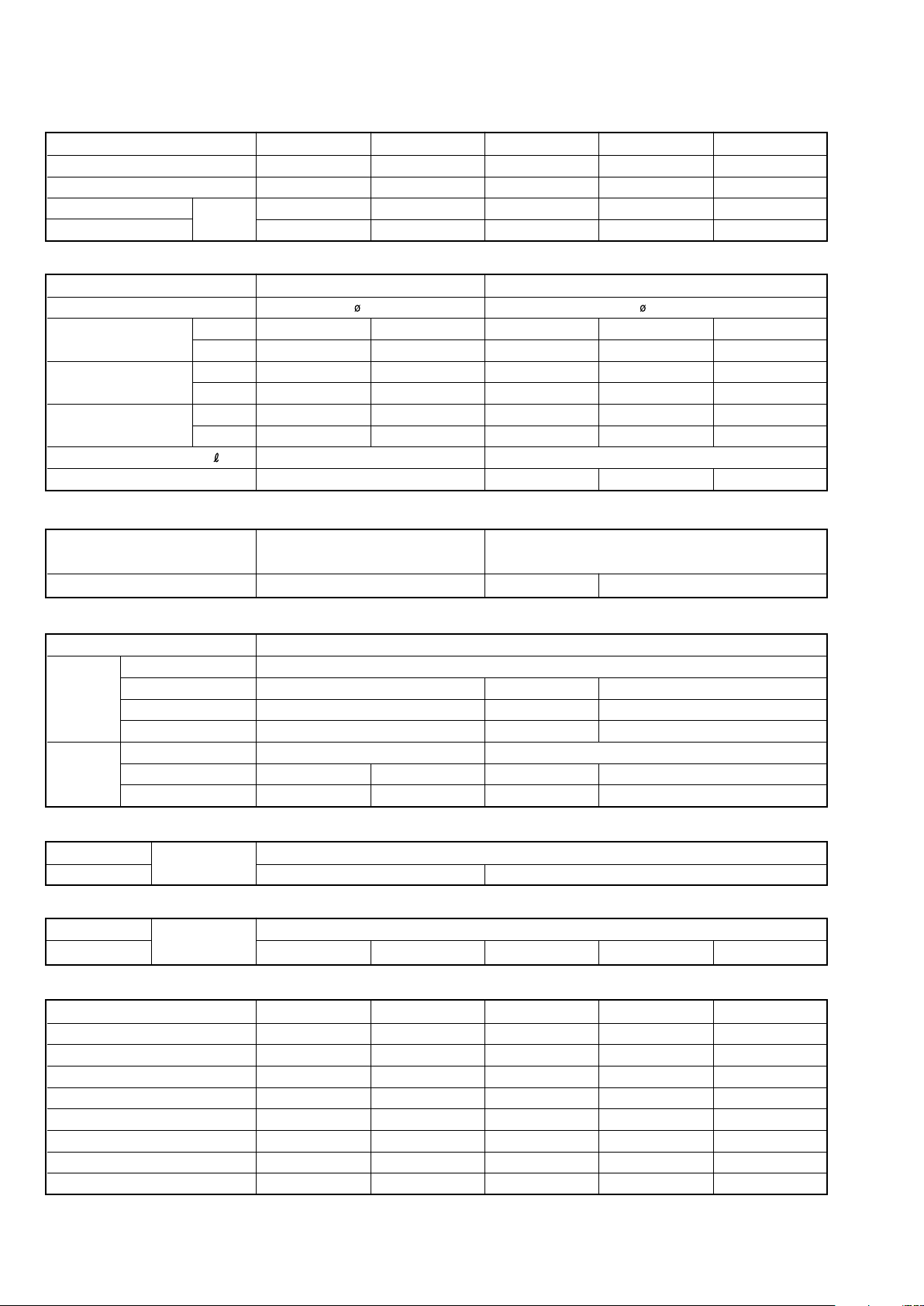
OUTLINE AND DIMENSIONS
INDOOR UNIT
(Unit : mm)
700
1,660 240
2003.05.13
1,600
300
130
– 3 –
Page 5
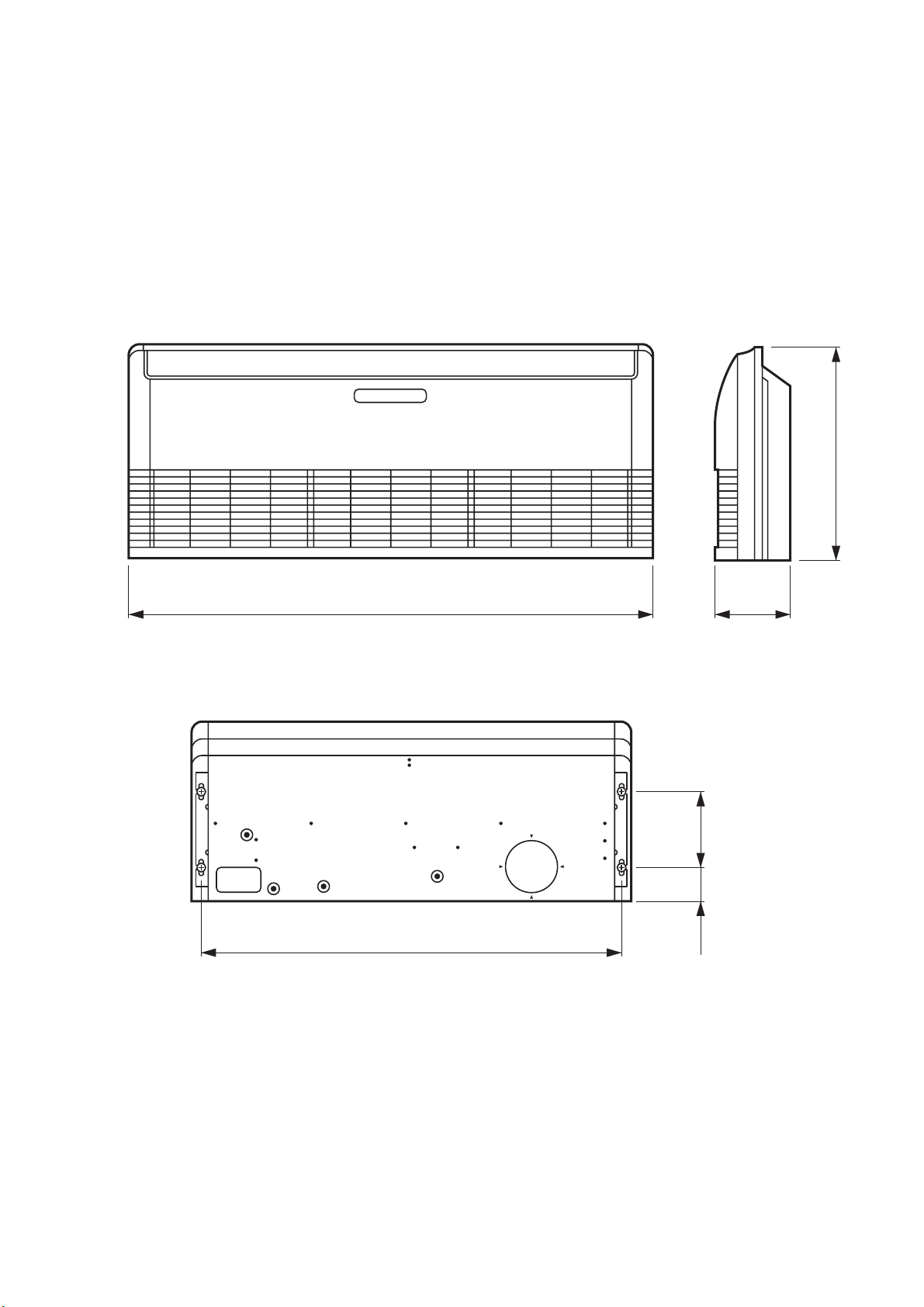
OUTDOOR UNIT
Models : AOG30AMBH, AOG30AMBL, AOG30RMCL
AOY30AMBH, AOY30AMBL, AOY30RMCL
AOT30AMBL, AOT30RMCL
900
930
900
350
(Unit : mm)
804
Models : AOG45RCG3L, AOG54APA3L, AOG54RPA3L
AOY45RCG3L, AOY54APA3L, AOY54RPA3L
AOT45RCG3L, AOT54APA3L, AOT54RPA3L
1,152
23
333
19
370
400
650
940
– 4 –
425
2003.05.13
Page 6
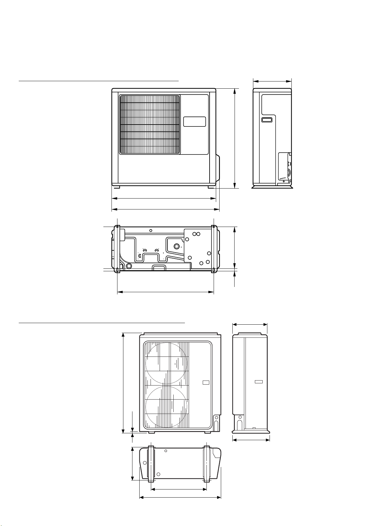
REFRIGERANT SYSTEM DIAGRAM
Evaporator
Distributor
INDOOR UNIT
Refrigerant pipe
15.88mm(5/8")
Refrigerant pipe
9.52mm(3/8")
Capillary tube
Charging valve
Compressor
Dryer
OUTDOOR UNIT
Condenser
Check joint
High pressure
switch
Accumulator
Evaporator
Distributor
INDOOR UNIT
Refrigerant pipe
15.88mm(5/8")
Refrigerant pipe
9.52mm(3/8")
Capillary tube
Charging valve
Compressor
Dryer
OUTDOOR UNIT
Condenser
Check joint
Accumulator
Models : ABG30ABA-W / AOG30AMBH
ABY30ABA-W / AOG30AMBH
Models : ABG30ABA-W / AOG30AMBL
2003.05.13
ABY30ABA-W / AOG30AMBL
ABT30ABA-W / AOT30AMBL
– 5 –
Page 7
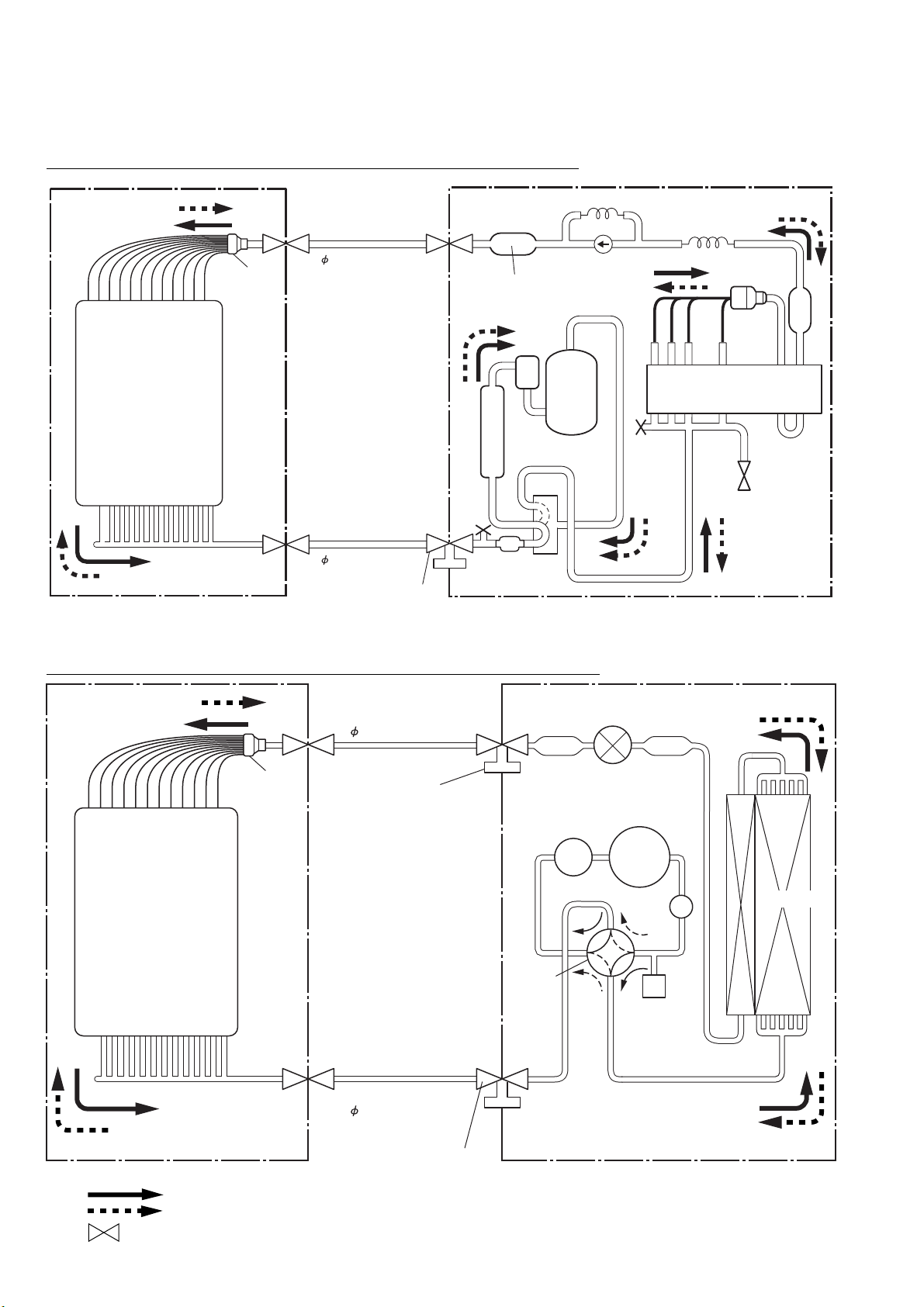
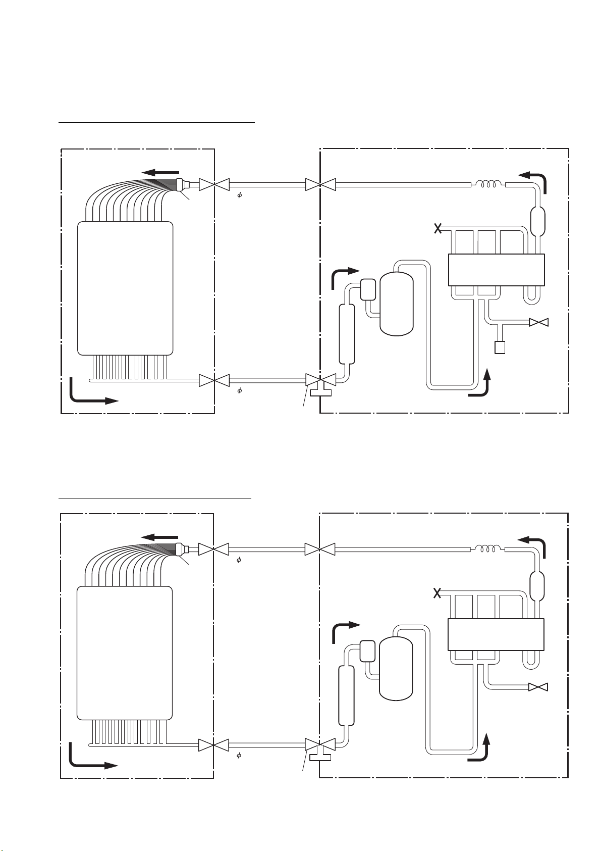
Evaporator
Distributor
INDOOR UNIT
Refrigerant pipe
15.88mm(5/8")
Refrigerant pipe
9.52mm(3/8")
Charging valve
Capillary tube
Strainer
Compressor
Muffler
4-Way
valve
Accumulator
Dryer
OUTDOOR UNIT
Condenser
Distributor
Check joint
DryerStrainer
Expansion Valve
Compressor
Muffler
4-Way
Valve
High
Pressure
Switch
Accumulator
OUTDOOR UNIT
Condenser
Evaporator
Charging valve
Refrigerant pipe
19.05mm (3/4")
Refrigerant pipe
9.52mm (3/8")
Charging valve
Distributor
INDOOR UNIT
Cooling
Heating
: Flare coupling
Models : ABG30RBA-W / AOG30RMCL, ABT30RBA-W / AOT30RMCL
ABY30RBA-W / AOY30RMCL
Models : ABG45RGC3W / AOG45RCG3L, ABG54RBA3W / AOG54RPA3L
ABY45RGC3W / AOY45RCG3L, ABY54RBA3W / AOY54RPA3L
ABT45RGC3W / AOT45RCG3L, ABT54RBA3W / AOT54RPA3L
– 6 –
2003.05.13
Page 8
Models : ABG54ABA3W / AOG54APA3L
Evaporator
Condenser
Dryer
Capillary tube
Thermistor
(Discharge gas)
Accumulator
Charging valve
Refrigerant pipe
19.05mm (3/4")
Compressor
Refrigerant pipe
9.52mm (3/8")
Charging valve
Distributor
INDOOR UNIT OUTDOOR UNIT
Muffler
ABY54ABA3W / AOY54APA3L
ABT54ABA3W / AOT54APA3L
2003.05.13
– 7 –
Page 9
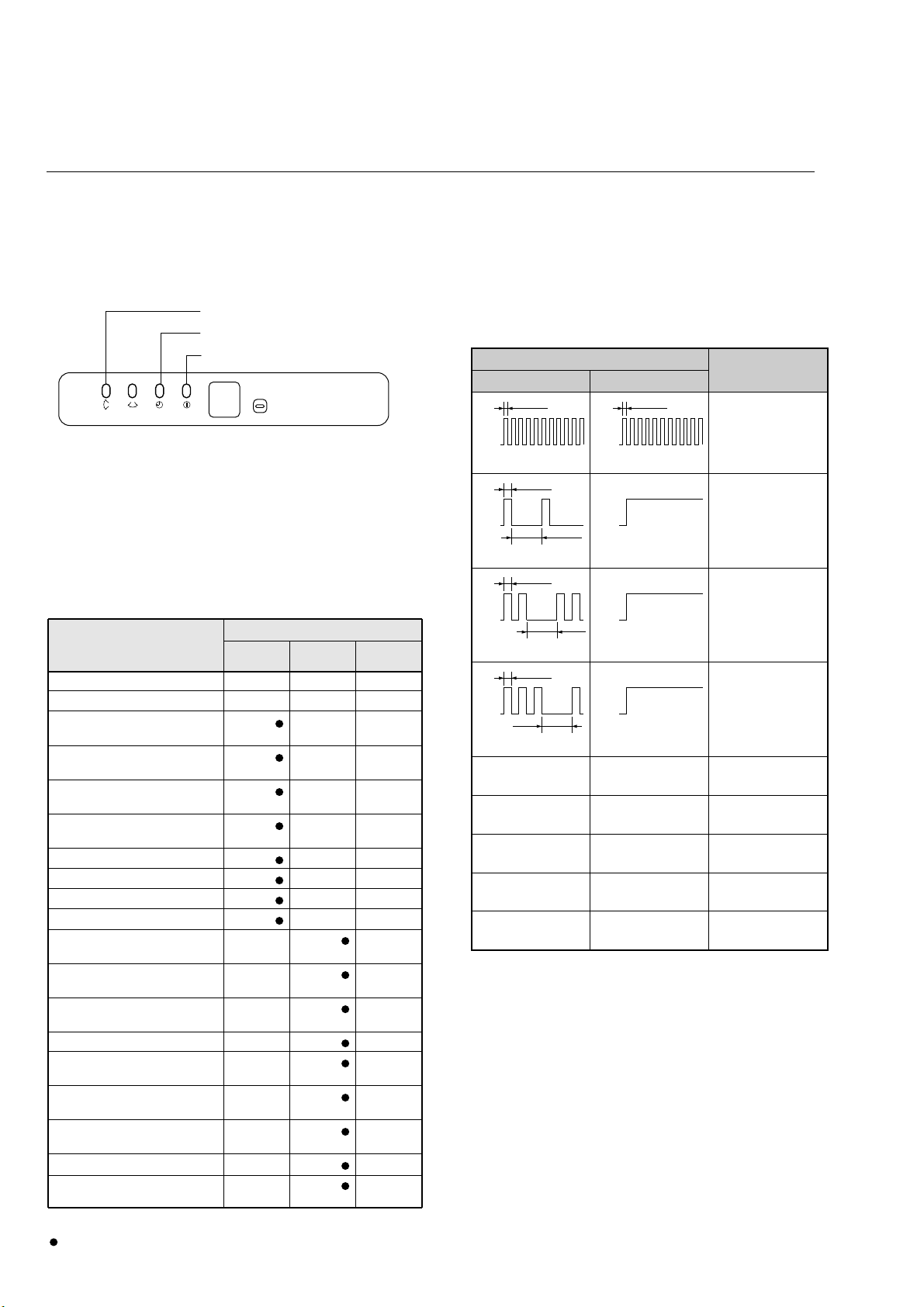
ERROR CONTENTS
Error display
Error contents
LED 1 LED 2
ON
OFF
Quick flash continued
0.1 sec.
ON
OFF
Quick flash continued
0.1 sec.
Model abnormal or
EEPROM abnormal
ON
OFF
1 quick flash repeated
0.5 sec.
2 sec.
ON
OFF
Lighting continued
Power source
connection error
ON
OFF
Lighting continued
Discharge temperature
sensor error
ON
OFF
2 quick flashes repeated
0.5 sec.
2 sec.
ON
OFF
Lighting continued
Outdoor heat
exchanger temperature
sensor error
ON
OFF
3 quick flashes repeated
0.5 sec.
2 sec.
Outdoor temperature
sensor error
4 quick flashes repeated
Lighting continued
Communication signal
error
5 quick flashes repeated
Lighting continued
Indoor unit error
6 quick flashes repeated
Lighting continued
Discharge temperature
abnormal
7 quick flashes repeated
Lighting continued
High pressure
abnormal
8 quick flashes repeated
Lighting continued
SWING SWING TIMER
MANUAL
AUTO
OERATION
VERTICAL SWING lamp (Orange)
TIMER lamp (Green)
OPERATION lamp (Red)
Table 1
Error display
OPERATION TIMER
VERTICAL SWING
lamp lamp lamp
Error contents
Indoor EEPROM abnormal
Outdoor EEPROM abnormal
Indoor room temperature sensor
open
Indoor room temperature sensor
short-circuited
Indoor heat exchanger
temperature sensor open
Indoor heat exchanger
temperature sensor short-circuited
Float switch operated
Indoor signal abnormal
Outdoor signal abnormal
Indoor fan abnormal
Outdoor power source connection
abnormal
Outdoor heat exchanger
temperature sensor open
Outdoor heat exchanger
temperature sensor short-circuited
Outdoor temperature sensor open
Outdoor temperature sensor
short-circuited
Outdoor discharge pipe
temperature sensor open
Outdoor discharge pipe
temperature sensor short-circuited
Outdoor high pressure abnormal
Outdoor discharge pipe
temperature abnormal
OO X
OOO
(2 times)
OX
(2 times)
OO
(3 times)
OX
(3 times)
O
O
(4 times)
OX
(5 times)
OX
(5 times)
O
O
(6 times)
OX
O
(2 times)
X
O
(3 times)
X
O
(3 times)
O
O
(4 times)
X
O
(4 times)
O
O
(5 times)
X
O
(5 times)
O
O
(6 times)
X
O
(7 times)
X
O : 0.1s ON / 0.1s OFF (flash) X : OFF
: 0.5s ON / 0.5s OFF (flash)
Models : ABG30ABA-W / AOG30AMBH, ABY30ABA-W / AOG30AMBH, ABG30RBA-W / AOG30RMCL
ABT30RBA-W / AOT30RMCL, ABY30RBA-W / AOY30RMCL, ABG30ABA-W / AOG30AMBL,
ABY30ABA-W / AOG30AMBL, ABT30ABA-W / AOT30AMBL
1. INDOOR UNIT
Operation can be checked by lighting and flashing of the
display section OPERATION, TIMER, and VERTICAL SWING
lamps.
Perform judgment in accordance with the following.
TEST RUNNING
When the air conditioner is run by pressing the remote control
unit test run button, the OPERATION, TIMER, and VERTICAL
SWING lamps flash slowly at the same time.
ERROR
The OPERATION, TIMER, and VERTICAL SWING lamps
operate as follows (Table 1) according to the error contents.
2. OUTDOOR UNIT
ERROR : Heat & Cool model (Reverse cycle) only
The LED lamps operate as follows (Table 2) according to the
error contents.
Table 2
When the fault is cleared, the LED lamp goes off.
However, for discharge pipe temperature abnormal and high
pressure abnormal, the LED lamp lights continuously for 24
hours, as long as the power is not turned off.
– 8 –
2003.05.13
Page 10
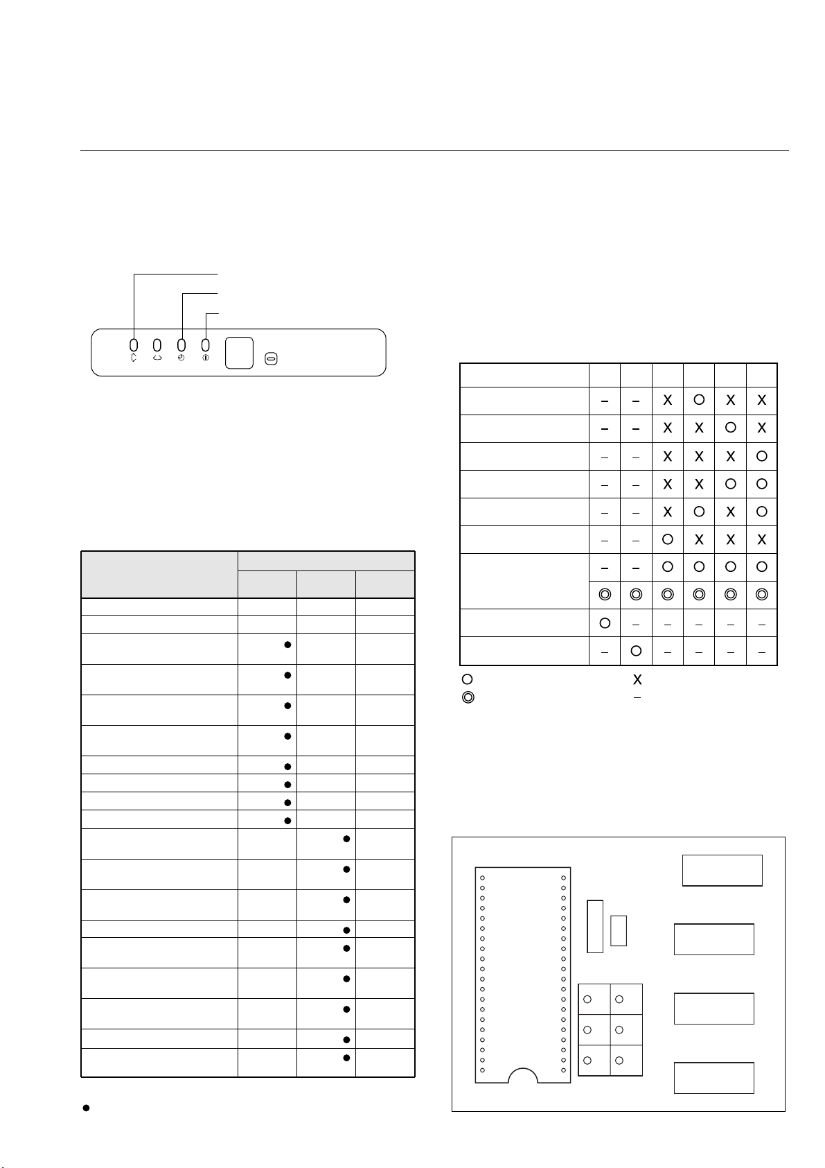
Models : ABG45RGC3W / AOG45RCG3L, ABY45RGC3W / AOY45RCG3L, ABT45RGC3W / AOT45RCG3L
Error contents LED1 LED2 LED3 LED4 LED5 LED6
Signal abnormal
Indoor unit abnormal
Discharge pipe
temperature abnormal
Outdoor heat exchanger
temperature abnormal
Outdoor temperature
abnormal
Power source
connection error
EEPROM abnormal
Outdoor high pressure
abnormal
Discharge pipe
temperature abnormal
: 0.5s ON / 0.5s OFF (flash) : OFF
: 0.1s ON / 0.1s OFF (flash) : Indefinite
IC1
CN14
TEST
LED1
LED2 LED3
LED4 LED5 LED6
SWING SWING TIMER
MANUAL
AUTO
OERATION
VERTICAL SWING lamp (Orange)
TIMER lamp (Green)
OPERATION lamp (Red)
Table 1
Error display
OPERATION TIMER
VERTICAL SWING
lamp lamp lamp
Error contents
Indoor EEPROM abnormal
Outdoor EEPROM abnormal
Indoor room temperature sensor
open
Indoor room temperature sensor
short-circuited
Indoor heat exchanger
temperature sensor open
Indoor heat exchanger
temperature sensor short-circuited
Float switch operated
Indoor signal abnormal
Outdoor signal abnormal
Indoor fan abnormal
Outdoor power source connection
abnormal
Outdoor heat exchanger
temperature sensor open
Outdoor heat exchanger
temperature sensor short-circuited
Outdoor temperature sensor open
Outdoor temperature sensor
short-circuited
Outdoor discharge pipe
temperature sensor open
Outdoor discharge pipe
temperature sensor short-circuited
Outdoor high pressure abnormal
Outdoor discharge pipe
temperature abnormal
OO X
OOO
(2 times)
OX
(2 times)
OO
(3 times)
OX
(3 times)
O
O
(4 times)
OX
(5 times)
OX
(5 times)
O
O
(6 times)
OX
O
(2 times)
X
O
(3 times)
X
O
(3 times)
O
O
(4 times)
X
O
(4 times)
O
O
(5 times)
X
O
(5 times)
O
O
(6 times)
X
O
(7 times)
X
O : 0.1s ON / 0.1s OFF (flash) X : OFF
: 0.5s ON / 0.5s OFF (flash)
ABG54ABA3W / AOG54APA3L, ABY54ABA3W / AOY54APA3L, ABT54ABA3W / AOT54APA3L,
ABG54RBA3W / AOG54RPA3L, ABY54RBA3W / AOY54RPA3L, ABT54RBA3W / AOT54RPA3L
1. INDOOR UNIT
Operation can be checked by lighting and flashing of the
display section OPERATION, TIMER, and VERTICAL SWING
lamps.
Perform judgment in accordance with the following.
TEST RUNNING
When the air conditioner is run by pressing the remote control
unit test run button, the OPERATION, TIMER, and VERTICAL
SWING lamps flash slowly at the same time.
ERROR
The OPERATION, TIMER, and VERTICAL SWING lamps
operate as follows (Table 1) according to the error contents.
2. OUTDOOR UNIT
When the outdoor temperature drops, the outdoor unit's fans
may switch to low speed, or one of the fans may stop
intermittently.
ERROR : Reverse cycle only
The LED lamps operate as follows (Table 2) according to the
error contents.
Table 2
2003.05.13
When the fault is cleared, the LED lamp goes off.
However, for discharge pipe temperature abnormal and high
pressure abnormal, the LED lamp lights continuously for 24
hours, as long as the power is not turned off.
ERROR LED DISPLAY LAYOUT
– 9 –
Page 11
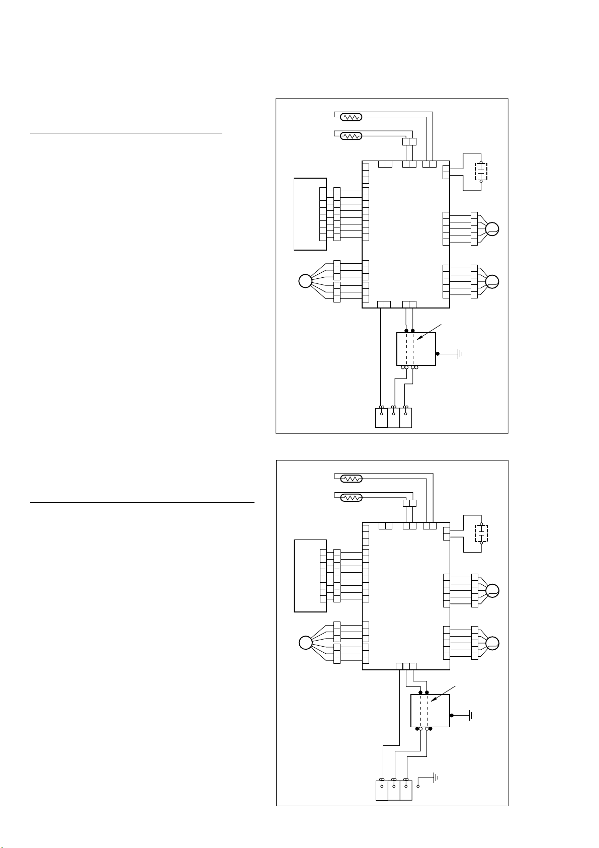
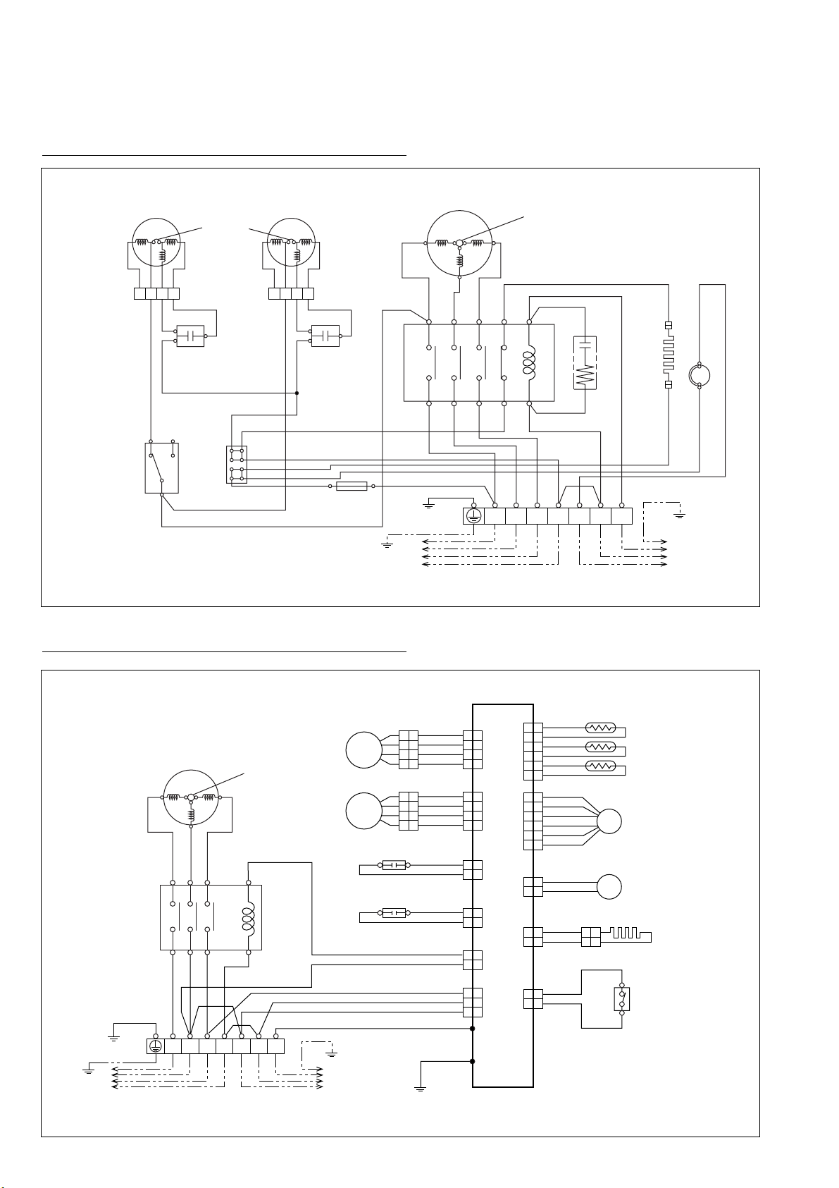
CIRCUIT DIAGRAM
THERMISTOR (PIPE TEMP.)
FAN MOTOR
CAPACITOR
STEP MOTOR
(UP/DOWN)
GRAY
GRAY
GRAY
GRAY
1 2
1 2
THERMISTOR (ROOM TEMP.)
BLACK
CN 7
1 2
CN 6
RED
2 13
WHITE
WHITE
GREEN
1
NL
CN 1
1 2
1
2
CN 8
CN 4
1
2
3
4
5
1
2
3
4
5
CN 10
BLACK
WHITE
WHITE
BROWN
RED
ORANGE
YELLOW
WHITE
M
STEP MOTOR
(LEFT/RIGHT)
1
2
3
4
5
1
2
3
4
5
CN 11
BROWN
RED
ORANGE
YELLOW
WHITE
M
FAN MOTOR
Use T3.15A-250V
Fuse on F101
TERMINAL
FILTER
BOARD
DISPLAY BOARD
CONTROL BOARD
1
2
3
1
2
3
4
5
6
7
8
1
2
3
4
5
6
7
8
CN 16
1
2
3
CN 15CN 13
CN 201
1
3
5
1
2
3
2
1
3
CN 5
GRAY
PURPLE
BLUE
BROWN
RED
ORANGE
YELLOW
WHITE
BLUE
PURPLE
GRAY
1
2
3
4
5
6
7
8
BLACK
WHITE
RED
FM
2
(N)
3
BLACK
BLACK
THERMISTOR (PIPE TEMP.)
FAN MOTOR
CAPACITOR
STEP MOTOR
(UP/DOWN)
GRAY
GRAY
GRAY
GRAY
GRAY
1 2
1 2
THERMISTOR (ROOM TEMP.)
BLACK
CN 7
1 2
1 21 2
CN 6
WHITE
WHITE
GREEN
1
NL
CN 1CN 19
1 2
1
2
CN 8
CN 4
1
2
3
4
5
1
2
3
4
5
CN 10
BLACK
WHITE
WHITE
BROWN
RED
ORANGE
YELLOW
WHITE
M
STEP MOTOR
(LEFT/RIGHT)
1
2
3
4
5
1
2
3
4
5
CN 11
BROWN
RED
ORANGE
YELLOW
WHITE
M
FAN MOTOR
Use T3.15A-250V
Fuse on F101
TERMINAL
FILTER
BOARD
DISPLAY BOARD
CONTROL BOARD
1
2
3
1
2
3
4
5
6
7
8
1
2
3
4
5
6
7
8
CN 16
1
2
3
CN 15CN 13
CN 201
1
2
3
1
2
3
2
1
3
CN 5
GRAY
PURPLE
BLUE
BROWN
RED
ORANGE
YELLOW
WHITE
BLUE
PURPLE
GRAY
1
2
3
4
5
6
7
8
BLACK
WHITE
RED
FM
2
(N)
3
BLACK
BLACK
Models : ABG30ABA-W, ABG54ABA3W
ABY30ABA-W, ABY54ABA3W
ABT30ABA-W, ABT54ABA3W
Models :
ABG30RBA-W, ABG45RGC3W, ABG54RBA3W
ABY30RBA-W, ABY45RGC3W, ABY54RBA3W
ABT30RBA-W, ABT45RGC3W, ABT54RBA3W
– 10 –
2003.05.13
Page 12
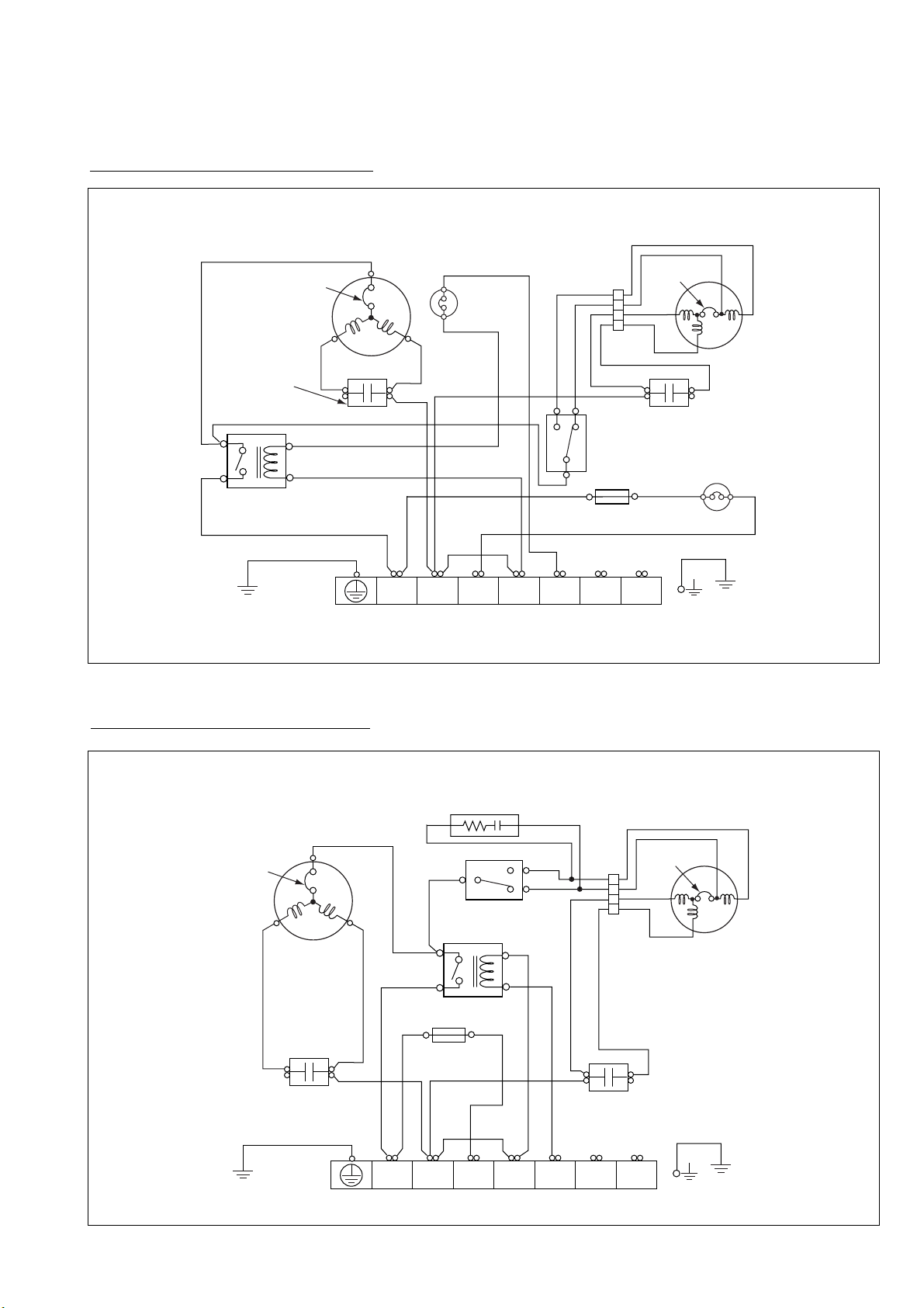
Models : AOG30AMBH, AOY30AMBH
(N)
LN 1
32
C
RS
BLACK
BLUE
RED
BLACK
RED
GREEN/YELLOW
BLACK
BLACK
BLACK
BLACK
BLACK
BROWN
BROWN
BROWN
WHITE
WHITE
WHITE
WHITE
WHITE
6
5
4
1
H
L
C
FAN
MOTOR
FUSE
5A
TERMINAL
FAN MOTOR
CAPACITOR
COMPRESSOR
CAPACITOR
COMPRESSOR
MAIN RELAY
THERMAL
PROTECTOR
INTERNAL
OVERLOAD
PROTECTOR
CONNECTOR
OUTDOOR
THERMOSTAT
PRESSURE
SWITCH
THERMAL
SWITCH
(N)
LN 1
32
C
RS
BLACK
BLACK
BLUE
RED
BLACK
BLACK
BLACK
RED
GREEN/YELLOW
BLACK
WHITE
WHITE
WHITE
WHITE
WHITE
FAN
MOTOR
TERMINAL
FAN MOTOR
CAPACITOR
COMPRESSOR
CAPACITOR
COMPRESSOR
THERMAL
PROTECTOR
INTERNAL
OVERLOAD
PROTECTOR
CONNECTOR
CR COMPOSITE
H
L
C
OUTDOOR
THERMOSTAT
BROWN
BROWN
6
5
4
1
MAIN RELAY
FUSE
5A
2003.05.13
Models : AOG30AMBL, AOY30AMBL
– 11 –
Page 13
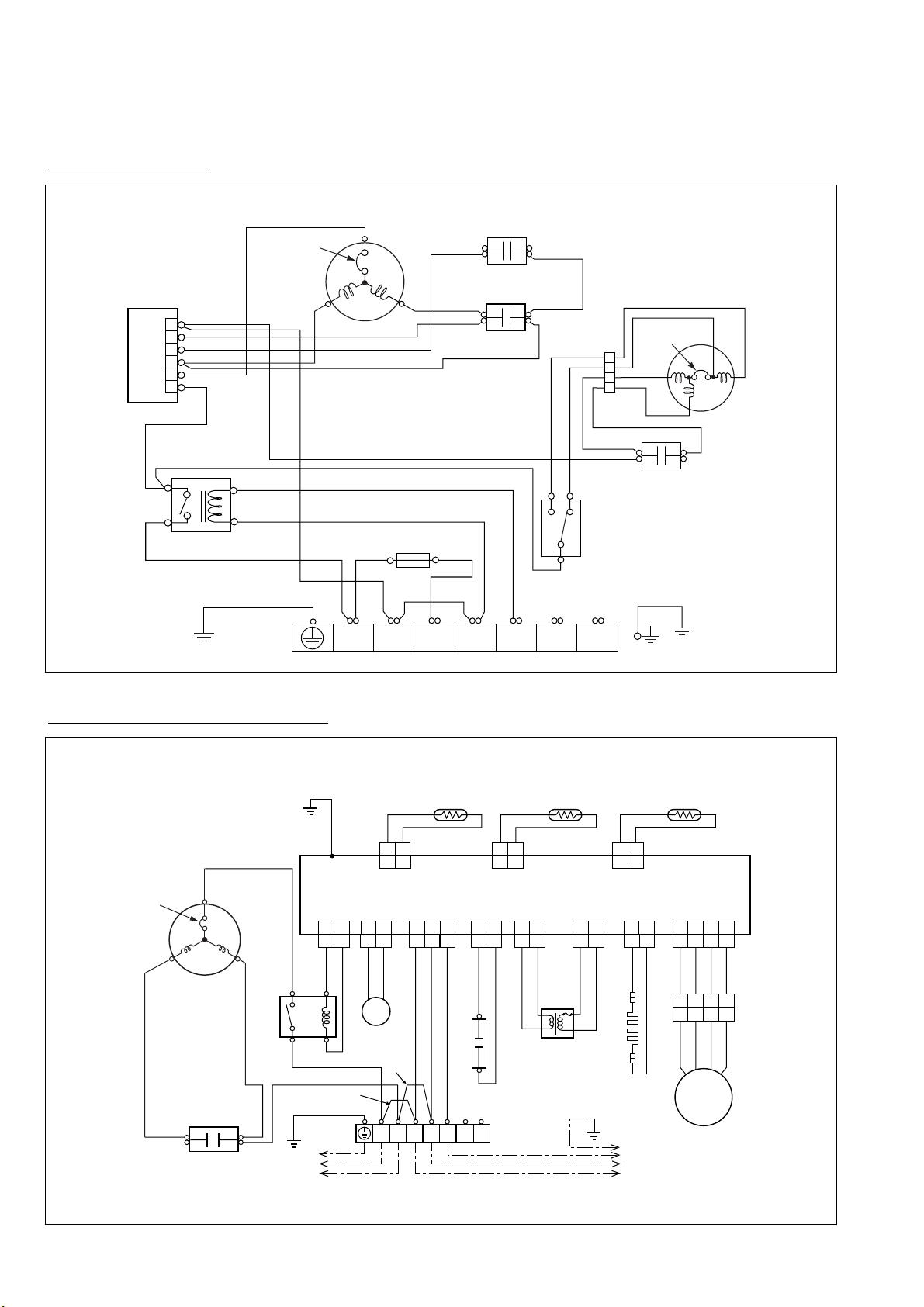
TRANSFORMER
SOLENOID
COIL
FAN MOTOR
CAPACITOR
COMPRESSOR
CAPACITOR
COMPRESSOR
C
S
R
MAIN RELAY
TERMINAL
THERMISTOR
(PIPE TEMP.)
THERMISTOR
(OUTDOOR TEMP.) (DISCHARGE TEMP.)
THERMISTOR
GREEN
GREEN/YELLOW
PURPLE
PURPLE
WHITE
WHITE
BLACK
BLACK
BLACK
BLUE
BLACK
BLACK
BLACK
BLACK
GRAY
GRAY
BROWN
BROWN
RED
RED
RED
RED
WHITE
WHITE
WHITE
BLACK
BLACK
BLACK
BLUE
RED
WHITE
BLACK
BLUE
RED
RED
RED
WHITE
WHITE
CN15 CN9 CN1 CN4 CN3 CN2 CN5
CN11
E
CN12 CN13
FUSE
T 3.15A 250V
CONTROL BOARD
12 12 12
12
CN8
12
4321
121212
1212
3
FAN
MOTOR
4WV
L N 3
2
(N)
1
TO INDOOR UNIT
TO POWER SUPPLY
15
46
INTERNAL
OVERLOAD
PROTECTOR
BELT
HEATER
Model : AOT30AMBL
(N)
LN 1
32
BLUE
BLUE
RED
RED
RED
RED
GREEN/YELLOW
BLACK
BLACK
BLACK
BLACK BLACK BLACK
GRAY
BROWN
BROWN
WHITE
WHITE
WHITE
TERMINAL
SOFT STARTER
6
4
3
2
1
5
FUSE
5A
H
L
C
OUTDOOR
THERMOSTAT
6
5
4
1
MAIN RELAY
C
RS
COMPRESSOR
INTERNAL
OVERLOAD
PROTECTOR
BLACK
WHITE
FAN
MOTOR
FAN MOTOR
CAPACITOR
THERMAL
PROTECTOR
CONNECTOR
WHITE
COMPRESSOR
CAPACITOR (RUN)
COMPRESSOR
CAPACITOR (START)
Models : AOG30RMCL, AOY30RMCL
– 12 –
2003.05.13
Page 14
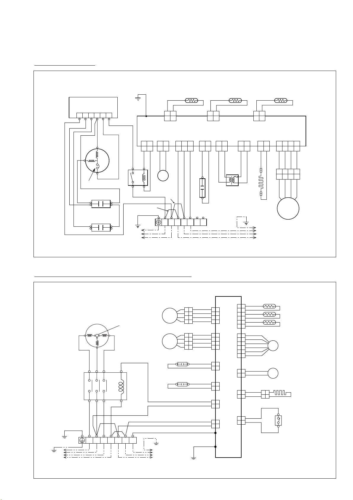
TO POWER SUPPLY TO INDOOR UNIT
BLACK
WHITE
RED
T1 T3
T2
246 A1/A
INTERNAL
OVERLOAD
PROTECTOR
135 A2/B
TERMINAL
COMPRESSOR
MAGNETIC RELAY
BELT HEATER
HIGH
PRESSURE SWITCH
GREEN/YELLOW
THERMISTOR
EXPANSION
VALVE COIL
SOLENOID COIL
BROWN
BROWN
BLACK
BLACK
BLACK
BLACK
BLACK
BLACK
(DISCHARGE TEMP.)
(OUTDOOR TEMP.)
(PIPE TEMP.)
CN 9
WHITE
YELLOW
ORANGE
BLUE
BROWN
RED
CN 11CN 4
FAN MOTOR (UPPER)
BLUE
RED
WHITE
BLACK
CN 16
FAN MOTOR (LOWER)
FAN MOTOR
CAPACITOR (UPPER)
BLUE
RED
WHITE
BLACK
CN 3
YELLOW
YELLOW
CN 15
BLACK
BLACK
CN 6
BLUE
BLUE
CN 13
FAN MOTOR
CAPACITOR (LOWER)
YELLOW
BLACK
YELLOW
CN 2
WHITE
FUSE
T 6.3A 250V
WHITE
GRAY
RED
WHITE
BLACK
BLACK
RED
WHITE
BLUE
GREEN
CN 22
W1E
CN 7
CONTROL BOARD
13NTSR
2
(N)
1 2 3 4 5 61 21 21 2 1 2 3 4 5 6
EV
1 2 3 4
FM
1 2 3 41 21 21 21 2
FM
4WV
Model : AOT30RMCL
TRANSFORMER
SOLENOID
COIL
FAN MOTOR
CAPACITOR
COMPRESSOR
CAPACITOR
COMPRESSOR
C
S
R
MAIN RELAY
TERMINAL
THERMISTOR
(PIPE TEMP.)
THERMISTOR
(OUTDOOR TEMP.) (DISCHARGE TEMP.)
THERMISTOR
GREEN
GREEN/YELLOW
PURPLE
PURPLE
WHITE
BLACK
BLACK
BLACK
BLACK
BLUE
BLUE
BLACK
BLACK
BLACK
BLACK
GRAY
GRAY
GRAY
BROWN
BROWN
RED
RED
RED
RED
RED
RED
WHITE
WHITE
WHITE
BLACK
BLACK
BLACK
BLUE
RED
WHITE
BLACK
BLUE
RED
RED
RED
WHITE
WHITE
WHITE
CN15 CN9 CN1 CN4 CN3 CN2 CN5
CN11
E
CN12 CN13
FUSE
T 3.15A 250V
CONTROL BOARD
SOFT STARTER
12 12 12
12
CN8
12
4321
121212
1212
3
FAN
MOTOR
4WV
L N 3
2
(N)
1
TO INDOOR UNIT
TO POWER SUPPLY
START
CAPACITOR
15
46
OVERLOAD
PROTECTOR
4365 21
BELT
HEATER
Models : AOG45RCG3L, AOY45RCG3L, AOT45RCG3L
2003.05.13
– 13 –
Page 15
TO POWER SUPPLY TO INDOOR UNIT
BLACK
WHITE
RED
T1 T3
T2
246 A1/A
INTERNAL
OVERLOAD
PROTECTOR
135 A2/B
TERMINAL
COMPRESSOR
MAGNETIC RELAY
BELT HEATER
HIGH
PRESSURE SWITCH
GREEN/YELLOW
THERMISTOR
EXPANSION
VALVE COIL
SOLENOID COIL
BROWN
BROWN
BLACK
BLACK
BLACK
BLACK
BLACK
BLACK
(DISCHARGE TEMP.)
(OUTDOOR TEMP.)
(PIPE TEMP.)
CN 9
WHITE
YELLOW
ORANGE
BLUE
BROWN
RED
CN 11CN 4
FAN MOTOR (UPPER)
BLUE
RED
WHITE
BLACK
CN 16
FAN MOTOR (LOWER)
FAN MOTOR
CAPACITOR (UPPER)
BLUE
RED
WHITE
BLACK
CN 3
YELLOW
YELLOW
CN 15
BLACK
BLACK
CN 6
BLUE
BLUE
CN 13
FAN MOTOR
CAPACITOR (LOWER)
YELLOW
BLACK
YELLOW
CN 2
WHITE
FUSE
T 6.3A 250V
WHITE
GRAY
RED
WHITE
BLACK
BLACK
RED
WHITE
BLUE
GREEN
CN 22
W1E
PINK
CN 7
CONTROL BOARD
13NTSR
2
(N)
1 2 3 4 5 61 21 21 2 1 2 3 4 5 6
EV
1 2 3 4
FM
1 2 3 41 21 21 21 2 3
FM
4WV
Models : AOG54APA3L, AOY54APA3L, AOT54APA3L
LCN
TO POWER SUPPLY TO INDOOR UNIT
BLACK
BLACK
WHITE
RED
RED
T1 T3
T2
24632 A1/A
INTERNAL
OVERLOAD
PROTECTOR
THERMAL
PROTECTOR
13531 A2/B
WHITEWHITE
FAN MOTOR
(LOWER)
FAN
CAPACITOR
TERMINAL
FUSE
5A
COMPRESSOR
MAGNETIC RELAY
CR COMPOSITE
CRANKCASE HEATER
THERMOSTAT
(DISCHARGE PIPE)
CONNECTOR
BLACK
WHITE
RED
WHITE
RED
BLACK
BLACK
BLACK
GRAY
BLUE
BLUE
GREEN/YELLOW
BLUE
BLUE
BLUE
FAN MOTOR
(UPPER)
FAN
CAPACITOR
OUTDOOR
THERMOSTAT
TERMINAL
CONNECTOR
WHITE
BROWN
WHITE
WHITE
BLACK
BLACK
13NTSR
2
(N)
Models : AOG54RPA3L, AOY54RPA3L, AOT54RPA3L
– 14 –
2003.05.13
Page 16
REMOTE CONTROL CUSTOM CODE
SWITCHING (R1)
REMOTE CONTROL CUSTOM CODE
SWITCHING (R2)
INDICATOR PCB
EZ-097JHSE-D
AUTO R ESTARTE SWITCHING
ROOM TEMPERATURE CORRECTION
( HEATING OPERATION )
ROOM TEMPERATURE CORRECTION
( HEATING OPERATION )
OUTDOOR UNIT
POWER SOURCE
220 - 240V
50Hz
5V
CONTROLLER PCB ASSEMBLY ( MAIN PCB )
ABG30ABA-W,ABY30ABA-W,ABT30ABA-W : EZ-0020GWSE-C
ABG54ABA3W,ABY54ABA3W,ABT54ABA3W : EZ-0020FWSE-C
Models : ABG30ABA-W, ABG54ABA3W
ABY30ABA-W, ABY54ABA3W
ABT30ABA-W, ABT54ABA3W
INDOOR PRINTED CIRCUIT BOARD
CIRCUIT DIAGRAM
2003.05.13
– 15 –
Page 17
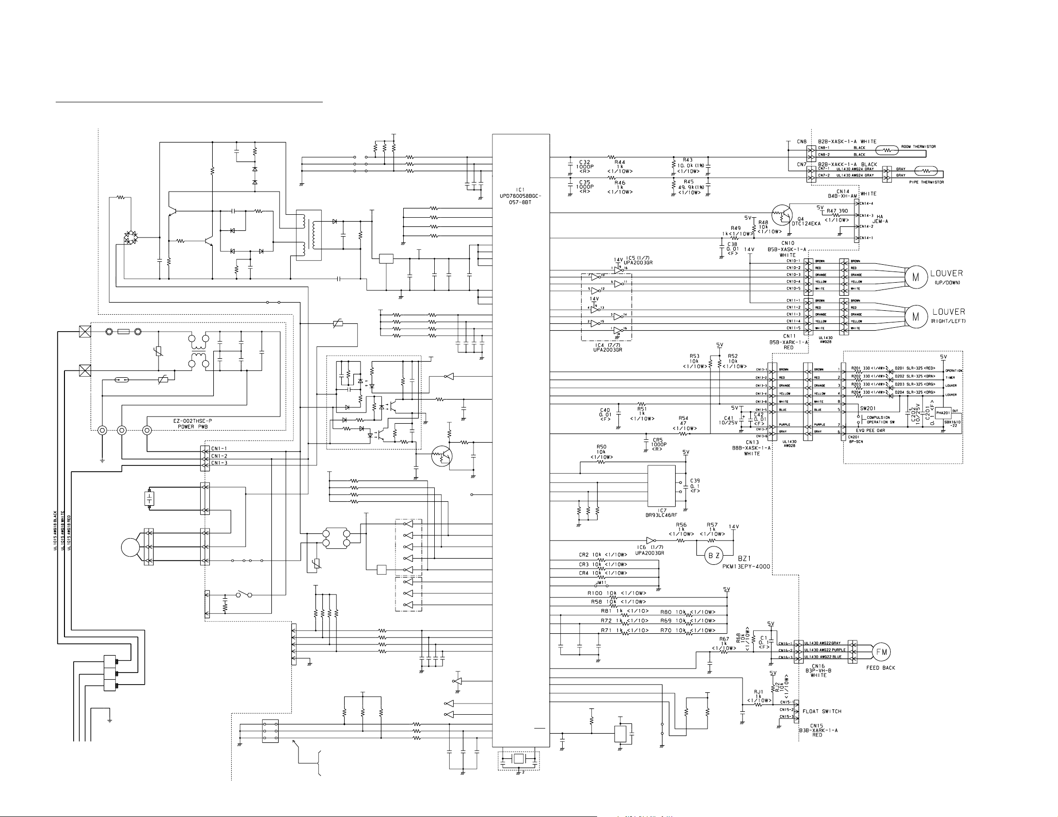
5V
R18 1.0K <1/10W>
R20 1.0K <1/10W>
R19 1.0K <1/10W>
C19 - C21
0.01 x 3
<F>
14V
R15 - R17
10K <1/10W> x 3
REMOTE CUSTOM CODE
SWITCHING (R1)
REMOTE CUSTOM CODE
SWITCHING (R2)
JM1
JM2
JM3
R59 10K <1/10W>
R98 10K <1/10W>
R97 10K <1/10W>
R99 10K <1/10W>
5V
IC3
7805
IO
G
C13
0.1
<F>
C14
100/
6.3V
+
C15
0.1
<F>
C47
0.1
<F>
5V
R33 - R36
1.0K <1/4W> x 4
R29 - R32
10K <1/10W> x 4
VA1
470V
C54
0.01
<F>
C26 - C29
0.01 <F> x 4
5V
IC5 (1/7)
uPA2003GR
CR1
0.01
<F>
R14 10K
<1/10W>
5V
CR6
0.01
<F>
R10 10K
<1/10W>
R9 390
<1/10W>
Q3
DTC124EKA
C17
0.01
<F>
NC
IC10 HI2002
5V
R93 - R96
10K <1/10W> x 4
14V
IC5 (5/7)
uPA2003GR
K 4
SSR1
G3MC-202PL-VD
DC12V
+
-
VA2
470V
5V
IC6 (3/7)
uPA2003GR
R21 - R24
10K <1/10W> x 4
R25 - R28
1.0K <1/10W> x 4
5V
C22 - C25
0.01 x 4
<F>
14V
IC6 (1/7)
uPA2003GR
IC6 (2/7)
uPA2003GR
R42 1.0K <1/10W>
R41 1.0K <1/10W>
R40 1.0K <1/10W>
C10
0.01
<F>
C30
0.01
<F>
C12
0.01
<F>
X1 CSTS0500MG03-T
SW1
DSS803
NO.1
NO.2
NO.3
R38 10K
<1/10W>
R39 10K
<1/10W>
R37 10K
<1/10W>
TEST
CN9
B5P-SHF-1AA
WHITE
JM8
JM5
CN5
B3P5-VH-B
WHITE
G5NB-1A
K4
C3 0.22 <275V>
R88 120 <1/2W>
CN6
B2P3-VH-B-E
BLUE
DRAIN PUMP
FAN MOTOR
OUTDOOR UNIT
TERMINAL BOARD
2(N)
1
3
F M
FAN CAPACITOR
CN4
B2P3-VH-B-Y
YELLOW
CN1 B3P5-VH-B-C
AC IN
BLACK
W104W103
E101
TM102
SA101
3600V
VA101
470V
VA102
470V
TM101
LF101
F101
3.15A
<250V>
BET
FH102
FH101
N
L
ELF20N018A
C103
0.01
<F>
C106
0.01
<F>
C105
0.01
<F>
C104
0.01
<F>
C101
0.22
275V
JM6
+
C8
100/
6.3V
R7
330
<1/4W>
D4
D1FL20U
D2
D1FL20U
D3
MTZJ5.1B
R6 100
<1/2W>
C7 0.047
50V
D6
D2FL20U
T1
SWITCHING TRANSFORMER
ZFT29B01
PRIMARY
SECONDARY
C9
1000
/25V
+
R8 10K
<1/10W>
R5
62K
<2W>
C6
4700P
600V
R4
330K
<2W>
D5
1SR139-600
D10
1SR139-600
Q1
2SC4236
+
D1
D3SB60
R2
1.5
<2W>
C5
100/
450V
R1 3.3
<5W>
Q2
2SC1815
R3 100
<1/10W>
CN4-1
CN4-2
UL1015 AWG20
WHITE
UL1015 AWG20 WHITE
UL1015 AWG18 WHITE
UL1015 AWG18 BLACK
UL1015 AWG16
GREEN
UL1015 AWG20 WHITE
UL1015 AWG20 BLACK
UL1015 AWG20 RED
CN5-1
CN5-3
CN5-2
CN6-2
CN6-1
CN9-1
CN9-5
CN9-4
CN9-3
CN9-2
AUTO RESTART SWITCHING
ROOM TEMPERATURE CORRECTION
( HEATING OPERATION )
ROOM TEMPERATURE CORRECTION
( HEATING OPERATION )
1
710
16
8
9
215
5
4
3
12
13
14
15
14
13
12
11 6
5
4
3
2
4
3
2
5
1
10
7
18
14
10
1
2
3
54
55
66
65
74
68
75
7
4
67
33
56
57
58
59
41
42
63
72
40
39
38
37
36
52
51
49
43
44
45
46
48
53
47
19
20
21
1
3
70 69
X1 X2
60
14
15
71
73
64
22
23
24
25
26
61
78
79
80
50
6
10
9
8
62
32
31
30
29
28
5
11
12
13
16
17
18
27
34
35
77
76
P15
P16
P17
P122
P123
P05
P04
VDD0
VDD1
AVRF 0
AVRF1
AVSS
VSS0
VSS1
P124
P125
P126
P127
P65
P66
P02
XT2
P64
P63
P62
P61
P60
P120
P37
P35
P67
P30
P31
P32
P34
P121
P33
P40
P41
P42
RESET
P23
P24
I C
XT1
P03
P43
P44
P45
P46
P47
P00
P12
P13
P14
P36
P131
P72
P71
P70
P01
P55
P54
P53
P52
P51
P130
P20
P21
P22
P25
P26
P27
P50
P56
P57
P11
P10
C44
0.1
<F>
5V
5V
R55 10K
<1/10W>
C45
0.1
<F>
JM10
5V
IC8
PST
600C
3
1
2
4
3
2
1
8
7
6
5
D0
D1
SK
CS
GND
NC
NC
VCC
611
R77 - R79
10K <1/10W> x 3
R76 10K
<1/10W>
R75 10K
<1/10W>
C49
0.01
<F>
CR7
0.01
<F>
C31
0.01
<F>
C43
0.01
<F>
C16
0.01
<F>
INDICATOR PCB
EZ-097JHSE-D
POWER SOURCE
220 - 240V
50Hz
CONTROLLER PCB ASSEMBLY (MAIN PCB)
ABG30RBA-W,ABY30RBA-W,ABT30RBA-W : EZ-0027HSE-C
ABG45RGC3W,ABY45RGC3W,ABT45RGC3W : EZ-0022AHSE-C
ABG54RBA3W,ABY54RBA3W,ABT54RBA3W : EZ-002THSE-C
5V
C34
0.1
<F>
C37
0.1
<F>
Models : ABG30RBA-W, ABG45RGC3W, ABG54RBA3W
ABY30RBA-W, ABY45RGC3W, ABY54RBA3W
ABT30RBA-W, ABT45RGC3W, ABT54RBA3W
– 16 –
2003.05.13
Page 18
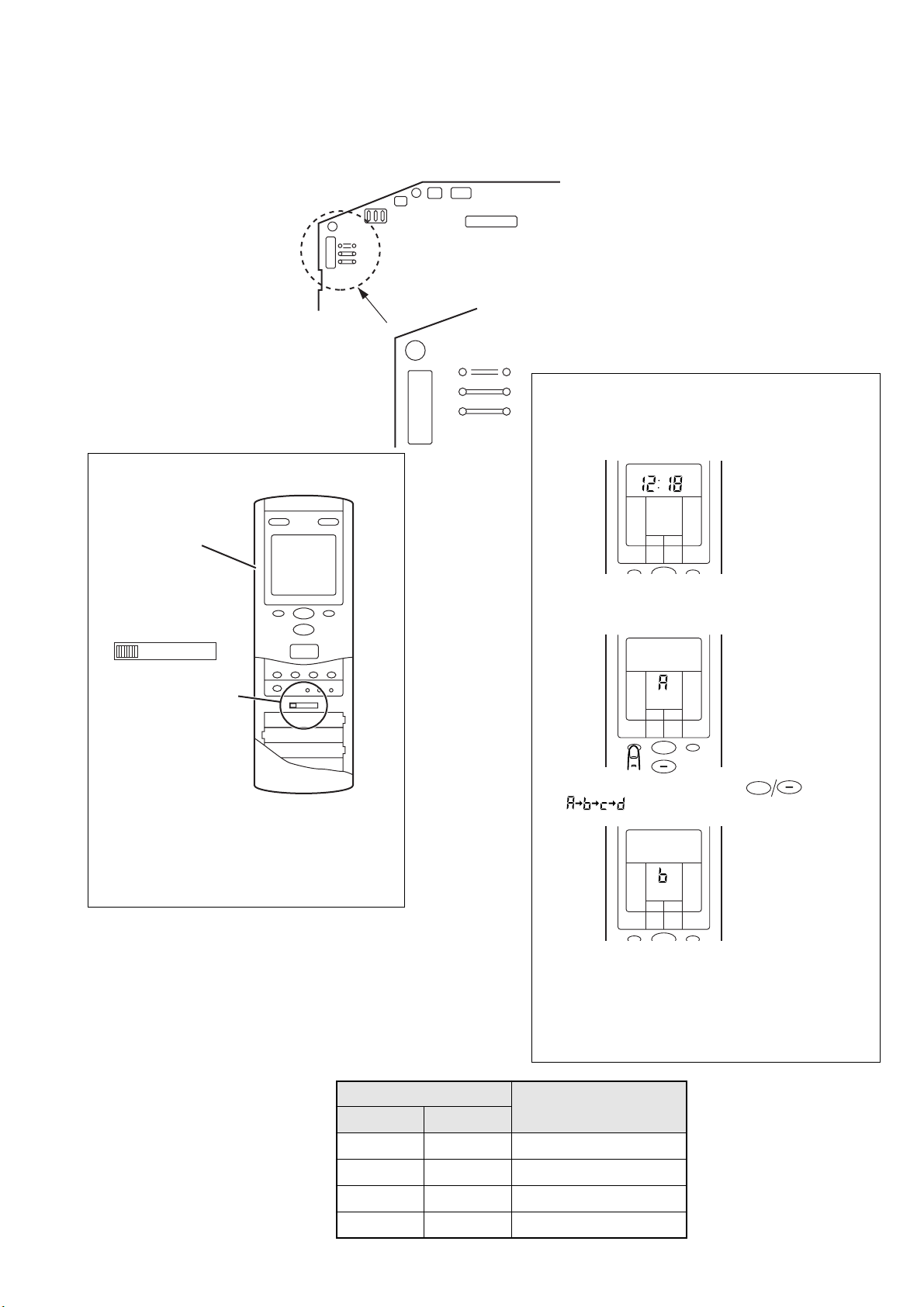
REMOTE CONTROL UNIT CODE SWITCHING
JM1
JM2
JM3
JM1
JM2
JM3
ABCD
A
Remote control unit
signal selector switch
BCD
Remote control unit
Indoor unit
Printed circuit board
Other models
• Remote control unit settings
(1) Press the START/STOP button and display
only the clock.
ABG45RGC3W, ABY45RGC3W,
ABT45RGC3W models
CLOCK
MASTER
CONTROL
SET
TEMP.
SET
TIME
FAN
CONTROL
Confirm the remote control unit signal selector
switch selection and printed circuit board setting.
If these are not confirmed, the remote control
unit cannot be operated for the air conditioner.
(2) Press the MASTER CONTROL button continuously
for more than five seconds to display the current
signal code.
MASTER
CONTROL
SET
TEMP.
SET
TIME
FAN
CONTROL
+
(3) Change the signal code with the button
( ).
SET
SET
TEMP.
TIME
FAN
CONTROL
MASTER
CONTROL
(4) Press the MASTER CONTROL button again to return
to the clock display and change the signal code.
Confirm the setting of the remote control unit signal codes
setting and the printed circuit board setting.
If these are not confirmed, the remote control unit cannot be
used to operate for the air conditioner.
+
2003.05.13
Jumper wire
JM 2 JM 3
Connect Connect
Remote control unit
signal selector switch
A (Primary setting)
Connect Disconnect B
Disconnect Connect C
Disconnect Disconnect D
– 17 –
Page 19

382
761
387
12
386
684
138
735
752
146
329
396
868
63
160
361
321
69
228
407
505
408
435
434
229
580
506
743
240
383
762
286
122
403
8
174
126
388
164
174
181
403
122
286
384
56
755
223
472
448
74
109
379
345-1
338-2
338-1
345-2
876-1
240-2
240-1
DISASSEMBLY ILLUSTRATION
INDOOR UNIT
– 18 –
2003.05.13
Page 20

407
434
435
408
505
506
69
876-1
2003.05.13
– 19 –
Page 21

387
160
91
91
91
321
386
361
– 20 –
2003.05.13
Page 22

63
868
385
763
227
321
387
436
424
684
438
876-2
2003.05.13
– 21 –
Page 23

195
34
875
223
186
236
380
234
625
187
472
448
253-3
253-4
253-5
253-6
253-7
185-1
381-4
253-2
253-1
253-9
982-1
982-2
815-1
Models : ABG30ABA-W, ABG54ABA3W
ABY30ABA-W, ABY54ABA3W
ABT30ABA-W, ABT54ABA3W
– 22 –
2003.05.13
Page 24

195
34
875
223
186
236
380
234
625
187
472
448
253-3
253-4
253-5
253-6
253-7
185-1
381-4
253-2
253-1
815-1
982-1
982-2
Modes :
ABG30RBA-W, ABG45RGC3W, ABG54RBA3W
ABY30RBA-W, ABY45RGC3W, ABY54RBA3W
ABT30RBA-W, ABT45RGC3W, ABT54RBA3W
2003.05.13
– 23 –
Page 25

527
734
477
5
2
4
407
373
84
64
9
OUTDOOR UNIT
Models :
AOG30AMBH, AOG30AMBL, AOG30RMCL
AOY30AMBH, AOY30AMBL, AOY30RMCL
AOT30AMBL, AOT30RMCL
– 24 –
2003.05.13
Page 26

Models :
AOG30AMBH, AOG30AMBL, AOG30RMCL
AOY30AMBH, AOY30AMBL, AOY30RMCL
AOT30AMBL, AOT30RMCL
26
32
85
744
678
Only COOLING models
983
817
16
Only COOLING & HEATING models
45-1
45-2
45-3
117-3
46
29
45-4
328
12
2003.05.13
41
653-1
– 25 –
39
Page 27

Models :
AOG30AMBH
AOY30AMBH
263
808
47-1
420
772
82-1
83
20
18-1
18
15
16
54
58
55
107
– 26 –
13-1
46
867
13-2
2003.05.13
Page 28

Models :
AOG30AMBL
AOY30AMBL
AOT30AMBL
263
808
47-1
420
772
82-1
83
20
18-1
18
16
15
54
58
107
13-1
46
55
867
13-2
2003.05.13
– 27 –
Page 29

Models :
AOG30RMCL
AOY30RMCL
AOT30RMCL
344
343
772-3
259
450
330-2
808
18
735
15
16
54-1
47-1
58
46
55
47-1
263
867
772-4
910
420
772
82-1
83
13-2
13-1
107
– 28 –
2003.05.13
Page 30

Modes :
AOG30AMBH
AOY30AMBH
51
253
109
410
60
412
46
2003.05.13
– 29 –
Page 31

Modes :
81
46
55
109
412
107
AOG30AMBL, AOY30AMBL, AOT30AMBL
AOG30RMCL, AOY30RMCL, AOT30RMCL
– 30 –
2003.05.13
Page 32

Modes :
37
32
34
38
989-1
989-2
187
218-3
824-4
823-2
815-3
549
AOG30AMBL, AOG30AMBH
AOY30AMBL, AOY30AMBH
2003.05.13
– 31 –
Page 33

Mode :
401
37
32
34
38
989-1
989-2
187
815-3
38-1
824-4
823-2
79
24
173
549
218-2
218-3
AOT30AMBL
– 32 –
2003.05.13
Page 34

Modes :
236
628
381
37
32
34
846
451
38
989-1
989-2
187
815-3
353
891
549
629
AOG30RMCL
AOY30RMCL
2003.05.13
– 33 –
Page 35

Mode :
236
628
381
37
68
32
34
846
451
38
989-1
989-2
187
815-3
38-1
353
79
24
173
891
549
629
AOT30RMCL
– 34 –
2003.05.13
Page 36

Models :
AOG45RCG3L
AOY45RCG3L
AOT45RCG3L
373
734
527
9
46
803
2003.05.13
4
5
30
6
– 35 –
813
805
822
2
Page 37

Models :
AOG45RCG3L
AOY45RCG3L
AOT45RCG3L
178-2
16-1
343
539
344
334
330
808
333-2
620
825
919
857
821
21
272
862
333
575
16-2
178-2
18
55
826
15
735
718
20
816
111
109
185
29
790
107
646
108
26
12
48
810
821
45
405
41
39
809
39
– 36 –
2003.05.13
Page 38

527
373
9
734
6
30
4
5
813
805
822
2
803
46-3
Models :
AOG54APA3L
AOY54APA3L
AOG54RPA3L
AOY54RPA3L
2003.05.13
– 37 –
Page 39

Modes :
AOT54APA3L
AOT54RPA3L
373
734
527
9
46-3
803
6
30
2
– 38 –
813
4
373
5
2
2003.05.13
Page 40

Models :
AOG54APA3L
AOY54APA3L
AOT54APA3L
16-1
788
334
817
646
790-1
19
819
48
16-2
111
863
15
826
735
810
12
809
18
55
107
450
808
333-2
47-2
821
185
620
20
29
259
26
109
45
41
653-1
2003.05.13
39
– 39 –
Page 41

334
111
109
29
55
45
41
39
48
810
809
405
18
808
862
857
620
15
819
343
272
21
816
185
354
330
919
825
821
333
575
450
826
735
107
108
12
646
26
16-1
16-2
333-2
344-2
790-1
653-1
Models :
AOG54RPA3L
AOY54RPA3L
AOT54RPA3L
– 40 –
2003.05.13
Page 42

Models : AOG45RCG3L, AOG54RPA3L
AOY45RCG3L, AOY54RPA3L
AOT45RCG3L, AOT54RPA3L
880-1
32
34
791
36
815-2
2003.05.13
628
182
381
407
236
918
184-1
678
– 41 –
Page 43

Models :
AOG54APA3L
AOY54APA3L
AOT54APA3L
791
880-1
32
36
34
549
815
823-2
407
401
– 42 –
824-4
2003.05.13
Page 44

PA R TS LIST
ABG30ABA-W
ABG30RBA-W
ABY30ABA-W
ABY30RBA-W
ABT30ABA-W
ABT30RBA-W
INDOOR UNIT
Ref.
No.
8 Air Filter 9359739005 9359739005 9359739005 9359739005 9359739005 9359739005
12 Base Assy 9359680000 9359680000 9359680000 9359680000 9359680000 9359680000
34 Capacitor (Fan Motor) 9703306068 9703306068 9703306068 9703306068 9703306068 9703306068
56 Sirocco Fan Assy 9359701002 9359701002 9359701002 9359701002 9359701002 9359701002
63 Panel (Front) 9359734000 9359734000 9359734000 9359734000 9359734000 9359734000
69 Louver 9359719007 9359719007 9359719007 9359719007 9359719007 9359719007
74 Intake Grille 9359738008 9359738008 9359738008 9359738008 9359738008 9359738008
91 Hinge 9359699002 9359699002 9359699002 9359699002 9359699002 9359699002
109 Casing 9359704003 9359704003 9359704003 9359704003 9359704003 9359704003
122 Bearing-B Assy 9357921006 9357921006 9357921006 9357921006 9357921006 9357921006
126 Bracket (Motor) 9359681007 9359681007 9359681007 9359681007 9359681007 9359681007
138 Separate Wall 9359700005 9359700005 9359700005 9359700005 9359700005 9359700005
146 Evaporator Assy 9359696001 9359696001 9359696001 9359696001 9359696001 9359696001
160 Drain Pan 9359698005 9359698005 9359698005 9359698005 9359698005 9359698005
164 Fan Motor Assy-IN 9360457004 9360457004 9360457004 9360457004 9360457004 9360457004
174 Hanger 9359742005 9359742005 9359742005 9359742005 9359742005 9359742005
181 Hole Cover 9359691006 9359691006 9359691006 9359691006 9359691006 9359691006
185-1 Rubber Bushing 9357376004 9357376004 9357376004 9357376004 9357376004 9357376004
186 Cover (Edge) 9361049017 9361049017 9361049017 9361049017 9361049017 9361049017
187 Clamp No.1219 313361271706 313361271706 313361271706 313361271706 313361271706 313361271706
195 Clamp SKB-100 313361275805 313361275805 313361275805 313361275805 313361275805 313361275805
223 Control Box Assy 9359708001 9359708001 9359708001 9359708001 9359708001 9359708001
227 Badge "GENERAL" 9359735021 9359735021 ------ ------ ------ -----227 Badge "FUJITSU" ------ ------ 9359735014 9359735014 9359735014 9359735014
228 Insulation (Louver)-R 9359721000 9359721000 9359721000 9359721000 9359721000 9359721000
229 Insulation (Louver)-L 9359722007 9359722007 9359722007 9359722007 9359722007 9359722007
234 Thermistor 9703299025 9703299025 9703299025 9703299025 9703299025 9703299025
236 Controller PCB Assy 9704329301 9704329295 9704329301 9704329295 9704329301 9704329295
240 Remote Control Unit 9371190020 9371190013 9371190020 9371190013 9371190020 9371190013
240-1 Cover Panel (Pipe)-L 9359690009 9359690009 9359690009 9359690009 9359690009 9359690009
Description
ABG30ABA-W
When you order parts, please make a photocopy of this page
and fill the number of the parts in the "Order" column.
Part No.
ABT30RBA-WABG30RBA-W ABY30ABA-W ABY30RBA-W ABT30ABA-W
Ord.
Q'ty
240-2 Cover Panel (Pipe)-R 9359689003 9359689003 9359689003 9359689003 9359689003 9359689003
253-1 Wire Assy 9702321017 9702321017 9702321017 9702321017 9702321017 9702321017
253-2 Wire Assy 9702322014 9702322014 9702322014 9702322014 9702322014 9702322014
253-3 Wire Assembly 9702311018 9702311018 9702311018 9702311018 9702311018 9702311018
253-4 Wire Assy (Connector) 9702323011 9702323011 9702323011 9702323011 9702323011 9702323011
253-5 Wire Assy (Connector) 9702319014 9702319014 9702319014 9702319014 9702319014 9702319014
253-6 Wire Assy (Connector) 9702317010 9702317010 9702317010 9702317010 9702317010 9702317010
253-7 Wire Assy (Connector) 9702318017 9702318017 9702318017 9702318017 9702318017 9702318017
253-9 Wire Assembly 9704847010 ------ 9704847010 ------ 9704847010 -----286 Bracket (Bearing) 9359686002 9359686002 9359686002 9359686002 9359686002 9359686002
321 Flap Assy 9359731009 9359731009 9359731009 9359731009 9359731009 9359731009
329 Coupling Pipe Assy 9371079011 9371079011 9371079011 9371079011 9371079011 9371079011
338-1 Fixture (Motor) 9359702009 9359702009 9359702009 9359702009 9359702009 9359702009
338-2 Fixture (Motor)-B 9359703006 9359703006 9359703006 9359703006 9359703006 9359703006
345-1 Filter Guide-R 9359692003 9359692003 9359692003 9359692003 9359692003 9359692003
345-2 Filter Guide-L 9359693000 9359693000 9359693000 9359693000 9359693000 9359693000
361 Bushing 9359733003 9359733003 9359733003 9359733003 9359733003 9359733003
379 Hinge Plate (Grille) 9359694007 9359694007 9359694007 9359694007 9359694007 9359694007
380 Locking Spacer KGLS-6S 313209391403 313209391403 313209391403 313209391403 313209391403 313209391403
381-4 Spacer 0600118075 0600118075 0600118075 0600118075 0600118075 0600118075
382 Cover (Decoration)-R 9359744009 9359744009 9359744009 9359744009 9359744009 9359744009
383 Cover (Decoration)-L 9359745006 9359745006 9359745006 9359745006 9359745006 9359745006
384 Shaft 9359707004 9359707004 9359707004 9359707004 9359707004 9359707004
385 Indicator PCB Assy 9702260019 9702260019 9702260019 9702260019 9702260019 9702260019
386 Panel-Left Assy 9359685005 9359685005 9359685005 9359685005 9359685005 9359685005
387 Panel-Right Assy 9359683001 9359683001 9359683001 9359683001 9359683001 9359683001
388 Joint Assy 9359706007 9359706007 9359706007 9359706007 9359706007 9359706007
396 Rfm Bracket Metal 9359697008 9359697008 9359697008 9359697008 9359697008 9359697008
403 Fixture (Bearing) 9359687009 9359687009 9359687009 9359687009 9359687009 9359687009
407 Rod (Motor) 9359723004 9359723004 9359723004 9359723004 9359723004 9359723004
2003.05.13
– 43 –
Page 45

ABG30ABA-W
ABG30RBA-W
ABY30ABA-W
ABY30RBA-W
ABT30ABA-W
ABT30RBA-W
INDOOR UNIT (Continued)
Ref.
No.
408 Link (Louver) 9359726005 9359726005 9359726005 9359726005 9359726005 9359726005
424 Sector Gear 9359729006 9359729006 9359729006 9359729006 9359729006 9359729006
434 Base (Louver) 9359718000 9359718000 9359718000 9359718000 9359718000 9359718000
435 Louver Spring 9359720003 9359720003 9359720003 9359720003 9359720003 9359720003
436 Flap Spring 9359730002 9359730002 9359730002 9359730002 9359730002 9359730002
438 Pinion Gear 9359728009 9359728009 9359728009 9359728009 9359728009 9359728009
448 Control Box-B 9359713005 9359713005 9359713005 9359713005 9359713005 9359713005
472 Control Box-A 9359712008 9359712008 9359712008 9359712008 9359712008 9359712008
505 Stopper (Louver) 9359724001 9359724001 9359724001 9359724001 9359724001 9359724001
506 Rod (Louver) 9359725008 9359725008 9359725008 9359725008 9359725008 9359725008
580 Cover (Top) 9359737001 9359737001 9359737001 9359737001 9359737001 9359737001
625 Cord Bushing 9359240006 9359240006 9359240006 9359240006 9359240006 9359240006
684 Motor Base 9359727002 9359727002 9359727002 9359727002 9359727002 9359727002
735 Distributor Assy 9360455000 9360455000 9360455000 9360455000 9360455000 9360455000
743 Remote Control Holder Case 9305642014 9305642014 9305642014 9305642014 9305642014 9305642014
752 Bracket Panel (Pipe) 9359688006 9359688006 9359688006 9359688006 9359688006 9359688006
755 Cover (Casing) 9359705000 9359705000 9359705000 9359705000 9359705000 9359705000
761 Cover (Side)-R 9359740001 9359740001 9359740001 9359740001 9359740001 9359740001
762 Cover (Side)-L 9359741008 9359741008 9359741008 9359741008 9359741008 9359741008
763 Cover (Receiver) 9359714002 9359714002 9359714002 9359714002 9359714002 9359714002
815-1 Terminal-3P 9358660027 9358660027 9358660027 9358660027 9358660027 9358660027
868 PCB Holder 9359736004 9359736004 9359736004 9359736004 9359736004 9359736004
875 Filter PCB Assy 9704561060 9704561060 9704561060 9704561060 9704561060 9704561060
876-1 Motor, Step-H 9360479013 9360479013 9360479013 9360479013 9360479013 9360479013
876-2 Motor, Step-V 9360307026 9360307026 9360307026 9360307026 9360307026 9360307026
982-1 Cord Clamp-A 9359820017 9359820017 9359820017 9359820017 9359820017 9359820017
982-2 Cord Clamp-B 9359821014 9359821014 9359821014 9359821014 9359821014 9359821014
Description
When you order parts, please make a photocopy of this page
and fill the number of the parts in the "Order" column.
Part No.
ABT30RBA-WABG30RBA-W ABY30ABA-W ABY30RBA-W ABT30ABA-WABG30ABA-W
Ord.
Q'ty
– 44 –
2003.05.13
Page 46

ABG45RGC3W
ABY45RGC3W
ABT45RGC3W
ABG54RBA3W
ABY54RBA3W
ABT54RBA3W
INDOOR UNIT
Ref.
No.
8 Air Filter 9359739005 9359739005 9359739005 9359739005 9359739005 9359739005
12 Base Assy 9359680000 9359680000 9359680000 9359680000 9359680000 9359680000
34 Capacitor (Fan Motor) 9703306068 9703306068 9703306068 9703306068 9703306068 9703306068
56 Sirocco Fan Assy 9359701002 9359701002 9359701002 9359701002 9359701002 9359701002
63 Panel (Front) 9359734000 9359734000 9359734000 9359734000 9359734000 9359734000
69 Louver 9359719007 9359719007 9359719007 9359719007 9359719007 9359719007
74 Intake Grille 9359738008 9359738008 9359738008 9359738008 9359738008 9359738008
91 Hinge 9359699002 9359699002 9359699002 9359699002 9359699002 9359699002
109 Casing 9359704003 9359704003 9359704003 9359704003 9359704003 9359704003
122 Bearing-B Assy 9357921006 9357921006 9357921006 9357921006 9357921006 9357921006
126 Bracket (Motor) 9359681007 9359681007 9359681007 9359681007 9359681007 9359681007
138 Separate Wall 9359700005 9359700005 9359700005 9359700005 9359700005 9359700005
146 Evaporator Assy 9371073019 9371073019 9371073019 9371073019 9371073019 9371073019
160 Drain Pan 9359698005 9359698005 9359698005 9359698005 9359698005 9359698005
164 Fan Motor Assy-IN 9360457004 9360457004 9360457004 9360457004 9360457004 9360457004
174 Hanger 9359742005 9359742005 9359742005 9359742005 9359742005 9359742005
181 Hole Cover 9359691006 9359691006 9359691006 9359691006 9359691006 9359691006
185-1 Rubber Bushing 9357376004 9357376004 9357376004 9357376004 9357376004 9357376004
186 Cover (Edge) 9361049017 9361049017 9361049017 9361049017 9361049017 9361049017
187 Clamp No.1219 313361271706 313361271706 313361271706 313361271706 313361271706 313361271706
195 Clamp SKB-100 313361275805 313361275805 313361275805 313361275805 313361275805 313361275805
223 Control Box Assy 9359708001 9359708001 9359708001 9359708001 9359708001 9359708001
227 Badge "GENERAL" 9359735021 ------ ------ 9359735021 ------ -----227 Badge "FUJITSU" ------ 9359735014 9359735014 ------ 9359735014 9359735014
228 Insulation (Louver)-R 9359721000 9359721000 9359721000 9359721000 9359721000 9359721000
229 Insulation (Louver)-L 9359722007 9359722007 9359722007 9359722007 9359722007 9359722007
234 Thermistor 9703299025 9703299025 9703299025 9703299025 9703299025 9703299025
236 Controller PCB Assy 9704557261 9704557261 9704557261 9704557278 9704557278 9704557278
240 Remote Control Unit 9359913016 9359913016 9359913016 9371190013 9371190013 9371190013
240-1 Cover Panel (Pipe)-L 9359690009 9359690009 9359690009 9359690009 9359690009 9359690009
Description
ABG45RGC3W
When you order parts, please make a photocopy of this page
and fill the number of the parts in the "Order" column.
Part No.
ABT54RBA3WABY45RGC3W ABT45RGC3W ABG54RBA3W ABY54RBA3W
Ord.
Q'ty
240-2 Cover Panel (Pipe)-R 9359689003 9359689003 9359689003 9359689003 9359689003 9359689003
253-1 Wire Assy 9702321017 9702321017 9702321017 9702321017 9702321017 9702321017
253-2 Wire Assy 9702322014 9702322014 9702322014 9702322014 9702322014 9702322014
253-3 Wire Assembly 9702311018 9702311018 9702311018 9702311018 9702311018 9702311018
253-4 Wire Assy (Connector) 9702323011 9702323011 9702323011 9702323011 9702323011 9702323011
253-5 Wire Assy (Connector) 9702319014 9702319014 9702319014 9702319014 9702319014 9702319014
253-6 Wire Assy (Connector) 9702317010 9702317010 9702317010 9702317010 9702317010 9702317010
253-7 Wire Assy (Connector) 9702318017 9702318017 9702318017 9702318017 9702318017 9702318017
286 Bracket (Bearing) 9359686002 9359686002 9359686002 9359686002 9359686002 9359686002
321 Flap Assy 9359731009 9359731009 9359731009 9359731009 9359731009 9359731009
329 Coupling Pipe Assy 9371075013 9371075013 9371075013 9371075013 9371075013 9371075013
338-1 Fixture (Motor) 9359702009 9359702009 9359702009 9359702009 9359702009 9359702009
338-2 Fixture (Motor)-B 9359703006 9359703006 9359703006 9359703006 9359703006 9359703006
345-1 Filter Guide-R 9359692003 9359692003 9359692003 9359692003 9359692003 9359692003
345-2 Filter Guide-L 9359693000 9359693000 9359693000 9359693000 9359693000 9359693000
361 Bushing 9359733003 9359733003 9359733003 9359733003 9359733003 9359733003
379 Hinge Plate (Grille) 9359694007 9359694007 9359694007 9359694007 9359694007 9359694007
380 Locking Spacer KGLS-6S 313209391403 313209391403 313209391403 313209391403 313209391403 313209391403
381-4 Spacer 0600118075 0600118075 0600118075 0600118075 0600118075 0600118075
382 Cover (Decoration)-R 9359744009 9359744009 9359744009 9359744009 9359744009 9359744009
383 Cover (Decoration)-L 9359745006 9359745006 9359745006 9359745006 9359745006 9359745006
384 Shaft 9359707004 9359707004 9359707004 9359707004 9359707004 9359707004
385 Indicator PCB Assy 9702260019 9702260019 9702260019 9702260019 9702260019 9702260019
386 Panel-Left Assy 9359685005 9359685005 9359685005 9359685005 9359685005 9359685005
387 Panel-Right Assy 9359683001 9359683001 9359683001 9359683001 9359683001 9359683001
388 Joint Assy 9359706007 9359706007 9359706007 9359706007 9359706007 9359706007
396 Rfm Bracket Metal 9359697008 9359697008 9359697008 9359697008 9359697008 9359697008
403 Fixture (Bearing) 9359687009 9359687009 9359687009 9359687009 9359687009 9359687009
407 Rod (Motor) 9359723004 9359723004 9359723004 9359723004 9359723004 9359723004
408 Link (Louver) 9359726005 9359726005 9359726005 9359726005 9359726005 9359726005
2003.05.13
– 45 –
Page 47

ABG45RGC3W
ABY45RGC3W
ABT45RGC3W
ABG54RBA3W
ABY54RBA3W
ABT54RBA3W
INDOOR UNIT (Continued)
Ref.
No.
424 Sector Gear 9359729006 9359729006 9359729006 9359729006 9359729006 9359729006
434 Base (Louver) 9359718000 9359718000 9359718000 9359718000 9359718000 9359718000
435 Louver Spring 9359720003 9359720003 9359720003 9359720003 9359720003 9359720003
436 Flap Spring 9359730002 9359730002 9359730002 9359730002 9359730002 9359730002
438 Pinion Gear 9359728009 9359728009 9359728009 9359728009 9359728009 9359728009
448 Control Box-B 9359713005 9359713005 9359713005 9359713005 9359713005 9359713005
472 Control Box-A 9359712008 9359712008 9359712008 9359712008 9359712008 9359712008
505 Stopper (Louver) 9359724001 9359724001 9359724001 9359724001 9359724001 9359724001
506 Rod (Louver) 9359725008 9359725008 9359725008 9359725008 9359725008 9359725008
580 Cover (Top) 9359737001 9359737001 9359737001 9359737001 9359737001 9359737001
625 Cord Bushing 9359240006 9359240006 9359240006 9359240006 9359240006 9359240006
684 Motor Base 9359727002 9359727002 9359727002 9359727002 9359727002 9359727002
735 Distributor Assy 9360455000 9360455000 9360455000 9360455000 9360455000 9360455000
743 Remote Control Holder Case 9359955016 9359955016 9359955016 9305642014 9305642014 9305642014
752 Bracket Panel (Pipe) 9359688006 9359688006 9359688006 9359688006 9359688006 9359688006
755 Cover (Casing) 9359705000 9359705000 9359705000 9359705000 9359705000 9359705000
761 Cover (Side)-R 9359740001 9359740001 9359740001 9359740001 9359740001 9359740001
762 Cover (Side)-L 9359741008 9359741008 9359741008 9359741008 9359741008 9359741008
763 Cover (Receiver) 9359714002 9359714002 9359714002 9359714002 9359714002 9359714002
815-1 Terminal-3P 9358660027 9358660027 9358660027 9358660027 9358660027 9358660027
868 PCB Holder 9359736004 9359736004 9359736004 9359736004 9359736004 9359736004
875 Filter PCB Assy 9704561060 9704561060 9704561060 9704561060 9704561060 9704561060
876-1 Motor, Step-H 9360479013 9360479013 9360479013 9360479013 9360479013 9360479013
876-2 Motor, Step-V 9360307026 9360307026 9360307026 9360307026 9360307026 9360307026
982-1 Cord Clamp-A 9359820017 9359820017 9359820017 9359820017 9359820017 9359820017
982-2 Cord Clamp-B 9359821014 9359821014 9359821014 9359821014 9359821014 9359821014
Description
When you order parts, please make a photocopy of this page
and fill the number of the parts in the "Order" column.
Part No.
ABT54RBA3WABY45RGC3W ABT45RGC3W ABG54RBA3W ABY54RBA3WABG45RGC3W
Ord.
Q'ty
– 46 –
2003.05.13
Page 48

When you order parts, please make a photocopy of this page
INDOOR UNIT
Ref.
No.
8 Air Filter 9359739005 9359739005 9359739005
12 Base Assy 9359680000 9359680000 9359680000
34 Capacitor (Fan Motor) 9703306068 9703306068 9703306068
56 Sirocco Fan Assy 9359701002 9359701002 9359701002
63 Panel (Front) 9359734000 9359734000 9359734000
69 Louver 9359719007 9359719007 9359719007
74 Intake Grille 9359738008 9359738008 9359738008
91 Hinge 9359699002 9359699002 9359699002
109 Casing 9359704003 9359704003 9359704003
122 Bearing-B Assy 9357921006 9357921006 9357921006
126 Bracket (Motor) 9359681007 9359681007 9359681007
138 Separate Wall 9359700005 9359700005 9359700005
146 Evaporator Assy 9359696001 9359696001 9359696001
160 Drain Pan 9359698005 9359698005 9359698005
164 Fan Motor Assy-IN 9360457004 9360457004 9360457004
174 Hanger 9359742005 9359742005 9359742005
181 Hole Cover 9359691006 9359691006 9359691006
185-1 Rubber Bushing 9357376004 9357376004 9357376004
186 Cover (Edge) 9361049017 9361049017 9361049017
187 Clamp No.1219 313361271706 313361271706 313361271706
Description
ABG54ABA3W ABY54ABA3W ABT54ABA3W
and fill the number of the parts in the "Order" column.
Part No.
ABG54ABA3W
ABY54ABA3W
ABT54ABA3W
Ord.
Q'ty
195 Clamp SKB-100 313361275805 313361275805 313361275805
223 Control Box Assy 9359708001 9359708001 9359708001
227 Badge "GENERAL" 9359735021 ------ -----227 Badge "FUJITSU" ------ 9359735014 9359735014
228 Insulation (Louver)-R 9359721000 9359721000 9359721000
229 Insulation (Louver)-L 9359722007 9359722007 9359722007
234 Thermistor 9701946020 9701946020 9701946020
236 Controller PCB Assy 9701941247 9701941247 9701941247
240 Remote Control Unit 9371190020 9371190020 9371190020
240-1 Cover Panel (Pipe)-L 9359690009 9359690009 9359690009
240-2 Cover Panel (Pipe)-R 9359689003 9359689003 9359689003
253-1 Wire Assy (Connector) 9702321017 9702321017 9702321017
253-2 Wire Assy (Connector) 9702322014 9702322014 9702322014
253-3 Wire Assembly 9702311018 9702311018 9702311018
253-4 Wire Assy (Connector) 9702323011 9702323011 9702323011
253-5 Wire Assy (Connector) 9702319014 9702319014 9702319014
253-6 Wire Assy (Connector) 9702317010 9702317010 9702317010
253-7 Wire Assy (Connector) 9702318017 9702318017 9702318017
253-9 Wire Assembly 9704847010 9704847010 9704847010
286 Bracket (Bearing) 9359686002 9359686002 9359686002
321 Flap Assy 9359731009 9359731009 9359731009
329 Coupling Pipe Assy 9360456007 9360456007 9360456007
338-1 Fixture (Motor) 9359702009 9359702009 9359702009
338-2 Fixture (Motor)-B 9359703006 9359703006 9359703006
345-1 Filter Guide-R 9359692003 9359692003 9359692003
345-2 Filter Guide-L 9359693000 9359693000 9359693000
361 Bushing 9359733003 9359733003 9359733003
379 Hinge Plate (Grille) 9359694007 9359694007 9359694007
380 Locking Spacer KGLS-6S 313209391403 313209391403 313209391403
381-4 Spacer 0600118075 0600118075 0600118075
2003.05.13
382 Cover (Decoration)-R 9359744009 9359744009 9359744009
383 Cover (Decoration)-L 9359745006 9359745006 9359745006
384 Shaft 9359707004 9359707004 9359707004
385 Indicator PCB Assy 9702260019 9702260019 9702260019
386 Panel Left Assy 9359685005 9359685005 9359685005
387 Panel Right Assy 9359683001 9359683001 9359683001
388 Joint Assy 9359706007 9359706007 9359706007
396 Rfm Bracket Metal 9359697008 9359697008 9359697008
403 Fixture (Bearing) 9359687009 9359687009 9359687009
407 Rod (Motor) 9359723004 9359723004 9359723004
– 47 –
Page 49

ABG54ABA3W
ABY54ABA3W
ABT54ABA3W
When you order parts, please make a photocopy of this page
INDOOR UNIT (Continued)
Ref.
No.
408 Link (Louver) 9359726005 9359726005 9359726005
424 Sector Gear 9359729006 9359729006 9359729006
434 Base (Louver) 9359718000 9359718000 9359718000
435 Louver Spring 9359720003 9359720003 9359720003
436 Flap Spring 9359730002 9359730002 9359730002
438 Pinion Gear 9359728009 9359728009 9359728009
448 Control Box-B 9359713005 9359713005 9359713005
472 Control Box-A 9359712008 9359712008 9359712008
505 Stopper (Louver) 9359724001 9359724001 9359724001
506 Rod (Louver) 9359725008 9359725008 9359725008
580 Cover (Top) 9359737001 9359737001 9359737001
625 Cord Bushing 9359240006 9359240006 9359240006
684 Motor Base 9359727002 9359727002 9359727002
735 Distributor Assy 9360455000 9360455000 9360455000
743 Remote Control Holder Case 9359955016 9359955016 9359955016
752 Bracket Panel (Pipe) 9359688006 9359688006 9359688006
755 Cover (Casing) 9359705000 9359705000 9359705000
761 Cover (Side)-R 9359740001 9359740001 9359740001
762 Cover (Side)-L 9359741008 9359741008 9359741008
763 Cover (Receiver) 9359714002 9359714002 9359714002
Description
ABG54ABA3W ABY54ABA3W ABT54ABA3W
and fill the number of the parts in the "Order" column.
Part No.
Ord.
Q'ty
815-1 Terminal-3P 9358660027 9358660027 9358660027
868 PCB Holder 9359736004 9359736004 9359736004
875 Filter PCB Assy 9702275013 9702275013 9702275013
876-1 Motor, Step-H 9360479013 9360479013 9360479013
876-2 Motor, Step-V 9360307026 9360307026 9360307026
982-1 Cord Clamp-A 9359820017 9359820017 9359820017
982-2 Cord Clamp-B 9359821014 9359821014 9359821014
– 48 –
2003.05.13
Page 50

AOG30AMBH
AOG30AMBL
AOG30RMCL
AOY30AMBH
AOY30AMBL
AOY30RMCL
OUTDOOR UNIT
Ref.
No.
2 Fan Cover (Guard) 9359808015 9359808015 9359808015 9359808015 9359808015 9359808015
4 Emblem-Rear 313791088308 313791088308 313791088308 9359836018 9359836018 9359836018
5 Cabinet-A, Painted 9359797029 9359797029 9359797029 9359797029 9359797029 9359797029
9 Cabinet-B, Painted 9359798026 9359798026 9359798026 9359798026 9359798026 9359798026
12 Base Assy, Painted 9359813019 9359813019 9359813019 9359813019 9359813019 9359813019
13-1 3-Way Valve (5/8) 9360157003 9360157003 9370705003 9360157003 9360157003 9370705003
13-2 Packed Valve (3/8) 9360150004 9360150004 9360150004 9360150004 9360150004 9360150004
15 Dryer 9368111014 9368111014 9368111014 9368111014 9368111014 9368111014
16 Condenser Assy 9353455093 9360280015 9369825002 9353455093 9360280015 9369825002
18 Inlet Pipe (Condenser) 9369048005 9369048005 9370685008 9369048005 9369048005 9370685008
18-1 Outlet Pipe (Condenser) 9369054006 9369054006 ------- 9369054006 9369054006 ------20 Discharge Pipe 9369047008 9369047008 ------- 9369047008 9369047008 ------26 Comp. Cover 9371501017 9369093005 9369093005 9371501017 9369093005 9369093005
29 Separate Wall 9359804017 9359804017 9359804017 9359804017 9359804017 9359804017
32 Control Box Metal 9359839019 9359839019 9359839019 9359839019 9359839019 9359839019
34 Capacitor (Fan Motor) 9357965024 9357965024 9704305015 9357965024 9357965024 9704305015
37 Running Capacitor 9703107023 9703107023 9703107023 9703107023 9703107023 9703107023
38 Capacitor Clamp 9360610010 9360610010 9360610010 9360610010 9360610010 9360610010
39 Propeller Fan 9359837015 9359837015 9359837015 9359837015 9359837015 9359837015
41 Fan Motor Assy-Out (MFB-30DFT) 9600832011 9600832011 9600832011 9600832011 9600832011 9600832011
45-1 Motor Bracket-A 9369627002 9369627002 9369627002 9369627002 9369627002 9369627002
45-2 Motor Bracket-B 9369628009 9369628009 9369628009 9369628009 9369628009 9369628009
45-3 Motor Bracket-C 9369629006 9369629006 9369629006 9369629006 9369629006 9369629006
45-4 Motor Bracket-D 9369630002 9369630002 9369630002 9369630002 9369630002 9369630002
46 Compressor Assy 9371505015 9368913007 9368913007 9371505015 9368913007 9368913007
47-1 Rubber (Discharge Pipe) 313194159807 313194159807 313194159807 313194159807 313194159807 313194159807
51 Flange Nut 9371515014 -------- -------- 9371515014 -------- -------54 Condensing Pipe 9369061004 9369061004 ------- 9369061004 9369061004 ------54-1 Condensing Pipe-A -------- -------- 9370667004 -------- -------- 9370667004
55 Special Nut M8 9355091008 9355091008 9355091008 9355091008 9355091008 9355091008
Description
AOG30AMBH
When you order parts, please make a photocopy of this page
and fill the number of the parts in the "Order" column.
Part No.
AOY30RMCLAOG30AMBL AOG30RMCL AOY30AMBH AOY30AMBL
Ord.
Q'ty
58 Suction Pipe Assy 9369064005 9369064005 9369064005 9369064005 9369064005 9369064005
60 Thermal Switch 9371516011 -------- -------- 9371516011 -------- -------64 Cabinet Left, Painted 9359840022 9359840022 9359840022 9359840022 9359840022 9359840022
81 Strap -------- 9362371001 9362371001 -------- 9362371001 9362371001
82-1 Check Joint 9360162007 9360162007 9360162007 9360162007 9360162007 9360162007
83 Check Joint Bracket 9359807018 9359807018 9359807018 9359807018 9359807018 9359807018
84 Valve Cover 9359817017 9359817017 9359817017 9359817017 9359817017 9359817017
85 Valve Fixing Plate 9359806011 9359806011 9359806011 9359806011 9359806011 9359806011
107 Rubber Mount 9362368001 9362368001 9362368001 9362368001 9362368001 9362368001
109 Terminal Cover 9371513010 9362369008 9362369008 9371513010 9362369008 9362369008
117-3 Hex. Nut w/Sp. Washer 301721180114 301721180114 301721180114 301721180114 301721180114 301721180114
187 Clamp No.1219 313361271706 313361271706 313361271706 313361271706 313361271706 313361271706
218-3 Power Relay 9900074012 9900074012 ------- 9900074012 9900074012 ------236 Controller PCB Assy -------- -------- 9704299024 -------- -------- 9704299024
253 Rubber Washer 9371992013 -------- -------- 9371992013 -------- -------259 Muffler -------- -------- 9370704006 -------- -------- 9370704006
263 Accumulator 9385005006 9385005006 9370703009 9385005006 9385005006 9370703009
328 Comp. Plate Assy 9362273015 9362273015 9362273046 9362273015 9362273015 9362273046
330-2 Inlet Pipe (Condenser)-B Assy -------- -------- 9369074004 -------- -------- 9369074004
343 Solenoid -------- -------- 9704061027 -------- -------- 9704061027
344 4-way Valve -------- -------- 9307556012 -------- -------- 9307556012
353 Thermistor (Heat Exchanger) -------- -------- 9900043025 -------- -------- 9900043025
373 Grip 9352157004 9352157004 9352157004 9352157004 9352157004 9352157004
381 Locking Spacer -------- -------- 313209391403 -------- -------- 313209391403
407 Clamp (Cable) No.1259 313739340109 313739340109 313739340109 313739340109 313739340109 313739340109
410 Holder 9371554013 -------- -------- 9371554013 -------- -------412 Packing 9371514017 -------- -------- 9371514017 -------- -------412 Terminal Gasket -------- 9362370004 9362370004 -------- 9362370004 9362370004
420 Capillary Assy 9369062001 9369062001 9371224022 9369062001 9369062001 9371224022
450 Discharge Pipe Assy -------- -------- 9370709001 -------- -------- 9370709001
451 Transformer -------- -------- 9900039011 -------- -------- 9900039011
477 Bell-mouth 9359809012 9359809012 9359809012 9359809012 9359809012 9359809012
527 Protection Net 9359844013 9359844013 9359844013 9359844013 9359844013 9359844013
549 Thermostat-Outdoor 9352553004 9352553004 ------- 9352553004 9352553004 -------
2003.05.13
– 49 –
Page 51

AOG30AMBH
AOG30AMBL
AOG30RMCL
AOY30AMBH
AOY30AMBL
AOY30RMCL
OUTDOOR UNIT (Continued)
Ref.
No.
549 Thermistor (Out temp.) -------- -------- 9900037017 -------- -------- 9900037017
628 Spacer -------- -------- 0600118075 -------- -------- 0600118075
629 EMI Filter -------- -------- 0400056119 -------- -------- 0400056119
653-1 Bolt (Fan Motor Fixing) 0700156014 0700156014 0700156014 0700156014 0700156014 0700156014
678 Bracket (Thermistor) -------- -------- 313557406106 -------- -------- 313557406106
734 Cabinet Top Plate Panel 9359799023 9359799023 9359799023 9359799023 9359799023 9359799023
735 Distributor Assy -------- -------- 9370684001 -------- -------- 9370684001
744 Clamp (Condenser) 313166374106 313166374106 313166374106 313166374106 313166374106 313166374106
772 Joint Pipe-A Assy 9371502014 -------- -------- 9371502014 -------- -------772 Joint Pipe-A -------- 9369060007 9369084003 -------- 9369060007 9369084003
772-3 Joint Pipe (Valve) -------- -------- 9369082009 -------- -------- 9369082009
772-4 Joint Pipe (Valve)-B -------- -------- 9369083006 -------- -------- 9369083006
808 Inlet Pipe (Accumulator) 9370666007 9370666007 9370742008 9370666007 9370666007 9370742008
815-3 Terminal-8P 9358660119 9358660119 9358660119 9358660119 9358660119 9358660119
817 Thermostat Fixture 9352164019 9352164019 ------- 9352164019 9352164019 ------823-2 Fuse Holder 0500063024 0500063024 ------- 0500063024 0500063024 ------824-4 Fuse 0600222529 0600222529 ------- 0600222529 0600222529 ------846 Relay -------- -------- 9357058009 -------- -------- 9357058009
867 Accumulator Holder Rubber 9354022010 9354022010 9354022010 9354022010 9354022010 9354022010
891 Thermistor (Discharge) -------- -------- 9900038014 -------- -------- 9900038014
910 Strainer-B -------- -------- 9365099018 -------- -------- 9365099018
983 Thermostat Cover 9358274002 9358274002 ------- 9358274002 9358274002 ------989-1 Cord Clamp-A 9359822011 9359822011 9359822011 9359822011 9359822011 9359822011
989-2 Cord Clamp-B 9359823018 9359823018 9359823018 9359823018 9359823018 9359823018
Description
When you order parts, please make a photocopy of this page
and fill the number of the parts in the "Order" column.
Part No.
AOY30RMCLAOG30AMBL AOG30RMCL AOY30AMBH AOY30AMBLAOG30AMBH
Ord.
Q'ty
– 50 –
2003.05.13
Page 52

AOT30AMBL
AOT30RMCL
OUTDOOR UNIT
Ref.
No.
2 Fan Cover (Guard) 9359808015 9359808015
4 Emblem-Rear "FUJITSU" 9359836018 9359836018
5 Cabinet-A, Painted 9359797029 9359797029
9 Cabinet-B, Painted 9359798026 9359798026
12 Base Assy, Painted 9359813019 9359813019
13-1 3-Way Valve (5/8) 9360157003 9370705003
13-2 Packed Valve (3/8) 9360150004 9360150004
15 Dryer 9368111014 9368111014
16 Condenser Assy 9360280015 9369825002
18 Inlet Pipe (Condenser) 9369048005 9370685008
18-1 Outlet Pipe (Condenser) 9369054006 --------
20 Discharge Pipe 9369047008 --------
26 Comp. Cover 9369093005 9369093005
29 Separate Wall 9359804017 9359804017
32 Control Box Metal 9359839019 9359839019
34 Capacitor (Fan Motor) 9357965024 9704305015
37 Running Capacitor 9703107023 9703107023
38 Capacitor Clamp 9360610010 9360610010
38-1 Capacitor Clamp 313791061807 313791061807
39 Propeller Fan 9359837015 9359837015
41 Fan Motor Assy-Out 9600832011 9600832011
45-1 Motor Bracket-A 9369627002 9369627002
45-2 Motor Bracket-B 9369628009 9369628009
45-3 Motor Bracket-C 9369629006 9369629006
45-4 Motor Bracket-D 9369630002 9369630002
46 Compressor Assy 9368913007 9368913007
47-1 Rubber (Discharge Pipe) 313194159807 313194159807
54 Condensing Pipe 9369061004 --------
54-1 Condensing Pipe-A -------- 9370667004
Description
(MFB-30DFT)
Part No.
AOT30RMCLAOT30AMBL AOT30RMCLAOT30AMBL
When you order parts, please make a photocopy of this page
and fill the number of the parts in the "Order" column.
Ord.
Ref.
Q'ty
No.
187 Clamp. No.1219 313361271706 313361271706
218-3 Power Relay 9900074012 --------
236 Controller PCB Assy -------- 9704299024
259 Muffler -------- 9370704006
263 Accumulator 9385005006 9370703009
328 Comp Plate Assy 9362273015 9362273046
330-2 Inlet Pipe (Condenser)-B Assy -------- 9369074004
343 Solenoid -------- 9704061027
344 4-way Valve -------- 9307556012
353 Thermistor (Heat Exchanger) -------- 9900043025
373 Grip 9352157004 9352157004
381 Locking Spacer -------- 313209391403
407 Clamp (Cable) No.1259 313739340109 313739340109
412 Terminal Gasket 9362370004 9362370004
420 Capillary Assy 9369062001 9371224022
450 Discharge Pipe Assy -------- 9370709001
451 Transformer -------- 9900039011
477 Bell-mouth 9359809012 9359809012
527 Protection Net 9359844013 9359844013
549 Thermostat-Outdoor 9352553004 --------
549 Thermistor (Out temp) -------- 9900037017
628 Spacer -------- 0600118075
629 EMI Filter -------- 0400056119
653-1 Bolt (Fan Motor Fixing) 0700156014 0700156014
678 Bracket (Thermistor) -------- 313557406106
734 Cabinet Top Plate Panel 9359799023 9359799023
735 Distributor Assy -------- 9370084001
744 Clamp (Condenser) 313166374106 313166374106
772 Joint Pipe-A 9369060007 9369084003
772-3 Joint Pipe (Valve) -------- 9369082009
Description
Part No.
Ord.
Q'ty
55 Special Nut M8 9355091008 9355091008
58 Suction Pipe Assy 9369064005 9369064005
64 Cabinet Left, Painted 9359840022 9359840022
79 Soft Starter 9704691019 9704691019
81 Strap 9362371001 9362371001
82-1 Check Joint 9360162007 9360162007
83 Check Joint Bracket 9359807018 9359807018
84 Valve Cover 9359817017 9359817017
85 Valve Fixing Plate 9359806011 9359806011
107 Rubber Mount 9362368001 9362368001
109 Terminal Cover 9362369008 9362369008
117-3 Hex. Nut w/Sp. Washer 301721180114 301721180114
173 Capacitor (Start) 9703635014 9703635014
772-4 Joint Pipe (Valve)-B -------- 9369083006
808 Inlet Pipe (Accumulator) 9370666007 9370742008
815-3 Terminal-8P 9358660119 9358660119
817 Thermostat Fixture 9352164019 --------
823-2 Fuse Holder 0500063024 --------
824-4 Fuse 0600222529 --------
846 Relay -------- 9357058009
867 Accumulator Holder Rubber 9354022010 9354022010
891 Thermistor (Discharge) -------- 9900038014
910 Strainer-B -------- 9365099018
983 Thermostat Cover 9358274002 --------
989-1 Cord Clamp-A 9359822011 9359822011
989-2 Cord Clamp-B 9359823018 9359823018
2003.05.13
– 51 –
Page 53

AOG45RCG3L
AOY45RCG3L
AOT45RCG3L
When you order parts, please make a photocopy of this page
OUTDOOR UNIT
Ref.
No.
2 Fan Cover 9352159015 9352159015 9352159015
4 Emblem-Rear 313791088308 9351355005 9351355005
5 Cabinet-A, Painted 9352146015 9352146015 9352146015
6 Cabinet-C, Painted 9352149016 9352149016 9352149016
9 Cabinet-B, Painted 9352147012 9352147012 9352147012
12 Base Assy, Painted 9352136016 9352136016 9352136016
15 Dryer 9368111014 9368111014 9368111014
16-1 Condenser-A Assy 9355338011 9355338011 9355338011
16-2 Condenser-B Assy 9353363008 9353363008 9353363008
18 Suction Pipe 9353200006 9353200006 9353200006
20 Discharge Pipe Assy 9357359007 9357359007 9357359007
21 Discharge Pipe-B 9353209009 9353209009 9353209009
26 Compressor Cover-A 9353367006 9353367006 9353367006
29 Separate Wall Assy 9355277013 9355277013 9355277013
30 Blower Cover, Painted 9352151019 9352151019 9352151019
32 Control Box Metal 9352134012 9352134012 9352134012
34 Capacitor (Fan Motor) 9357965024 9357965024 9357965024
36 Cord Holder Metal 9356934007 9356934007 9356934007
39 Propeller Fan Assy 9300855013 9300855013 9300855013
41 Fan Motor Assy-Out 9600266014 9600266014 9600266014
Description
AOG45RCG3L AOY45RCG3L AOT45RCG3L
and fill the number of the parts in the "Order" column.
Part No.
Ord.
Q'ty
45 Bracket (Motor) Assy 9352141003 9352141003 9352141003
46 Compressor Assy 9353157003 9353157003 9353157003
48 Bracket (Coupler) Assy 9355281010 9355281010 9355281010
55 Special Nut M8 9355091008 9355091008 9355091008
107 Rubber Seat-A 9351875039 9351875039 9351875039
108 Sleeve-A 9351875046 9351875046 9351875046
109 Terminal Cover 9353360007 9353360007 9353360007
111 Terminal Packing 9353361004 9353361004 9353361004
178-2 Capillary Holder Rubber 313394274808 313394274808 313394274808
182 Clamp No.249 313361271505 313361271505 313361271505
184-1 Thermo. Spring-A 313728262708 313728262708 313728262708
185 Rubber Bushing 313005066051 313005066051 313005066051
236 Controller PCB Assy 9704764072 9704764072 9704764072
272 Strainer Assy 9354139008 9354139008 9354139008
330 Inlet Pipe (Cond.)-A 9353310002 9353310002 9353310002
333 Accumulator 9350363018 9350363018 9350363018
333-2 Accumulator Assy (B) 9362425001 9362425001 9362425001
334 Suction Pipe-B 9352287008 9352287008 9352287008
343 Solenoid Coil 9359616108 9359616108 9359616108
344 4-Way Valve 9353532008 9353532008 9353532008
373 Grip 9352157004 9352157004 9352157004
381 Locking Spacer 313209391506 313209391506 313209391506
405 Clamp No.1763 313816345304 313816345304 313816345304
407 Clamp (Cable) No.1259 313739340109 313739340109 313739340109
527 Protection Net 9352163012 9352163012 9352163012
539 Pressure Switch 9355094009 9355094009 9355094009
575 Condensing Pipe-C 9363460001 9363460001 9363460001
620 Inlet Pipe (Cond.) Assy 9353183002 9353183002 9353183002
628 Locking Spacer-B 313005446558 313005446558 313005446558
646 Compressor Cover-B 9353368003 9353368003 9353368003
678 Bracket (Thermistor) 313557406106 313557406106 313557406106
718 Discharge Pipe-C Assy 9363761009 9363761009 9363761009
734 Cabinet Top Plate 9352161018 9352161018 9352161018
735 Distributor Assy 9353187000 9353187000 9353187000
790 Belt Heater 9361140028 9361140028 9361140028
791 Magnetic Relay 9363277005 9363277005 9363277005
803 Cabinet-D, Painted 9352150012 9352150012 9352150012
805 Blower Cover Corner 9352160011 9352160011 9352160011
808 Inlet Pipe (Accum.)-A 9363458008 9363458008 9363458008
809 Ball Valve-A 9357976006 9357976006 9357976006
– 52 –
2003.05.13
Page 54

When you order parts, please make a photocopy of this page
OUTDOOR UNIT (Continued)
Ref.
No.
810 Ball Valve-B 9357982007 9357982007 9357982007
813 Cabinet Hook 9352148002 9352148002 9352148002
815-2 Terminal 8P 9363276022 9363276022 9363276022
816 Wire Clamp Metal 313584219902 313584219902 313584219902
821 Joint Pipe (Valve-B) 9353307002 9353307002 9353307002
822 Fan Cover Fixture-A 9352158018 9352158018 9352158018
825 Expansion Valve Assy 9363453003 9363453003 9363453003
826 Condensing Pipe-B 9353215000 9353215000 9353215000
833 Auxiliary Pipe Assy 9355292016 9355292016 9355292016
857 Inlet Pipe (Accum.)-B 9363459005 9363459005 9363459005
862 Valve-B Coupl. Pipe 9353309006 9353309006 9353309006
880-1 Network (C-R) 9700987017 9700987017 9700987017
918 Thermistor Assy 9703129025 9703129025 9703129025
919 Expansion Valve Coil 9363467017 9363467017 9363467017
Description
AOG45RCG3L AOY45RCG3L AOT45RCG3L
and fill the number of the parts in the "Order" column.
Part No.
AOG45RCG3L
AOY45RCG3L
AOT45RCG3L
Ord.
Q'ty
2003.05.13
– 53 –
Page 55

AOG54APA3L
AOY54APA3L
AOT54APA3L
When you order parts, please make a photocopy of this page
OUTDOOR UNIT
Ref.
No.
2 Fan Cover 9352159015 9352159015 9365905012
4 Emblem-Rear 313791088308 9351355005 9351355005
5 Cabinet-A, Painted 9352146015 9352146015 9352146015
6 Cabinet-C, Painted 9352149016 9352149016 9352149016
9 Cabinet-B, Painted 9352147012 9352147012 9352147012
12 Base Assy, Painted 9352136016 9352136016 9352136016
15 Dryer 9368111014 9368111014 9368111014
16-1 Condenser-A Assy 9369544002 9369544002 9369544002
16-2 Condenser-B Assy 9369545009 9369545009 9369545009
18 Suction Pipe Assy 9364514000 9364514000 9364514000
19 Capillary Tube 9370740011 9370740011 9370740011
20 Discharge Pipe Assy 9370950038 9370950038 9370950038
26 Compressor Cover-A 9370774030 9370774030 9370774030
29 Separate Wall 9355277013 9355277013 9355277013
30 Blower Cover, Painted 9352151019 9352151019 9352151019
32 Control Box Metal 9352134012 9352134012 9352134012
34 Capacitor (Fan Motor) 9357965024 9357965024 9357965024
36 Cord Holder Metal 9356934007 9356934007 9356934007
39 Propeller Fan Assy 9366378013 9366378013 9366378013
41 Fan Motor Assy-Out 9600832028 9600832028 9600832028
Description
AOG54APA3L AOY54APA3L AOT54APA3L
and fill the number of the parts in the "Order" column.
Part No.
Ord.
Q'ty
45 Bracket (Motor) Assy 9368108007 9368108007 9368108007
46-3 Compressor-C Assy 9370067002 9370067002 9370067002
47-2 Rubber (Discharge Pipe) 313185159802 313185159802 313185159802
48 Bracket (Coupler) Assy 9355281010 9355281010 9355281010
55 Special Nut M8 (For Comp.) 9355091008 9355091008 9355091008
107 Rubber Seat-A (For Comp.) 9364084008 9364084008 9364084008
108 Sleeve-A (For Comp.) 9364085005 9364085005 9364085005
109 Terminal Cover (For Comp.) 9364087009 9364087009 9364087009
111 Terminal Packing 9364086002 9364086002 9364086002
185 Rubber Bushing 313005066051 313005066051 313005066051
259 Muffler 9368082000 9368082000 9368082000
320 Wire Clamp Metal 313483219905 313483219905 313483219905
333-2 Accumulator (B) 9362425001 9362425001 9362425001
334 Suction Pipe-B 9352287008 9352287008 9352287008
373 Grip 9352157004 9352157004 9352157004
401 Terminal-2P 9701971015 9701971015 9701971015
405 Clamp No.1763 313816345304 313816345304 313816345304
407 Clamp (Cable) No.1259 313739340109 313739340109 313739340109
450 Discharge Pipe-A 9370951059 9370951059 9370951059
527 Protection Net 9352163012 9352163012 9352163012
549 Thermistor-Outdoor 9352426001 9352426001 9352426001
620 Inlet Pipe (Cond.) Assy 9353183002 9353183002 9353183002
646 Compressor Cover-B 9370774047 9370774047 9370774047
653-1 Bolt (Fan Motor Fixing) 9385089020 9385089020 9385089020
734 Cabinet Top Plate 9352161018 9352161018 9352161018
735 Distributor Assy 9353187000 9353187000 9353187000
788 Thermistor-Overheat 9354061002 9354061002 9354061002
790-1 Belt Heater-A 9361140042 9361140042 9361140042
791 Magnetic Relay 9363277005 9363277005 9363277005
803 Cabinet-D, Painted 9352150012 9352150012 9352150012
805 Blower Cover Corner 9352160011 9352160011 ---------
808 Inlet Pipe (Accumulator) 9352285004 9352285004 9352285004
809 Ball Valve-A 9357976006 9357976006 9357976006
810 Ball Valve-B 9357982007 9357982007 9357982007
813 Cabinet Hook 9352148002 9352148002 9352148002
815 Terminal-8P 9363276022 9363276022 9363276022
816 Wire Clamp Metal 313584219902 313584219902 313584219902
817 Thermostat Fixture 9352164019 9352164019 9352164019
819 Valve-A Coupl. Pipe 9370739022 9370739022 9370739022
821 Joint Pipe Assy 9352284007 9352284007 9352284007
822 Fan Cover Fixture-A 9352158018 9352158018 ---------
823-2 Fuse Holder 0500063024 0500063024 0500063024
824-4 Fuse 0600222529 0600222529 0600222529
826 Condensing Pipe-B 9353215000 9353215000 9353215000
863 Joint Pipe (Capillary)-B 9353206008 9353206008 9353206008
880-1 Network 9700987017 9700987017 9700987017
– 54 –
2003.05.13
Page 56

When you order parts, please make a photocopy of this page
OUTDOOR UNIT
Ref.
No.
2 Fan Cover 9352159015 9352159015 9365905012
4 Emblem-Rear 313791088308 9351355005 9351355005
5 Cabinet-A, Painted 9352146015 9352146015 9352146015
6 Cabinet-C, Painted 9352149016 9352149016 9352149016
9 Cabinet-B, Painted 9352147012 9352147012 9352147012
12 Base Assy, Painted 9352136016 9352136016 9352136016
15 Dryer 9368111014 9368111014 9368111014
16-1 Condenser-A Assy 9355338011 9355338011 9355338011
16-2 Condenser-B Assy 9353363008 9353363008 9353363008
18 Suction Pipe Assy 9364514000 9364514000 9364514000
21 Discharge Pipe-B 9368331009 9368331009 9368331009
26 Compressor Cover-A 9370774030 9370774030 9370774030
29 Separate Wall Assy 9355277013 9355277013 9355277013
30 Blower Cover, Painted 9352151019 9352151019 9352151019
32 Control Box Metal 9352134012 9352134012 9352134012
36 Cord Holder Metal 9356934007 9356934007 9356934007
39 Propeller Fan Assy 9366378013 9366378013 9366378013
41 Fan Motor Assy-Out 9600832028 9600832028 9600832028
45 Bracket (Motor) Assy 9368108007 9368108007 9368108007
46-3 Compressor-C Assy 9370067002 9370067002 9370067002
Description
AOG54RPA3L AOY54RPA3L AOT54RPA3L
and fill the number of the parts in the "Order" column.
Part No.
AOG54RPA3L
AOY54RPA3L
AOT54RPA3L
Ord.
Q'ty
48 Bracket (Coupler) Assy 9355281010 9355281010 9355281010
55 Special Nut M8 (For Comp.) 9355091008 9355091008 9355091008
64 Capacitor (Fan Motor) 9357965024 9357965024 9357965024
107 Rubber Seat-A (For Comp.) 9364084008 9364084008 9364084008
108 Sleeve-A (For Comp.) 9364085005 9364085005 9364085005
109 Terminal Cover (For Comp.) 9364087009 9364087009 9364087009
111 Terminal Packing 9364086002 9364086002 9364086002
182 Clamp No.249 313361271505 313361271505 313361271505
184-1 Thermo. Spring-A 313728262708 313728262708 313728262708
185 Rubber Bushing 313005066051 313005066051 313005066051
236 Controller PCB Assy 9704764089 9704764089 9704764089
272 Strainer Assy 9354139008 9354139008 9354139008
330 Inlet Pipe (Cond.)-A 9353310002 9353310002 9353310002
333 Accumulator 9350363018 9350363018 9350363018
333-2 Accumulator Assy (B) 9362425001 9362425001 9362425001
334 Suction Pipe-B 9352287008 9352287008 9352287008
343 Solenoid Coil 9359616108 9359616108 9359616108
344-2 4-Way Valve 9353532008 9353532008 9353532008
354 Pressure Switch 9704045003 9704045003 9704045003
373 Grip 9352157004 9352157004 9352157004
381 Locking Spacer 313209391506 313209391506 313209391506
405 Clamp No.1763 313816345304 313816345304 313816345304
407 Clamp (Cable) No.1259 313739340109 313739340109 313739340109
450 Discharge Pipe-A 9368338008 9368338008 9368338008
527 Protection Net 9352163012 9352163012 9352163012
575 Condensing Pipe-C 9363460001 9363460001 9363460001
620 Inlet Pipe (Cond.) Assy 9353183002 9353183002 9353183002
628 Locking Spacer 313005446558 313005446558 313005446558
646 Compressor Cover-B 9370774047 9370774047 9370774047
653-1 Bolt (Fan Motor Fixing) 9385089020 9385089020 9385089020
2003.05.13
678 Bracket (Thermistor) 313557406106 313557406106 313557406106
734 Cabinet Top Plate 9352161018 9352161018 9352161018
735 Distributor Assy 9353187000 9353187000 9353187000
790-1 Belt Heater-A 9361140042 9361140042 9361140042
791 Magnetic Relay 9363277005 9363277005 9363277005
803 Cabinet-D, Painted 9352150012 9352150012 9352150012
805 Blower Cover Corner 9352160011 9352160011 -------808 Inlet Pipe (Accumulator)-A 9363458008 9363458008 9363458008
809 Ball Valve-A 9357976006 9357976006 9357976006
810 Ball Valve-B 9357982006 9357982006 9357982006
– 55 –
Page 57

AOG54RPA3L
AOY54RPA3L
AOT54RPA3L
When you order parts, please make a photocopy of this page
OUTDOOR UNIT (Continued)
Ref.
No.
813 Cabinet Hook 9352148002 9352148002 9352148002
815-2 Terminal 8P 9363276022 9363276022 9363276022
816 Wire Clamp Metal 313584219902 313584219902 313584219902
819 Valve-A Coupl. Pipe 9363457001 9363457001 9363457001
821 Joint Pipe (Valve-B) 9353307002 9353307002 9353307002
822 Fan Cover Fixture-A 9352158018 9352158018 -------825 Expansion Valve Assy 9370947021 9370947021 9370947021
826 Condensing Pipe-B 9353215000 9353215000 9353215000
857 Inlet Pipe (Accumulator)-B 9363459005 9363459005 9363459005
862 Valve-B Coupl. Pipe 9353309006 9353309006 9353309006
880-1 Network 9700987017 9700987017 9700987017
918 Thermistor Assy 9900129019 9900129019 9900129019
919 Expansion Valve Coil 9363467017 9363467017 9363467017
Description
AOG54RPA3L AOY54RPA3L AOT54RPA3L
and fill the number of the parts in the "Order" column.
Part No.
Ord.
Q'ty
– 56 –
2003.05.13
Page 58

STANDARD ACCESSORIES
INDOOR UNIT ACCESSORIES
Name and Shape Q'ty
Remote
control unit
Battery (pen
light)
Remote control
unit holder
Tapping screw
(ø3 x 12)
Drain hose
insulation
VT wire
Coupler heat
insulator (large)
Coupler heat
insulator (small)
Nylon fastener
Special nut A
(large flange)
Special nut B
(small flange)
Installation
template
Auxiliary pipe
assembly
Only 45
model
Other
models
Large
Small
Application
Use for air conditioner
1
operation
For remote control unit
4
2
For mounting the
1
remote control unit
For remote control unit
3
holder installation
Adhesive type 70 x 230
1
For fixing the drain L
1
280 mm
For indoor side pipe joint
2
(large pipe)
For indoor side pipe joint
1
(small pipe)
For fixing the coupler
4
heat insulator
4
For installing indoor unit
4
For installing indoor unit
4
For positioning the
1
indoor unit
For connecting the
1
piping
Parts No.
AB_30ABA-W AB_30RBA-W AB_45RGC3W
9371190020
(AR-JW2)
313187358304
9371190013
(AR-JW1)
313187358304
9359913016
(AR-DL1)
313187358304
9305642014 9305642014 9359955016 9305642014 9305642014
301141533125 301141533125 301141533125 301141533125 301141533125
9360464002 9360464002 9360464002 9360464002 9360464002
313806350303
9350716029
9352766015
9301501001
312300787605
313005446653
313005446759
9360022004
313806350303
9350716029
9352766015
9301501001
312300787605
313005446653
313005446759
9360022004
313806350303
9350716029
9352766015
9301501001
312300787605
313005446653
313005446759
9360022004
9361155008 9361155008 9360463005 9360463005 9360463005
AB_54ABA3W AB_54RBA3W
9371190020
(AR-JW2)
313187358304
313806350303
9350716029
9352766015
9301501001
312300787605
313005446653
313005446759
9360022004
9371190013
(AR-JW1)
313187358304
313806350303
9350716029
9352766015
9301501001
312300787605
313005446653
313005446759
9360022004
OUTDOOR UNIT ACCESSORIES
Name and Shape Q'ty
Power cap
Auxiliary
assembly
Edge cover
Tapping screw
Binder
Putty
Coupler heat
insulation
Pipe (drain)
Flexible tube
Cap (drain)
Hexagon wrench
1
1
1
2
1
1
1
2
2
2
1
Application
For power cord
installation
For wiring conduit (gas side)
connection (May not be supplied,
depending on the model)
For wiring conduit installation
hole edge protection
• For cabinet A and cabinet D
mounting (1)
• Spare (1)
For power cord binding
For sealing
For outdoor side pipe
joint
AO_30AMBL
AO_30AMBH
-----------
-----------
-----------
-----------
-----------
-----------
-----------
----------- -----------
----------- -----------
-----------
9351228019
AO_30RMCL
-----------
-----------
-----------
-----------
-----------
-----------
-----------
9351228019
Parts No.
AO_45RCG3L AO_54APA3L AO_54RPA3L
9352173011
9355292016
9352436000
301463040100
313035356905
303020200114
313005074759
313728031005
313013042915
313166024302313166024302
-----------
9352173011
9355292016
9352436000
301463040100
313035356905
303020200114
313005074759
-----------
-----------
-----------
-----------
9352173011
9355292016
9352436000
301463040100
313035356905
303020200114
313005074759
313728031005
313013042915
313166024302
-----------
2003.05.13
Cable clip
Tapping screw
(painted)
Drain pipe
2
1
1
313739340109
9305648009
-----------
313739340109
9305648009
9303029015
-----------
-----------
-----------
-----------
-----------
-----------
-----------
-----------
-----------
– 57 –
Page 59

March 2003 Printed in Japan0303J2200
2003.05.13
 Loading...