

Page 1
Owner’s Manual
Discount-Equipment.com
Light Tower
MLT5060M • MLT5060K
MLT5080M • MLT5080K • MLT5080KCAN
www.discount-equipment.com
SAVE THIS MANUAL FOR FUTURE REFERENCE
Page 2

Discount-Equipment.com is your online resource for commercial and industrial
Discount-Equipment.com
quality parts and equipment sales.
Locations:
Florida (West Palm Beach): 561-964-4949
Outside Florida TOLL FREE: 877-690-3101
Need parts? Check out our website at www.discount-equipment.com
Can’t find what you need?
Click on this link: http://www.discount-equipment.com/category/5443-parts/ and fill out
the request form.
Please have the machine model and serial number available in order to help us get
you the correct parts. One of our experienced staff members will get back to you with
a quote for the right part that your machine needs.
We sell worldwide for the br
Diamond
Chicago Pneumatic, Allmand Brothers, Essick, Miller Spreader, Skyjack, Lull, Skytrak,
Tsurumi, Husquvarna/Target, Whiteman-Concrete/Mortar, Stow-Concrete/Mortar, Baldor,
Wacker, Sakai, Snorkel, Upright, Mi-T-M, Sullair, Neal, Basic, Dynapac, MBW, Weber,
Bartell, Bennar Newman, Haulotte, Ditch Runner, Blaw-Knox, Himoinsa, Best, Buddy,
Crown, Edco, Wyco, Bomag, Laymor, Terremite, Barreto, EZ Trench, Takeuchi, Basic, Bil-
Jax, Curtis, Gehl, Heli, Honda, ICS/PowerGrit, Puckett, Waldon, ASV, IHI, Partner, Imer,
Clipper, MMD, Koshin, Rice, Gorman Rupp, CH&E, Cat Pumps, Comet, General Pump,
Giant,AMida, Coleman, NAC, Gradall, Square Shooter, Kent, Stanley, Tamco, Toku, Hatz,
Kohler, Robin, Wisconsin, Northrock, Oztec, Toker TK, Rol-Air, Small Line, Wanco, Yanmar
Products, Magnum, Airman, Mustang, Power Blanket, Nifty Lift, Atlas Copco,
ands: Genie, Terex, JLG, MultiQuip, Mayco, Toro/Stone,
Page 3
Use this page to record important information about your Light Tower
(000005)
WARNING
California Proposition 65. This product contains or
emits chemicals known to the state of California to
cause cancer, birth defects, and other reproductive
harm.
(000004)
WARNING
California Proposition 65. Engine exhaust and some
of its constituents are known to the state of California
to cause cancer, birth defects, and other reproductive
harm.
Discount-Equipment.com
Record the information found on your unit data label on
Unit Model Number
Unit Serial Number
Engine Model
Number
Engine Serial
Number
Generator Model
Number
Generator Serial
Number
this page. See unit serial number location (Unit Serial
Number Locations). The label plate is affixed to the
inside partition, to the left of the control panel console.
Engine and generator serial numbers are located on
separate data plates affixed to the engine and generator
respectively.
When contacting an Generac Mobile Products
Authorized Service Dealer about parts and service,
always supply the complete model number and serial
number of the unit.
Operation and Maintenance: Proper maintenance and
care of the Light Tower ensures a minimum number of
problems and keeps operating expenses at a minimum. It
is the operator’s responsibility to perform all safety
checks, to verify that all maintenance for safe operation is
performed promptly, and to have the equipment checked
periodically by a Generac Mobile Products Authorized
Service Dealer. Normal maintenance, service and
replacement of parts are the responsibility of the owner
or operator and, as such, are not considered defects in
materials or workmanship within the terms of the
warranty. Individual operating habits and usage may
contribute to the need for additional maintenance or
service.
ii Owner’s Manual for MLT Light Tower
Page 4

Table of Contents
Discount-Equipment.com
Section 1: Introduction and Safety
Introduction ..........................................................1
Read This Manual Thoroughly ....................................1
How to Obtain Service .................................................1
Safety Rules .........................................................1
General Hazards ..................................................2
Explosion and Fire Hazards ................................2
Trailer Hazards .....................................................2
Electrical Hazards ................................................3
Battery Hazards ...................................................3
Fuel Hazards ........................................................4
Engine Safety .......................................................4
Operating Safety ..................................................4
Positioning the Unit .....................................................4
Starting the Unit ...........................................................4
Raising and Lowering the Mast ...................................5
Service Safety ......................................................5
Towing Safety ......................................................6
Hitch and Coupling ......................................................6
Running Lights ............................................................6
Wheels and Tires ........................................................6
Safe Towing Techniques .............................................6
Reporting Trailer Safety Defects ........................6
Section 2: General Information
Specifications ......................................................7
Unit Dimensions ..................................................9
Unit Serial Number Locations ..........................10
Component Locations .......................................11
Control Panel - MLT5060M, MLT5060K ............12
Control Panel Features and Functions ......................13
Control Panel - MLT5080M, MLT5080K,
MLT5080KCan ....................................................14
Control Panel Features and Functions ......................15
Starting the Unit ................................................ 19
Automatic Shutdown ........................................ 20
Light Operation .................................................. 20
Auxiliary Outlets ................................................ 21
Wet Stacking ...................................................... 21
Voltage Regulator Option ................................. 21
Engine Derating ................................................. 21
Shutting Down the Unit ..................................... 21
Lowering the Mast ............................................. 22
Removing the Lights for Transportation ......... 22
Towing the Unit .................................................22
Lifting the Unit ................................................... 23
Section 4:Maintenance
Emissions Information ...................................... 25
Daily Walk-Around Inspection ......................... 25
General Maintenance ........................................ 25
Preparing for Service .................................................25
Cleaning the Unit ....................................................... 25
Inspecting the Unit .....................................................25
Basic Maintenance Schedule ........................... 26
Winch Use, Operation and Maintenance ......... 28
Prior to Use ............................................................... 28
Operation ...................................................................28
Maintenance ..............................................................28
Optional Lower Radiator Hose Heater Use and
Maintenance ....................................................... 28
Trailer Wheel Bearings ..................................... 29
Jack Maintenance .............................................. 29
Section 5:Troubleshooting
General Troubleshooting .................................. 31
Troubleshooting the Lights .............................. 32
Section 3:Operation
Light Tower Setup .............................................17
Prestart Checklist ..............................................18
Raising the Mast ................................................18
Owner’s Manual for MLT Light Tower 1
Section 6:Wiring Diagrams
Mast Junction Box Wiring and Light
Connections ....................................................... 33
AC Wiring Diagram ............................................ 34
Page 5

DC Wiring Diagram—Mitsubishi .......................35
Discount-Equipment.com
DC Wiring Diagram—Kubota ............................36
DC Wiring Diagrams for Optional Equipment .37
Trailer Lights Wiring .......................................... 38
Section 7:Service Log
2 Owner’s Manual for MLT Light Tower
Page 6
Section 1: Introduction and Safety
(000100a)
WARNING
Consult Manual. Read and understand manual
completely before using product. Failure to
completely understand manual and product
could result in death or serious injury.
(000001)
DANGER
Indicates a hazardous situation which, if not avoided,
will result in death or serious injury.
(000002)
WARNING
Indicates a hazardous situation which, if not avoided,
could result in death or serious injury.
(000003)
CAUTION
Indicates a hazardous situation which, if not avoided,
could result in minor or moderate injury.
Discount-Equipment.com
Introduction and Safety
Introduction
Thank you for purchasing a Generac Mobile Products LLC
product. This unit has been designed to provide high
performance, efficient operation, and years of use when
maintained properly.
The information in this manual is accurate based on
products produced at the time of publication. The
manufacturer reserves the right to make technical updates,
corrections, and product revisions at any time without
notice.
Read This Manual Thoroughly
The owner is responsible for proper maintenance and safe
use of the equipment. Comply with regulations the
Occupational Safety and Health Administration (OSHA)
has established, or with equivalent standards. Also, verify
that the unit is applied, used, and maintained in accordance
with the manufacturer's instructions and recommendations.
Do nothing that might alter safe application/usage and
render the unit in noncompliance with the aforementioned
codes, standards, laws, and regulations
Save these instructions for future reference. This manual
contains important instructions for the unit that should be
followed during setup, operation and maintenance of the
unit and battery. ALWAYS supply this manual to any
individual that will use this machine.
.
Safety Rules
The manufacturer cannot anticipate every possible
circumstance that might involve a hazard. The warnings in
this manual, and on tags and decals affixed to the unit are,
therefore, not all inclusive. If using a procedure, work
method or operating technique that the manufacturer does
not specifically recommend, verify that it is safe for others.
Also make sure the procedure, work method or operating
technique utilized does not render the equipment unsafe.
Throughout this publication, and on tags and decals affixed
to the unit, DANGER, WARNING, CAUTION and NOTE
blocks are used to alert personnel to special instructions
about a particular operation that may be hazardous if
performed incorrectly or carelessly. Observe them
carefully. Their definitions are as follows:
How to Obtain Service
When the unit requires servicing or repairs, contact a
Generac Mobile Products Authorized Dealer for assistance.
Service technicians are factory-trained and are capable of
handling all service needs.
Mobile Products Authorized Dealer about parts and
service, always supply the complete model number and
serial number of the unit as given on its data decal
located on the unit. Record the model number and serial
numbers in the spaces provided on the inside front cover
of this manual.
Owner’s Manual for MLT Light Tower 1
When contacting a Generac
NOTE: Notes contain additional information important to
a procedure and will be found within the regular text of
this manual.
These safety alerts cannot eliminate the hazards that they
indicate. Common sense and strict compliance with the
special instructions while performing the action or service
are essential to preventing accidents.
Page 7
Introduction and Safety
Asphyxiation. Running engines produce
carbon monoxide, a colorless, odorless,
poisonous gas. Carbon monoxide, if not
avoided, will result in death or serious injury.
(000103)
DANGER
(000107)
WARNING
Hearing Loss. Hearing protection is
recommended when using this machine.
Failure to wear hearing protection could
result in permanant hearing loss.
(000111)
WARNING
Moving Parts. Keep clothing, hair, and
appendages away from moving parts. Failure
to do so could result in death or serious injury.
(000108)
WARNING
Hot Surfaces. When operating machine, do not
touch hot surfaces. Keep machine away from
combustibles during use. Hot surfaces could
result in severe burns or fire.
WARNING
Risk of injury. Do not operate or service this machine
if not fully alert. Fatigue can impair the ability to service
this equipment and could result in death or serious
injury.
(000215)
(000139)
WARNING
Risk of burns. Allow engine to cool before
draining oil or coolant. Failure to do so could
result in death or serious injury.
(000105)
DANGER
Explosion and Fire. Fuel and vapors are
extremely flammable and explosive. Add fuel
in a well ventilated area. Keep fire and spark
away. Failure to do so will result in death
or serious injury.
(000147)
WARNING
Risk of Fire. Unit must be positioned in a
manner that prevents combustible material
accumulation underneath. Failure to do so
could result in death or serious injury.
(000110)
WARNING
Risk of Fire. Hot surfaces could ignite
combustibles, resulting in fire. Fire could
result in death or serious injury.
WARNING
Trailer must be securely coupled to the hitch and the
chains correctly attached. Uncoupled or unchained
towing could result in death or serious injury.
(000233)
WARNING
Do not operate this unit while transporting. Doing so
could result in death or serious injury.
(000231)
(000234a)
WARNING
Crushing hazard. Verify unit is properly secured and
on level ground. An unsecured unit can suddenly roll
or move, causing death or serious injury.
WARNING
Property or Equipment Damage. Tighten wheel lug
nuts after first 50 miles to factory specifications.
Failure to do so could result in death, serious injury,
property or equipment damage.
(000235)
Discount-Equipment.com
General Hazards
Explosion and Fire Hazards
Trailer Hazards
2 Owner’s Manual for MLT Light Tower
Page 8

Electrical Hazards Battery Hazards
(000145)
DANGER
Electrocution. In the event of electrical accident,
immediately shut power OFF. Use non-conductive
implements to free victim from live conductor. Apply
first aid and get medical help. Failure to do so will
result in death or serious injury.
(000104)
DANGER
Electrocution. Water contact with a power
source, if not avoided, will result in death
or serious injury.
(000144)
DANGER
Electrocution. Contact with bare wires,
terminals, and connections while generator
is running will result in death or serious injury.
(000152)
DANGER
Electrocution. Verify electrical system is
properly grounded before applying power.
Failure to do so will result in death or serious
injury.
(000188)
DANGER
Electrocution. Do not wear jewelry while
working on this equipment. Doing so will
result in death or serious injury.
DANGER
Electrocution. DO NOT use the unit if
electrical cord is cut or worn through. Doing
so will result in death or serious injury.
(000263a)
(000188)
DANGER
Electrocution. Do not wear jewelry while
working on this equipment. Doing so will
result in death or serious injury.
(000137a)
WARNING
Explosion. Batteries emit explosive gases while charging.
Keep fire and spark away. Wear protective gear when
working with batteries. Failure to do so could result in
death or serious injury.
(000162)
WARNING
Explosion. Do not dispose of batteries in a fire. Batteries
are explosive. Electrolyte solution can cause burns and
blindness. If electrolyte contacts skin or eyes, flush with water
and seek immediate medical attention.
(000163a)
WARNING
Risk of burn. Do not open or mutilate batteries.
Batteries contain electrolyte solution which can
cause burns and blindness. If electrolyte contacts
skin or eyes, flush with water and seek immediate
medical attention.
WARNING
Environmental Hazard. Always recycle batteries at an
official recycling center in accordance with all local
laws and regulations. Failure to do so could result in
environmental damage, death or serious injury.
(000228)
Discount-Equipment.com
Introduction and Safety
Owner’s Manual for MLT Light Tower 3
Always recycle batteries in accordance with local laws and
regulations. Contact your local solid waste collection site
or recycling facility to obtain information on local recycling
processes. For more information on battery recycling, visit
the Battery Council International website at: http://
batterycouncil.org
Page 9
Introduction and Safety
(000192)
DANGER
Explosion and fire.Fuel and vapors are extremely
flammable and explosive. No leakage of fuel is
permitted. Keep fire and spark away. Failure to do
so will result in death or serious injury.
(000174)
DANGER
Risk of fire. Allow fuel spills to completely dry
before starting engine. Failure to do so will
result in death or serious injury.
(000260a)
High Voltage. Verify area above unit is clear
of overhead wires and obstructions. Contact
with high-voltage power lines will result in
death or serious injury.
DANGER
(000277)
WARNING
Burn hazard. Never operate lights with a
damaged or missing lens cover. Lamps are
hot and pressurized while in use. Unprotected
lamps can shatter, causing severe injury.
DANGER
Electrocution. DO NOT use the unit if
electrical cord is cut or worn through. Doing
so will result in death or serious injury.
(000263a)
CAUTION
(000291)
Equipment damage. Do not attempt to start or operate
a unit in need of repair or scheduled maintenance.
Doing so could result in serious injury, death, or
equipment failure or damage.
WARNING
Discount-Equipment.com
Fuel Hazards
• DO NOT fill fuel tank near an open flame, while
smoking, or while engine is running. DO NOT fill
tank in an enclosed area with poor ventilation.
• DO NOT operate with the fuel tank cap loose or
missing.
Engine Safety
Internal combustion engines present special hazards
during operation and fueling. Failure to follow the safety
guidelines described below could result in severe injury or
death. Read and follow all safety alerts described in the
engine operator's manual. A copy of this manual was
supplied with the unit when it was shipped from the factory.
Operating Safety
Positioning the Unit
The area immediately surrounding the unit should
•
be dry, clean, and free of debris.
• Position and operate the unit on a firm, level
surface.
• If the unit is equipped with a frame grounding stud,
follow the National Electrical Code (NEC), state,
and local regulations when connecting.
Starting the Unit
• DO NOT run engine indoors or in an area with poor
ventilation. Make sure engine exhaust cannot seep
into closed rooms or ventilation equipment.
• DO NOT clean air filter with gasoline or other types
of low flash point solvents.
• DO NOT operate the unit without a functional
exhaust system.
• Shut the engine down if any of the following
conditions exist during operation:
• Noticeable change in engine speed.
• Loss of electrical output.
• Equipment connected to the unit overheats.
• Sparking occurs.
• Engine misfires or there is excessive engine/
generator vibration.
• Protective covers are loose or missing.
• Ambient air temperature is above 120°F (49°C).
4 Owner’s Manual for MLT Light Tower
Page 10
Introduction and Safety
WARNING
Electrocution. Do not set up or operate
this unit if severe weather is expected.
Lightning strikes can kill or cause severe injury
even if you are not touching the unit.
(000296)
WARNING
(000297)
> 60 mph> 60 mph
Do not set up the unit if high winds
are expected. High winds can cause the
unit to tip or fall, causing severe injury
or machine damage.
(000279)
Personal injury or equipment damage. Do not raise
or lower the mast while the unit is operating.
Doing so can break the lenses and cause the
lamps to shatter.
WARNING
WARNING
Personal Injury. Stop immediately if the mast hangs
up or the winch cable develops slack. Excess slack
could cause the mast to collapse, resulting in personal
injury or equipment damage.
(000265)
WARNING
Tipping hazard. Extend the outriggers and level the unit
before raising the mast. Keep the outriggers extended
while the mast is up. Failure to do so could cause the unit
to tip and fall and could result in death or serious injury.
(000266)
(000278)
WARNING
Burn hazard. Lamps become extremely hot
while in use. Allow 10–15 minutes for cooling
before handling or lowering mast. Touching a
hot lens or fixture can cause severe burns.
Discount-Equipment.com
Raising and Lowering the Mast
Service Safety
This unit uses high voltage circuits capable of causing
serious injury or death. Only a qualified and licensed
electrician should troubleshoot or repair problems
occurring in this equipment.
•
Before servicing the unit, verify the Control Power
switch and circuit breakers are in the OFF (O)
position, and the negative (-) terminal on the battery
is disconnected.
service (oil/filter changes, cleaning, etc.) unless all
electrical components are shut down.
•
ALWAYS
unit in damp conditions. Do not service the unit if your
skin or clothing is wet. Do not allow water to collect
around the base of the unit.
•
DO NOT
power washers, or steam cleaners. Water may
collect in the unit, causing damage to electrical parts.
•
Replace all missing and hard to read decals. Decals
provide important operating instructions and warn of
dangers and hazards.
•
Wear heavy leather gloves when handling winch
cables. Never let cables slip through bare hands.
•
Only use mild soap and water to clean the lens covers.
Other chemicals may damage the lens covers.
use extreme caution when servicing this
wash the unit with high pressure hoses,
DO NOT
• Make sure slings, chains, hooks, ramps, jacks and
other types of lifting devices are attached securely
and have enough weight-bearing capacity to lift or
hold the equipment safely. Always remain aware of
the position of other people around you when lifting
the equipment.
perform even routine
Keep area around the unit clear of people while
•
raising and lowering the mast.
• ALWAYS lower the mast when not in use.
• The tower extends up to 30 ft (9.14 m). Verify area
above trailer is open and clear of overhead wires
and obstructions.
• If for any reason any part of mast hangs up or
winch cable develops slack while raising or
lowering tower, STOP immediately! Contact a
Generac Mobile Products Authorized Service
Dealer.
• NEVER remove safety pin or pull mast locking pin
while tower is up.
Owner’s Manual for MLT Light Tower 5
Page 11

Introduction and Safety
Discount-Equipment.com
Towing Safety
Towing a trailer requires care. Both the trailer and vehicle
must be in good condition and securely fastened to each
other to reduce the possibility of an accident. Some states
require that large trailers be registered and licensed.
Contact your local Department of Transportation office to
check on license requirements for your particular unit.
Hitch and Coupling
Verify the hitch and coupling on the towing vehicle
•
are rated equal to, or greater than, the trailer's
Gross Vehicle Weight Rating (GVWR).
• Verify the trailer hitch and the coupling are
compatible. Make sure the coupling is securely
fastened to the vehicle.
• DO NOT tow trailer using defective parts. Inspect
the hitch and coupling for wear or damage.
• Connect safety chains in a crossing pattern under
the tongue.
• Before towing the trailer, verify that the weight of
the trailer is equal across all tires. On trailers with
adjustable height hitches, adjust the angle of the
trailer tongue to keep the trailer as level as
possible.
• Attach the breakaway cable to the rear bumper of
the towing vehicle.
Reporting Trailer Safety Defects
If you believe your trailer has a defect which could cause
a crash or could cause injury or death, you should
immediately inform the National Highway Traffic Safety
Administration (NHTSA) in addition to notifying Generac
Mobile Products LLC.
If NHTSA receives similar complaints, it may open an
investigation; and if it finds that a safety defect exists in a
group of vehicles, it may order a recall and remedy
campaign. However, NHTSA cannot become involved in
an individual problem between you, your dealer, or
Generac Mobile Products LLC.
To contact NHTSA, you may either call the Auto Safety
Hotline toll-free at 1-888-327-4236 (TTY:1-800-424-9153),
go to http://www.safercar.gov; or write to:
Administrator
NHTSA
1200 New Jersey Avenue S.E.
Washington, DC 20590
You can also obtain other information about motor vehicle
safety from http://www.safercar.gov.
Running Lights
Verify directional and brake lights on the trailer are
connected and working properly
Wheels and Tires
•
Check trailer tires for wear and proper inflation.
• Verify wheel lug nuts are present and tightened to
the specified torque.
Safe Towing Techniques
•
Practice turning, stopping and backing up in an
area away from heavy traffic prior to transporting
the unit.
• Maximum recommended speed for highway towing
is 45 mph (72 km/h). Recommended off-road
towing speed is 10 mph (16 km/h) or less,
depending on terrain.
• When towing, maintain extra space between
vehicles and avoid soft shoulders, curbs and
sudden lane changes.
6 Owner’s Manual for MLT Light Tower
Page 12
General Information
Discount-Equipment.com
Section 2: General Information
Specifications
DESCRIPTION UNITS MLT5060M MLT5060K
Engine
Make/Brand — MITSUBISHI KUBOTA
Model — L3E-W461ML D1005-E3BG1-MGM-1
EPA Tier — 4f 4f
Type — Diesel, liquid cooled, 4-stroke
Horsepower - prime hp (kW) 10.5 (7.8) 11.7 (8.7)
Horsepower - standby hp (kW) 12.2 (9.1) 13.1 (9.8)
Operating Speed rpm 1800 1800
Displacement
Cylinders qty 3 3
Fuel Consumption—100% Prime gph (Lph) 0.47 (1.78) 0.50 (1.89)
Battery Type—Group Number — 24 24
Battery Voltage quantity per unit 12V (1) 12V (1)
Battery Rating CCA-hour 440 440
Generator
Make/Brand — Marathon Electric Marathon Electric
Model — 201CSA5411 201CSA5411
Type, Insulation — Brushless, F Brushless, F
Output kW (kVA) 6.0 (6.0) 6.0 (6.0)
Output Voltage volts 120/240, single phase 120/240, single phase
Output Amperes 120V (240V) amperes 50 (25) 50 (25)
Frequency Hz Hertz 60 60
Power Factor — 1 (1Ø) 1 (1Ø)
Sound (23 ft at prime) dB (A) 70 70
Weights
Dry Weight lbs (kg) 2104 (954) 2104 (954)
Operating Weight lbs (kg) 2317 (1051) 2317 (1051)
Capacities
Fuel Tank Volume gal (L) 56 (212) 56 (212)
Usable Fuel Volume gal (L) 56 (212) 56 (212)
Coolant (including engine) qt (L) 4.5 (4.3) 4.8 (4.5)
Oil (including filter) qt (L) 3.8 (3.6) 5.4 (5.1)
Maximum Run Time hours 119 112
AC Distribution
Circuit Breaker Size amperes 30 30
Voltage Regulation — Capacitor +/-6% Capacitor +/-6%
Voltages Available 1Ø — 120, 240 120, 240
Lighting
Lighting Type — Metal Halide Metal Halide
Ballast Type — Coil & Core Coil & Core
Lumens — 440,000-462,000 440,000-462,000
Coverage
Trailer
Number of Axles 1 1
Capacity - Axle Rating lbs (kg) 3500 (1588) 3500 (1588)
Tire Size in 13 13
Hitch—Standard — 2” Ball 2” Ball
Maximum Tire Pressure psi 50 50
Specifications are subject to change without notice.
3
(L)
in
acres (m
2
)
57.97 (0.95) 61.08 (1.00)
5-7 (20,234 - 28,328) 5-7 (20,234 - 28,328)
Owner’s Manual for MLT Light Tower 7
Page 13
General Information
Discount-Equipment.com
DESCRIPTION UNITS MLT5080M MLT5080K, MLT5080KCAN
Engine
Make/Brand — MITSUBISHI KUBOTA
Model — L3E-W461ML D1105-E3BG
EPA Tier — 4f 4f
Type — Diesel, liquid cooled, 4-stroke
Horsepower - prime hp (kW) 10.5 (7.8) 13.5 (10.1)
Horsepower - standby hp (kW) 12.2 (9.1) 15.4 (11.5)
Operating Speed rpm 1800 1800
Displacement
Cylinders qty 3 3
Fuel Consumption—100% Prime gph (Lph) 0.63 (2.38) 0.70 (2.65)
Battery Type—Group Number — 24 24
Battery Voltage quantity per unit 12V (1) 12V (1)
Battery Rating CCA-hour 440 440
Generator
Make/Brand — Marathon Electric Marathon Electric
Model — 201CSA5412 201CSA5412
Type, Insulation — Brushless, F Brushless, F
Output kW (kVA) 7.3 (7.3) 8.0 (8.0)
Output Voltage volts 120/240, single phase 120/240, single phase
Output Amperes 120V (240V) amperes 61 (30) 66 (33)
Frequency Hz Hertz 60 66
Power Factor — 1 (1Ø) 1 (1Ø)
Sound (23 ft at prime) dB (A) 70 70
Weights
Dry Weight lbs (kg) 2121 (963) 2121 (963)
Operating Weight lbs (kg) 2524 (1145) 2524 (1145)
Capacities
Fuel Tank Volume gal (L) 56 (212) 56 (212)
Usable Fuel Volume gal (L) 56 (212) 56 (212)
Coolant (including engine) qt (L) 4.5 (4.3) 4.8 (4.5)
Oil (including filter) qt (L) 3.8 (3.6) 5.4 (5.1)
Maximum Run Time hours 88 80
AC Distribution
Circuit Breaker Size amperes 40 40
Voltage Regulation — Capacitor +/-6% Capacitor +/-6%
Voltages Available 1Ø — 120, 240 120, 240
Lighting
Lighting Type — Metal Halide Metal Halide
Ballast Type — Coil & Core Coil & Core
Lumens — 440,000-462,000 440,000-462,000
Coverage
Tra iler
Number of Axles 1 1
Capacity - Axle Rating lbs (kg) 3500 (1588) 3500 (1588)
Tire Size in 13 13
Hitch—Standard — 2” Ball 2” Ball
Maximum Tire Pressure psi 50 50
Specifications are subject to change without notice.
3
(L)
in
acres (m
2
)
57.97 (0.95) 68.53 (1.12)
5-7 (20,234 - 28,328) 5-7 (20,234 - 28,328)
8 Owner’s Manual for MLT Light Tower
Page 14

Unit Dimensions
B
A
D
E
C
004696
Discount-Equipment.com
General Information
MLT5060M/K
MLT5080M/K
MLT5080KCAN
Figure 2-1. Unit Dimensions
ABCDE
170 in
(4.32 m)
72 in
(1.83 m)
30 ft
(9.14 m)
79 in
(2 m)
151 in
(3.84 m)
Specifications are subject to change without notice.
Owner’s Manual for MLT Light Tower 9
Page 15

General Information
Unit ID Tag
Located on inside
of front panel.
TIRE AND LOADING INFORMATION
RENSEIGNEMENTS SUR LES
PNEUS ET LE CHARGEMENT
SEE OWNER’S
MANUAL FOR
ADDITIONAL
INFORMATION
VOIR LE
MANUEL DE
L’USAGER
POUR
PLUS DE
RENSEIGNEMENTS
MANUFACTURED BY/FABRIQUE PAR: Generac Mobile Products DATE: 00/0000
GVWR/PNBV: 000KG (0000LBS) COLD INF. PRESS./
PRESS. DE
V.I.N./N.I.V.:
00000000000000000
TYPE: TRAILER
MODEL:
XXX000
GAWR / PNBE TIRE / PNEU RIM / JANTE GONF A FROID - KPA(PSI/LPC) SGL / DUAL
EACH
AXLE
THIS VEHICLE CONFORMS TO ALL APPLICABLE STANDARDS PRESCRIBED UNDER THE U.S. FEDERAL MOTOR VEHICLE SAFETY STANDARDS(FMVSS) AND CANADIAN
MOTOR VEHICLE SAFETY REGULATIONS IN EFFECT ON THE DATE OF MANUFACTURE.
CE VEHICULE EST CONFORME A TOUTES LES NORMES QUI LUI SONT APPLICABLES EN VERTU DU REGLEMENT SUR LA SECURITE DES VEHICULES AUTOMOBILES DU CANADA EN VIGUEUR A LA DATE SA
FABRICATION.
The weight of cargo should never exceed 0000KG (0000LBS)
Le poids du chargement ne doit jamais depasser 0000KG (0000LBS)
Manufactured by Generac Mobile
Products LLC
(920)361-4442 (800)926-9768
MODEL
WEIGHT COUNTRY OF ORIGIN
SERIAL NUMBER
MANUFACTURING CODE
Form: SFC626A
004600
Discount-Equipment.com
Unit Serial Number Locations
Refer to the illustration to locate the unit ID tag and
Vehicle Identification Number (VIN) tag on the unit.
Important information, such as the unit serial number,
model number, VIN and tire loading information are found
on these tags. Record the information from these tags so
it is available if the tags are lost or damaged. When
ordering parts or requesting assistance, you may be
asked to provide this information.
Figure 2-2. Serial Number Locations
10 Owner’s Manual for MLT Light Tower
Page 16
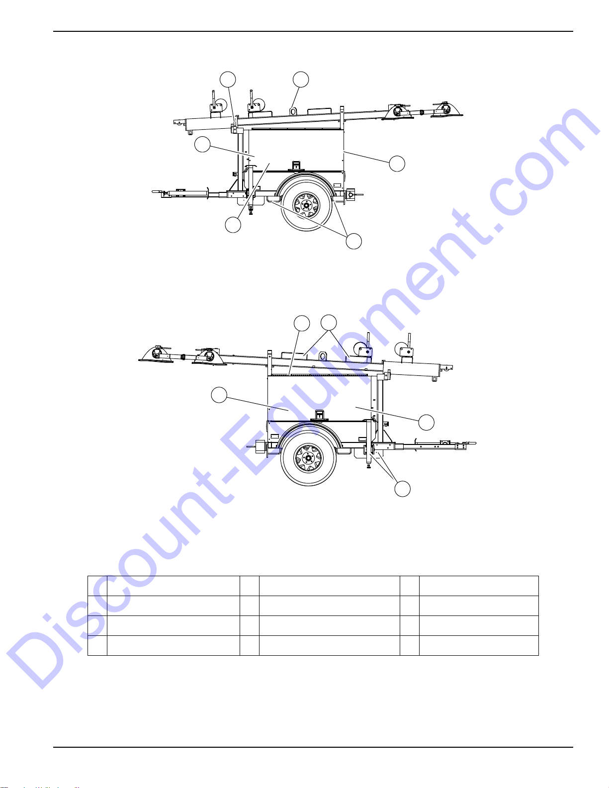
Component Locations
LEFT SIDE
RIGHT SIDE
004509
A B
C
D
E
F
G
H
I
J
K
Discount-Equipment.com
General Information
Figure 2-3. Component Locations
A Mast rotation knob E Battery I Fuel fill
B Central lifting point F Control box J Outriggers
C Engine exhaust G Radiator box K Engine access
D Lower Forklift pockets H Upper forklift pockets — —
Owner’s Manual for MLT Light Tower 11
Page 17

General Information
120V
240V
DC
BREAKER
TURN
MAIN
BREAKER
OFF
120V
BREAKER
MAIN
BREAKER
240V
BALLAST INDICATOR LIGHTS
MAST LIGHT SWITCHES
I
O
I
O
I
O
I
O
NEUTRAL BONDED TO FRAME
ON
ON
ON ON ON ON
GLOW PLUG
INDICATOR
OFF
RUN
START
GLOW
PLUG
400W 400W
Flagger Station Switches
A C
B
D
004548
F
E
G
H
I
J
K
Discount-Equipment.com
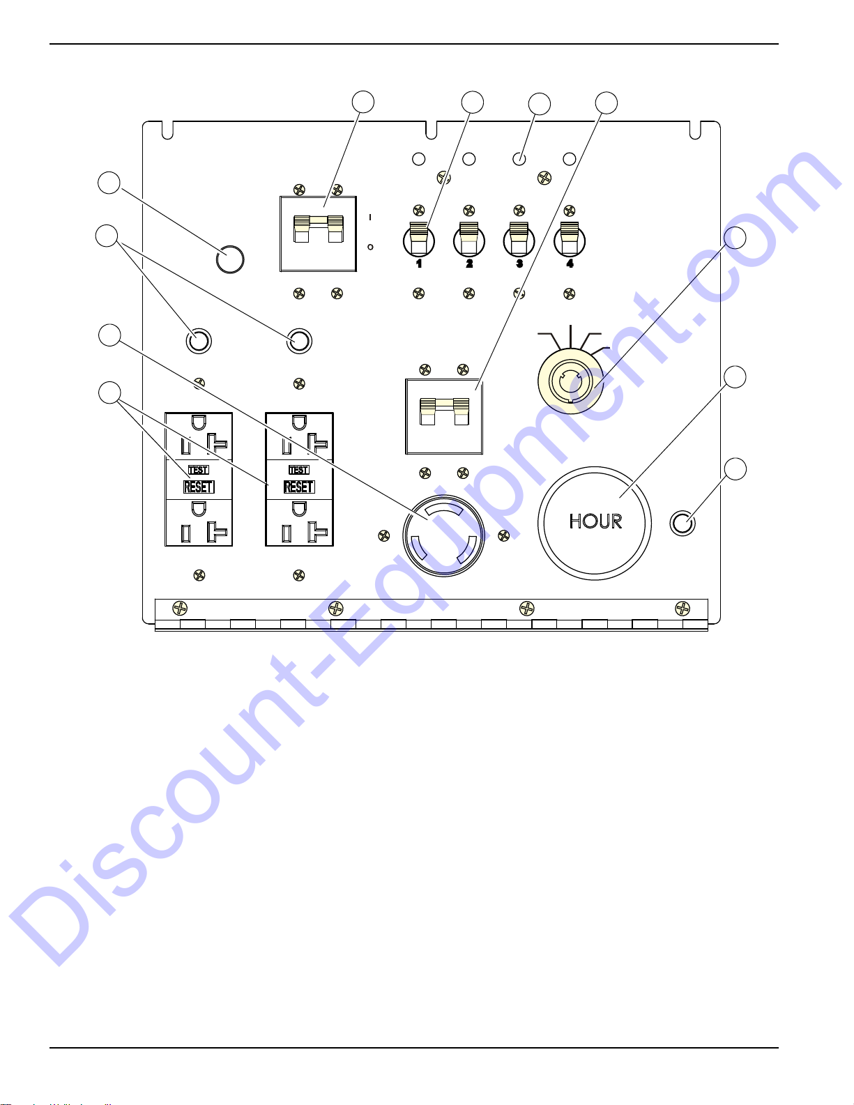
Control Panel - MLT5060M, MLT5060K
Figure 2-4. Control Panel
12 Owner’s Manual for MLT Light Tower
Page 18

Control Panel Features and Functions
Discount-Equipment.com
General Information
(A) Main Circuit Breaker
This 240V (30A) breaker will disconnect power to the
lights and auxiliary outlets. It will also disable the starting
circuit if engine starting is attempted when the main
breaker is on.
(B) Light Switches
One circuit breaker is supplied for each light.
(C) Ballast Indicator Lights
Indicates power from the ballast to each light
(D) Engine Starting Switch
Keyed switch operates glow plugs, starts and stops
engine.
(E) Glow Plug Indicator
Indicates operation of the engine glow plugs (Mitsubishi
engines only).
(F) Engine Hour Meter
Keeps track of engine hours for service.
.
(G) DC Circuit Breaker
Circuit breaker (10A) for the engine electrical system.
(H) 240V Twist-Lock Outlet
This 240V (30A) outlet supplies power for accessories
connected to the generator when the engine is running
and the main circuit breaker is switched to the ON (I)
position.
(I) 120V GFCI Outlets
This unit is equipped with one 120V (20A) GFCI outlet to
supply power for accessories connected to the generator
when the engine is running and the main circuit breaker
is switched ON (I).
(J) 120V Breaker
This 120V (20A) circuit breaker is supplied for the 120V
GFCI duplex outlets.
(K) Circuit Breaker Indicator Light
This light indicates that the main circuit breaker must be
opened (switched off) before starting the engine.
Owner’s Manual for MLT Light Tower 13
Page 19
General Information
004554
120V
120V
240V
DC
BREAKER
TURN
MAIN
BREAKER
OFF
120V
BREAKER
120V
BREAKER
MAIN
BREAKER
240V
BALLAST INDICATOR LIGHTS
MAST LIGHT SWITCHES
I
O
I
O
I
O
I
O
240V
BREAKER
NEUTRAL BONDED TO FRAME
I
O
ON
ON
ON ON ON ON
ON
ON
OFF
RUN
START
GLOW
PLUG
A
B
D
E
F
G
H
I
C
J
K
Discount-Equipment.com
Control Panel - MLT5080M, MLT5080K, MLT5080KCAN
Figure 2-5. Control Panel
14 Owner’s Manual for MLT Light Tower
Page 20

Control Panel Features and Functions
Discount-Equipment.com
General Information
(A) Main Circuit Breaker
This 240V (30A) breaker will disconnect power to the
lights and auxiliary outlets. It will also disable the starting
circuit if engine starting is attempted when the main
breaker is on.
(B) Light Switches
One circuit breaker is supplied for each light.
(C) Ballast Indicator Lights
Indicates power from the ballast to each light
(D) 240V Breaker
This 240V (30A) circuit breaker is supplied for the 240V
twist-lock receptacle.
(E) Engine Starting Switch
Keyed switch operates glow plugs, starts and stops
engine.
(F) Engine Hour Meter
Keeps track of engine hours for service.
.
(G) DC Circuit Breaker
Circuit breaker (10A) for the engine electrical system.
(H) 120V GFCI Outlets
This unit is equipped with one 120V (20A) GFCI outlet to
supply power for accessories connected to the generator
when the engine is running and the main circuit breaker
is switched ON (I)
(I) 240V Twist-Lock Outlet
This 240V (30A) outlet supplies power for accessories
connected to the generator when the engine is running
and the main circuit breaker is switched to the ON (I)
position.
(J) 120V Breaker
This 120V (20A) circuit breaker is supplied for the 120V
GFCI duplex outlets.
(K) Circuit Breaker Indicator Light
This light indicates that the main circuit breaker must be
opened (switched off) before starting the engine.
Owner’s Manual for MLT Light Tower 15
Page 21

Section 3: Operation
DETAIL C
DETAIL D
DETAIL G
DETAIL H
H
H
J
F
A
G
E
D
C
B
D
E
004697
(000260a)
High Voltage. Verify area above unit is clear
of overhead wires and obstructions. Contact
with high-voltage power lines will result in
death or serious injury.
DANGER
WARNING
(000297)
> 60 mph> 60 mph
Do not set up the unit if high winds
are expected. High winds can cause the
unit to tip or fall, causing severe injury
or machine damage.
Discount-Equipment.com
Light Tower Setup
Operation
Figure 3-1. Set Up Outriggers and Jacks
2. See Figure 3-1. Place the unit on firm ground that
is relatively flat (less than 5° slope), and then block
the wheels to keep it from moving (A).This will
make it easier to level the unit.
3. Pull the locking pin on the tongue jack (B) and
rotate the jack 90° until the spring loaded locking
pin snaps back into place. Rotate the jack handle
clockwise to raise the trailer tongue off the towing
vehicle.
4. A grounding stud (C) is located on the frame of the
1. For maximum light coverage, position the unit at
ground level or in a spot higher than the area being
illuminated by the lamps.
NOTE: The mast extends up to 30 ft (9.14 m).
Owner’s Manual for MLT Light Tower 17
5. Pull the locking pins (D) on the outriggers (E) and
6. Pull the locking pin on the rear jack (F) and rotate it
trailer near the trailer tongue. For grounding
requirements, follow National Electrical Code
(NEC), state, and local regulations.
pull each outrigger out until the spring loaded
locking pin snaps back into place. Pull the locking
pin on each outrigger jack and rotate each jack
180° so the jack pad is facing down and the spring
loaded locking pin snaps back into place.
90º until the spring loaded locking pin snaps into
Page 22

Operation
(000100a)
WARNING
Consult Manual. Read and understand manual
completely before using product. Failure to
completely understand manual and product
could result in death or serious injury.
DANGER
Electrocution. DO NOT use the unit if
electrical cord is cut or worn through. Doing
so will result in death or serious injury.
(000263a)
WARNING
Tipping hazard. Extend the outriggers and level the unit
before raising the mast. Keep the outriggers extended
while the mast is up. Failure to do so could cause the unit
to tip and fall and could result in death or serious injury.
(000266)
004698
B
G
A
H
E
C
B
D
F
Discount-Equipment.com
place. Turn the jack handle clockwise to start
leveling the trailer.
7. Rotate each jack handle clockwise to start leveling
the trailer. Adjust all four jacks by rotating their
handles clockwise until they are firmly in contact
with the ground (G).
8. Before raising the mast, it may be necessary to
adjust the lamps. The lamps may be adjusted up,
down, left or right by loosening the wing nuts on the
trunnion (H) and aiming the lamps in the desired
direction. Tighten the hardware completely and
make sure the lamps are connected to the junction
box (J).
Prestart Checklist
Before starting the unit, all items in the prestart checklist must be completed. This checklist applies to both
manual and remote starting of the unit.
Raising the Mast
1. Set up and level the unit. See Light Tower Setup.
DETAIL A
DETAIL C
DETAIL E
Verify all maintenance procedures are up to date. For
more information, refer to General Maintenance and
Basic Maintenance Schedule.
The unit must be level.
The unit must be dry. Look for water inside or near
the unit; dry if needed.
For grounding requirements, follow the National
Electrical Code (NEC), state, and local regulations.
Verify the Control Power switch is in the OFF (O)
position.
Verify all circuit breakers are in the OFF (O) position.
Inspect all electrical cords; repair or replace any that
are cut, worn, or bare.
Verify all winch cables are in good condition and
centered on each pulley. Do not use if cables are
kinked or beginning to unravel.
Check oil, coolant, and fuel levels. For more
information, refer to General Maintenance.
Verify battery connections are secure.
Turn the battery disconnect switch on, if equipped.
Check the engine fan belt tension and condition.
STOP
DETAIL G
Check the engine fan belt guard.
Check the engine exhaust system for loose or rusted
components.
Verify all covers are in place and secure.
18 Owner’s Manual for MLT Light Tower
2. See Figure 3-2. Remove mast cradle locking pin
from mast cradle (A).
Figure 3-2. Raising the Mast
Page 23

Operation
WARNING
Tipping hazard. Do not extend the mast beyond the
colored mark on the second mast section. The unit
can become unstable and tip or fall, causing injury.
(000262)
WARNING
Personal Injury. Stop immediately if the mast hangs
up or the winch cable develops slack. Excess slack
could cause the mast to collapse, resulting in personal
injury or equipment damage.
(000265)
(000279)
Personal injury or equipment damage. Do not raise
or lower the mast while the unit is operating.
Doing so can break the lenses and cause the
lamps to shatter.
WARNING
WARNING
Equipment Damage. Never start the engine with
circuit breakers switched on. Any load connected
to the generator at start up will cause severe
damage or destroy the generator.
(000368)
I
O
I
O
I
O
I
O
003791
GLOW
PLUG
OFF
RUN
START
003792
Discount-Equipment.com
3. Check the mast cables for excessive wear or
damage. Verify the cables are properly centered in
each pulley (B). Check the electrical cord for
damage.
4. Verify the area around the unit is clear before
raising the mast to vertical position.
5. Remove the safety pin from the mast lock bar (C).
Using the handle for the lower mast winch (D),
raise the mast until it is vertical and the tab on the
mast is positioned into the mast lock. The mast
lock bar should snap into place automatically.
Secure the lock with the safety pin (E).
6. After the mast is up and locked into place, use the
upper mast winch (F) to telescope the mast to the
desired height. Extend the mast slowly, making
sure the electrical cord is extending at the top
sections of the mast. Do not extend past the
colored mark (G).
IMPORTANT NOTE: Contact a Generac Mobile Products Authorized Service Dealer immediately if the
mast hangs up or the winch cable develops slack.
7. Rotate the mast by loosening the mast rotation
knob at the bottom of the mast (H). Turn the mast
until the lights face in the desired direction and
then tighten the knob.
1. See Figure 3-3. Verify the main circuit breaker and
individual circuit breakers for each of the lights are
OFF (O).
NOTE: If the red light on the control panel TURN MAIN
BREAKER OFF is illuminated when the key is turned to
the START position, the breaker is closed (switched on)
and must be turned OFF (O).
Starting the Unit
NOTE: If the engine was run out of fuel or the fuel tank
was drained, it may be necessary to bleed the fuel lines.
Refer to the engine operator’s manual supplied with the
unit.
Owner’s Manual for MLT Light Tower 19
Figure 3-3. Circuit Breakers in OFF (O) Position
2. See Figure 3-4. Turn the key on the Engine Start
switch to the right GLOW PLUG position and hold
the key in place for five seconds or until the glow
plug indicator turns red. (Kubota units do not have
a glow plug indicator.)
Figure 3-4. Activate Glow Plug
3. See Figure 3-5. Turn the key to the right START
position and hold it until the engine cranks and
starts running.
NOTE: For cold weather conditions, refer to the engine
operator’s manual for appropriate glow plug interval.
Page 24

Operation
GLOW
PLUG
OFF
RUN
START
003793
CAUTION
(000230)
Equipment Damage. Do not continuously crank
engine for more than ten seconds. Doing so will lead
to overdischarge of batteries and starter seizure.
GLOW
PLUG
OFF
RUN
START
003794
(000277)
WARNING
Burn hazard. Never operate lights with a
damaged or missing lens cover. Lamps are
hot and pressurized while in use. Unprotected
lamps can shatter, causing severe injury.
004548
A B C
Discount-Equipment.com
NOTE: If oil pressure is not obtained within 15 seconds
after the key is switched to the “RUN” position, the low oil
automatic shutdown will turn off the fuel supply, stopping
the engine. Check the oil level and turn the key to the
“OFF” position to reset the oil pressure timer before
attempting to restart the engine.
Figure 3-5. Crank Engine
4. See Figure 3-6. Release the key, it will move to the
RUN position.
exceeds normal operating temperature. Return the main
circuit breaker to the OFF position to reset the unit after
the cause of shutdown has been determined.
Light Operation
1. Verify the unit is on and running smoothly.
2. See Figure 3-7. Switch the main circuit breaker (A)
ON (I).
3. Switch the individual circuit breakers for the lights
(B) ON (I), one at a time.
4. The ballast indicator lights (C) will turn on and
continue to get brighter as the lights warm up, and
then remain on. This confirms power is coming
from the ballasts to the lights.
BALLAST INDICATOR LIGHTS
IOIOIOI
ON ON ON ON
MAST LIGHT SWITCHES
400W 400W
Flagger Station Switches
GLOW
PLUG
O
OFF
GLOW PLUG
RUN
INDICATOR
START
TURN
MAIN
BREAKER
OFF
BREAKER
MAIN
BREAKER
240V
ON
ON
120V
120V
240V
NEUTRAL BONDED TO FRAME
Figure 3-7. Light Switches and Breaker
NOTE: If an indicator light does not turn on, see
Troubleshooting or contact a Generac Mobile Products
Figure 3-6. Release Key
Authorized Service Dealer.
NOTE: The lights require a warm up period of 5-15
5. Once the engine is running, allow it to reach
normal operating temperature before switching on
any loads.
Automatic Shutdown
This unit is equipped with a low oil pressure and high
coolant temperature automatic shutdown system. This
system will automatically shut off the fuel supply to stop
minutes before they reach full output. If the lights are shut
down, they require a cool down period of approximately
ten minutes before they can be switched on again.
NOTE: The light tower uses four 1000W or 1050W
bulbs. When checking or replacing the bulbs, wipe them
with a clean cloth to avoid leaving any grease, oil residue
or fingerprints on the glass. Any residue can create a hot
spot on the bulb, causing premature bulb failure.
the engine if oil pressure drops too low or the engine
20 Owner’s Manual for MLT Light Tower
BREAKER
DC
Page 25

Auxiliary Outlets
(000278)
WARNING
Burn hazard. Lamps become extremely hot
while in use. Allow 10–15 minutes for cooling
before handling or lowering mast. Touching a
hot lens or fixture can cause severe burns.
120V
240V
BREAKER BREAKER
240V
BREAKER
NEUTRAL BONDED TO FRAME
I
O
004478
A
B
I
OIOIOIO
GLOW
PLUG
OFF
RUN
START
004550
Discount-Equipment.com
See Figure 3-8. Depending upon the model, the control
panel is equipped one or two 120V GFCI (A) and 240V
twist-lock (B) outlets for running accessories or tools from
the generator. Power is supplied to the receptacles any
time the engine is running and the main circuit breaker is
switched ON (I).
NOTE: Do not pull more than 1000W from each outlet
when the lights are on. This will overload the generator
and cause the main circuit breaker to trip. Should the
breaker trip, switch off the lights, remove some of the
load to the outlets and wait 10 minutes for the bulbs to
cool before turning them back on.
With all of the lights off, the full generator output may be
used with the 240V twist-lock outlet.
Operation
Voltage Regulator Option
Some units may be equipped with an electronic voltage
regulator. The electronic voltage regulator controls the
output of the generator by regulating the current into the
exciter field. The voltage regulator on your unit is
adjusted before shipment from the factory. Contact
Generac Mobile Products for additional information
before attempting to adjust the voltage regulator.
Engine Derating
All units are subject to derating for altitude and
temperature. Derating reduces the available power for
operating tools and accessories connected to the outlets.
For every increase in 1000 ft (305 m) of elevation, engine
performance for this unit typically drops between 2% and
4%. Also, engine performance decreases about 1% for
every 10ºF (5.6ºC) increase in ambient air temperature
over 72ºF (22ºC).
Shutting Down the Unit
Check with personnel using power supplied by the unit
and let them know the power is going to be turned off.
Make sure the power shutdown will not create any
hazards by accidentally turning off equipment that needs
to remain running (pumps, compressors, lights, etc.).
1. Remove all loads from the outlets.
2. See Figure 3-9. Switch the individual circuit
breakers for each light OFF (O).
3. Switch the main circuit breaker OFF (O).
4. Turn the Engine Start switch to the OFF (O)
position.
NOTE: For extended storage time, disconnect the
battery. For extended storage requirements, refer to the
engine operator’s manual.
Figure 3-8. Auxiliary Outlets
Wet Stacking
The unit is powered by a diesel engine. Diesel engines
are susceptible to wet stacking if lightly loaded. Wet
stacking occurs when an engine is run at less than 30%
of its full load capacity, causing unburned fuel to
accumulate in the exhaust system. Wet stacking can be
detected by continuous black exhaust when the unit is
under a constant load. It can also cause fouling of
injectors and buildup on engine valves. Diesel engines
operate properly when applied loads are between 30%
and 100% capacity. Appropriate generator sizing is
determined by the anticipated load. If the unit is in a wet
stack condition, load the unit heavily for five hours or until
the exhaust is clear.
Owner’s Manual for MLT Light Tower 21
Figure 3-9. Shutting Down
Page 26

Operation
(000278)
WARNING
Burn hazard. Lamps become extremely hot
while in use. Allow 10–15 minutes for cooling
before handling or lowering mast. Touching a
hot lens or fixture can cause severe burns.
WARNING
Personal Injury. Stop immediately if the mast hangs
up or the winch cable develops slack. Excess slack
could cause the mast to collapse, resulting in personal
injury or equipment damage.
(000265)
004687
Discount-Equipment.com
Lowering the Mast
1. Shut down the lights and engine. See Shutting
Down the Unit.
2. If the unit is going to be moved, it is recommended
that the mast is turned so the lights face the rear of
the unit. To rotate the mast:
a. Loosen the mast rotation knob.
b. Rotate the mast until the white arrows are
aligned and the metal stop tabs are touching.
c. Tighten the mast rotation knob.
3. Turn the upper mast winch handle
counterclockwise to collapse the mast to its lowest
position. Verify the coiled electrical cord does not
get caught in, or pinched by, the mast while it is
being lowered.
4. Insert the lights onto the light storage channel,
located on the inside of each door.
5. Orient the lights so the lenses are facing the rubber
seal on the inside of the door, as shown.
6. Secure the light fixtures with the wing nuts. Secure
the light cords to prevent damage to them.
NOTE: When installing the lights, verify the star washer
is in place between the trunnion and T-handle before
tightening.
Figure 3-10. Removing Lights
Towing the Unit
Once the engine is shut down and the mast and lights are
properly stowed, follow these steps to prepare the unit for
towing.
1. Raise the rear jack completely and release the
IMPORTANT NOTE: Contact a Generac Mobile
Products Authorized Service Dealer immediately if
the mast hangs up or the winch cable develops
slack.
4. Release the mast lock by pulling the safety pin on
the mast lock and pulling the lock bar free. Turn the
handle of the lower mast winch counterclockwise
until the mast rests in the transport cradle.
NOTE: Generac Mobile Products strongly recommends
that the lights be removed from the mast and stowed for
transportation. See Removing the Lights for
Transportation.
5. After the mast is completely down, insert the mast
cradle locking pin and secure it with the safety pin.
Removing the Lights for
Transportation
1. See Figure 3-10. Disconnect the power cords from
the junction box at the top of the mast.
2. Install the dust caps on the junction box.
3. Remove the lights from the mast by removing the
wing nut that holds the light fixture bracket to the
cross tube.
22 Owner’s Manual for MLT Light Tower
locking pin to rotate it up into the travel position.
Verify the locking pin snaps into place.
2. Raise the outrigger jacks completely and release
the jack locking pins to swing the jacks up into the
travel position. Verify the locking pins snap into
place. Release the outrigger locking pins and slide
the outriggers into the trailer frame until the locking
pins snap into place.
3. Use the tongue jack to raise or lower the trailer
onto the hitch of the towing vehicle. Lock the hitch
coupling and attach the safety chains or cables to
the vehicle. Remove the jack locking pin and rotate
the jack into the travel position. Replace the locking
pin.
NOTE: A film of grease on the coupler will extend
coupler life and eliminate squeaking. Wipe the coupler
clean and apply fresh grease each time the unit is towed.
4. To ensure proper operation of the jacks, lubricate
the grease fittings located on the leveling jacks.
Refer to Jack Maintenance. For maintenance
interval information, refer to Basic Maintenance
Schedule.
5. Connect any trailer wiring to the tow vehicle. Check
for proper operation of the directional and brake
lights.
Page 27

Operation
5
2
3
4
1
003754
B
A
C
C
004726
Discount-Equipment.com
6. Verify the enclosure is properly latched and the
mast cradle lock is in place.
7. Verify the doors are properly latched.
8. If driving over rough ground, remove the bulbs from
the light fixtures.
9. Check for proper inflation of the trailer tires. For
maximum tire pressures, refer to Specifications.
10. See Figure 3-11. Check the wheel lugs. Tighten or
replace any lugs that are loose or missing. If a tire
has been removed for axle service or replaced,
tighten the lugs, in the order shown, to the
following specifications:
6. Use the upper (B) or lower forklift pockets (C) with
care. Approach the unit as perpendicular as
possible to avoid any damage to the unit. Make
sure the mast winch handles or any other
obstructions are clear of the forklift tines before
lifting.
Figure 3-11. Tightening Wheel Lugs
a. Start all lug nuts by hand.
b. First pass: tighten to 20-25 ft-lbs (27-33 Nm).
c. Second pass: tighten to 50-60 ft-lbs (67-81 Nm).
d. Third pass: tighten to 90-120 ft-lbs (122-162 Nm).
NOTE: After the first road use, re-torque the lug nuts in
sequence.
11. Maximum recommended speed for highway towing
is 45 mph (72 km/h). Recommended off-road
towing speed is not to exceed 10 mph (16 km/h) or
less, depending on the terrain.
Figure 3-12. Lifting Point
Lifting the Unit
Follow these steps to prepare the unit for lifting:
1. Verify the equipment being used to lift the unit is in
2. See Figure 3-12. Close and lock all hoods and
3. Verify the cradle locking pin is in place.
4. When lifting the light tower and trailer, attach any
5. Always remain aware of people and objects around
Owner’s Manual for MLT Light Tower 23
good condition and has sufficient capacity. For
approximate weights, refer to Specifications.
doors and stow the lights as shown.
slings, chains or hooks directly to the central lifting
eye (A).
the unit while preparing, maneuvering, and lifting
the unit.
Page 28

Section 4: Maintenance
CAUTION
(000306)
Equipment Damage. Failure to perform a daily
inspection could result in damage to the unit.
004551
Discount-Equipment.com
Maintenance
Emissions Information
For warranty information, please refer to the diesel
engine manual supplied with this unit.
Daily Walk-Around Inspection
Perform a walk-around inspection of the unit every day
before starting the unit. Look for conditions that could
hinder performance or safety, such as (but not limited to):
• Oil, coolant and fuel leakage
• Blocked vents
• Loose or missing hardware
• Loose or broken electrical connections.
Inspect the fan belt for cracks, fraying, or stretching. Verify
the belt is properly seated in the pulley grooves. Replace
the belt according to the manufacturer’s recommendations.
General Maintenance
Poorly maintained equipment can become a safety
hazard. In order for the equipment to operate safely and
properly over a long period of time, periodic maintenance
and occasional repairs are necessary. DO NOT perform
routine service (oil and filter changes, cleaning, etc.)
unless all electrical components are shut off.
Regular maintenance will improve performance and
extend engine/equipment life. Generac Mobile Products
LLC recommends that all maintenance work be
performed by a Generac Mobile Products Authorized
Service Dealer. Regular maintenance, replacement or
repair of the emissions control devices and systems may
be performed by any repair shop or person of the owner’s
choosing. However, to obtain emissions control warranty
service free of charge, the work must be performed by a
Generac Mobile Products Authorized Service Dealer or
authorized engine dealer depending on the repair. See
the emissions warranty.
4. Attach a “Do Not Start” sign to the control panel.
This will notify everyone that the unit is being
serviced and will reduce the chance of someone
inadvertently trying to start the unit.
Cleaning the Unit
Always clean the Light Tower after each use to remove
dust, grease, mud, or spilled fuel or oil. Use soft, clean
rags to wipe the cabinet exterior and control panel. Lowpressure compressed air (less than 40 PSI [276 kPa])
can also be used to remove dust and debris from the
cabinet interior.
This unit contains sensitive electronic components that
can be damaged by high pressure and heat. Therefore:
• Do not wash the unit with a high pressure hose or
power washer.
• Do not wash the engine block or fuel tank with a
power washer or steam cleaner. Water may enter
the cabinet and collect in the generator windings or
other electrical parts, causing damage.
Inspecting the Unit
•
If the unit is stored outside, check for water inside
the cabinet and generator before each use. If wet,
dry the unit thoroughly before starting.
• Inspect condition of electrical cords. DO NOT use
the unit if insulation is cut or worn through.
• Verify winch cables are in good condition and
centered on each pulley. DO NOT use a cable that
is kinked or starting to unravel.
• Verify the safety pins for the mast lock rod and
mast lock bar are present and secured with a
chain. Check that the spring located in the mast
lock bar is not broken or missing. Check the
operation of the mast lock bar.
• See Figure 4-1. Verify correct mast cable routing.
Preparing for Service
Before servicing the unit, always follow the instructions
listed below.
1. Verify the key switch is in the OFF position.
2. Verify the circuit breakers are switched OFF (O).
3. Disconnect the negative (–) terminal on the battery.
Owner’s Manual for MLT Light Tower 25
Figure 4-1. Power Mast Cable Routing
• Verify the wheel lugs are present and properly
tightened. Refer to Towing Safety.
Page 29

Maintenance
Discount-Equipment.com
• Check the coolant level daily by inspecting the
level in coolant overflow jug located near the
radiator. Refer to the engine operator’s manual for
coolant recommendations and proper mixture.
Normal operating level is between the ‘full’ and
‘add’ markings on the overflow jug.
• AFTER ENGINE IS STOPPED AND
COMPLETELY COOL, coolant may be added
directly to the coolant overflow jug.
•
Check the oil level daily. Refer to the engine
operator’s manual for the appropriate oil specification.
Verify the oil is correct for special operating conditions
such as a change in season or climate.
•
DO NOT
the add mark on the dipstick.
•
Normal operating level is in the cross-hatch pattern
between the full and add markings on the dipstick.
•
A
dd oil only if the oil level is below the add mark on
the bottom of the cross-hatch pattern on the dipstick.
DO NOT OVERFILL
• Check the fuel level.
• If the unit is connected to a remote start or transfer
switch, make sure the remote switch is also off and
tagged.
start the unit if the engine oil level is below
the crankcase.
Basic Maintenance Schedule
Refer to the original equipment manufacturer’s operating
manual for a complete list of maintenance requirements.
Failure to comply with the procedures as described in the
engine operator’s manual will nullify the warranty,
decrease performance and cause equipment damage or
premature equipment failure. Maintenance records may
be required to complete a warranty request.
Use the schedule in the following table as a guide for
regular maintenance intervals. For additional or
replacement copies of the engine operator’s manual,
contact a Generac Mobile Products Authorized Service
Dealer.
NOTE: If the engine was run out of fuel or the fuel tank
was drained, it may be necessary to bleed the fuel lines.
Refer to the engine operator’s manual supplied with the
unit.
26 Owner’s Manual for MLT Light Tower
Page 30

Table 4-1. Basic Maintenance Guide (Mitsubishi)
Discount-Equipment.com
Maintenance
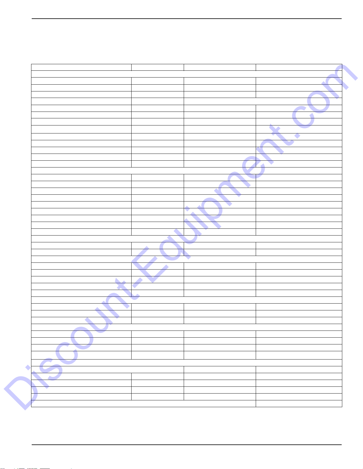
Item Daily
Check Oil Level
Check Coolant Level
Check Fuel Level
Check Tire Pressure
Check All Electrical Connections
Inspect Radiator Fins For Debris, Clean As Required
Inspect Light Tower Winch For Proper Operation
Fuel Tank - Drain Water
Check Air Cleaner
Replace Engine Oil And Oil Filter *
Belt And Belt Tension - Inspect And Adjust
Replace Fuel Filter
Drain And Clean Fuel Tank **
Check Glow Plugs
Lubricate Leveling Jacks
Bolts And Nuts On The Engine - Retighten *
Replace Heated Fuel Filter (If Equipped)
Inspect Engine Starting Battery
Air Cleaner Element - Clean, Check And Replace
Fuel System - Bleed Air
Water Sedimenter - Drain Water
50
Hours
250
Hours
400
Hours
500
Hours
1000
Hours
As
Required
* Perform after the initial 50 hours of operation, then on the regularly scheduled interval indicated in the schedule above.
** Certain conditions may require the fuel tank to be drained and cleaned more often. When operating in extremely
dusty conditions, clean the fuel tank as often as necessary.
Table 4-2. Basic Maintenance Guide (Kubota)
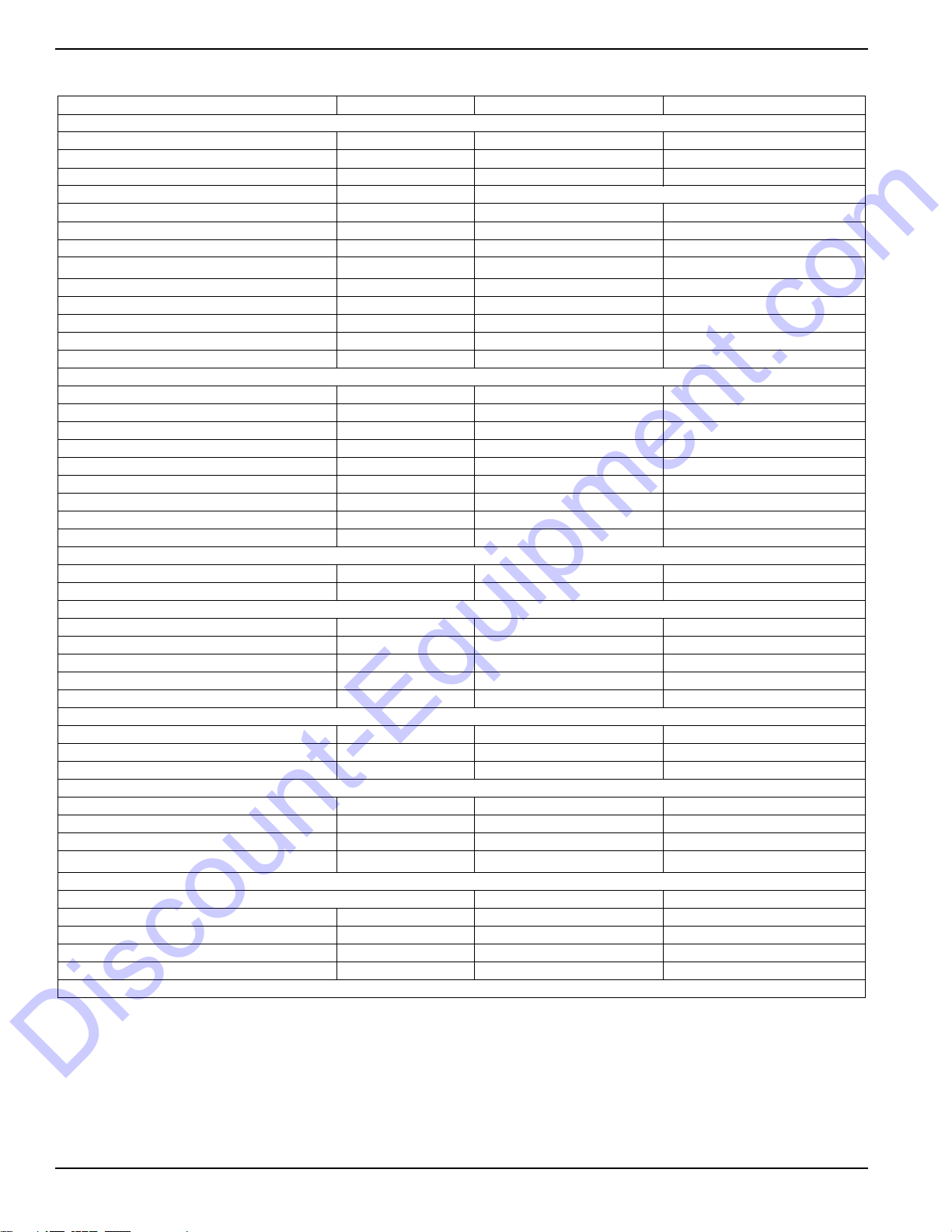
Item Daily
Check Oil Level
Check Coolant Level
Check Fuel Level
Check Tire Pressure
Check All Electrical Connections
Inspect Radiator Fins For Debris, Clean As Required
Inspect Light Tower Winch For Proper Operation
Check Fuel Pipes And Clamp Bands
Clean Air Cleaner Element
Clean Fuel Filter
Check Fan Belt Tightness
Drain Water Separator
Check Radiator Hoses And Clamp Bands
Change Engine Oil *
Check Intake Air Line
50
Hours
100
Hours
200
Hours
400
Hours
500
Hours1 Year
Owner’s Manual for MLT Light Tower 27
Page 31

Maintenance
A
B
C
004480
Discount-Equipment.com
Table 4-2. Basic Maintenance Guide (Kubota)
Item Daily
Replace Oil Filter Cartridge *
Replace Fuel Filter Cartridge
Clean Water Separator
Lubricate Leveling Jacks
Remove Sediment In Fuel Tank
Replace Fan Belt
Replace Air Filter Element **
* Change the engine oil and oil filter after the initial 50 hours of operation, then at the appropriate interval thereafter.
** Replace the air cleaner element yearly, or after six cleanings, whichever occurs first.
Winch Use, Operation and
50
Hours
2. The ratchet pawl pivot point must be kept
lubricated with a thin oil.
100
Hours
200
Hours
400
Hours
500
Hours1 Year
Maintenance
NOTE: Do not get oil or grease on the friction discs (A).
Prior to Use
Inspect rope or cable and replace if damaged.
•
• Check mounting hardware for proper tightness and
re-torque if necessary.
• Gears, ratchet pivot point and shaft bushings must
be kept lubricated with a thin film of oil or grease.
Operation
Raising the Lights:
1. The cable must be securely fastened to the winch
drum.
2. Verify the cable and cable attachments are not
damaged. Verify there is adequate safety factor of
at least three times the maximum load for all
components used. Contact Generac Mobile
Products to order a replacement cable if
necessary.
3. Referring to the “Cable In / Cable Out” decal on the
winch, turn handle according to the specified
direction to lift. The ratchet MUST make a loud
clicking sound while winding the cable.
Lowering the Lights:
Referring to the “Cable In / Cable Out” decal on the
winch, turn handle according to the specified direction to
lower. No clicking will be heard because the brake
system is activated.
Maintenance
The following procedures should be performed at least
annually:
1.See Figure 4-2.The gears and bushings of the winch
must be kept lubricated. Apply a thin film of grease
to the gear teeth (B), and oil the bushings as
needed (C).
Figure 4-2. Winch Maintenance
Optional Lower Radiator Hose
Heater Use and Maintenance
The following points should be followed when operating a
unit equipped with a lower radiator hose heater.
IMPORTANT NOTE: Improper use of the lower radiator
hose heater could result in serious personal injury.
• Verify that cooling system is full of a proper mixture
of water and engine coolant before each heater
use.
28 Owner’s Manual for MLT Light Tower
Page 32

• Heater is designed for all-night operation; how-
002306
B
B
B
B
B
A
A
A
002306
Discount-Equipment.com
ever, 2-5 hours of heating just prior to starting is
usually sufficient for proper engine starting.
• When heater is in operation, unit must be parked
in a level position to maintain the proper orientation
of the heater.
• Use only an undamaged extension cord, outdoors
rated, three-prong grounded 120VAC cord with a
minimum amperage rating of 10A. Connect to
properly grounded 120VAC, GFCI outlet only.
• Before starting the engine, unplug extension cord
from power first; then unplug heater cordset from
extension cord.
Trailer Wheel Bearings
The light tower is equipped with a grease zerk fitting to
allow lubrication of the wheel bearings without the need
to disassemble the axle hub. To lubricate the axle
bearings, remove the small rubber plug on the grease
cap, attach a standard grease gun fitting to the grease
zerk fitting and pump grease into the fitting until new
grease is visible around the nozzle of the grease gun.
Use only a high quality grease made specifically for
lubrication of wheel bearings. Wipe any excess grease
from the hub with a clean cloth and replace the rubber
plug when finished. The minimum recommended
lubrication is every 12 months or 12,000 miles (19,312
km); more frequent lubrication may be required under
extremely dusty or damp operating conditions.
Maintenance
Figure 4-3. Jack Maintenance
Jack Maintenance
The following procedures should be performed at least
annually: For side-wind models, the internal gearing and
bushings of the jack must be kept lubricated.
• See Figure 4-3. Apply a small amount of
automotive grease (A) to the internal gearing by
removing the jack cover, or if equipped, use a
needle nose applicator or standard grease gun on
the lubrication point found on the side of the jack
near the crank. Rotate the jack handle to distribute
the grease evenly.
• A lightweight oil (B) must be applied to the handle
unit at both sides of the tube for side-wind models.
• If equipped, the axle bolt and nut assembly of the
caster wheel must also be lubricated with the same
lightweight oil.
• For top-wind models, apply a lightweight oil to the
screw stem.
Owner’s Manual for MLT Light Tower 29
Page 33

Section 5: Troubleshooting
(000139)
WARNING
Risk of burns. Allow engine to cool before
draining oil or coolant. Failure to do so could
result in death or serious injury.
Discount-Equipment.com
General Troubleshooting
Some of the more common problems are listed in the
table below. This information is intended to be a check or
verification that simple causes can be located and fixed.
It does not cover all types of problems. Refer to the OEM
engine operator’s manual for additional troubleshooting
information. Procedures that require in-depth knowledge
or skills should be referred to a Generac Mobile Products
Authorized Service Dealer.
Table 5-1. General Troubleshooting Guide
Troubleshooting
Problem Possible Cause Solution
Low oil level Verify oil level on dipstick. Add oil, if needed.
Low oil pressure
shutdown
High coolant
temperature shutdown
Unit cranks, but will not
start
Oil leaking from engine Visually inspect the engine for leaks.
Oil pressure switch failure
Low coolant level
Blockage in radiator
Leakage in coolant hoses,
engine block, or water
pump
Fuel level low
Restricted air filter
Refer to OEM engine operator’s manual to identify corrective
action.
Add coolant if needed. Allow engine to cool, then check coolant
level in radiator. Restart engine and check coolant temperature.
Stop engine immediately if coolant temperature is 210°F (99°C)
or more.
Inspect radiator shroud and ducting for blockage and remove
any foreign matter.
Inspect for visible leaks. Verify tension of water pump serpentine
drive belt.
Remove load on generator and restart engine. Verify coolant
temperature and shut engine down immediately if it starts to
overheat. Refer to the OEM engine operator’s manual for
additional information on engine overheating.
Check fuel level in tank.
Verify fuel pump operation.
Inspect air filter for blockage.
Refer to OEM engine operator’s manual for additional
information.
Overspeed or
Underspeed Shutdown
Frequency setting incorrect Disconnect all loads and restart unit. Read frequency (Hz) in the
LCD window on controller. Frequency should read 60 Hz.
If frequency is above 60 Hz, engine speed will need to be
adjusted. Refer to the engine operator’s manual for throttle
adjustment information.
Owner’s Manual for MLT Light Tower 31
Page 34

Troubleshooting
(000278)
WARNING
Burn hazard. Lamps become extremely hot
while in use. Allow 10–15 minutes for cooling
before handling or lowering mast. Touching a
hot lens or fixture can cause severe burns.
(000187)
WARNING
Electrocution. Potentially lethal voltages are generated
by this equipment. Render the equipment safe before
attempting repairs or maintenance. Failure to do so
could result in death or serious injury.
Discount-Equipment.com
Troubleshooting the Lights
Problem Possible Cause Solution
Mast Lights Off, but
Ballast Indicators
on Control Panel
are On.
Light fixture is too hot.
Faulty lamp connection.
Lamp broken
IMPORTANT NOTE: Only a qualified electrician
should troubleshoot or repair electrical problems
occurring in this equipment.
Allow light to cool 10-15 minutes before restarting.
Check that the lamp is tight in the socket.
Check for broken arc tube or outer lamp jacket, broken or loose
components in lamp envelope, or blackening/deposits inside tube.
Mast Lights Off,
and Ballast
Indicators on the
Control Panel are
Off.
Mast Lights On But
the Light Output is
Low
Loose lighting
connections
Damaged or loose
electrical cord
Loose lighting
connections
Generator output
incorrect.
Low transformer output.
Fixture and/or lens is
dirty.
Lamp worn due to
normal use
Damaged or loose
electrical connections
Check the connections inside the mast junction box and each mast light
housing/socket.
Check the mast electrical cord for damage and check the cord connections
inside the control box.
Check the connections inside the control box and inside each ballast box.
Check the incoming voltage to the ballast by checking the available voltage
on the GFCI receptacle. Incoming voltage should be 120V +/- 5V. If voltage
is incorrect, the engine speed may need to be adjusted or generator may
require service.
The voltage from the transformer should read approximately 400VAC as
the light “strikes” (induces an arc), then drop and slowly rise back up to
stabilize at 240-260VAC. On hard wired models,
remove the mast junction box cover and insert the wire probes into the
connector blocks for the light and ground. If proper voltage is not achieved,
perform capacitor check to determine if the capacitor or coil needs
to be replaced.
Clean reflective surface inside fixture and both inside and outside surface
of glass lens. Use mild soap and water to clean lens. Other chemicals may
have an adverse effect on the glass.
Replace lamp.
Check the mast coil cord, mast junction box and mast light connections.
Generator output
incorrect.
Low transformer output
32 Owner’s Manual for MLT Light Tower
Check the incoming voltage to the ballast. Incoming voltage should be
120V +/-5V. If the voltage is incorrect, the engine speed may need to be
adjusted or the generator may require service.
The voltage from the transformer should read approximately 400VAC as the
light “strikes” (induces an arc), then drop and slowly rise back up to stabilize
at 240-260VAC. On hard wired models, remove the mast junction box cover
and insert the wire probes into the connector blocks for the light and ground.
If proper voltage is not achieved, perform capacitor check to determine if the
capacitor or coil needs to be replaced.
Page 35

Section 6: Wiring Diagrams
00768
1
3
2
4
Discount-Equipment.com
Mast Junction Box Wiring and Light Connections
Wiring Diagrams
Owner’s Manual for MLT Light Tower 33
Page 36

Wiring Diagrams
Discount-Equipment.com
AC Wiring Diagram
GN
GN
3
WT
WT
1
4
BK
BK
GN
GN
2
BK
BK
YL
BL
RD
WT
BK
GN
WT/BK OR BN
YL
3
..
BK
RD
2
TRANSFORMER 4
CAP 3
WT
WT
14
CAP 4
14
CAP 2 CAP 1
MAST CABLE
GY
YL
3 1
BL
23
BK
BK
RD
2
RD
YL
RD
2
BK
GY
BL
23
BK
YL
BK
RD
2
RD
..
TRANSFORMER 3
3 1
..
TRANSFORMER 2
3 1
..
1
TRANSFORMER 1
GN
GY
TWIST
30 AMP
RD
CB7
8KW UNITS
ONLY
TO
XZ
BK
30A
BK
GND
BAR
GFCI
CB6
LED BOARD
BL
BL
BK
BK
YL
BL
WT
BK
RD
RD
YL
1
TO
GND
BAR
WT
GN
TO
BAR
GND
GY
RD
BL
RD
2
RD
GY
BK
34567
GFCI
BK
CB5
RD RD
20A
8KW UNITS ONLY
20A
BK
BK
BK
BK
BK
RD
RD
RD
9
8
11
10
12
RD
BK
RD
BK
15 A
CB1
15 A
CB1
15 A
CB1
15 A
CB1
RD
BK BK
RD
BK
RD
RD
BK
RD
MAIN
GEN
N
TO
BAR
GND
RD
WT
WT
1
WT
WT
2
34567
WT
WT
WT
WT
9
8
10
GN
TO
BAR
GND
90347_E_06.21.14
34 Owner’s Manual for MLT Light Tower
Page 37

DC Wiring Diagram—Mitsubishi
RED (PULL)
WHT (HOLD)
BLU (COM)
SOLENOID
RED/YEL
VIO/YEL
BLK/YEL
BLK/YEL
RED/WHT
STARTER SWITCH
HOUR
VIO/YEL
VIO/YEL
BLK/WHT
BLK/WHT
RED
BLK
FUEL
PUMP
10 AMP
CIRCUIT
BREAKER
OIL
PRESSURE
WARNING
SWITCH (N.C.)
SWITCH (N.O.)
WARNING
OVERHEAT
12V BATTERY
STARTER
RELAY
TIME DELAY
GRY/BLU
GRY/VIO
VI/YL
RED
BLK
CONTROL
RESISTANCE
BLK/YEL
GLOW PLUGS
AUX SWITCH
MAIN BREAKER
RD/VI
ALTERNATOR
WARNING LIGHT
"TURN MAIN
BREAKER OFF"
BLK/WHT BLK
RED/YEL
ORG/YEL
RD/VI
RED/VIO
N/C
N/O
-
+
COM
90340_C_04.23.13
Discount-Equipment.com
Wiring Diagrams
Owner’s Manual for MLT Light Tower 35
Page 38

Wiring Diagrams
Discount-Equipment.com
DC Wiring Diagram—Kubota
After Serial Number 0900090
BK/WT
BK/YL
HOUR
BK/WT
VI/YL
RD/VI
RD/VI
VI/YL
YLBK
STARTER SWITCH
RD
10 AMP
CIRCUIT
BREAKER
N/O
COM
BK
FUEL
PUMP
OIL
WARNING
PRESSURE
SWITCH (N.C.)
GY/VI
GY/BL
WARNING
OVERHEAT
SWITCH (N.O.)
RD
N/C
-
+
RELAY
TIME DELAY
12V BATTERY
VI/YL
RD/YL
(PULL)
(HOLD)
SOLENOID
RD/WT
BK/YL
GLOW PLUGS
RD/YL
OR/YL
AUX SWITCH
MAIN BREAKER
BK
"TURN MAIN
WARNING LIGHT
RD
STARTER
BK
RD/VI
ALTERNATOR
RD/VI
BK/WT
BREAKER OFF"
90339_E_01.30.14
36 Owner’s Manual for MLT Light Tower
Page 39

DC Wiring Diagrams for Optional Equipment
Discount-Equipment.com
BLK
RED
-
+
12 V
BATTERY
HEATED FUEL FILTER
BATTERY CHARGER
EDISON PLUG
BLU
BRN
YEL/GRN
16/3
BATTERY
CHARGER
RD/BK
RD/WT
2
R
BK/WT
1
R
BK
R
B
ACC
B
C
STARTER SWITCH
25A
87
FUSE
8586
NCCOM
87A
RD/VI
Wiring Diagrams
SPLICE
BK
TO
GND
BAR
30
RD/BK
NO-
TO CNTRL
PANEL START
SOL WIRE
TO
GND
BAR
TO MAIN
BREAKER AUX
SWITCH NC PIN
21
OR/YL1
ESTOP
RD/WT
BK/WT1
TO
GND
BAR
BK
BK
RPM
SENSOR
WT
BK/WT
-
+
12 V
BATTERY
BK/WT2
43
GY
CIRCUIT
BREAKER
RD
OR/YL2
20A
POSITIVE AIR SHUTDOWN 6-20KW
SOLENOID
PASS
OPT
SW
RPM
PWR
GND
NCCOM
BK1
GND
TIME
DELAY
+
SOL
PNK
PASS
NO-
SPLICE
SPLICE
BATTERY
DISCONNECT
-
+
12 V
BATTERY
BK
WT
RD
TIME
FLOAT
SWITCH
LOW FUEL SHUTDOWN
BK/WT
DELAY
+
WT/VI
ALT CONFIG
MTB PIN 12
INTERIOR LIGHT BATTERY DISCONNECT
10A
FUSE
2
R
1
R
R
B
B
STARTER SWITCH
LIGHT
ACC
C
90323_K_06.04.14
Owner’s Manual for MLT Light Tower 37
Page 40

Wiring Diagrams
Discount-Equipment.com
Trailer Lights Wiring
BK
WT
BN
YL
PLUG
GN
TRAILER
AMBER
MARKER
LAMP
BK
SPLICE
SPLICE
WT
BN
MARKER
RED
BK
BK
SPADE
LAMP
SPADE
RING
WT
RIGHT
TAIL/TURN
BK
RD
SPLICE
GN
LAMP
WT
SPLICE
SPLICE
BK
BK
LAMP
AMBER
MARKER
BN
WT
BN
SPADE
BK
RED
BN
WT
SPADE
BK
LAMP
MARKER
YL
SPADE
RDWTBK
LEFT
LAMP
TAIL/TURN
BN
WT
SPADE
SPADE
BK
LICENSE
WT
90341_B_12.20.13
LAMP
PLATE
38 Owner’s Manual for MLT Light Tower
Page 41

Discount-Equipment.com is your online resource for commercial and industrial
Discount-Equipment.com
quality parts and equipment sales.
Locations:
Florida (West Palm Beach): 561-964-4949
Outside Florida TOLL FREE: 877-690-3101
Need parts? Check out our website at www.discount-equipment.com
Can’t find what you need?
Click on this link: http://www.discount-equipment.com/category/5443-parts/ and fill out
the request form.
Please have the machine model and serial number available in order to help us get
you the correct parts. One of our experienced staff members will get back to you with
a quote for the right part that your machine needs.
We sell worldwide for the br
Diamond
Chicago Pneumatic, Allmand Brothers, Essick, Miller Spreader, Skyjack, Lull, Skytrak,
Tsurumi, Husquvarna/Target, Whiteman-Concrete/Mortar, Stow-Concrete/Mortar, Baldor,
Wacker, Sakai, Snorkel, Upright, Mi-T-M, Sullair, Neal, Basic, Dynapac, MBW, Weber,
Bartell, Bennar Newman, Haulotte, Ditch Runner, Blaw-Knox, Himoinsa, Best, Buddy,
Crown, Edco, Wyco, Bomag, Laymor, Terremite, Barreto, EZ Trench, Takeuchi, Basic, Bil-
Jax, Curtis, Gehl, Heli, Honda, ICS/PowerGrit, Puckett, Waldon, ASV, IHI, Partner, Imer,
Clipper, MMD, Koshin, Rice, Gorman Rupp, CH&E, Cat Pumps, Comet, General Pump,
Giant,AMida, Coleman, NAC, Gradall, Square Shooter, Kent, Stanley, Tamco, Toku, Hatz,
Kohler, Robin, Wisconsin, Northrock, Oztec, Toker TK, Rol-Air, Small Line, Wanco, Yanmar
Products, Magnum, Airman, Mustang, Power Blanket, Nifty Lift, Atlas Copco,
ands: Genie, Terex, JLG, MultiQuip, Mayco, Toro/Stone,
Page 42

www.discount-equipment.com
Discount-Equipment.com
Part No. 10413 Rev. L 3/9/17
©2017 Generac Mobile Products
All rights reserved.
Specifications are subject to change without notice.
No reproduction allowed in any form without prior written
consent from Generac Mobile Products.
 Loading...