

Page 1
GENERAC
Owner'siVl
GPSeriesPortabJeGenerator
Page 2
introduction.............................................................1
Maintenance.........................................................12
ReadthisManual Thoroughly.................................1
Safety Rules...........................................................1
StandardsIndex.............................................................3
Generalinformation................................................4
1.1 Unpacking......................................................................4
1.2 Assembly.......................................................................4
1.3 EmissionsInformation....................................................5
Operation................................................................5
2.1 Knowthe Generator.......................................................5
2.2 Hourmeter......................................................................6
2.3 ConnectionPlugs...........................................................6
2.4 Howto Usethe Generator..............................................7
2.5 Don'tOverloadthe Generator..........................................8
2.6 WattageReferenceGuide...............................................9
2.7 BeforeStartingthe Generator.........................................9
2.8 Starting Pull Start Engines............................................10
2.9 Starting ElectricStart Engines......................................11
2.10 Stoppingthe Engine.....................................................11
2.11 LowOil LevelShutdownSystem..................................11
2.12 Chargingthe Battery(ElectricStart UnitsOnly).............12
3.1 PerformingScheduledMaintenance.............................12
3.2 MaintenanceSchedule.................................................12
3.3 ProductSpecifications..................................................12
3.4 GeneralRecommendations...........................................13
3.5 ServiceAir Filter...........................................................14
3.6 ValveClearance............................................................15
3.7 General........................................................................15
3.8 Long TermStorage.......................................................15
3.9 OtherStorageTips.......................................................15
Troubleshooting....................................................16
4.1 TroubleshootingGuide..................................................16
Notes....................................................................17
MANUALDELPROPIETARIO.....................19
MANUELD'ENTRETIEN......................................39
WARNING!
California Proposition 65
Engine exhaust and some of its constituents are known to the state of California to cause cancer,
birth defects, and other reproductive harm.
WARNING!
California Proposition 65
This product contains or emits chemicals known to the state of California to cause cancer,
birth defects, and other reproductive harm.
Page 3
iNTRODUCTiON
Thankyou for purchasingthis model by GeneracPowerSystems,
Inc. This model is a compact, high performance, air-cooled,
engine driven generatordesigned to supply electrical power to
operateelectrical loads where no utility power is availableor in
placeof utility dueto a poweroutage.
SAFETYRULES
Throughoutthis publication,and on tags and decals affixedto the
generator,DANGER,WARNING,CAUTIONand NOTEblocks are
usedto alert personnelto special instructions about a particular
operation that may be hazardous if performed incorrectly or
carelessly.Observethem carefully.Their definitionsareasfollows:
BEADTHiSMANUALTHOROUGHLY
If anyportion ofthis manualis not understood,contactthenearest
AuthorizedDealerfor starting, operatingandservicingprocedures.
The operator is responsible for proper and safe use of the
equipment.We strongly recommend that the operator read this
manualandthoroughlyunderstandallinstructions beforeusingthe
equipment.Wealsostronglyrecommendinstructingother usersto
properlystart andoperatethe unit.This preparesthemifthey need
to operatetheequipmentin an emergency.Savethese instructions
for future reference.If you loan this deviceto someone,ALWAYS
loanthese instructionsto the individualas well.
Thegeneratorcan operatesafely,efficiently and reliablyonly if it
is properlylocated, operatedandmaintained.Before operatingor
servicingthe generator:
• Becomefamiliar with and strictly adhereto all local, stateand
nationalcodes and regulations.
• Study all safety warnings in this manual and on the product
carefully.
• Becomefamiliarwith thismanualandthe unit beforeuse.
Themanufacturercannot anticipateevery possible circumstance
that might involvea hazard.The warnings inthis manual,and on
tags and decals affixedto the unit are, therefore,not all inclusive.
If using a procedure,work method or operatingtechniquethat the
manufacturerdoes not specifically recommend,ensurethat it is
safe for others. Also make sure the procedure,work method or
operatingtechniqueutilizeddoes not renderthe generatorunsafe.
THE INFORMATIONCONTAINEDHEREIN WAS BASED ON
MACHINESIN PRODUCTIONAT THE TIME OF PUBLICATION.
GENERACRESERVESTHERIGHTTOMODIFYTHISMANUALAT
ANYTIME.
INDICATESAHAZARDOUSSiTUATiONORACTIONWHICH,IF
NOTAVOIDED,WILLRESULTIN DEATHORSERIOUSINJURY.
Indicatesa hazardoussituationor action which,if not
avoided, couldresultin deathor seriousinjury.
_CAUTION!
Indicatesa hazardoussituationoraction which,if not
avoided, couldresultin minoror moderateinjury.
NOTE:
Notescontainadditionalinformationimportantto a procedure
and will be foundwithinthe regular textbody ofthis manual.
These safety warnings cannot eliminate the hazardsthat they
indicate. Common sense and strict compliancewith the special
instructionswhile performingthe action or serviceareessentialto
preventingaccidents.
Four commonly used safety symbols accompany the DANGER,
WARNINGand CAUTIONblocks. The type of information each
indicatesis as follows:
,_This symbol points out important safety
information that, if not followed, could
endanger personal safety and/or property of
others.
This symbol points out potential explosion
hazard.
i/_This symbol points out potential fire hazard.
This symbol points out potential electrical
shock hazard.
Page 4
GENERAL HAZARDS
EXHAUST & LOCATIONHAZARDS
• NEVERoperatein an enclosed area, in a vehicle, or indoors
EVENIFdoors and windows areopen.
• For safety reasons, the manufacturer recommendsthat the
maintenanceof this equipmentis carried out by an Authorized
Dealer.Inspectthe generatorregularly,and contactthe nearest
AuthorizedDealerfor parts needingrepair or replacement.
• Operategeneratoronly on levelsurfacesandwhereit will notbe
exposedto excessivemoisture,dirt, dust or corrosive vapors.
• Keephands, feet, clothing, etc., away from drive belts, fans,
and othermoving parts. Neverremoveany fan guardor shield
whilethe unit is operating.
• Certain parts of the generator get extremely hot during
operation. Keep clear of the generator until it has cooled to
avoidsevereburns.
• Do NOToperategeneratorinthe rain.
• Do not alter the construction of the generator or change
controlswhich might createan unsafeoperatingcondition.
• Never start or stop the unit with electrical loads connected
to receptaclesAND with connecteddevicesturned ON. Start
the engine and let it stabilize before connecting electrical
loads. Disconnectall electricalloadsbefore shuttingdown the
generator.
• Do notinsert objectsthrough unit's coolingslots.
• When working on this equipment, remain alert at all times.
Never work on the equipment when physically or mentally
fatigued.
• Neverusethe generatoror anyof its partsas a step. Stepping
on the unit can stress and break parts, and may result in
dangerousoperating conditions from leakingexhaust gases,
fuel leakage,oil leakage,etc.
NOTE:
This generatormaybe equippedwith a spark arrestormuffler.
The spark arrestor must be maintained in effective working
orderby theowner/operator.In theState of California, a spark
arrestor is required by law (Section4442 of the California
PublicResources Code). Other states may havesimilar laws.
Federal lawsapply on federallands.
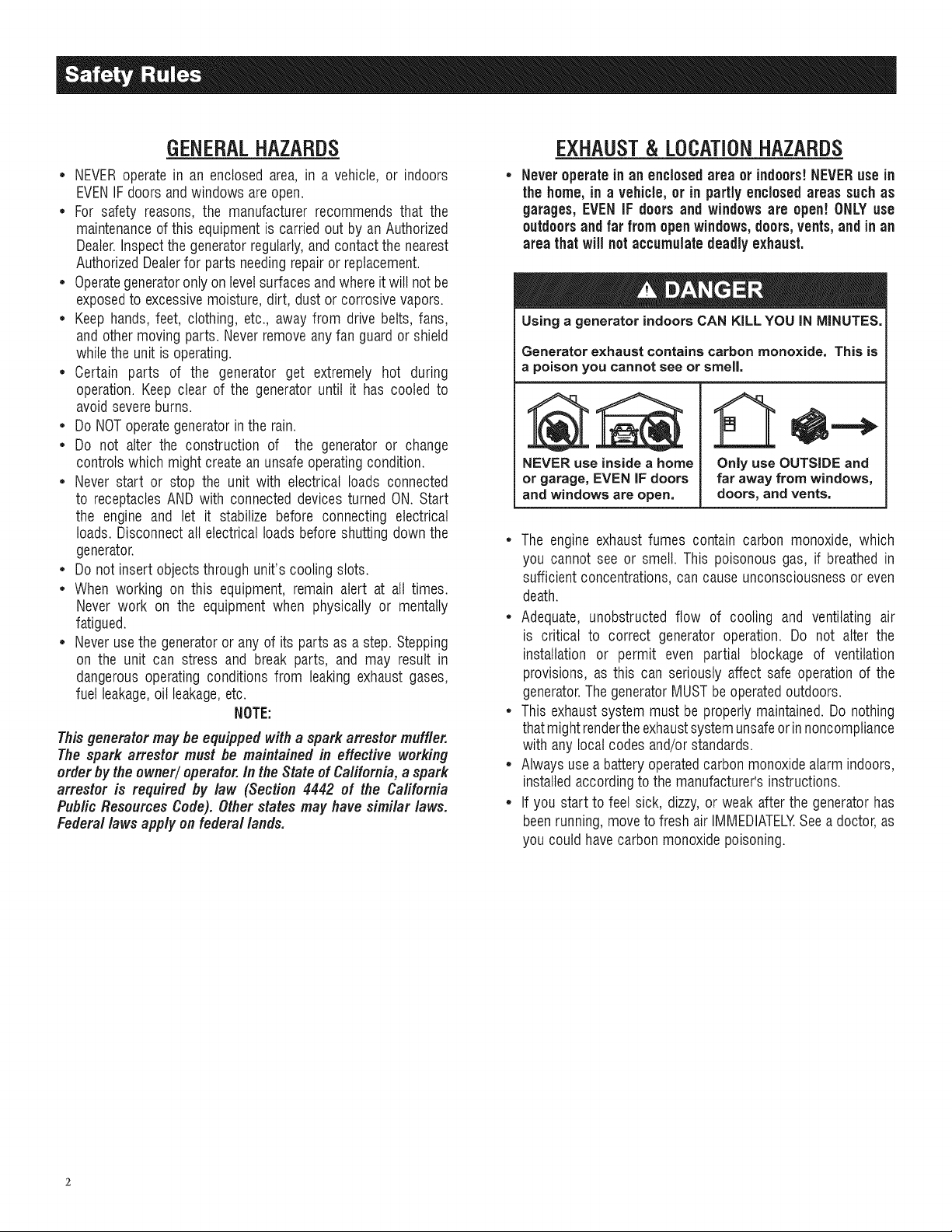
• Never operate in an enclosed area or indoors!NEVERuse in
the home,in a vehicle, or in partly enclosedareas suchas
garages,EVENIF doors and windowsare open! ONLYuse
outdoors and far from open windows,doors, vents,andinan
areathat will notaccumulate deadly exhaust.
Using a generator indoors CAN KILL YOU iN MINUTES.
Generator exhaust contains carbon monoxide. This is
a poison you cannot see or smell.
NEVER use insidea home
or garage, EVEN IF doors
and windows are open,
• The engineexhaustfumes contain carbon monoxide, which
you cannot see or smell. This poisonous gas, if breathed in
sufficientconcentrations,can cause unconsciousnessor even
death.
• Adequate, unobstructed flow of cooling and ventilating air
is critical to correct generator operation. Do not alter the
installation or permit even partial blockage of ventilation
provisions, as this can seriously affect safe operationof the
generator.ThegeneratorMUSTbeoperatedoutdoors.
• This exhaustsystem must be properlymaintained.Do nothing
thatmightrendertheexhaustsystemunsafeorinnoncompliance
with any localcodes and/or standards.
• Alwaysuse a battery operatedcarbonmonoxidealarmindoors,
installedaccordingto themanufacturer'sinstructions.
• If you start to feel sick, dizzy,or weak afterthe generatorhas
beenrunning,move tofresh air IMMEDIATELYSeea doctor,as
you couldhave carbonmonoxidepoisoning.
Only use OUTSIDE and
far away from windows,
doors, and vents.
Page 5

ELECTRICALHAZARDS
• The generator produces dangerously high voltage when in
operation.Avoidcontactwith barewires, terminals,connections,
etc., whilethe unitis running, even on equipmentconnectedto
thegenerator.Ensureallappropriatecovers,guardsandbarriers
are in place beforeoperatingthe generator.
• Never handle any kind of electrical cord or device while
standingin water,whilebarefootor while handsor feet arewet.
DANGEROUSELECTRICALSHOCKMAYRESULT.
• TheNationalElectricCode(NEC)requirestheframeandexternal
electrically conductive parts of the generator be properly
connectedto an approvedearth ground. Localelectricalcodes
may also require proper grounding of the generator.Consult
with a localelectricianfor groundingrequirementsin the area.
• Use a ground fault circuit interrupter in any damp or highly
conductivearea(such as metaldecking or steelwork).
• Do not useworn, bare,frayed or otherwisedamagedelectrical
cord setswith the generator.
• Beforeperforminganymaintenanceonthegenerator,disconnect
the engine starting battery (if equipped)to prevent accidental
start up. Disconnectthe cable from the battery post indicated
by a NEGATIVE,NEGor (-) first. Reconnectthatcable last.
• In caseof accidentcausedby electricshock, immediatelyshut
down the source of electrical power. If this is not possible,
attempt to free the victim from the live conductor. AVOID
DIRECTCONTACTWITH THE VICTIM. Use a non-conducting
implement,such asa ropeor board,to free thevictim fromthe
live conductor.If the victim is unconscious,applyfirst aid and
getimmediatemedical help.
• Do notinsert objectsthrough unit's cooling slots.
• Never operate the generator if connected electrical devices
overheat,if electricaloutputislost, if engineor generatorsparks
or if flames or smoke are observedwhileunit is running.
• Keepafire extinguishernearthe generatoratall times.
STANDARDS/NDEX
1. NationalFireProtectionAssociation(NFPA)70:TheNATIONAL
ELECTRICCODE(NEC)availablefrom www.nfpa.org
2. NationalFire ProtectionAssociation (NFPA)5000: BUILDING
CONSTRUCTIONAND SAFETYCODEavailable from www.
nfpa.org
3. InternationalBuildingCodeavailablefrom www.iccsafe.org
4. Agricultural Wiring Handbookavailablefrom www.rerc.org ,
Rural ElectricityResourceCouncil RO.Box 309 Wilmington,
OH45177=0309
5. ASAEEP-364.2Installationand Maintenanceof FarmStandby
Electric Power available from www.asabe.org, American
Society of Agricultural & Biological Engineers2950 Niles
Road,St. Joseph,MI 49085
This list is not all inclusive.Checkwith theAuthority HavingLocal
Jurisdiction (AHJ)for any localcodes or standardswhich maybe
applicableto your jurisdiction.
MODELNO:
SERIALNO:
FIREHAZARDS
• GasolineishighlyFLAMMABLEanditsvaporsareEXPLOSIVE.
Never permit smoking,open flames, sparksor heat in the
vicinitywhile handlinggasoline.
• Neveraddfuel while unitis runningor hot.Allow engineto cool
completelybeforeaddingfuel.
• Never fill fuel tank indoors, Comply with all laws regulating
storageand handlingof gasoline.
• Do not overfill the fuel tank. Always allow room for fuel
expansion.If tank is over-filled, fuel can overflow onto a hot
engineandcause FIREor an EXPLOSION.Neverstoregenerator
with fuel in tank where gasoline vapors might reachan open
flame, spark or pilot light (as on a furnace, water heater or
clothes dryer). FIREor EXPLOSIONmay result. Allow unit to
cool entirelybeforestorage.
• Wipe up any fuel or oil spills immediately. Ensure that no
combustiblematerialsareleft onor nearthe generator.Keepthe
areasurroundingthe generatorcleanand freefrom debrisand
keepa clearanceof five (5) feet on allsideto allow for proper
ventilationof the generator.
Unit ID Location
DATA
DECAL
Page 6

1.1 UNPACKING
Figure 1 - Wheel & Handle Assembly
• Removeall packagingmaterial.
• Removeseparateaccessorybox.
• Removethegeneratorfrom carton.
1.1.1 ACCESSORIES
Checkall contents.If anyparts aremissing or damaged,locatean
authorizeddealerat 1-888-436-3722.
• 1 - Owner'sManual • 1 - HandleAssembly
• 1-LiterOiISAE30 • 2-FrameFoot
• 2 - Never-FlatWheels • 1 - 20' PowerCord
• 3 - ProductRegistrationCards (006110-3 only)
• 1 - ServiceWarranty • 1 - EmissionsWarranty
e
1 - Battery Charger (Electric Start Models)
e
1 - Hardware Bag (containing the following):
- 2-Rubber Feet 6-M8 Bolt (Long)
- 2-1/2" AxlePins 2-M6 Bolts (Long)
- 2-Cotter Pins 2-M8 Acorn Nut
- 2-1/2" FlatWashers 4-HexFlangedM8 Nuts
- 2-Hex FlangedM6 Nuts
1.2 ASSEMBLY
The generator requires some assembly prior to using it. If
problems arise when assembling the generator,please call the
GeneratorHetplineat 1-888-436-3722.
1.2.1 ASSEMBLINGTHEACCESSORYKIT
The wheels are designed into the unit to greatly improve the
portability ofthe generator.
You will needthe following tools to properlyinstall the accessory
kit.
• NeedleNosePliers
• Ratchetand8mm, lOmm, and 13mm sockets
• 8mm, lOmm, and13mm boxwrenches
NOTE:
The wheels arenot intendedfor over-the-road use.
1. Refer to Figure 1 and install the Wheels as follows:
- Slidethe AxlePin throughthe Wheel, 1/2" FlatWasher,and Wheel
Bracketon the frame.
- Insertthe Cotter Pinthroughthe Axle Pinthenbendthetabs (ofthe
OotterPins)outward to lock into place.
2. Refer to Figure 1 and install the Frame Foot and Rubber
Bumpers as shown.
- Slidethe RubberBumperstudsthroughthe FrameFoottheninstall
the Locking FlangeNuts.
- Slidethe HexHeadBoltsthrough the holes in the FrameRail.
- Slide the Frame Foot onto the Hex Head Bolts then install the
LockingFlangeNuts.
3. Refer to Figure 1 and install the Handle as shown.
- Slidethe long Bolts through the HandleBracketand Handle,then
installthe HexNuts.
2 XM8BOLT(LONG)
2 XM8ACORNNUT
ASSEMBLY
_-'_ ....... 2 X FRAME FOOT
_Z'_ 4XM8NUTS
2 X RUBBER FOOT---_ _ 2 XM6 NUTS
4 X M8 BOLT
,(LONG)
2 X COTTER PIN
2 X I/2" FLATWASHER
2 X WHEEL
2 X AXLE PIN
2 XM6BOLT
(LONG)
1.2.2 BATTERYCABLECONNECTION(ELECTR/CSTART
ONLY_
The unit has been deliberatelyshipped with the battery cables
disconnected.
Toconnect the battery,you will needtwo 8mm boxwrenchesto
connectthe batterycables.(see Figure16for connectiondetails):
1. Cut off cable ties securing battery cables and remove red
coversfrom batteryterminals.
2. First,connectthe redcableto the positive (+) batteryterminal
with the bolt andnut supplied.
3. Makesureconnectionsare secureandsliderubber boot over
thepositive (+) batteryterminaland connectionhardware.
4. Connectthe black cable to the negative(-) battery terminal
with the bolt and nut suppliedand slide rubber boot overthe
negative(-) batteryterminal and connectionhardware.
5. Makesure all connectionsaresecure.
NOTE:
If the battery is unable to start the engine,charge it with the
12V chargerincludedinthe accessory box(seethe "Charginga
Battery"section for details).
Page 7

1.3 EMiSSiONSiNFORMATiON
TheEnvironmentalProtectionAgency(andCaliforniaAir Resource
Board for generators certified to CA standards) requires that
this generator comply with exhaust and evaporative emission
standards.Locatethe emissions compliancedecal on the engine
to determinewhatstandardsthegeneratormeets,andto determine
which warranty applies.This generatoris certified to operateon
gasoline. The emission control system includes the following
components(if equipped):
• Air InductionSystem
- IntakePipe/ Manifold
- AirCleaner
• FuelSystem
- Carburetor
- FuelTank/Cap
- FuelLines
- EvaporativeVentLines
- CarbonCanister
• IgnitionSystem
- SparkPlug
- IgnitionModule
• ExhaustSystem
- ExhaustManifold
- Muffler
- PulsedAirValve
- Catalyst
11. Handle - Pivot and retract for storage. Press the spring-
loadedbuttonto move handles.
12. GasCap- Fuelfill location.
l& FuelGauge- Showsfuel levelintank.
14. Oil Fill- Add oil here.
15. Recoil Starter - Useto start enginemanually.
15. FuelShut Off - Valve betweenfueltank and carburetor.
17. Roll OverValve- Passesfuelto the engineairbox.
18. Recovery Hose- Installbetweenthe carbon canister andthe
roll overvalve (if equipped).
19. Hourmeter- Trackshoursof operation.
20. Battery ChargerInput - This receptacleallowsthe capability
to rechargethe 12 volt DO storage battery provided with
the 12 Volt Adaptor Plug Chargerwhich is included in the
Accessory Box. Located behindthe battery chargerinput is
a 1.50 Amp in-line fuse which is insidethe control panelto
protectthe battery (electricstart models only).
21. Battery - Powersthe electric starter (electric start models
only).
22. Spark Arrestor - Reducesfire hazardsby containing sparks
(CARBmodels only).
Figure 2.4 - Contro/ Panel (49 State Models)
2.1 KNOWTHEGENERATOR
Read the Owner'sManual and Safety Rules before operating
thisgenerator.
Compare the generator to Figures 2 through 4 to become
familiarizedwith thelocationsof variouscontrolsandadjustments.
Savethis manualfor future reference.
1. 120 Volt AC, 20 Amp, Duplex Receptacle - Supplies
electrical power for the operationof 120 Volt AC, 20 Amp,
single-phase, 60 Hz electrical lighting, appliance, tool and
motor loads (CARBmodelsare equippedwith GFCIoutlets).
2. 120/240 Volt AC, 30 Amp LockingReceptacle - Supplies
electricalpower for the operationof 120 and/or 240 VoltAC,
30 Amp, single-phase,60 Hz, electrical lighting, appliance,
tool andmotor loads.
3. CircuitBreakers (AC)- Each receptacleis providedwith a
push-to-resetcircuit breakerto protect the generatoragainst
electricaloverload.
4. Oil Drain- Useto drainengineoil.
5. Air Filter- Filtersintakeair as itis drawn intothe engine.
6. ChokeKnob- Usedwhen starting a coldengine.
7. FuelTank- SeegeneratorSpecificationsfor tank capacity.
8. GroundingLug - Groundthe generatorto an approvedearth
groundhere.See"GroundingtheGenerator"for details.
9. Run/Stop Switch- Controls the operationof the generator
(pull start models).
9A. Start Switch - Used to start engine from the starter motor
(electricstart modelsonly).
10. Muffler- Quietsthe engine.
Figure 2B - Contro/ Panel (CARB Models)
Page 8

Figure 2C - Contro/ Pane/ (CSA Models)
Figure3 - GeneratorControls
2.2 HOURMETER
TheHourmetertrackshoursofoperationfor scheduledmaintenance
(Figure5):
Therewill bea"CHGOIL"messageevery100 hours.The message
will flash one hour before and one hour after each 100 hour
interval,providinga two hourwindowto perform service.
This messagewill actuallybeginflashing at 99 hoursand disable
itselfat 101 hoursagain,providingatwo hourwindow to perform
theservice.
Every200 hours the "SVC"icon on the lower left hand corner of
thedisplay will flash. Themessagewill flash one hourbeforeand
onehour aftereach200 hourintervalprovidingatwo hourwindow
to perform service.
Figure5 - Hourmeter
O000.O
Figure4 - Generator Controls
HOUR GLASS
GRAPHIC
Whenthe hour meter is inthe FlashAlert mode, the maintenance
message will always alternate with elapsedtime in hours and
tenths. The hours wilt flash four times, then alternate with the
maintenancemessagefourtimes until themeter resetsitself.
* 100 hours- CHGOIL-- OilChangeInterval(Every100 hrs)
* 200 hours- SVC-- ServiceAir Filter(Every200 hrs)
The hour glass graphic will flash on and off when the engine
is running.This signifies that the meter is tracking hours of
operation.
RESETBUTTON
(IF EQUIPPED)
Note:
2.3 CONNECTIONPLUGS
2.3.1 120VAC,20AMP,DUPLEXRECEPTACLE
This is a 120 Volt outlet protectedagainstoverloadby a20 Amp
push-to-resetcircuitbreaker (Figure6). Useeach socketto power
120 VoltAC, single phase,60 Hzelectricalloadsrequiringupto a
combined 2400 watts (2.4 kW) or 20 Ampsof current.Use only
high quality, well-insulated, 3-wire grounded cord sets ratedfor
125 Volts at 20 Amps (or greater).
Keep extensioncords as short as possible, preferablyless than
15 feet long, to preventvoltage drop and possibleoverheatingof
wires.
Page 9

Figure 6 - 120 Vo/t AC, 20 Amp, Duplex Receptac/e
2.3.2 120VAC,20AMP,GFC/DUPLEXRECEPTACLE
(CARBONLY)
This is a 120 Volt outlet protectedagainstoverloadby a20 Amp
push-to-reset circuit breaker (Figure 6A). Use each socket to
power 120 VoltAO,single phase,60 Hz electricalloadsrequiring
upto a combined2400 watts (2.4 kW)or 20 Amps of current.Use
only high quality,well-insulated,3-wire groundedcord sets rated
for 125 Volts at 20 Amps (or greater).
Keepextensioncords asshort as possibleto preventvoltagedrop
and possibleoverheatingof wires.
Figure 6A - 120 Vo/t AC, 20 Amp, GFC/ Duplex
Receptac/e
Figure 7 - 120/240 VAC, 30 Amp Receptac/e
120V/240V
30A
2.4 HOW TO USETHEGENERATOR
Seethe "To Start the Engine"sectionfor how to safelystart and
stop the generator and how to connect and disconnect loads. If
there are any problems operatingthe generator,please call the
generatorhelplineat 1-888-436-3722.
_t ever operate in an enclosed area or indoors!
NEVER use in the home, in a vehicle, or in
partly enclosed areas such as garages, EVEN
IF doors and windows are open! ONLY use
outdoors and far from open windows, doors,
vents, and in an area that will not accumulate
deadly exhaust.
_t The engine exhaust fumes contain carbon
monoxide, which you cannot see or smell.
This poisonous gas, if breathed in sufficient
concentrations, can cause unconsciousness or
even death.
2.3.3 120/240VAC,30AMPRECEPTACLE
Use a NEMA L14-30 plug with this receptacle (rotate to lock!
unlock). 0onnect a suitable4-wire groundedcord set to the plug
andto thedesiredtoad.Thecord set should be ratedfor 250 Volts
ACat 30 Amps (or greater)(Figure7).
Use this receptacleto operate120 Volt AC, 60 Hz, singlephase
loads requiringup to 3600 watts (3.6 kW) of powerat 30 Amps
or 240 Volt AC, 60 Hz,single phase loads requiring up to 7200
watts (7.2 kW) of power at 30 Amps. The outlet is protectedby
two 25 Amp (5.5kW)ortwo 30 Amp (6.5kW)push-to-resetor one
30 Amp 2-pole toggle switch ortwo 30 Amppush buttonto reset
(6.5/7.5kW) circuit breaker.
,_Adequate, unobstructed flow of cooling and
ventilating air is critical to correct generator
operation. Do not alter the installation or permit
even partial blockage of ventilation provisions,
as this can seriously affect safe operation
of the generator. The generator MUST be
operated outdoors.
_t This exhaust system must be properly
maintained. Do nothing that might render the
exhaust system unsafe or in noncompliance
with any local codes and/or standards.
_t Always use a battery operated carbon
monoxide alarm indoors, installed according to
the manufacturer's instructions.
Page 10

Using a generator indoors CAN KiLL YOU iN MINUTES.
Generator exhaust contains carbon monoxide. This is
a poison you cannot see or smell.
Figure8 - Groundingthe Generator
NEVER use inside a home
or garage, EVENiF doors
and windows are open.
Only use OUTSIDE and
far away from windows,
doors, and vents.
2.4.1 GROUNO/NGTHEGENERATORWHENUSEDASA
PORTABLE
This generator has an equipment ground that connects the
generatorframe componentsto the ground terminals on the AC
output receptacles (see NEC 250.34 (A) for explanation).This
allows the generatorto beused as a portable without grounding
the frame ofthe generatoras specifiedin NEC250.34.
SpecialRequirements
There may be Federalor State Occupational Safety and Health
Administration(OSHA)regulations,localcodes,or ordinancesthat
applyto the intendeduse ofthe generator.
Pleaseconsult a qualified electrician,electrical inspector, or the
local agencyhavingjurisdiction:
* In some areas, generators are requiredto be registeredwith
local utilitycompanies.
* If the generatoris used at a construction site, there may be
additionalregulationswhich must be observed.
2.=/.2 CONNECT/NGTHEGENERATORTOABU/LO/NG'$
ELECTRICALSYSTEM
When connecting directly to a building's electrical system, it is
recommendedthata manualtransfer switch is used. Connections
for a portable generatorto a building's electricalsystem must be
made by a qualified electrician and in strict compliance with all
nationaland local electricalcodes and laws.
GROUNDING
2.5 DON'TOVERLOADTHEGENERATOR
Overloadinga generatorin excess of its ratedwattage capacity
can result in damageto the generatorandto connectedelectrical
devices.Observethefollowing to preventoverloadingthe unit:
* Addupthe total wattageofall electricaldevicesto be connected
at one time. This total should NOT be greater than the
generator'swattagecapacity.
* The ratedwattageof lights can betaken from light bulbs. The
ratedwattage of tools, appliancesand motors can usually be
foundon a data labelor decal affixedto the device.
* If the appliance,tool or motor does not give wattage,multiply
voltstimes ampereratingto determinewatts (voltsx amps =
watts).
* Some electric motors, such as induction types, require about
threetimes more watts of powerfor startingthan for running.
This surge of power lasts only a few seconds when starting
suchmotors. Makesureto allowfor high startingwattagewhen
selectingelectrical devicesto connect to the generator:
1. Figurethe watts neededto start the largestmotor.
2. Add to that figure the running watts of all other connected
loads.
TheWattageReferenceGuideis providedto assist in determining
how many itemsthegeneratorcan operateat onetime.
NOTE:
All figures are approximate. See data label on appliance for
wattage requirements.
Page 11

2.6 WATTAGEREFERENCEGUIDE
Device................................... RunningWatts
*Air Conditioner (12,000 Btu).......................... 1700
*Air Conditioner (24,000 Btu).......................... 3800
*Air Conditioner (40,000 Btu).......................... 6000
BatteryCharger(20 Amp).............................. 500
BeltSander(3") .................................... 1000
ChainSaw ........................................ 1200
CircularSaw (6-1/2") ........................... 800 to 1000
*Clothes Dryer (Electric) ............................. 5750
*Clothes Dryer (Gas) ................................. 700
*Clothes Washer ................................... 1150
CoffeeMaker ...................................... 1750
*Compressor (1 HP)................................. 2000
*Compressor (3/4 HP)............................... 1800
*Compressor (1/2 HP)............................... 1400
CurlingIron......................................... 700
*Dehumidifier....................................... 650
Disc Sander(9").................................... 1200
EdgeTrimmer....................................... 500
Electric Blanket...................................... 400
Electric NailGun.................................... 1200
Electric Range(per element)........................... 1500
Electric Skillet...................................... 1250
*Freezer............................................ 700
*FurnaceFan (3/5 HP) ................................ 875
*GarageDoor Opener............................ 500to 750
HairDryer......................................... 1200
Hand Drill.................................... 250 to 1100
HedgeTrimmer...................................... 450
Impact Wrench...................................... 500
Iron.............................................. 1200
*Jet Pump ......................................... 800
Lawn Mower....................................... 1200
Light Bulb.......................................... 100
Microwave Oven............................... 700 to 1000
*Milk Cooler....................................... 1100
OilBurneron Furnace................................. 300
OilFiredSpaceHeater(140,000 Btu) ..................... 400
OilFiredSpaceHeater(85,000 Btu) ...................... 225
OilFiredSpaceHeater(30,000 Btu) ...................... 150
*Paint Sprayer,Airless (1/3 HP) ......................... 600
PaintSprayer,Airless (handheld)......................... 150
Radio......................................... 50 to 200
*Refrigerator........................................ 700
SlowCooker........................................ 200
*SubmersiblePump (1-1/2 HP) ........................ 2800
*SubmersiblePump (1 HP) ........................... 2000
*SubmersiblePump (1/2 HP).......................... 1500
*Sump Pump................................. 800 to 1050
*Table Saw(10") ............................. 1750 to 2000
Television..................................... 200 to 500
Toaster..................................... 1000 to 1650
WeedTrimmer ...................................... 500
* Allow 3 times the listedwatts for starting these devices.
2.7 BEFORESTARTINGTHEGENERATOR
Priorto operatingthe generator,engineoil and gasolinewill need
to be added,asfollows:
2.7.1 IlL}g/fiGEtVG/flEO/L
All oil should meet minimum American PetroleumInstitute (API)
Service Class SJ, SL or better.Use no special additives. Select
the oil's viscosity grade according to the expected operating
temperature(also seechart).
* Above40° F,useSAE30
* Below 40° Fand downto 10° F,use10W-30
* All temperatures,usesynthetic5W-30
41111E====mmD
°F =20 =10 0 10 20 32 40 60 80 100
oc40 -_o -1o _ 1"o 2"o 3"o 40
,_Any attempt to crank or start the engine
before it has been properly serviced with the
recommended oil may result in an engine
failure.
1. Placegeneratoron a levelsurface (not to exceed15° in any
direction).
2. Cleanareaaroundoil fill andremoveoil fill cap anddipstick.
3. Wipedipstick clean.
4. Slowly fill engine with oil through the oil fill opening until it
reachesthe full mark. Stopfilling occasionally to check oil
level.Becareful netto ever fill.
5. Installoil fill capandfinger tighten securely.
6. Checkengineoil levelbefore starting eachtimethereafter.
2.7.2 IIL}L}/tVGGASOLINE
Never fill fuel tank indoors. Never fill fuel tank
when engine is running or hot. Avoid spilling
gasoline on a hot engine. Allow engine to cool
entirely before filling fuel tank. DO NOT light a
cigarette or smoke when filling the fuel tank.
Do not overfill the fuel tank. Always leave room
for fuel expansion. If the fuel tank is overfilled,
fuel can overflow onto a hot engine and cause
FIRE or EXPLOSION. Wipe up any spilled fuel
immediately.
! !
Temperature Range of Expected Use
,&,CAUTION!
Page 12
Neverlighta cigarette or smoke when filling
the fuel tank. Gasoline is highly FLAMMABLE
and its vapors are EXPLOSIVE. Never permit
smoking, open flames, sparks or heat in the
vicinity while handling gasoline.
1. UseregularUNLEADEDgasolinewith thegeneratorengine.Do
not use anygasoline with morethan 10% addedethanol. Do
not useE85 gasoline.Donot mix oil with gasoline.
2. Cleanareaaroundfuel fill cap, removecap.
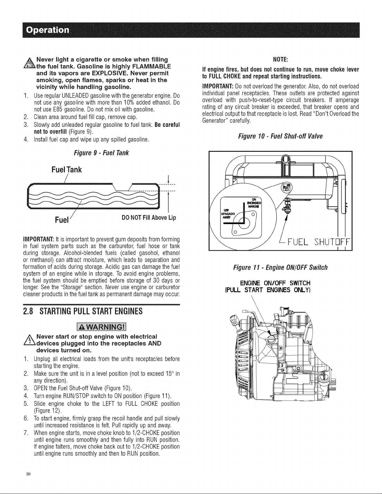
3. Slowly add unleadedregulargasolineto fuel tank. Becareful
nottooverfill (Figure9).
4. Installfuel cap andwipe up any spilledgasoline.
Figure g - Fuel Tank
FuelTank
Fuel/ Do NOTFillAboveLip
llVlPORTANT:It isimportant to preventgumdepositsfromforming
in fuel system parts such as the carburetor,fuel hose or tank
during storage. Alcohol-blended fuels (called gasohol, ethanol
or methanol)can attract moisture, which leadsto separationand
formation of acids duringstorage.Acidic gascandamagethefuel
system of an enginewhile in storage.To avoid engineproblems,
the fuel system should be emptiedbefore storageof 30 days or
longer.Seethe "Storage"section. Neveruseengineor carburetor
cleanerproductsin thefueltank aspermanentdamagemay occur.
NOTE:
If engine fires, but does not continueto run,movechokelever
to FULLCHOKEand repeatstartinginstructions.
IMPORTANT:Do not overloadthe generator.Also,do not overload
individual panel receptacles.Theseoutlets are protected against
overload with push-to-reset-type circuit breakers. If amperage
rating of any circuit breakeris exceeded,that breaker opensand
electricaloutputto that receptacleis lost.Read"Don't Overloadthe
Generator"carefully.
Figure 10 - Fuel Shut-eft Valve
Figure 11-Engine ON/OFF Switch
ENGINE ON/OFF SWITCH
(PULL START ENGINES ONLY)
2.8 STARTINGPULLSTARTENGINES
i/_X,kNever start or stop engine with electrical
devices plugged into the receptacles AND
devices turned on.
1. Unplugall electrical loadsfrom the unit's receptaclesbefore
startingthe engine.
2. Make surethe unitis in a levelposition (notto exceed15° in
anydirection).
3. OPENthe FuelShut-offValve(Figure10).
4. TurnengineRUN/STOPswitch to ONposition (Figure11).
5. Slide engine choke to the LEFT to FULL CHOKEposition
(Figure12).
6. Tostart engine,firmly graspthe recoil handleandpull slowly
until increasedresistanceisfelt. Pullrapidly up and away.
7. Whenenginestarts, move chokeknob to 1/2-CHOKEposition
until engine runs smoothly andthen fully into RUN position.
If enginefalters,move chokeback outto 1/2-CHOKEposition
untilengine runssmoothly andthento RUNposition.
1o
Page 13

Figure 12 - Choke Position
CHOKELEVER
LEFT= CHOKE(START)
RIGHT= RUN
IMPORTANT:Do not overloadthe generator.Also,do not overload
individual panel receptacles.Theseoutlets are protected against
overload with push-to-reset-type circuit breakers. If amperage
rating of any circuit breakeris exceeded,that breaker opensand
electricaloutputto that receptacleis lost.Read"Don't Overloadthe
Generator"carefully.
2.10STOPPINGTHEENGINE
1. Shut off all loads, then unplug the electrical loads from
generatorpanel receptacles.Never start or stop the engine
with electricaldevicespluggedin andturnedon.
2. Let enginerun at no-load for severalminutesto stabilizethe
internaltemperaturesof engineand generator.
3. Move Run/Stopswitchto OFFposition.
4. Closefuelvalve.
2.9 STARTINGELECTRICSTARTENGINES
Never start or stop engine with electrical
devices plugged into the receptacles AND
devices turned on.
1. Unplugall electrical loadsfrom the unit's receptaclesbefore
startingthe engine.
2. Make surethe unitis in a levelposition (notto exceed15° in
anydirection).
3. Openthefuel shut-off valve (Figures10).
4. Move engine CHOKEknoboutward to FULLCHOKEposition
(Figure12).
5. Tostart engine, press and hold the Start/Run/Stopswitch in
the"Start" position. Theenginewill crankandattemptto start.
Whenthe enginestarts, releasethe switchto the run position.
6. Whenthe engine starts, move choke knob to "1/2 Choke"
position untilthe engineruns smoothly andthenfully into the
"Run" position.If enginefalters, movechokeknobbackout to
"1/2 Choke"position untilthe engine runssmoothly andthen
to "Run" position.
2.9.1 MANUALSTART
This generatoris also equippedwith amanualrecoilstarter which
may be used if the battery is discharged.
NOTE:
The switch must be in the RUN position. Use one of the
generator's receptacleoutlets along withthe includedbattery
chargerto chargethe battery while the generator is running.
* Tostart manually,firmly grasp therecoil handleand pull slowly
until increasedresistance is felt. Pull rapidly up and away to
start engine.Thenfollow the samechoke sequence.
NOTE:
if enginefires, but does not continueto run,move chokelever
to FULLCHOKEand repeatstarting instructions.
2.11LOWOiLLEVELSHUTDOWNSYSTEM
Theengineis equippedwith a low oil levelsensorthat shuts down
theengineautomaticallywhenthe oil leveldrops belowa specified
level. If the engine shuts down by itself and the fuel tank has
enoughgasoline,checkengineoil level.
2.11.1 SENSINGLOWO/LLEVEL
If the system senses a low oil level during operation,the engine
shuts down. Theenginewill not run until the oil has beenrefilled
to theproper level.
2.12CHARGINGTHEBATTERY(ELECTRICSTART
UNITSONLY)
Storage batteries give off explosive hydrogen
gas while recharging. An explosive mixture will
remain around the battery for a long time after
it has been charged. The slightest spark can
ignite the hydrogen and cause an explosion.
Such an explosion can shatter the battery and
cause blindness or other serious injury.
_tDo not permit smoking, flame, sparks
or any other source of heat around a battery.
Wear protective goggles, rubber apron and
rubber gloves when working around a battery.
Battery electrolyte fluid is an extremely
corrosive sulfuric acid solution that can cause
severe burns, if spill occurs flush area with
clear water immediately.
Thebattery shippedwiththe generatorhasbeen fully charged.
A battery may lose some of its charge when not in use for
prolongedperiodsoftime. if the battery is unable to crankthe
engine,plugin the12V chargerincludedin the accessorybox.
RUNNINGTHEGENERATORDOESNOTCHARGETHEBATTERY.
open
NOTE:
11
Page 14
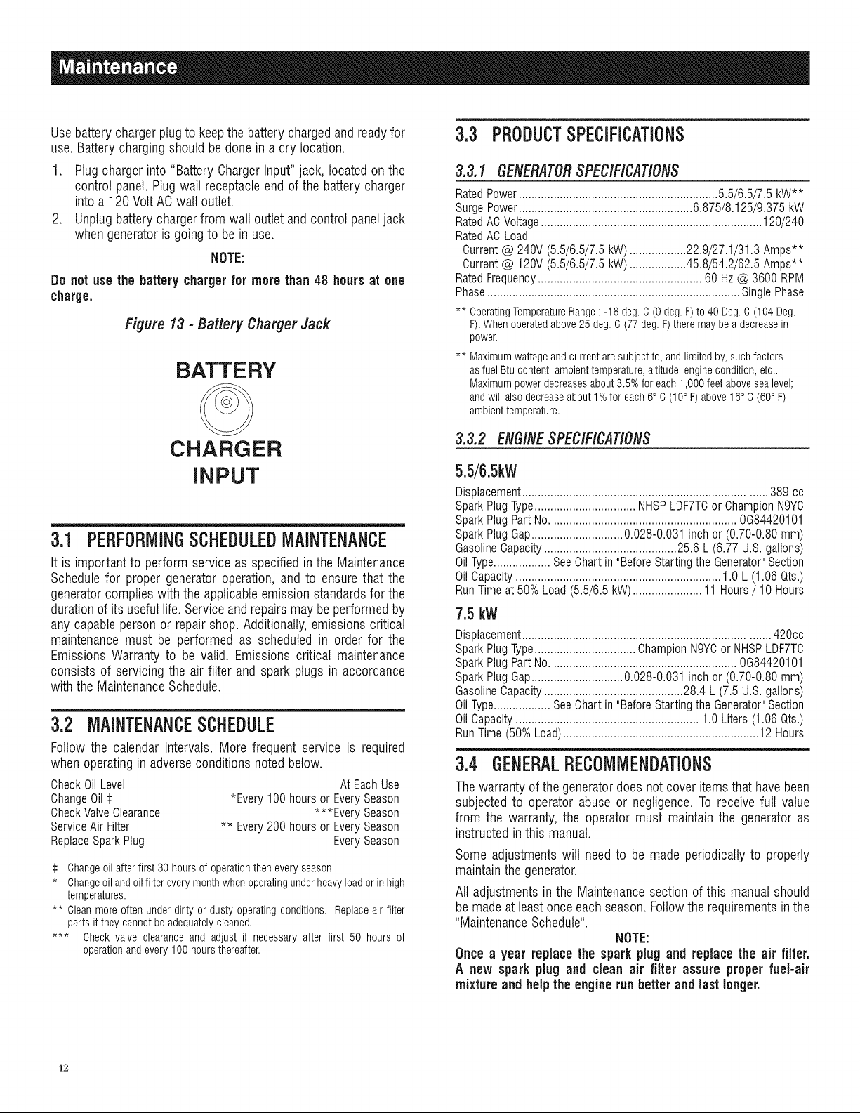
Usebatterychargerplugto keepthe batterychargedandreadyfor
use. Batterychargingshouldbe done ina dry location.
1. Plugchargerinto "Battery ChargerInput"jack, locatedon the
control panel.Plug wall receptacleendof the batterycharger
into a 120 Volt AC wall outlet.
2. Unplugbattery chargerfrom walt outletand control paneljack
whengeneratoris goingto be in use.
NOTE:
Do not use the battery chargerfor more than48 hoursat one
charge.
Figure13 - Battery Charger Jack
BATTERY
3.3 PRODUCTSPECIFICATIONS
3.3.1 GENERATORSPECIFICATIONS
RatedPower............................................................... 5.5/6.5/7.5 kW**
SurgePower....................................................... 6.875/8.125/9.375 kW
RatedACVoltage...................................................................... 120/240
RatedAC Load
Current@ 240V (5.5/6.5/7.5 kW)..................22.9/27.1/31.3 Amps**
Current@ 120V (5.5/6.5/7.5 kW)..................45.8/54.2/62.5 Amps**
RatedFrequency.................................................... 60 Hz@ 3600 RPM
Phase................................................................................ SinglePhase
** OperatingTemperatureRange: -18deg.C(0deg.F)to40Deg.C(104Deg.
F).Whenoperatedabove25deg.C(77deg.F)theremaybea decreasein
power.
** Maximumwattageandcurrentaresubjectto,andlimitedby,suchfactors
asfuelBtucontent,ambienttemperature,altitude,enginecondition,etc..
Maximumpowerdecreasesabout3.5%foreach1,000feetabovesealevel;
andwillalsodecreaseabout1%foreach6° C (10° F)above16° C(60°F)
ambienttemperature.
CHARGER
iNPUT
3.1 PERFORMINGSCHEDULEDMAINTENANCE
It is important to perform serviceas specifiedin the Maintenance
Schedulefor proper generatoroperation,and to ensure that the
generatorcomplies with the applicableemissionstandardsfor the
durationof its useful life.Serviceandrepairsmaybe performedby
any capableperson or repairshop.Additionally,emissionscritical
maintenancemust be performed as scheduled in order for the
Emissions Warrantyto be valid. Emissions critical maintenance
consists of servicing the air filter and spark plugs in accordance
with the MaintenanceSchedule.
3.2 MAINTENANCESCHEDULE
Follow the calendar intervals. More frequent service is required
whenoperatingin adverseconditions notedbelow.
CheckOilLevel AtEachUse
ChangeOil$ *Every100hoursorEverySeason
CheckValveClearance ***EverySeason
ServiceAirFilter ** Every200hoursorEverySeason
ReplaceSparkPlug EverySeason
$ Changeoil after first 30 hours of operationthenevery season.
* Changeoiland oilfilter everymonth whenoperatingunderheavy load or in high
temperatures.
** Clean more often under dirty or dusty operating conditions. Replaceair filter
parts ifthey cannot beadequatelycleaned.
*** Check valve clearance and adjust if necessary after first 50 hours of
operationand every 100 hours thereafter.
3.3.2 ENGINESPECIFICATIONS
5.5/6.5kW
Displacement.............................................................................. 389 cc
SparkPlugType................................ NHSPLDF7TCor ChampionN9YC
SparkPlug Part No........................................................... 0G84420101
SparkPlug Gap............................. 0.028-0.031 inch or (0.70-0.80 mm)
GasolineCapacity.......................................... 25.6 L (6.77 U.S. gallons)
OilType.................. SeeChart in "Before Startingthe Generator"Section
OilCapacity................................................................. 1.0 L (1.06 Qts.)
RunTimeat 50% Load (5.5/6.5 kW)...................... 11 Hours/ 10 Hours
7.5kW
Displacement............................................................................... 420cc
SparkPlugType................................ ChampionN9YCorNHSPLDF7TC
SparkPlug Part No........................................................... 0G84420101
SparkPlug Gap............................. 0.028-0.031 inch or (0.70-0.80 mm)
GasolineCapacity............................................28.4 L (7.5 U.S.gallons)
OilType.................. SeeChart in "Before Startingthe Generator"Section
OilCapacity.......................................................... 1.0 Liters (1.06 Qts.)
RunTime (50%Load)..............................................................12 Hours
3.4 GENERALRECOMMENDATIONS
Thewarranty of thegeneratordoes notcover itemsthat havebeen
subjectedto operator abuse or negligence.To receivefull value
from the warranty, the operator must maintain the generatoras
instructed inthis manual.
Some adjustmentswilt need to be made periodically to properly
maintainthegenerator.
All adjustmentsin the Maintenancesectionof this manualshould
be madeat leastonce eachseason.Followthe requirementsinthe
"MaintenanceSchedule".
NOTE:
Once a year replace the spark plug and replace the air filter.
A new spark plug and clean air filter assure proper fuel-air
mixture andhelp the engine run better andlast longer.
12
Page 15
3.4.1 GENERATORMAINTENANCE
Generatormaintenanceconsistsof keepingthe unit clean and dry.
Operateandstorethe unit in a cleandry environmentwhereit will
not be exposedto excessivedust,dirt, moistureor any corrosive
vapors.Coolingair slotsin the generatormustnot becomeclogged
with snow, leaves,or anyotherforeign material.
Checkthe cleanlinessof the generatorfrequentlyand cleanwhen
dust, dirt, oil, moisture or otherforeign substancesarevisible on
its exteriorsurface.
,ACAUTION!
Usethe followinginstructionsto changetheoil after the engine
coolsdown:
1. Cleanareaaroundoil drainplug.
2. Removeoil drain plugfrom engineandoil fill plug to drainoil
completelyinto a suitablecontainer.
3. When oil has completely drained, install oil drain plug and
tightensecurely.
4. Fill engine with recommendedoil. (See "Before Starting the
Generator"for oil recommendations).
5. Wipeup anyspilled oil.
6. Disposeof used oil at a propercollectioncenter.
,_ Never insert any object or tool through the air
cooling slots, even if the engine is not running.
NOTE:
DONOTuse a gardenhoseto cleangenerator.Water canenter
the enginefuel systemandcauseproblems.In addition,ifwater
entersthegeneratorthroughcoolingair slots,somewater will
be retainedin voidsand crevicesof the rotorand statorwinding
insulation.Water and dirt buildup on the generatorinternal
windingswill eventually decrease the insulationresistanceof
thesewindings.
3.4.2 TOCLEANTHEGENERATOR
• Usea damp cloth to wipe exteriorsurfaces clean.
• A soft, bristlebrush may be usedto loosencaked on dirt, oil,
etc.
• A vacuumcleanermay be usedto pick up loosedirt anddebris.
• Low pressure air (not to exceed 25 psi) may be used to
blow away dirt. Inspectcooling air slots and openingson the
generator.Theseopeningsmustbekeptcleanandunobstructed.
3.4.3 ENG/NEMAINTENANCE
When working on the generator, always
disconnect spark plug wire from spark plug and
keep wire away from spark plug.
3.4.4 CHECKINGOILLEVEL
Seethe "BeforeStarting the Generator"sectionfor informationon
checkingthe oil level.The oil levelshouldbe checkedbefore each
use, or at least every eight hours of operation. Keepthe oil level
maintained.
3.4.5 CHANGINGTHEOIL
Changethe oil after every 100 hours. If running this unit under
dirty or dusty conditions, or inextremelyhot weather,changethe
oil more often.
ACAUTION!
,_Hot oil may cause burns. Allow engine to
cool before draining oil. Avoid prolonged
or repeated skin exposure with used oil,
Thoroughly wash exposed areas with soap.
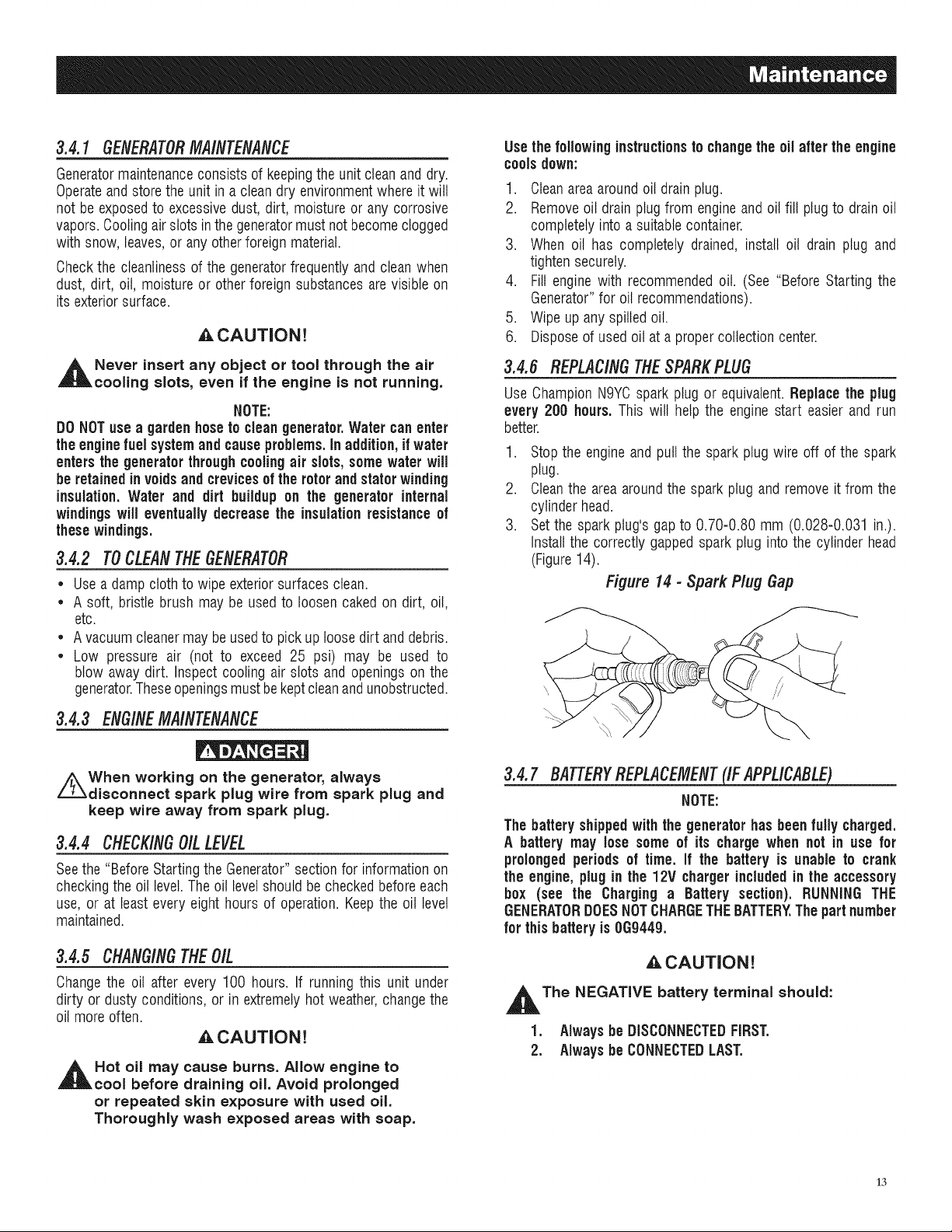
3.4.6 REPLACINGTHESPARKPLUG
Use ChampionN9YCspark plug or equivalent.Replace the plug
every 200 hours.This will help the engine start easier and run
better.
1. Stopthe engineand pull the spark plug wire off of the spark
plug.
2. Cleanthe area aroundthe spark plug and remove it from the
cylinder head.
3. Setthe spark plug'sgap to 0.70-0.80 mm (0.028-0.031 in.).
Installthe correctly gappedspark plug intothe cylinder head
(Figure14).
Figure 14 - Spark Plug Gap
3.4.7 BATTERYREPLACEMENT(IFAPPLICABLE)
NOTE:
Thebatteryshippedwiththe generator has beenfully charged.
A battery may lose some of its charge when not in use for
prolongedperiodsof time. If the battery is unable to crank
the engine,plug in the 12V chargerincludedin the accessory
box (see the Charging a Battery section). RUNNINGTHE
GENERATORDOESNOTCHARGETHEBATTERY.Thepartnumber
for this battery is 0Gg44g.
,_.CAUTION!
,_The NEGATIVE battery terminal should:
1. Always be DISCONNECTEDFIRST.
2. Alwaysbe CONNECTEDLAST.
13
Page 16
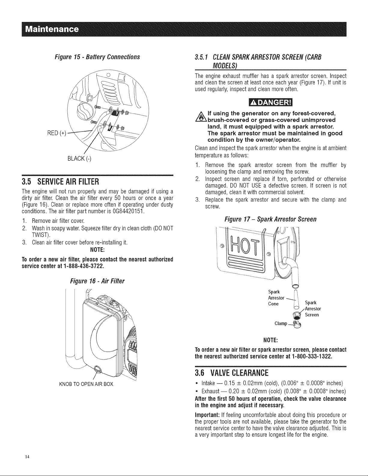
Figure 15 - Battery Connections
RED(+)
BLACK(-)
3.5 SERVICEAIRFILTER
Theenginewill not run properlyand may be damagedif using a
dirty air filter. Cleanthe air filter every 50 hours or once ayear
(Figure16). Clean or replacemore often if operating underdusty
conditions.Theair filter part numberis 0G84420151.
1. Removeairfilter cover.
2. Washinsoapywater.Squeezefilter dry incleancloth (DONOT
TWIST).
3. Cleanair filter cover before re-installingit.
NOTE:
3.5.1 CLEANSPARKARRESTORSCREEN(CARB
MODELS)_
The engineexhaustmuffler has a spark arrestor screen. Inspect
and cleanthe screenat least onceeach year (Figure17). Ifunit is
usedregularly,inspect and clean moreoften.
i/_lf using the generator on any forest=covered,
brush=covered or grass=covered unimproved
land, it must equipped with a spark arrestor.
The spark arrestor must be maintained in good
condition by the owner/operator.
Cleanandinspectthe sparkarrestorwhenthe engineisat ambient
temperatureasfollows:
1. Remove the spark arrestor screen from the muffler by
looseningthe clamp andremovingthe screw.
2. Inspect screen and replace if torn, perforated or otherwise
damaged. DONOT USEa defective screen. If screen is not
damaged,cleanit with commercialsolvent.
3. Replacethe spark arrestor and secure with the clamp and
screw.
Figure 17 - Spark Arrestor Screen
Toordera new air filter, pleasecontactthe nearestauthorized
servicecenterat 1-888-436-3722.
Figure 15- Air Filter
KNOBTOOPENAIR BOX
Spark
Arrestor "-_/
Cone i Spark
_/Arrestor
_ Screen
C,a,.p
NOTE:
Toordera newair filter or sparkarrestor screen,pleasecontact
the nearestauthorizedservice centerat 1-800-333-1322.
3.6 VALVECLEARANCE
• Intake-- 0.15 _ O.02mm(cold), (0.006" _ 0.0008" inches)
• Exhaust-- 0.20 _ O.02mm(cold) (0.008" _ 0.0008" inches)
After the first 50 hoursof operation, checkthe valve clearance
in the engine and adjust if necessary.
Important: If feeling uncomfortableaboutdoing this procedureor
theproper tools are not available,pleasetake the generatorto the
nearestservicecenterto havethevalveclearanceadjusted.This is
a very importantstepto ensurelongestlifefor theengine.
14
Page 17
3.7 GENERAL
Thegeneratorshould be started at least once every 30 days and
be allowedto run at least 30 minutes. If this cannotbe done and
the unit must be stored for more than 30 days, use thefollowing
informationas a guideto prepareitfor storage.
NEVER store engine with fuel in tank indoors
or in enclosed, poorly ventilated areas where
fumes may reach an open flame, spark or pilot
light as on a furnace, water heater, clothes dryer
or other gas appliance.
_t Allow unit to cool entirely before storage.
3.8 LONGTERMSTORAGE
It is important to preventgum depositsfrom forming in essential
fuel systemparts such asthe carburetor,fuel hose or tankduring
storage. Also, experience indicates that alcohol-blended fuels
(called gasohol,ethanolor methanol)can attract moisture,which
leadsto separationandformation of acids during storage.Acidic
gascan damagethefuel system of an enginewhile in storage.
To avoid engine problems, the fuel system should be emptied
beforestorageof 30 daysor longer,asfollows:
1. Addaqualitygasolinestabilizertothefuelperthemanufacturer's
specifications,and run the unitfor 10-15 minutes.
2. After engine cools down, remove all gasolinefrom the fuel
tank. Use a commerciallyavailable, non-conductivevacuum
siphon.
_CAUTION!
Avoid spray from spark plug hole when
cranking engine.
6. Installandtightenspark plug.Do not connectsparkplugwire.
7. Cleanthe generator outer surfaces. Check that cooling air
slots andopeningson generatorareopen and unobstructed.
8. Storethe unit in a clean, dry place.
3.9 OTHERSTORAGETiPS
* Do not store gasolinefrom oneseasonto another.
* Replacethe gasoline can if it starts to rust. Rust and/ordirt in
the gasolinewill cause problems with the carburetor and fuel
system.
* If possible,storethe unit indoors andcover it to give protection
from dust anddirt. BESURETOEMPTYTIlE FUELTANK,
* If it is not practicalto empty the fuel tank and the unit is to
be stored for some time, use a commercially availablefuel
stabilizer added to the gasoline to increase the life of the
gasoline.Runthe unit for 10-15 minutes,turn off thefuel valve
and allowto run until enginestops from lackof fuel.
* Cover the unit with a suitable protective cover that does not
retainmoisture.
_t NEVER cover the generator while engine and
exhaust areas are warm.
Drain fuel into approved container outdoors,
away from open flame. Be sure engine is cool.
Do not smoke.
3. Start and run engineuntilenginestops from lackof fuel.
4. After engine cools down, drain oil from engine. Refill with
recommendedgrade.
5. Remove spark plug and pour about 1/2 ounce (15 mt) of
engineoil intothecylinder.Coverspark plugholewith rag.Pull
the recoil starter a couple times to lubricatethe piston rings
and cylinder bore.A fogging agent can also be used in the
placeof oil.
15
Page 18

4.1TBOUBLESHOOTINGGUIDE
Engineis running,but no AC output
isavailable.
1. Circuitbreakeris open.
2. Poorconnectionor defectivecord set.
3. Connecteddeviceis bad.
4. Faultin generator.
1. Resetcircuit breaker.
2. Checkand repair.
3. Connectanotherdevicethat is in goodcondition.
4. ContactAuthorizedServiceFacility.
Engineruns well hut bogs down 1. Short circuit in a connectedload. 1. Disconnectshorted electrical load.
whenloadsare connected. 2. Generatoris overloaded. 2. See"Don't Overloadthe Generator".
3. Enginespeedis too slow. 3. ContactAuthorizedServiceFacility.
4. Shorted generatorcircuit. 4. ContactAuthorizedServiceFacility.
I I
Enginewill notstart;orstartsand
runsrough.
1. FuelShut-off is OFF.
2. Dirty airfilter.
3. Outof gasoline.
4. Stalegasoline.
5. Sparkplug wire not connectedto spark plug.
6. Bad sparkplug.
7. Waterin gasoline.
8. Overchoking.
9. Low oil level.
10. Excessiverichfuel mixture.
11. Intakevalve stuck openor closed.
12. Enginehas lostcompression.
= I
1. TurnFuelShut-off ON.
2. Cleanor replaceairfilter.
3. Fillfuel tank.
4. Drainfuel tank andfill with fresh fuel.
5. Connectwire to sparkplug.
6. Replacespark plug.
7. Drainfuel tank; fill with fresh fuel.
8. Putchoke knob to NoChokeposition.
9. Fillcrankcaseto properlevel.
10. Contact AuthorizedServiceFacility.
11. Contact AuthorizedServiceFacility.
12. Contact AuthorizedServiceFacility.
Engineshuts downduring 1. Outof gasoline. 1. Fillfuel tank.
operation. 2. Low oil level. 2. Fillcrankcaseto properlevel.
3. Faultin engine. 3. ContactAuthorizedServiceFacility.
m R
Enginelacks power. 1. Loadis too high. 1. Reduceload (see"Don't Overloadthe Generator").
2. Dirty airfilter. 2. Cleanor replaceairfilter.
3. Engineneedsto be serviced. 3. ContactAuthorizedService Facility.
= I
Engine"hunts" or falters. 1. Chokeis openedtoo soon. 1. Movechoketo halfway positionuntil engineruns
smoothly.
2. Carburetoris running too rich or too lean. 2. ContactAuthorizedServiceFacility.
16
Page 19

17
Page 20

Manual PartNo. 0K0172 Rev.F(12/13/13) Printedin China
Page 21

G ®
• • _ • ®
anual propietari
eneradorportatiJSerie
GARANTiA
LIMI A D
19
Page 22

Introduccion..........................................................21
Mantenimiento ...................................................... 32
Leaestemanualminuciosamente........................21
Reglasdeseguridad.............................................21
[ndicedenormas ............................................................................... 23
Informationgeneral..............................................24
1.1 Desembalaje.......................................................................... 24
1.2 Armado.................................................................................. 24
1.3 Informacionsobre emisiones................................................. 25
Funcionamiento....................................................25
2.1 Conozcaelgenerador............................................................ 25
2.2 Horometro............................................................................. 26
2.3 Enchufesdeconexion............................................................ 26
2.4 Come usar el generador......................................................... 27
2.5 No sobrecargueel generador.................................................28
2.6 Guiadereferenciade potencia enwatts................................. 29
2.7 Antes dearrancarel generador.............................................. 29
2.8 Arranquede motores con arranquecon tirador.......................30
2.9 Arranquede motores con arranqueelectrico..........................31
2.10 Paradadelmotor ................................................................... 31
2.11 Sistemadeapagadoper nivelde aceitebajo..........................31
2.12 Oargade la bateria (unidadescon arranque
electricosolamente)...............................................................32
3.1 Realizacbn delmantenimientoprogramado............................32
3.2 Programade mantenimiento................................................... 32
3.3 Especificacionesdel producto................................................ 32
3.4 Recomendacionesgenerales..................................................33
3.5 Servicio delfiltro deaire......................................................... 34
3.6 Holguradevalvulas................................................................ 35
3.7 Generalidades........................................................................ 35
3.8 Almacenamientoa largoplazo................................................ 35
3.9 Otrosconsejos sobre el almacenamiento...............................35
Resolucionde problemas.....................................36
4.1 Guiade resolucionde problemas...........................................36
Netas .................................................................... 37
ADVERTENCIA!
Proposicion 65 de California
Elescape del motory algunosde sus componentesson conocidospore elEstadode Californiacome
causa de cancer,defectos congenitosy otrosdaSosreproductivos.
ADVERTENCIA!
Proposicion 65de California
Este productocontiene o emite sustanciasquimicas que son conocidas per el Estadode California come
causa de cancer,defectos congenitosy otrosdaSosreproductivos.
20
Page 23

INTBODUCCiON
r
Muchas gracias per haber comprado este modelo de Generac Power
Systems, Inc. Este modelo es un generador impulsado per motor,
compacto, de alto rendimiento y enfriado per aire disefiado para
suministrar alimentacionelectricapara utilizarcargaselectricasdonde no
haya alimentacionde servicio publico disponible o come reemplazode
dicha alimentaciondebidoa un apagon.
LEAESTEMANUALMINUCIOSAMENTE
Si una parte de este manual no se comprende, comuniquese con el
concesionarioautorizadomas cercanopara conocer los procedimientos
de arranque,operaciony mantenimiento.
El operador es responsable del use correcto y seguro del equipo.
Recomendamosfirmementeque eloperadorleaestemanualy comprenda
completamentetodas las instruccionesantesde usar el equipo.Tambien
recomendamos firmemente instruir a otras personas en el arranque y
la operacion correctos de la unidad.Esto las preparaen el case de que
deban operar el equipo en una emergencia.Guarde estas instrucciones
para referencia en el future. Si presta este dispositivo a otra persona,
SlEMPREentregueletambien esta instrucciones.
El generadorpuede funcionar de manerasegura, eficiente y fiable solo
si es ubicado,operado y mantenidocorrectamente.Antes de operar el
generadoro darle servicio:
• Familiaricesecontodos los codigos y reglamentoslocales, estatalesy
nacionales,y cumplalosde maneraestricta.
• Estudietodas las advertenciasdeseguridadindicadasen estemanual
y en el producto minuciosamente.
• Familiaricesecon este manualy la unidadantes del use.
El fabricante no puede prever todas las circunstancias posibles que
podrian involucrar un peligro. Las advertenciasde este manual y los
rotulos y etiquetasadhesivasfijados en la unidad,per Io tanto, no son
exhaustivos. Si usa un procedimiento, metodo de trabajo o tecnica
de funcionamiento que el fabricante no recomienda especificamente,
aseguresede que sea seguropara otras personas.Aseguresetambien
de que el procedimiento,metodo detrabajo o tecnica defuncionamiento
utilizadonovuelvaninseguro al generador.
LA INFORMACIONQUE FIGURA EN EL PRESENTESE BAS0 EN
MAQUINASQUE ESTABANEN PRODUCCIONAL MEMENTO DE LA
PUBLICACl0N.GENERACSE RESERVAEL DERECHODE MODtFICAR
ESTEMANUALENCUALQUIERMEMENTO.
BEGLASDESEGURIDAD
Entodaestapublicaci6n,enlos r6tulosyen las etiquetasadhesivasfijadas
en el generador,los bloquesde PELIGRO,ADVERTENCIA,PRECAUCION
y NOTAse usan para alertar al personalsobre instrucciones especiales
acerca de una operacion en particular que puede ser peligrosa si se
efectuade maneraincorrectao imprudente.Observeloscuidadosamente.
Sus definicionesson lassiguientes:
INDICAUNA SITUACI6N0 ACCIONPELIGROSAQUE,SI NOSE EVITA,
OCASIONARALA iVlUERTE0 LESIONESGRAVES.
Indica unasituacion e accion peligrosaque, si no se
evita, podriaocasionarla rnuerteo lesiones graves.
CUIDADO
Indica unasituacion o accion peligrosaque, si no se
evita, podriaocasionarlesionesleves o rnoderadas.
NOTA:
Las notas contienen informacion adicional importante para un
procedimiento y se encuentran dentro del texto del cuerpo de este
manual.
Estas advertencias de seguridad no pueden eliminar los peligros que
indican. Elsentidocomun y elcumplimiento estrictode lasinstrucciones
especialesmientras se desarrollala accion o el servicio son esenciales
para la prevenciondeaccidentes.
Cuatrosimbolosdeseguridaddeusecomun acompafianalos bloquesde
PELIGRO,ADVERTENCIAy PRECAUCION.Cada un0 indica el siguiente
tip0 de inf0rmaci0n:
_i ste sfmbolo sehala informaci6n de seguridad
importante que, si no se respeta, podrfa porter
en peligro la seguridad personal y/o material de
terceros.
Este sfmbolo sehaia un posible peligro de expiosi6n.
//_Este sfmbolo sehaia un posible peligro de incendio.
Este sfmbolo sehala un posible peligro de choque
el_ctrico.
21
Page 24

PELIGROSGENERALES
• NUNCAoperela unidaden una zona confinada, en un vehiculoo en
interiores,AUNSIlas puertas y ventanasestanabiertas.
• Per motives de seguridad, el fabricante recomienda que el
mantenimientode este equipo sea efectuado per un concesionario
autorizado. Inspeccione el generador regularmente,y pongase en
contacto conel concesionarioautorizadomascercano enrelaci6ncon
las piezasquenecesitanreparaciono sustitucion.
• Utilice el generador solamente sobre superficies niveladas y donde
no este expuestoa humedad, suciedad, polvo o vapores corrosives
excesivos.
• Mantenga las manes, pies, ropa, etc. alejados de las correas de
transmision y otras piezas en movimiento. Nunca retire ningun
protectoro escudo de ventilador mientrasla unidadestefuncionando.
• AIgunas piezas del generador se calientan en extreme durante el
funcionamiento.Mantengasealejado de] generadorhastaque se haya
enfriadoparaevitarquemadurasgraves.
• NOuse elgeneradordebajode la Nuvia.
• No modifiquelaconstruccion del generadoro cambielos controles,ya
quepodriangenerasecondiciones defuncionamiento inseguro.
• Nunca arranqueo pare la unidadcon cargas electricas conectadasa
tomacorrientesY condispositivosconectadosencendidos.Arranqueel
motory permitaque se estabiNceantes de conectar cargaselectricas.
Desconectetodas las cargas electricasantesde apagarel generador.
• No inserteobjetosa travesdelas ranurasdeenfriamientodela unidad.
• Cuandotrabaje en este equipo,mantengasealerta en todo memento.
Nuncatrabajeen el equipocuando estefatigadofisica o mentalmente.
• Nunca useel generadoro cualquierade sus piezascome un escal6n.
Pararse sobre la unidad puede forzar y romper piezas y podria
ocasionar condiciones de funcionamiento peligrosas per fugas de
gasesdeescape,fugas decombustible,fugas de aceite, etc.
NOTA:
Estegenerador puede estar equipado con un silenciador supresor de
chispas. El supresor de chispas debe ser mantenido en condiciones
de trabajo eficaces per el propietario/operador. En el Estado de
California, se requiere per ley un supresor de chispas (Seccibn 4442
del California PublicResources Code[Codigo de recursos p[/blicos de
California]). Otros estados pueden tener leyes similares. Se aplican
leyes federales en las tierras federales.
PELiGROSRELACIONADOSCONELESCAPE
Y LAUBICACION
• iNnunca use la unidad en una zona cenfinada e en interiores!
iNUNCA use la unidad en el begat, en un vehiculo e en zenas
parciaimenteconfinadastales comegarajes, AUN SI las puertasy
ventanasest;in abiertas!UseSOLAMENTEen exteri0res y lejos de
ventanas,puertasy ventilacionesabiertas, y en unazonaderideno
se acumulen vaporesde escape mortales.
Usar un generador en interiores LO PUEDE
MATAR EN MINUTOS,
Los gases de escape del generador contienen monoxide
de carbono. Este es un veneno que no se puede vet u oler.
NUNCA Io use dentro de una
casa o garaje,AUN SI la puerta
y las ventanas se encuentran
abiertas.
• Los vapores de escape del motor contienenmonoxido de carbono,
que no se puede ver ni oler. Estegas venenoso, si se respira en
concentraciones suficientes, puede causar perdida de conocimiento
o incluso la muerte.
• El flujo adecuado y sin obstrucciones del aire de enfriamiento y
ventilaci6n resulta critico para el funcionamiento adecuado del
generador.No altere la instalacion ni permita el bloqueo, ni siquiera
parcial, del suministro de ventilacion, dado que esto puede afectar
seriamenteel funcionamiento seguro del generador.El generadorSE
DEBEusar enexteriores.
• Estesistema de escapedebe sermantenido adecuadamente.Nohaga
nada que pueda volver inseguro al sistema de escape o que infrinja
cualquiercodigo y/o norma local.
• Siempre use en interiores una alarma de monoxido de carbono
alimentada por bateria instalada conforme alas instrucciones del
fabricante.
• Si comienza a sentirse enfermo, mareado o debil despues de que el
generador ha estado funcionando, salga INMEDIATAMENTEal aire
fresco. Oonsultea un medico, ya que podria sufrir envenenamiento
por monoxidodecarbono.
Use unicamente en
EXTERIORES, y alejado de
ventanas, puertas
y ventilaciones.
22
Page 25

PELIGROELI CTRICO
• Elgeneradorproduce un voltaje peligrosamentealto cuando esta en
funcionamiento.Eviteelcontacto con cables,terminales, conexiones,
etc.desnudosmientraslaunidadestafuncionando,aun en los equipos
conectados al generador. Asegurese de que todas las cubiertas,
proteccionesy barrerasadecuadas esten colocadas antes de utilizar
el generador.
• Nunca maneje ningun tipo de cable o dispositivo electrico mientras
este parado sobre agua o este descalzoo cuando tenga las manos
o los pies mojados. PUEDEPRODUCIRSEUN CHOQUEELF:CTRICO
PELIGROSO.
• El Codigo Electrico Nacional de los EE. UU. (NEC) requiere que
el bastidor y las piezas conductoras de electricidad externas del
generadoresten correctamente conectadas a una conexion a tierra
aprobada. Los codigos de electricidad locales tambien pueden
requerirla conexiona tierra apropiadadelgenerador.Consultecon un
electricistalocal los requisites deconexion atierra desu zona.
• Useun interrupter decircuito per fallo deconexionatierra entodaslas
zonashumedaso altamenteconductoras (talescome zonasdetrabajo
con tarimas metalicas o estructurasde acero).
• No use el generador con juegos de cables electricos de conexion
gastados,desnudos, deshilachados o que tengan algun otro tipo de
da5o.
• Antesdeefectuarcualquiermantenimientoen elgenerador,desconecte
la bateria de arranquedel motor (de tenerla) para evitarun arranque
accidental. Desconecteprimero el cable del borne de bateriaindicado
perNEGATIVO,NEGo (-). Vuelvaa conectarese cableenultimo lugar.
• En case de accidente causado per cheque electrico, apague de
inmediatola fuente de alimentacionelectrica. Si esto no es posible,
intente liberar a la victima del conductor alimentado. EVITE EL
CONTACTODIRECTOCON LA V[CTIIVlA.Use un implemento no
conductor, como una cuerda o tabla, para liberar a la victima
del conductor alimentado. Si la victima esta inconsciente, aplique
primeros auxiliosy obtengaayudamedicade inmediato.
PELIGRODEINCENDIO
* La gasoiina es aitamente INFLAMABLE y sus vapores son
EXPLOSIVOS.Nunca permita que se fume e que haya llamas
abiertas, chispasocaler en la zona mientras maneje gasolina.
, Nunca agregue combustible mientras la unidad esta funcionando o
caNente.Espere a que el motor se enfrie completamenteantes de
agregarcombustible.
* Nunca llene el tanque de combustibleen interiores. Cumpla todas
las leyesque reglamentanel almacenamientoy manejode gasolina.
, No Ilene el tanque de combustible en excese. Siempre deje
lugar para la expansi6ndel combustible.Si se Nenael tanque en
exceso, el combustible puede rebasar sobre un motor caliente y
causar INCENDIOo EXPLOSION.Nunca almacene el generador con
combustible en el tanque deride los vapores de la gasolina podrian
alcanzar una llama abierta, chispa o luz piloto (come de un homo,
calderaosecador deropa). PuedeocasionarINCENDtOo EXPLOSION.
Permitaque la unidadse enfriecompletamente antesde almacenarla.
, Recoja y seque inmediatamentetodos los derramesde combustible
o aceite.Aseguresede queno quedenmaterialescombustibles en el
generadoro cerca de este.Mantenga la zona alrededordel generador
limpia y sin residues, y deje un espaciolibre de 4.6 m (5 ft) enredes
los costados a fin depermitir la ventilacionapropiadadelgenerador.
• No inserteobjetosa travesdelas ranurasdeenfriamientodela unidad.
• Nunca use el generador si los dispositivos electricos conectados se
recalientan,si se pierde la salidaelectrica, si el motor o el generador
producenchispaso si se observanllamas o humo mientrasla unidad
estafuncionando.
• Mantenga un extintor de incendio cerca del generador en todo
momento.
INO/CEDENORMAS
1. National Fire Protection Association (Asociacion nacional de
proteccion contra incendios [NFPA])de los EE.UU. 70: NATIONAL
ELECTRICCODE(Codigo electrico nacional de los EE. UU., NEC)
disponibleen www.nfpa.org
2. National Fire Protection Association (Asociacion nacional de
proteccioncontra incendios [NFPA])delos EE.UU.5000: BUILDING
CONSTRUCTIONAND SAFETYCODE (Codigo de construccion y
seguridadde edificios) disponible enwww.nfpa.org
3. International BuildingCode (Codigo de construccion internacional)
disponibleen www.iccsafe.org
4. Agricultural Wiring Handbook (Manual de cableado agricola)
disponible en www.rerc.org, RuralElectricity Resource Council RO.
Box309 Wilmington,OH45177-0309, EE.UU.
5. ASAE EP-364.2 Installation and Maintenance of Farm Standby
ElectricPower(lnstalaci6nymantenimientodealimentaci6nelectrica
rural de reserva) disponible en www.asabe.org,American Society
of Agricultural & Biological Engineers (Sociedad estadounidense
de ingenieros agricolasy biologicos) 2950 Niles Road, St. Joseph,
MI 49085, EE.UU.
Esta lista no es exhaustiva. Compruebe con la autoridad que tiene
jurisdiccion local (AHJ, per sus siglas en ingles) todos los codigos o
normas quepodrian corresponderasu jurisdiccion.
NUM. DE
MODELO:
NOM. DE
SERIE:
Ubicacion de la IO de la unidad
UETA
DEDATOS
DELMODELO
23
Page 26

1.1 DESElVlBALAJE
• Retiretodo elmaterialdeembalaje.
• Retirela caja de accesoriosseparada.
• Retireel generadorde la caja.
1.1.1 ACCESORIOS
Revisetodo el contenido.Si falta algunapiezao hayalgunapiezadahada,
comuniquesecon unconcesionario autorizadoal1-888-436-3722.
• 1 - Manualdelpropietario
• 1 - Litro de aceiteSAE30
• 2 - RuedasNever-Flat
• 3 - Tarjetasde registrodel producto
• 1 - ServiceWarranty
• 1 - Cargadorde baterias (modeloscon arranqueelectrico)
• 1 - Bolsadetornilleria (contieneIo siguiente):
- 2-Pies de caucho 6-PernosM8 (largos)
- 2-Pasadoresdeeje de 1/2 in 2-PernosM6 (largos)
- 2-Pasadoreshendidos 2-Tuercasciegas M8
- 2-Arandelasplanas de1/2 in 4-Tuercashexagonales
- 2-TuercashexagonalesembridadasM6
1 - Conjuntode manija
2 - Piedel bastidor
1 - Cablede alimentacion
de 6 m (20 ft)
(006110-3 solamente)
1 - EmissionsWarranty
embridadasM8
1.2 ARIVIADO
Elgeneradorrequierearmadoantesdel uso. Si surgenproblemas durante
el armado del generador,Namea la Linea de ayudapara generadoresal
1-888-436-3722.
1.2.1 ARMADODELKITDEACCESORIOS
Las ruedas de launidad se han disehadopara aumentaren gran medida
la facilidad detransporte delgenerador.
Necesitaralas siguientesherramientaspara instalar el kit de accesorios
de maneraapropiada.
• Pinzasde puntade aguja
• Trinquetey casquillos de8 mm, 10 mm y 13 mm
• Llavesde boca de 8 mm, 10 mmy 13 mm
NOTA:
Lasruedas no est;in destinadas al usoeo caminos.
1. Consultela Figura1 einstale lasruedasdel siguientemodo:
- Desliceel pasadordeeje atravesde la rueda,laarandelaplanade
1/2 in y el soporte de la rueda sobre el bastidor.
- Inserte el pasador hendido a traves del pasador de eje y luego
done las lengiJetas (del pasador hendido) hacia afuera para
trabarlo en su posicion.
2. Consultela FiguraI einstaleel pie delbastidory los parachoquesde
caucho come se muestra.
- Deslicelos esparragosdelos parachoquesdecauchoa travesdel
piedel bastidor einstale las contratuercasembridadas.
- Deslice los pernosde cabezahexagonala traves de los agujeros
enel riel del bastidor.
- Desliceel piedel bastidor sobre los pemos de cabezahexagonaly
luegoinstale las contratuercasembridadas.
3. Consultela Figura1 einstale lamanijacome se muestra.
- Deslice los pernos largos a traves del soporte de la manija y la
manijay luegoinstale las tuercas hexagonales.
Figura 1 - Armado de las ruedas y la manija
4 XPERNOSM8 (LARGO)
2 X PiE DEL BASTiDOR
24 X TUERCAS M8
2 X PIE DE CAUCHO _=[1_'_%
2x TUERCAS M6
"_ 2 X PERNO M6 (LARGO)
1.2.2 CONEXiONDELOSCABLESDELABATERIA
__(ARRANQUE ELECTRiCOSOLAMEflTE
La unidad se entrega deliberadamente con los cables de la bateria
desconectados.
Para conectar la bateria, necesitara,dos Ilaves de boca de 8 mm para
conectar los cables de labateria. (vea los detalles de la conexion en la
Figura16):
1. Corte las bandasde amarre de cables que sujetanlos cablesde la
bateriay retirelas cubiertasrojasde los bornes dela bateria.
2. Primero,conecteel cable rojo al borne positivo (+) dela bateriacon
el pernoy latuerca provistos.
3. Aseguresedequelas conexionesestenbienfijadasy deslicelafunda
decauchorojo sobreel borne positivo (+) de labateriay latornilleria
de conexion.
4. Oonecteelcable negroal bornenegativo(-) de labateriacon elperno
y la tuerca provistos y deslice la funda de caucho sobre el borne
negativo (-) de la bateriay la tornilleria de conexi6n.
5. Aseguresede quetodaslas conexionesbienfijadas.
NOTA:
Si la bateria no puedearraocar el motor, carguelacoo el cargaderde
12 V incluideen la caja de accesorios (yea los detalles ea la secci6o
"Carga de la bateria").
24
Page 27

1.3 INFOBMACiONSOBBEEMISIONES
La Agenciade ProteccionAmbiental de los EE.UU. (EPA)(y la Junta de
RecursosdelAire de California[CARB]para los generadorescertificados
conforme alas normas de California) requieren que este generador
cumpla las normas de emisiones de escape y evaporaci6n. Localice
la etiqueta adhesiva sobre cumplimiento de Ins normas referidas a
emisionescolocadasobre elmotor paradeterminarquenormas satisface
el generador,yparadeterminarque garantiacorresponde.Estegenerador
cuenta con certificaci6n para funcionar con gasolina. El sistema de
control de emisionesincluye los siguientescomponentes(de tenerlos):
• Sistemade induccbn de aire
- Tubo/colectorde admision
- Filtrode aire
• Sistemade combustible
- Carburador
- Tanque/tapadecombustible
- Tuberiasde combustible
- Tuberiasdeventilaci6n deevaporacion
- Cartucho de carbon
• Sistemade encendido
- Bujia
- Modulo de encendido
• Sistemade escape
- Colectorde escape
- Silenciador
- Valvula deaire per impulses
- Catalizador
11. Manija - Pivoteay se retrae para el almacenamiento. Oprima el
boton cargadoa resortepara mover las manijas.
12. Tapade gasolina- Ubicacbn paraIlenadodecombustible.
13. Medidor de combustible - Muestra el nivel de combustible del
tanque.
14. Llenado de aceite - Agregueaceiteaqui.
15. Arrancaderconcuerda- Seusaparaarrancarelmotor manualmente.
16. Cierrede combustible -VD.Ivula entreeltanquede combustibley el
carburador.
17. V_ilvulade inversiou - Permiteel paso decombustiblea la cD.mara
de airedel motor.
18. Manguera de recuperation - Seinstalaentreel cartucho decarbon
y lavalvula deinversion (de tenerla).
19. Horometro- Llevaun registro de lashorasde funcionamiento.
20. Entrada del cargader de bateria - Este tomacorriente permite
recargar la bateriapara almacenamientode 12 VCC provista con
el cargador con adaptador de 12 V que se incluye en la caja de
accesorios. Detras de la entrada del cargador de bateria hay un
fusible en linea de 1.50 A, que se encuentradentro del tablero de
control para proteger la bateria (modelos con arranque electrico
solamente).
21. Bateria - Alimenta al arrancador electrico (modelos con arranque
electricosolamente).
22. Supresor de chispas- Reduceelpeligro de incendiosconteniendo
las chispas (modelosCARBsolamente).
Figura2A - Tablemdecontrol
(modelospara 49 estados)
2.1 CONOZCAELGENEBADOB
Lea el IVlanual del propietarioy ins Begins de seguridad antes de
operareste generador.
Compareel generadorcon las Figuras2 a 4 para familiarizarsecon las
ubicacionesde los diversoscontroles y ajustes.Guardeestemanualpara
referenciaen elfuture.
1. Tomacerriente deble de 120 VCA,20 A- Suministra alimentacbn
electricaparael funcionamiento deiluminaci6n electrica,artefactos,
herramientasy cargas de motor de 120 VCA, 20 A, monofasicos,
de 60 Hz (los modelos CARB cuentan con tomacorrientes con
interrupterper fallo de conexbn atierra [GFOl]).
2. Temacerrientede 120/240 VCA, 30 A con bloquee - Suministra
alimentacbn electrica para el funcionamiento de iluminacion
electrica, artefactos, herramientas y cargas de motor de 120 y/o
240VCA, 30 A, monofasicos, de60 Hz.
3. Disyuntores (CA) - Cada tomacorriente cuenta con un disyuntor
de oprimir para reconectar para proteger al generador contra
sobrecargaselectricas.
4. Vaciadode aceite - Seusa paravaciarel aceite delmotor.
5. Filtre de aire - Filtraelaire de admisbn a medidaque ingresa enel
motor.
6. Perilla del cebador- Seusa paraarrancarun motor frio.
7. Tanque de combustible- Vea la capacidad del tanque en las
especificacionesdel generador.
8. Terminal de conexiona tierra - Conecteaqui el generadora una
conexbn a tierra aprobada.Vealos detallesen"Conexiona tierra del
generador".
g. interrupterRun/Step(Marcha/Parada)- Controlaelfuncionamiento
delgenerador (modeloscon arranquecontirador).
gA. interrupterStart (Arranque) - Se usapara arrancarel motor desde
el arrancador(modelos con arranqueelectrico solamente).
10. Silenciador - Reduceelruido del motor.
Figura 2B - Tablem de centre/(modelos CARB)
Page 28

Figura 2C - Tab/ero de contro/ (mode/os CSA)
Figura 3 - Controles delgenerador
2.2 HOBOMETBO
El horometro Ileva un registro de las horas de funcionamiento parael
mantenimientoprogramado(Figura5):
Se visualizaraun mensaje "CHG OIL" (Oambiaraceite)cada 100 horas.
El mensajedestellara1 hora antesy una1 despuesde cada intervalode
100horas,proporcionandounaventanade2horasparaefectuarelservicio.
Este mensaje realmente comenzara a destellar alas 99 horas y
se desactivara en forma automatica alas 101 horas nuevamente,
proporcionandouna ventanade 2 horas paraefectuarel servicio.
Oada200 horas destellarael icono "SVO"(Servicio)en el anguloinferior
izquierdo de la pantalla. El mensaje destellara 1 hora antes y una
1 despues de cada intervalo de 200 horas, proporcionandouna ventana
de 2 horaspara efectuarel servicio.
Figura 5 - Horometro
f
0000.0
f
Figura 4 - Controles del generador
GRAFICO BOTONDE
DE RELOJ RESTABLECIIVllENTO
DEARENA (DE TENERLO)
Ouandoel horometroesta en el modo de alerta destellando, el mensaje
de mantenimiento siempre mostrara el tiempo transcurrido en horas y
decimos. Lashoras destellarancuatroveces, y luego sealternarancon el
mensaje de mantenimientocuatro veces hasta que el medidor se ponga
en cero automaticamente.
• 100 horas-OHGOIL-- Intervalodecambio deaceite(cada100 horas)
• 200 horas- SVC-- Servicio del filtro de aire (cada 200 horas)
Nota:
El gr_ifico de reloj de arena destellar_iintermitentementecuando el
motor estafuncionando. Estosignificaque el medidor esta Ilevaodo un
registro delas horasde funciooamiento.
2.3 ENCHUFESDECONEXION
2.3.1 TOMACORRIENTEBOBLEBE 120 VCA,20A
Es un tomacorriente de 120 V protegido contra sobrecargas por un
disyuntor de oprimir para reconectar de 20 A (Figura 6). Use cada
toma para proporcionar alimentaci6n a cargas electricas de 120 VCA,
monofasicas, de 60 Hz, que requieren una corriente combinada de
2400 W (2.4 kW) o 20A como maximo. Usesolamentejuegosde cables
conexion de 3 conductores con conexi6n a tierra, de alta calidady bien
aislados,con una capacidadnominalde 125 V con 20 A (o mayor).
Use cables de extension Io mas cortos posible, preferentemente de
menosde 4.6 m (15 ft) delargo, paraevitar caidasde voltajey elposible
recalentamientodelos alambres.
26
Page 29

Figura 6 - Tomacorriente doble de 120 VCA, 20 A
2.3.2 TOMACORRIENTEOOBLECON/NTERRUPTORPOR
FALLODECONEZiONA TIERRA(GFCl)DE 120 I/CA,
20 A_(CARBSOLAMENTE)
Es un tomacorriente de 120 V protegido contra sobrecargas por un
disyuntor de oprimir para reconectar de 20 A (Figura 6A). Use cada
toma para proporcionar alimentaci6n a cargas electricas de 120 VCA,
monofasicas, de 60 Hz, que requieren una corriente combinada de
2400 W (2.4 kW) o 20 Acomo maximo. Usesolamentejuegosde cables
conexi6n de 3 conductores con conexi6n a tierra, de alta calidad y bien
aislados,con una capacidadnominalde 125 V con 20 A (o mayor).
Use cables de extension Io mas cortos posible para evitar caidas de
voltajey el posible recalentamientodelos alambres.
Figura 6A - Tomacorriente doble con interruptor por
ratio de conexion a tierra (GFCl) de 120 VCA, 20 A
2.3.3 TOMACORRIENTEDE120/240 VC&30 A
UseunenchufeNEMAL14-30 conestetomacorriente(gireparabloquear/
desbloquear).Conecteunjuego decables de conexionde4 conductores
con conexiona tierra adecuadopara el enchufe y la carga deseados.El
juego decables deconexiondebetener capacidadnominalpara 250 VCA
con 30 A (o mayor) (Figura7).
Use este tomacorriente para usar cargas de 120 VOA, monofasicas, de
60 Hz que requieren hasta 3600 W (3.6 kW) de potencia con 30 A o
cargasde 240 VCA, monofasicas,de 60 Hzquerequierenhasta7200 W
(7.2 kW) de potencia con 30 A. El tomacorriente esta protegido por
dos interruptores de oprimir para reconectar de 25 A (5.5 kW) o dos
interruptoresdelmismo tipo de 30 A (6.5 kW) o uninterruptor basculante
de2 polos de30 A o dosdisyuntoresdeboron deoprimir parareconectar
de 30 A (6.5/7.5 kW).
Figura 7 - Tomacorriente de 120/240 VCA, 30 A
12OV/24OV
3OA
2.4 C6MOUSARELGENERADOR
Oonsultela seccion"Arranquedel motor" paraver como arrancary parar
el generadorde manera segura y como conectar y desconectarcargas.
Si surgen problemasduranteelfuncionamiento del generador,Namea la
Lineadeayuda para generadoresal 1-888-436-3722.
,_iNunca use la unidad en una zona confinada o en
interiores! iNUNCA use la unidad en el hogar, en un
vehfculo o en zonas parcialmente confinadas tales
como garajes, AUN SI las puertas y ventanas est_n
abiertas!Use SOLAMENTE en exteriores y lejos de
ventanas, puertas y ventilaciones abiertas, yen una
zona donde no se acumulen vapores de escape
mortales.
,_Los vapores escape motor
mon6xido de carbono, que no se puede vet ni oler.
Este gas venenoso, si se respira en concentraciones
suficientes, puede causar p_rdida de conocimiento
o incluso la muerte.
,_EI adecuado sin obstrucciones del aire de
,_ Este sistema de debe mantenido
,_1 Siempre interiores alarma de monSxido
flujo
enfriamiento y ventilaci6n resulta crftico para el
funcionamiento adecuado del generador. No altere
la instalaci6n ni permita el bloqueo, ni siquiera
parcial, del suministro de ventilaci6n, dado que
esto puede afectar seriamente el funcionamiento
seguro del generador. El generador SE DEBE usar
en exteriores.
adecuadamente. No haga nada que pueda volver
inseguro al sistema de escape o que infrinja
cualquier cSdigo y/o norma local.
de carbono alimentada pot baterfa, instalada
conforme alas instrucciones del fabricante.
de del contienen
y
escape
use eft EIRa
set
2"7
Page 30

Usar un generador en interiores LO PUEDE
MATAR EN MINUTES,
Los gases de escape del generador contienen mono×ido
de carbono. Este es un veneno que no se puede ver u oler,
Figura8 - Conexiona tierra de/generador
NUNCA Io usedentro de una
casa o garaje, AUN Sl la puerta
y las ventanasse encuentran
abiertas.
Use unicamente en
EXTERIORES,y alejado de
ventanas, puertas
y verltilaciorles.
2.4.1 CONEX/ONA T/ERRADELGENERADORCUANOOSE
USACOMOUN/DADPORTATIL
Este generadortiene una conexion a tierra del equipo que conecta los
componentes del bastidor del generadora los terminales de conexion
a tierra de los tomacorrientes de salida de CA (vease una explicaci6n
en NEC 250.34 (A)). Esto permite usar el generadorcome una unidad
porta_tilsin conectara tierra el bastidordel generadorcome se especifica
en NEC250.34.
Re_quisit0sespeciales
Pueden haber reglamentos federales o estatales de la Administracion
de Seguridad y Salud Ocupacionalde los EE. UU. (OSHA), codigos u
ordenanzasque correspondanal use previstodel generador.
Consulte a un electricista cualificado, inspector de electricidad o al
organismolocalque tengajurisdiccion:
• En algunas zonas, se requiere el registro de los generadoresen las
compahiasde servicios publicos locales.
• Siel generadorseusaenun sitio deconstrucci6n, puedeser necesario
cumplir reglamentosadicionales.
2.4.2 CONEXlONDEL8ENERADORALSlSTEMA
ELCLCTR/CODEUNEOIFIC/O
AI conectarse directamente al sistema electrico de un edificio, se
recomiendausarun interrupter detransferenciamanual. Las conexiones
para un generadorportatil al sistemaelectrico de un edificio deben ser
efectuadas per un electricista cualificado y cumpliendo estrictamente
todos los codigos y leyesnacionalesy localessobre electricidad.
CONEXION
A TIERRA
2.5 NO SOBBECABGUEELGENEBADOB
Sobrecargar un generador per encima de su capacidad nominal en
watts puedeocasionar dahos al generadory alos dispositivos electricos
conectados.ObserveIo siguienteparaevitar sobrecargarla unidad:
• Sume los watts totales de todos los dispositivos electricos a ser
conectadosala vez.Estetotal NOdeberiaser mayorquela capacidad
enwatts del generador.
• Loswatts nominales delas lucespuedesertomadosde las bombillas.
Loswatts nominalesdelasherramientas,artefactosy motorespueden
encontrarseusualmenteen la etiquetade datesadheridasa la unidad.
• Sielartefacto,herramientaomotornoindicala potencia,multipliquelos
voltiosper amperiosnominalesparadeterminarloswatts (Vx A = W).
• Algunos motores electricos, come los de induccion, requierentres
veces mas watts de potencia para el arranque que para la marcha.
Este pico de potencia dura unos pocos segundos al arrancar estos
motores. Aseguresede contar con capacidad para una alta potencia
de arranqueen watts cuandoseleccione dispositivos electricos para
conectaral generador:
1. Oalculelos watts requeridospara arrancarel motor mas grande.
2. Ahadaaesacifra los wattsde consumeen marchadetodaslas otras
cargasconectadas.
La guia de referencia de potencia en watts se provee para asistir en la
determinaciondecua.ntoselementospuedeaccionarel generadoralavez.
NOTA:
Tedas las cifras son aproximadas. Vea la etiqueta de dates en el
artefacto paraconocerlos requisitesde potenciaenwatts.
28
Page 31

2.6 GUIADEREFERENCiADEPOTENCiAEN
WATTS
Dispositivo ............................. Wattsen marcha
*Acondicionadorde aire (12,000 Btu) ................... 1700
*Aeondicionadorde aire (24,000 Btu) ................... 3800
*Acondicionadorde aire (40 000 Btu) ................... 6000
0argador debaterias (20 A) ............................ 500
Lijadorade banda (3 in) .............................. 1000
Motosierra ........................................ 1200
Sierracircular (6-1/2 in)......................... 800 a 1000
*Secarropas(eleetrieo) .............................. 5750
*Secarropas (gas) ................................... 700
*Lavarropas ....................................... 1150
Cafetera.......................................... 1750
*Compresor (1 HP) ................................. 2000
*Oompresor (3/4 HP)................................ 1800
*Oompresor (1/2 HP)................................ 1400
Rizadorde pelo...................................... 700
*Deshumidificador ................................... 650
Lijadoradedisco (9in)............................... 1200
Bordeadora......................................... 500
Manta electrica...................................... 400
Pistolade clavos electrica............................. 1200
Oocinaelectrica (por elemento) ........................ 1500
Soften electrica..................................... 1250
*Congelador......................................... 700
*Ventiladorde homo (3/5 HP) .......................... 875
*Abridor de puertade garaje....................... 500 a 750
Secadordepelo .................................... 1200
Taladrode mano............................... 250 a 1100
Podadorade cerco................................... 450
Llavede impacto .................................... 500
Plancha .......................................... 1200
*Bomba de inyeccion................................. 800
Oortadoradecesped ................................ 1200
Bombilla........................................... 100
Homode microondas........................... 700 a1000
*Refrigeradorde leche ............................... 1100
Quemadorde gasoil en horno........................... 300
Estufadegasoil (140,000 Btu).......................... 400
Estufadegasoil (85,000 Btu)........................... 225
Estufadegasoil (30000 Btu)........................... 150
*Pulverizadordepintura, sin aire (1/3 HP) ................. 600
Rociadorde pintura, sin aire (de mano) ................... 150
Radio......................................... 50 a 200
*Refrigerador....................................... 700
Ollade coccion lenta ................................. 200
*Bomba sumergible (1-1/2 HP) ........................ 2800
*Bomba sumergible (1 HP)............................ 2000
*Bomba sumergible (1/2 HP).......................... 1500
*Bomba de sumidero........................... 800 a 1050
*Sierra de banco (10 in)........................ 1750 a2000
Televisor...................................... 200 a 500
Tostadora................................... 1000 a1650
Cortadoradehierba .................................. 500
* Cqnsi@re 3 _eces la potencia enwatts indicadapara elarranquede
estos olsposEIvos.
2.7 ANTESDEARRANCARELGENERADOR
Antesdehacerfuncionar el generador,sedebera,agregaraceitede motor
y gasolina, de la siguienteforma:
2.7.I COMO AGREGAR ACEITEDE MOTOR
Todo el aceite debe satisfacer las clases de servicio minimas SJ, SL
o mejores del American Petroleum Institute (tnstituto norteamericano
del petroleo) (API). No use aditivos especiales.Seleccione el grado de
viscosidad del aceitede acuerdo con la temperaturade funcionamiento
esperada(veatambienla tabla).
• Por encimade 4.4 °C (40°F), use SAE30
• Por debajode 4.4 °C (40 °F) hasta-12.2 °C (10°F), use 10W-30
• Paratodas las temperaturas,useaceite sintetico 5W-30
, llliE mmD,
!
°F =20 =10 0 10 20 32 40 60 80 100
_c-_o -_o -;o _ lo ;o 3"o 4"0
Rango detemperatura de] uso esperado
A, CUIDADO
,_ Cualquier intento de girar o arrancar el motor antes
de que haya sido correctamente preparado con el
aceite recomendado puede ocasionar un folio del
motor.
1. Coloqueelgeneradoren unasuperficie nivelada(queno exceda15°
en ningunsentido).
2. Limpiela zona alrededorde la aberturade Ilenadode aceite y retire
la tapade Ilenadodeaceite y lavarilla de medicion.
3. Limpiela varilla de medicion.
4. Lentamente Ilene el motor con aceite a traves de la abertura
de Ilenado hasta que alcance la marca de Ileno. Deje de Ilenar
ocasionalmentepara verificar el nivel de aceite.Tenga cuidado de
nosobrellenar.
5. Coloque la tapa de Ilenado de aceite y ajuste firmemente con la
mano.
6. Compruebeel niveldel aceitedel motor antesde arrancarcada vez.
29
Page 32

2.7.2 COMOAGREGARGASOUNA
Nunca Ilene el tanque de combustible en interiores.
Nunca Ilene el tanque de combustible mientras la
unidad est_ funcionando o caliente. Evite derramar
gasolina sobre un motor caliente. Espere a que el
motor se enfrie completamente antes de llenar el
tanque de combustible. NO encienda un cigarrillo o
fume mientras llena el tanque de combustible.
No llene el tanque de combustible en exceso.
Siempre deje lugar para la e×pansi6n del combustible.
Si llena el tanque el exceso, el combustible puede
rebasar sobre un motor caliente y causar INCENDIO
o EXPLOSION. Recoja y seque inmediatamente el
combustible que pueda haberse derramado.
Nunca encienda un cigarrillo o fume mientras llena
el tanque de combustible. La gasolina es altamente
INFLAMABLE y sus vapores son EXPLOSIVOS. Nunca
permita que se fume o que haya llamas abiertas,
chispas o calor en la zona mientras maneje gasolina.
1. Use gasolina comun SIN PLOMOen el motor del generador.No
use ninguna gasolinacon ma_sde 10% de etanol ahadido.No use
gasolinaE85. No mezcle gasoilcon gasolina.
2. Limpiela zona alrededorde la tapa de Ilenadodecombustible, retire
la tapa.
3. Lentamente agregue gasolina comun sin plomo al tanque de
combustible.Tongacuidadode nolienar en exeeso(Figura9).
4. Instalela tapa de combustible y recoja y sequela gasolinaque se
hayaderramado.
Figura9 - Tanquedecombustible
Tanque de combustible
2.8 ARRANQUEDElVlOTORESCONCABLEDE
ARRANQUE
//_Nunca arranque o pare el motor con dispositivos
el_ctricos enchufados en los tomacorrientes Y los
dispositivos encendidos.
1. Desconectetodas las cargas electricas de los tomacorrientesde la
unidadantesde arrancarel motor.
2. Aseguresede que la unidad se encuentreen una posicion nivelada
(queno exceda15° enningun sentido).
3. ABRAla va.lvulade cierre de combustible(Figura10).
4. Muevael interruptor RUN/STOP(MARCHA/PARADA)del motor a la
posicionON(Figura11).
5. Desliceelcebadora la IZQUIERDAalaposicion deCEBADOM_XIMO
(Figura12).
6. Paraarrancar el motor, sujetefirmemente la manija de la cuerda y
tire lentamentehasta sentir una mayor resistencia.Tire ra.pidamente
hacia arriba y afuera.
7. Cuandoelmotor arranque,muevala perilla del cebadora la posicion
de MEDIO CEBADOI hasta que el motor funcione suavementey
luego hasta la posicion de MARCHA. Si el motor falla, mueva el
cebador nuevamentea la posicion de MEDtOCEBADOhastaque el
motorfuncione suavementey luego a la posicion deMARCHA.
NOTA:
Si el motor hate explosiones, pete no sigue funcionando, mueva la
palancadel cebadora CEBADOIVlAXIMOy repitalas instrucciones de
arranque.
IMPORTANTE:No sobrecargue el generador,Tampocosobrecarguelos
tomacorrientes individualesdel tablero. Estas salidas estan pro tegidas
contra sobrecargas con disyuntorestipo oprimir para reconectar.Si se
excedeel amperajenominal de algun disyuntor,ese disyuntorse abre y
se pierdela salidaelectricaa esetomacorriente. Lea"No sobrecargueel
generador"cuidadosamente.
NO JJenepot encima
Combustible delborde
IMPORTANTE:Es importante evitar la formacion de depositos de goma
en piezasdelsistema de combustiblecomo el carburador,la manguerao
el tanque de combustible duranteel almacenamiento.Los combustibles
mezclados con alcohol (llamados gasohol, etanol o metanol) pueden
atraer humedad, Io que ocasiona la separacion y la formacion de
acidos duranteel almacenamiento.El gas a,cido puede daharel sistema
de combustible de un motor durante el almacenamiento. Para evitar
problemasdel motor, el sistema de combustible debevaciarseantes de
almacenaflodurante30 dias o mas.Veala seccion de"Aimacenamiento".
Nunca use productos de limpieza de motor o carburadorya que pueden
ocasionardahospermanentes.
3O
Figura 10- Valvuladecierre de combustible
Page 33

Figura 11- lnterruptordearranque/parada(ON/OFF)
de/motor
INTERRUPTOR ON/OFF DEL MOTOR SOLO
MOTORES CON ARRANQUE CON TIRADOR
\
Figura 12 - Position del cebador
PALANCA DEL CEBADOR
IZQUIERDA = CEBADO (ARRANQUE)
DERECHA = MARCHA
,
Ouandoelmotor arranque,muevala perilla delcebadorala posicbn
de "medio cebado"hastaque el motor funcione suavementey luego
a la posicion de "marcha". Si el motor falla, tire de la perilla del
cebador nuevamentea la posicion de "medio cebado"hasta que el
motorfuncione suavementey luego a la posicbn de"marcha".
2.9.1 ARRANQUEMANUAL
Estegeneradortambienseencuentraequipadoconun arrancadormanual
de cuerdaquese puedeutilizarsi la bateriase encuentradescargada.
NOTA:
El interruptordebeestar en la posicionRUN (Marcha). Use una de las
salidasde los tomacorrientesdel generador junto conel cargadorde
bateriasincluidoparacargarla bateriamientras funciona el generador.
* Paraarrancarmanualmente,sujetefirmemente la manija de la cuerda
y tire lentamentehastasentir una mayor resistencia.Tire rapidamente
hace arriba y afuera para arrancar el motor. Luego siga la misma
secuenciade cebado.
NOTA:
Si el motor hate explosiones, pete no sigue funcionando, mueva la
palancadel cebadora CEBADOMAXIMO y repitalas instruccionesde
arranque.
IMPORTANTE:No sobrecargue el generador.Tampocosobrecargue los
tomacorrientes individuales del tablero. Estas salidas esta_nprotegidas
contra sobrecargas con disyuntorestipo oprimir para reconectar.Si se
excedeel amperajenominal de algun disyuntor,ese disyuntorse abre y
se pierdela salidaelectricaa esetomacorriente. Lea"No sobrecargueel
generador"cuidadosamente.
2.10PARADADELMOTOR
1. Apaguetodas las cargas, y luegodesenchufe las cargas electricas
de los tomacorrientes del tablero del generador.Nunca arranque
o pare el motor con dispositivos electricos enchufados y en
funcionamiento.
2. Deje que el motor funcione en vacio pot varios minutos para
estabilizarlastemperaturasinternasdelmotor y el generador.
3. Muevaelinterruptor Run/Stop(MarchdParada)a la posicion deOFF.
4. Oierrela va.lvuladecombustible.
2.9 ARRANQUEDEMOTORESCONARRANQUE
ELI CTRICO
//_kNunca arranque o pare el motor con dispositivos
el_ctricos enchufados en los tomacorrientes Y los
dispositivos encendidos.
1. Desconectetodas las cargaselectricas de los tomacorrientes de la
unidadantesde arrancarel motor.
2. Aseguresede que la unidad se encuentreen una posicion nivelada
(que no exceda15° enningun sentido).
3. Abrala valvula decierre de combustible (Figuras10).
4. MuevalaperilladelCEBADORhaciaafueraa la posicbn deCEBADO
M_XIMO(Figura12).
5. Paraarrancarel motor, optima y mantengaoprimido el conmutador
Start!Run/Stop (Arranque/MarchdParada) en la posicion "Start"
(Arranque). El motor girara e intentara arrancar.Cuando el motor
arranque,suelteel interruptora la posicbn de marcha.
2.11SISTEIVIADEAPAGADOPORNIVELDE
ACEITEBAJO
Elmotor seencuentraequipadocon un sensordenivel deaceite bajo que
apaga el motor automaticamente cuando el nivel cae por debajo de un
nivelespecificado. Si el motor seapaga automa.ticamentey el tanquede
combustibletiene suficientegasolina,revise el nivel de aceite.
2.11.1 DETECC/ONDENIVELDEACEITEBAJO
Si el sistema detecta un nivel de aceite bajo duranteel funcionamiento,
el motor se apaga. El motor no funcionara,hastaqueel aceitehaya sido
Ilenadohastael nivel apropiado.
31
Page 34

r
2.12CARGA DE LA BATEBIA(UNIDADESCON
ABBANQUEELECTRIC0SOLAMENTE)
ALas baterias de almacenamiento emiten gas
hidr6geno explosivo durante la recarga. Una mezcla
explosiva permanecer_ alrededor de la bateria pot
un largo tiempo luego de que se la haya cargado. La
chispa mas pequeha puede encender el hidr6geno y
causar una explosi6n. Tal explosi6n puede destrozar
la bateria y causar ceguera u otras lesiones graves.
3.1 BEALIZACIONDELMANTENIIV]IENTO
r
PBOGBAMAD0
Es importante realizarel mantenimientocomo se indica en el Programa
de mantenimiento para el funcionamiento correcto del generador,y para
asegurarqueel generadorcumplacon lasnormasdeemisionesaplicables
durantetodasu vida util. El mantenimientoy las reparacionespuedenser
efectuados por cualquier persona o taller con capacidad apropiada.
Ademas, el mantenimiento critico respecto de las emisiones debe ser
efectuado segun Io programado para que la Garantiade emisiones sea
valida. El mantenimientocritico respecto de las emisiones consiste en
mantener el filtro de aire y las bujias de acuerdo con el Programa de
mantenimiento.
,_No permita que se fume o que haya llamas abiertas,
chispas u otras fuentes de calor cerca de una
bateria. Use gafas protectoras, delantal y guantes de
caucho cuando trabaje alrededor de una bateria. El
fluido del electrolito de bateria es una soiuci6n de
_cido suif_rico extremadamente corrosiva que puede
causar lesiones graves. Si ocurre un derrame, lave
la zona con agua limpia inmediatamente.
NOTA:
La bateria enviada con el generad0r ha sid0 cargada t0talmente.
Una bateria puedeperderparte de su cargacuandono se utilizapot
periodosprolongados.Si la bateria no puede hater girar el motor,
enchufe el cargadorde 12 Vincluidoen la caja deaccesorios. HACER
FUNCIONARELGENERADORNOCARGALA BATERiA.
Use el enchufedel cargador de bateriaparamantenerla bateria cargada
y lista parausar. La cargade la bateriadebe efectuarseen un lugarseco.
1. Enchufe el cargador al conector "Battery Charger Input" (entrada
de cargador de bateria) que se encuentra en eltablero de control.
Enchufeel lado del tomacorriente de pared del cargador de bateria
en untomacorrientede pared de 120 VCA.
2. Desenchufeel cargador de bateria del tomacorriente de paredy del
conector del tablero de control cuando el generadoreste proximo a
ser usado.
NOTA:
No useei cargad0r de bateria p0r mas de 48 h0rasp0r carga.
Figura 13 - Conector del cargador de bateria
BATERiA
ENTRADA
DEL CARGADOR
3.2 PBOGBAMADEMANTENIMIENTO
Siga los intervalos del calendario. Se requiereun mantenimiento mas
frecuente para el uso en las condiciones adversas que se listan a
continuacion.
Reviseel nivel de aceite
Cambieel aceite $
Revisela holgura de valvulas
Presteservicio al filtro de aire
Sustituyalas bujias
$ Cambieel aceite luegode las primeras30 horasde funcionamiento y luego en
cada estacion.
* Cambieel aceite y el filtro de aceite cada mes cuando se funcione bajo carga
pesadao altas temperaturas.
** Limpie m_,samenudo encondicionesdefuncionamiento con suciedado polvo.
Sustituyalas piezasdel filtro de aire si no se puedenlimpiar adecuadamente.
*** Revisela holgura de valvulas y ajuste si esnecesarioluego de lasprimeras
50 horas de funcionamiento y luego cada 100 horas.
*Cada 100 horas o en cadaestacion
** Cada200 horas o encada estacion
Encada uso
***Cada estacion
Cadaestacion
3.3 ESPECIFICACIONESDELPBODUCT0
3.3.1 ESPECIFICACiONESDELGENERADOR
Potencianominal........................................................5.5/6.5/7.5 kW**
Potenciapico......................................................6.875/8.125/9.375 kW
Voltajede CAnominal............................................................... 120/240
CargadeCA nominal
Corrientea240V (5.5/6.5/7.5 kW)...................... 22.9/27.1/31.3 A**
Corrientea120V (5.5/6.5/7.5 kW)...................... 45.8/54.2/62.5 A**
Frecuencianominal...................................................60 Hz a 3600 RPIVl
Fase..................................................................................... Monofa.sico
** Intervalodetemperaturasdefuncionamiento: -18 °C(0 °F) a 40 °C (104 °F).
Duranteelfuncionamientoatemperaturas mayores que 25 °C(77 °F)puede
haberunadisminucion depotencia.
** Lapotencia y la corriente maximasestansujetas a,y limitadas por,factores
como el contenido de Btu del combustible, latemperaturaambiente,la altura,
las condicionesdel motor, etc. Lapotencia m_ima disminuyealrededorde
3.5% por cada305 m (1000 ft) sobreel nivel delmar; y tambien disminuira
alrededorde 1%por cada 6 °C(10 °F) de temperaturaambientepor encima de
16 °C (60 °F)
32
Page 35

3.3.2 ESPEC/F/CAC/ONESDELMOTOR
5.5/0.5kW
Cilindrada................................................................................ 389 cm3
Tipode bujia...................................... NHSPLDF7TCo ChampionN9YC
Num. de piezadela bujia.................................................. 0G84420101
Luzde la bujia ...................................... 0.70-0.80 mm (0.028-0.031 in)
Capacidadde gasolina............................... 25.6 I (6.77 gal. de EE.UU.)
Tipodeaceite..Veala taba enla seccion"Antesde arrancarelgenerador"
Capacidadde aceite............................................................1.01 (1.06 qt.)
Tiempode marchaa 50%decarga (5.5/6.5 kW) ......11 horas/ 10 horas
7.5kW
Cilindrada....................................................................................420 cm3
Tipodebujia..........................................ChampionN9YCo NHSPLDF7TC
Num.de piezade la bujia......................................................0G84420101
Luzdela bujia.........................................0.70-0.80 mm (0.028-0.031 in)
Capacidadde gasolina.....................................28.4 1(7.5 gal. de EE.UU.)
Tipodeaceite..Veala taba enla seccion"Antesde arrancarelgenerador"
Capacidadde aceite............................................................1.01 (1.06 qt.)
Tiempode marcha(50%de carga).............................................12horas
3.4 BECOIViENDACiONESGENEBALES
La garantiadel generadorno cubre elementosque hayanside sometidos
a abuse o negligenciadel operador.Pararecibir el valor complete de la
garantia,eloperadordebe mantenerelgeneradorcome se instruyeeneste
manual.
Se debera.nhacer algunos ajustes periodicamente para mantener el
generadordemaneraapropiada.
Todos los ajustes indicados en la seccion de mantenimiento de este
manualdeberanset efectuadosal menos una vez cada estacion.Sigalos
requerimientosindicadosen el "Programademantenimiento".
NOTA:
Una vez al a_o sustituya la bujia y sustituya el filtro de aire. Una bujia
nuevay unfiltro deaire limpio aseguranunamezcla deaire-combustible
apropiaday ayudana que el motorfuncionemejor y duremas.
3.4.1 MANTENIM/ENTODELQENERADOR
El mantenimientodel generadorconsisteen conservar la unidad limpia y
seca. Hagafuncionary almaceneia unidaden un ambienteiimpio y seco
deride no se encuentreexpuestaa polvo, tierra o humedaden excesoni
a vaporescorrosives. Las ranurasde aire de refrigeracionno deben ser
obstruidasconnieve,hojas oningunotro materialextraho.
Revisela limpiezadel generadorfrecuentementey limpie cuando en su
superficie exterior se observen polvo, tierra, aceite, humedad u otras
sustanciasextrahas.
3.4.2 LIMPIEZADELGENERADOR
• Useun pahohumedoparalimpiarlas superficiesexteriores.
• Sepuedeusarun cepillodecerdassuaveparaaflojartierra compactada,
aceite,etc.
• Sepuedeusarunaaspiradorapararecogertierray suciedadsuelta.
• Se puede usar aire a baja presion (que no exceda 25 psi) para
soplar la tierra. Inspeccionelas ranuras de aire de refrigeraci6ny las
aberturasdel generador.Estasaberturasdeben mantenerseiimpias y
sin obstrucciones.
3.4.3 MANTENIMIENTODELMOTOR
i/_Cuando trabaje sobre el generador, siempre
desconecte el cable de distribuci6n de la bujia y
mant6ngalo alejado de la bujfa.
3.4.4 REVISIONDELNIVELDEACEITE
Yealaseccion"Antes dearrancar el generador"para informaci6n sobrela
revisiondel nivel de aceite.El nivel de aceite debeser revisadoantes de
cadause o al menos cadaechohoras defuncionamiento. Reviseelnivel
de aceiteperiodicamente.
3.4.5 CAMBiODEACEITE
Cambie el aceite luego de cada 100 horas. Si utiliza esta unidad en
condiciones de suciedad o polvorientas, o en clima extremadamente
caluroso,cambie el aceitema.sfrecuentemente.
CUIDADO
_i l aceite caliente puede provocar quemaduras.
Espere a que el motor se enfrfe andes de vaciar el
aceite. Evite la exposici6n prolongada o repetida de
la piel al aceite usado. Lave cuidadosamente con
jab6n las zonas expuestas.
Siga las instruccionesdadas a continuation para cambiar el aceite
luego de que el motorse enfrie:
1. Limpiela zona alrededordel tapon devaciadode aceite.
2. Retirelos taponesdevaciado y llenadodeaceiteparavaciar el aceite
completamenteen un contenedorapropiado.
3. Cuandoel aceite sehaya vaciado completamente,coloque el tapon
devaciado deaceite y ajuste firmemente.
4. Lleneel motor conel aceite recomendado.(Vea"Antesde arrancarel
generador"paralas recomendacionessobre el aceite).
5. Recojay limpie elaceiteque puedahabersederramado.
6. Desecheel aceite usadoen un centre derecoleccionapropiado.
,tL CUIDADO
,tA Nunca inserte ning_n objeto o herramienta a tray,s
de las ranuras de aire de refrigeraci6n, ann si el
motor no est_ funcionando.
NOTA:
NOuseunamanguerade jardinparalimpiar el generador.Puedeentrar
agua en el sistema de combustibledel motor y causar problemas.
Ademas, si entra agua en el generador a traves de las ranuras de
refrigeration per aire, parte de ese agua ser;i retenida en vacios y
hendidurasdel aislante delbobinado delrotory estator.La acumulacion
de agua y tierra en los bobinadosinternesdel generador conel tiempo
disminuir;ila resistencia dela aislacion de estos bobinados.
33
Page 36

3.4.6 SUSTITUC/ONDELABUJiA
Use una bujia ChampionN9YC o equivalente. 8ustituya la bujia cada
288 bores. Esto ayudara,a que el motor arranque ma.sfa.cilmente y
funcione mejor.
1. Pareel motory desconecteel cable dedistribucion de la bujia.
2. Limpiela zona alrededorde la bujia y retirelade latapa de cilindro.
3. Ajustela luzde la bujia a 0.70-0.80 mm (0.028-0.031 in). Instalela
bujia con la luz correcta en la tapa decilindro (Figura14).
Figure 14- Luz dela bujia
3.4.7 SUSTITUCiONDELABATERiA{S! SEAPLICA)_
NOTA:
La bateria enviada coo el geoerador ha side cargada totalmente.
Una bateria puede perderparte de su carga cuaodono se utilizepot
periodosprolongados.Si la bateria no puede haoer girar el motor,
enchufe el cargadorde 12 V iacluidoen la caja de acoesorios (yea la
seccioo Carga de la bateria). HACERFUNCIONAREL GENERADORNO
CARGALABATER{A.El aumero de piezade la bateria es OGg44g.
3,5 SERViCiODELFILTRODEAiRE
Si se usa un filtro de aire sucio, el motor puede operar incorrectamente
o daharse.Limpieel filtro de aire cada 50 horas o una vez al aho (Figura
16). Realizarla limpieza o el reemplazomas a menudo si se operabajo
condiciones de mucho polvo.El numero de parte paraesta limpiador de
airees0G84420151.
1. Retirela cubierta del filtro de aire.
2. Lavecon aguajabonosa. Sequeel filtro exprimiendolocon un paho
limpio (NOLOTUERZA).
3. Limpiela cubierta del filtro de aire antesde reinstalarlo.
NOTA:
Pare pedirun auevo filtro de aire, contacteal centrede servicio
autorizadomascercaooal 1-888-436-3722.
Figura 16 - Fi/tro de aire
,_, CUIDADO
,t_EI borne NEGATIVe de la bateria debe:
1. Siempre set DESCONECTADOPRIiMIERO.
2. Siempre set DESCONECTADO0LTIIVlO.
Figura15 - Conexionesde la bateria
ROJO (*)
NEGRO(-)
PERILLAPARAABRIRLACAJADEAIRE
3.5.1 L/MP/EZADELTAMIZSUPRESORDECH/SPAS
El silenciador del escape del motor tiene un tamiz supresor de chispas.
Inspeccioney limpie el tamiz al menos una vez al abe (Figura 17). Si la
unidadse usaregularmente,inspeccioney limpielo ma.sfrecuentemente.
/i_kSi usa el generador en tierra no mejorada cubierta de
bosque, maleza o paste, este debe tener un supresor
de chispas. El propietario/operador debe mantener el
supresor de chispas en buenas condiciones.
Limpiee inspeccioneel supresordechispas cuandoelmotor seencuentre
atemperaturaambientedela siguientemanera:
1. Retire el tamiz supresor de chispas del silenciador aflojando la
abrazaderayretirando eltornillo.
2. Inspeccioneel tamiz y sustitt_yalosiesta, desgarrado,perforado o
dahado de alguna otra forma. NO USE un tamiz defectuoso. Si el
tamizno se encuentradahado,limpielocon algunsolventecomercial.
3. Sustituya el supresor de chispas y sujetelo con la mordaza y el
tornillo.
34
Page 37

Figura 17 - Tam#. del supresor de chispas
Chispa r-_
cono Chispa
arresior _
._/a rrestor
_ pantalla
Abrazadera_
NOTA:
Parapedir un nuevofiitrodeaire o tamiz supresor de chispas,pongase
en contactoconelcentrede servicio autorizadore;is cercanollamando
al 1-800-333-1322.
3.B HOLGUBADEVALVULAS
• AdmisiGn-- 0.15 _+0.02 mm (frio), (0.006 _+0.0008 in)
• Escape-- 0.20 _+0.02 mm (frio) (0.008 _+0.0008 in)
Luegede las primeras50 betas de funcienamienlo, revise la h01guta
de v;ilvulasen el motory ajuste si esnecesarie.
Importante:8i no sesiente comodo haciendo esteprocedimientoo si no
dispone de las herramientasadecuadas, Ileveel generadoral centre de
servicio mas cercano para que ajuste la holgurade va.lvulas.Este es un
pasomuy importante paraaseguraruna largavida util del motor.
3.7 GENERALIDADES
El generadorse debe arrancaral menos unavez cada 30 dias y se debe
hacer funcionar durante al menos 30 minutes. Si esto no es posible y
la unidad debe set almacenadaper ma.sque 30 dias, use la siguiente
informacioncome guia paraprepararlopara el almacenamiento.
NUNCA almacene el motor con combustible en el
tanque en interiores o en zonas con mala ventilaciGn
deride los gases puedan alcanzar una llama abierta,
chispa o llama piloto come en un homo, calefGn,
secarropas u otros artefactos de gas.
,t_ Espere a que la unidad se enfrfe compietamente
antes de aimacenarla.
3.8 ALMAOENAMIENTOA LARGOPLAZO
Es importante evitar la formacion de depositos de goma en piezas
esencialesdel sistemade combustible come el carburador,la manguera
o el tanque de combustible durante el almacenamiento. Ademas, la
experienciaindicaque los combustiblesmezcladoscon alcohol(llamados
gasohol, etanol o metanol) pueden atraer humedad, Io que ocasiona la
separaciony la formacion de a_cidosduranteel almacenamiento.El gas
a.cidopuede dafiar el sistema de combustible de un motor durante el
almacenamiento.
Para evitar problemas en el motor, el sistema de combustible deberia
vaciarseantesdeser almacenarlo per30 diaso mas, come sigue:
1. Afiadaun estabilizadorde gasolinade buena calidad al combustible
segunlas especificacionesdel fabricante, y hagafuncionar la unidad
per 10-15 minutes.
2. Luegode que el motor se enfrie, retiretoda la gasolina deltanque
de combustible. Use un sifon de vacio no conductor disponible
comercialmente.
Vacfe el combustible en un contenedor aprobado en
exteriores, alejado de llamas abiertas. Aseg_rese de
que el motor est_ frfo. No fume.
3. Arranquey haga funcionar el motor hasta que se pare per falta de
combustible.
4. Luegode queelmotor seenfrie,vacieel aceitedelmotor. Rellenecon
el graderecomendado.
5. Retirela bujia y vierta alrededorde 1/2 onza (15 ml) de aceite de
motorenel cilindro.Cubra el agujerodela bujiacon untrapo. Tiredel
arrancadora cuerdaun par devecespara lubricarlos aresdelpiston
y la cavidad del cilindro. Se puede usartambien aceite protector de
cilindrosen vez de aceitecomun.
,&,CUIDADO
,t_ Evite la del de la cuando
gire el motor.
6. Instaley ajustela bujia. Noconecte el cablede distribuciGn.
7. Limpie las superficies exteriores del generador. Revise que las
ranuras de aire de refrigeracion y las aberturas del generadorse
encuentrenabiertasy sin obstrucciones.
8. Almacenela unidad en un lugar limpio y seco.
pulverizaciGn agujero bujfa
3.9 0TROSCONSEJOSSOBREEL
ALMAOENAMIENTO
• No almacenegasolinade una estaciona otra.
• Sustituya elcontenedor de gasolina si comienzaa oxidarse. Eloxide
y/o latierra en la gasolina causara.nproblemasen el carburadory el
sistemade combustible.
• Si es posible, almacene la unidad en interiores y cubrala para
protegerladel polvo y la tierra. ASEGURESE DE VACIAR EL TANQUE
DE COMBUSTIBLE.
• Si no es posible vaciar el tanque de combustible y la unidad sera
almacenadadurante cierto tiempo, use un estabilizadorde gasolina
disponible comercialmente afiadido a la gasolina para aumentar la
vidautil de esta. Hagafuncionarla unidadper 10-15 minutes, cierrela
valvulade combustible y dejelafuncionando hasta que el motor pare
perfalta de combustible.
• Cubrala unidadcon unacubierta protectoraadecuadaqueno retenga
humedad.
,t_ NUNCA cubra el mientras las del
motor y del escape se encuentren tibias.
generador
zoRas
Page 38

4.1 6UiADERESOLUCI6NDEPROBLEMAS
Elmotor funciona, peronohay
salidade CA.
Elmotorfunciona bien perose
ralentizacuandose le conectan
cargas.
Elmotor no arranca;o arranca y
funcionacondificultad.
1. Eldisyuntor se encuentraabierto.
2. Conexiondeficienteo conjuntode cablesde
conexiondefectuoso.
3. Eldispositivo conectadoesta.averiado.
4. Falloen el generador.
1. Cortocircuito en unacarga conectada.
2. Elgeneradoresta.sobrecargado.
3. La velocidaddel motor es muy lenta.
4. Generadorencortocircuito.
I
1. La valvulade cierre de combustible se encuentra
en OFR
2. Filtro de airesucio.
3. Sin gasolina.
4. Gasolinavencida.
5. Elcable de distribucion no se encuentraconectado
ala bujia.
6. Bujia averiada.
7. Agua enla gasolina.
8. Cebadoen exceso.
9. Nivel de aceitebajo.
10. Mezclade combustible excesivamenterica.
11. Lavalvulade admisionse encuentraatorada
abiertao cerrada.
12. Elmotor haperdido compresion.
I I
1. Reconecteel disyuntor.
2. Revisey repare.
3. Conecte otro dispositivoque se encuentreen
buenas condiciones.
4. Pongaseencontacto con un Tallerdeservicio
autorizado.
1. Desconectela carga electricaen cortocircuito.
2. Vea"Nosobrecargueelgenerador".
3. Pongaseencontacto con un Tallerdeservicio
autorizado.
4. Pongaseencontacto con un Tallerdeservicio
autorizado.
1.Gire la valvula de cierrede combustiblea la
posicion ON.
2. Limpieo sustituya elfiltro deaire.
3. Llene el tanque decombustible.
4. Vacieel tanquedecombustible y Ilenecon
combustible nuevo.
5. Oonecteel cable ala bujia.
6. Sustituya la bujia.
7. Vacieel tanquedecombustible; Ilenecon
combustible nuevo.
8. Pongala perilladel cebadorenla posicion sin
cebado.
9. Lleneel carter hasta el nivel correcto.
10. Pongaseen contacto con un Tallerde servicio
autorizado.
11. Pongaseen contacto con un Tallerde servicio
autorizado.
12. Pongaseen contacto con un Tallerde servicio
autorizado.
Elmotorse apagadurante el 1. Singasolina. 1. Lleneel tanque decombustible.
funcionamienlo. 2. Nivel de aceitebajo. 2. Lleneel carter hasta el nivel correcto.
3. Falloen el motor. 3. Pongaseencontacto con un Tallerdeservicio
autorizado.
Faita potenciadel motor. 1. La cargaes muy alta. 1. Reduzcala carga (vea "Nosobrecargueel
2. Filtro de airesucio, generador").
3. Elmotor necesita mantenimiento. 2. Limpieo sustituya elfiltro de aire.
3. Pongaseencontacto con un Tallerdeservicio
autorizado.
El motor funciona inestablemente 1. Elcebador se abredemasiadotemprano. 1. Muevael cebadora la posici6n media hastaque el
ofall& motor funcione suavemente.
2. Elcarburador tiene una mezclamuy rica o muy 2. Pongaseencontacto con un Tallerdeservicio
pobre, autorizado.
36
Page 39

37
Page 40

Manual ParteNo.0K0172 Rev.F (13/12/13) Impresoen China
Page 41

anueld'entre
®
® • ®
G
portables6rJe
iiiiiiiiiiiiiiiiiiiiiiiiiiiiiiiiiiiiiiiiiiiiiiiiiiiiiiiiiiiiiiiiiiiiiiiiiiiiiiiiiiiiiiiiiiiiiiiiiiiiiiiiiiiiiiiiiiiiiiiiiiiiiiiiiiiiiiiiiiiiiiiiiiiiiiiiiiiiiiiiiiiiiiiiiiiiiiiiiiiiiiiiiiiiiiiiiiiiiiiiiiiiiiiiiiiiiiiiiiiiiiiiiiiiiiiiiiiiiiiiiiiiiiiiiiiiiiiiiiiiiiiiiiiiiiiiiiiiiiiiiiiiiiiiiiiiiiiiiii_i_
39
Page 42

introduction...........................................................41
Entretien...............................................................52
Lireattentivementce manuel...............................41
Regiesde securite................................................41
Indexdes normes.........................................................43
Informationsgen6raies.........................................44
1.1 Debaltage.....................................................................44
1.2 Assemblage.................................................................44
1.3 Informationsau sujet desemissions............................45
Fonctionnernent....................................................45
2.1 Connaitrele generateur.................................................45
2.2 Horometre....................................................................46
2.3 Prisesde connexion.....................................................46
2.4 Commentutiliser la g6neratrice....................................47
2.5 Nepas surchargerlageneratrice..................................48
2.6 Guidede referencedewattage.....................................49
2.7 Avantde demarrerlageneratrice..................................49
2.8 Demarrerlesmoteurs a demarragemanuel..................50
2.9 Demarrerlesmoteur a demarrageelectrique................51
2.10 Arr_terle moteur..........................................................51
3.1 Effectuerle Programmed'entretien...............................52
3.2 Programmed'entretien.................................................52
3.3 Specificationsdu produit..............................................52
3.4 Recommandationsg_nerales........................................53
3.5 Entretiendu filtre a air ..................................................54
3.6 Jeudes soupapes........................................................55
3.7 Generalit_s...................................................................55
3.8 Entreposagealong terme.............................................55
3.9 Autresconseils d'entreposage......................................55
Depannage..........................................................56
4.1 Guidede depannage.....................................................56
Rernarques ..........................................................57
2.11 Systemed'arr_tde niveaubasd'huile...........................51
2.12 Chargerla batterie(appareilsa demarrage
electriqueseutement)...................................................52
ADVERTISSMENT!
Proposition 65Californie
L'echappement du moteur et certains de ses constituants sont susceptibles selon I'Etat de Californie d'entraTner
des cancers, des malformations congenitalesou pouvantCtre nocifs pour le systeme reproductif.
ADVERTISSMENT!
Proposition 65Californie
Ce produit contient ou emetdes produits chimiquessusceptibles selon I'Etat de Californied'entraTner
des cancers, des malformationscongenitalesou autres maladies pouvant¢tre nocifs pour lesysteme reproductif.
4O
Page 43

iNTRODUCTiON
Merci d'avoirachetece modelefabriquepar GeneracPowerSystems,Inc.
Ce modele est une g6neratriceentraine par moteur compacte, a haute
performance, refroidiea I'air,conguepour fournir I'alimentationelectrique
afin de faire fonctionner les charges electriques Iorsqu'aucun reseau
electriquen'estdisponibleouD.la placedu reseauenraisond'unecoupure
de courant.
RF:GLESDESF:CURITI
Banstout ce manuel,et sur les etiquetteset sur les autocollantsapposes
sur la generatrice,les blocs DANGER,AVERTISSEMENT,ATTENTIONet
REMARQUEserventa alerterle personneld'instructionsspecialesausujet
d'uneoperationspecifique qui peut s'avererdangereusesi elle n'est pas
effectueecorrectementou avec precaution. Lesrespecter attentivement.
Leurs definitionssont les suivantes :
LIBEATTENTIVEiVIENTCEMANUEL
En cas d'incomprehension d'une partie de ce manuel, contacter le
depositaire agree le plus proche pour connakre les procedures de
demarrage,de fonctionnementet d'entretien.
L'operateurestresponsabledeI'utilisationcorrecteets_re deI'equipement.
Nous recommandons fortement a I'operateur de lire ce manuel et
de comprendre completement toutes les instructions avant d'utiliser
I'equipement.Nous recommandons egalementfortement d'apprendre
d'autresutilisateurscomment correctementdemarrer et fairefonctionner
I'unite.Celales prepare aucas ou ils auraientbesoinde fairefonctionner
I'equipementpourune urgence.
La gen6ratricepeut fonctionner en toute securit6, de fagon efficace et
de fa9on fiable uniquement si elle est correctement installee, utilisee et
entretenue.Avantd'utiliserou entretenirla gen6ratrice'
• Se familiariser avecet respecter strictement tous les codes et
reglementationsIocaux,d'Etatet nationaux.
• Lire attentivementtousles avertissementsdes6curitefigurant dartsce
manuelet sur le produit.
• Sefamiliariser avec ce manuel et I'uniteavantde I'utiliser.
Le fabricant ne peut pas anticiper toutes les situations possibles qui
peuventimpliquer undanger.Lesavertissementsdece manueletfigurant
sur les etiquetteset les autocollantsapposessur I'unitenesont,toutefois,
pas exhaustifs.Si vous suivezune procedure,une methode detravail ou
unetechnique defonctionnement quelefabricantne recommandepas en
particulier,assurez-vousqu'elleestsansdangerpourles autres.S'assurer
quela procedure,lamethodedetravail ou latechniquedefonctionnement
choisie nerende pas la generatricedangereuse.
LES INFORMATIONSCONTENUESBANS LE PRI_SENTMANUEL SE
BASENTSUR LES MACHINESEN PRODUCTIONAU MOMENT BE LA
PUBLICATION.GENERACSE RESERVELE DROIT DE MODIFIERCE
MANUELATOUTMOMENT.
INDIQUEUNE SITUATIONOU UNE ACTION DANGEREUSE QUI,
SIELLEN'ESTPAS EVITEE,ENTRAiNERA LA MORT OU DES
Indiqueune situation onune action dangereusequi,si elle n'est pas
evitee, pourraitentrainer lamort on desblessures graves.
BLESSURES GRAVES,
,AATTENTION
Indiqueunesituation ouune action dangereusequi, si elle n'est pas
evitee, entrainera desblessures legeres on moderees.
REIVIARQUE•
Les remarques contiennent des informations supplementaires
importantes relatives aune procedure et se trouventdartsle corps de
texteregulier de ce manuel
Cesavertissementsdes6curitene peuventpas61iminerlesdangersqu'ils
signalent. Lesens commun et lerespect strict desinstructions speciales
Iorsde I'actionou I'entretiensont essentielspour eviterlesaccidents.
Ouatre symboles de s6curite couramment utilises accompagnent les
blocs DANGER,AVERTISSEIVIENTetATTENTION.Chacun indiquele type
d'informationssuivant :
,_Ce symbole indiquedesinformationsimportantesrelatives a la
securite qui, si elles ne sont passuivies, ponrraientmettre en
danger la securite personnelleet/ou lesbiens.
Ce symbole indiqueunrisquepotentield'explosion.
Ce symbole indiqueunrisquepotentield'incendie.
Ce symbole indiqueunrisquepotentield'electrocution.
41
Page 44

DANGERS GI NEBAUX
• NEJAMAISfaire fonctionner dans un espace clos, dabs un v@icule,
ou a.I'interieurm_me si lesportes et lesfen@es sont ouvertes.
• Pour des raisons de securit6, le fabricant recommande que la
maintenance de cet equipement soit effectuee par un d@ositaire
agre6.Inspecterreguli6rementlagen6ratriceetcontacter le d@ositaire
agre6le plus prochepour les pieces qui necessitentuner@arationou
un remplacement.
• Fairefonctionnerlageneratriceuniquementsurdes surfaces deniveau
etou ellene serapas exposeea_I'humidite,auxsaletes,a la poussiere
ou auxvapeurs corrosives excessives.
• Tenirles mains,lespieds, les v_tements,etc., a distancedes courroies
detransmission,desventilateursetd'autrespiecesmobiles.Nejamais
retirertout protege-ventilateurpendantqueI'unitefonctionne.
• Certaines pieces de la generatricedeviennent extr_mementchaudes
pendant le fonctionnement. Restera distance de la generatricetant
qu'ellen'a pas refroidieafind'eviterdes brQluresgraves.
• Ne PASfaire fonctionnerla generatricesous la pluie.
• Ne pas modifier la construction de la generatriceni les commandes,
ce quipourrait creer uneconditionde fonctionnementdangereuse.
• Ne jamais demarrer ou arr_ter I'unite avec les charges @ctriques
brancheesaux prises ETavec des dispositifs branchessoustension.
Demarrerle moteur et le laisser se stabiliser avant de brancherles
chargeselectriques.Debranchertoutes les charges electriquesavant
d'arr_terla generatrice.
• Ne pasinserer d'objet dabs les fentesde refroidissementde I'unite.
• Lors du travail surcet equipement,conserverI'alertea tout moment.
Ne jamais travailler sur I'equipementen cas de fatigue physique ou
mentale.
• Ne jamais utiliser la generatriceou n'importe laquellede ses pieces
comme marche.Monter sur I'unitepeut ecraseret casser les pieces,
et peut entrainerdes conditions defonctionnementdangereusessuite
une fuite de gaz d'echappement,une fuite de carburant, une fuite
d'huile,etc.
REIVIARQUE:
Ce generateur peut _tre equipe _uu sileflcieux pare-etiucelles. Le
proprietaire / I'operateur de la geueratrice devra garder le pare-
etincelles enbob etat de fonctionnement. DaBsI'Etat de Cafifomie, uu
pare-etiucefles est requis par la Ioi (Article 4442 du California Public
Resources Code).D'autres Etats peuveflt avoir des IBis simflaires. Les
IBis federales s'appfiqueflt sur le territoire federal
DANGERS D'ECHAPPEIVIENTET
D'EMPLACEIVIENT
Ne jamaisfaire fonctionner dabs Unespace closona I'interieur.NE
JAIMIAISfaire foBctionBer dabs Un espace CIOS,dabs un vehicule,
on a I'interieurm6me si les porteset les fen_tres sent Burettes
! Utiliser UNIQUEIMIENTa I'exterieur et loin des fen_tres, portes
ouvertes, ventilations, et dabs un espace dabs lequel le gaz
d'echappementBe s'accumulera pasde fa{;0n mortelle.
L'utilisation d'une generatrice a I'int(_rieur PEUT VOUS TUER
EN QUELQUES MINUTES.
Lee generatrices rejettent du monoxyde de carbone. Jl s'agit
d'un gaz toxique invisible et inodore.
NEJAMAISutiliser la generatrice
rinterieur d'une r(_sidenceou
d'un garageMr:MESIles portes
et lesfen_tres sent ouvertes.
• Les gaz d'echappement du moteur contiennent du monoxyde de
carbone,qui est invisibleet inodore.Ce gaztoxique, s'il est respire en
concentrationssuffisantes,peut entraineruneperte de conscienceou
m_me la mort.
• Un debit approprie, non obstrue d'air de refroidissement et de
ventilationest important pour corriger le fonctionnement de la
generatrice.Nepas modifier I'installationou ne pas laisser m_me un
blocage partiel de I'alimentation de ventilation, etant donne que cela
peutserieusementaffecter le fonctionnementsQrde la generatrice.La
generatriceDOITfonctionnera_I'exterieur.
• Ce systeme d'echappementdolt _tre correctemententretenu.Ne rien
fairequi pourrait rendrele systeme d'echappementdangereuxou non
conformeauxcodes Iocauxet!ou normeslocales.
• Toujours utiliser un detecteur d'oxyde de carbone a_alimentation par
batteriea_I'interieur,conformementauxinstructions dufabricant.
• Sivous commenceza_vous sentirmalade,aavoirdesetourdissements
ou a_vous sentir faible apres le fonctionnement de la generatrice,
respirezdeI'airfrais IMMEDIATEMENT.Consultezun medecincarvous
pourriezavoir ereempoisonne au monoxydedecarbone.
Utiliser uniquement
L'EXTERIEURet loindos
fen_tres, portes et events.
42
Page 45

RISQUESI LECTRIQ_UES
* La generatrice produit une tension dangereusement haute pendant
son fonctionnement. Eviter le contact avec les ills nus, les bornes,
les branchements,etc., pendant le fonctionnement de I'unite, m_me
sur I'equipement branche a.la generatrice. S'assurer que tousles
couvercles,les dispositifs de protectionet les barrieressont en place
avantdefaire fonctionner la generatrice.
* Ne jamais manipulertout type de cordon ou de dispositif electrique
qui est darts I'eau, alors que vous _tes pieds nus ou que vos
mains ou vos piedssont mouiNes.CELAENTRAINERAUN RISQUE
D'ELECTROCUTION.
* Le National Electric Code(NEC,Code electrique national) exige que
le b__tiet queles pieces externeselectriquement conductrices de la
generatricesoient correctementrelies a_une mise a terre approuvee.
Les codes electriques Iocauxpeuventegalementexigerunemise ;_la
terre appropriede la generatrice.Consulterun electricien local pour
connaitreles exigencesdemise a_laterre dartsla region.
* UtiNserun disjoncteur de fuite ;_la terre darts toute zone humide ou
tresconductrice (teNequele carter protecteur metaNiqueou I'acierie).
* N'employez pas des cordons amovibles electriques uses, nus,
effilochesou autrementendommagesavecla generatrice.
* Avantd'effectuertoute maintenancesur la generatrice,debrancherla
batteriede demarragedu moteur (le cas echeant)afin d'emp_cher un
demarrageaccidentel. Debrancherle c_ble de la borne de la batterie
signaleepar I'inscriptionNEGATIVE(Negatif),NEGou (-) en premier.
Reconnecterle c__ble;_lafin.
* En cas d'accident cause par electrocution, couper immediatementla
source d'aNmentationelectrique. Si cela est impossible, essayer de
libererla victime duconducteur soustension. I_VlTERTOUTCONTACT
DIRECTAVECLA VICTIME.UtiNserun objet non conducteur,comme
unecorde ou uneplanche,pour liberer la victime du conducteursous
tension.Si la victime estinconsciente,assurer les premierssecours et
demanderuneaide medicaleimmediate.
* Ne pasinserer d'objet dansles fentesde refroidissementde I'unite.
* Ne pas faire fonctionner la generatricesi des dispositifs electriques
branches surchauffent ; si la puissance electrique est perdue ; si le
moteur ou la generatricefait des etincelles ; si des flammes ou de la
fumee sont detecteesalors que I'unitefonctionne.
* Garderun extincteur a.proximitede la generatricea.tout moment.
/N#EZDESflORMES
,
NationalFire ProtectionAssociation (Association nationale pour la
protection contre les incendies) 70 : Le NATIONALELECTRICCODE
(Codeelectriquenational) disponibleaupres de www.nfpa.org
,
NationalFire ProtectionAssociation (Association nationale pour la
protectioncontreles incendies)5000 : LeBUILDINGCONSTRUCTION
ANDSAFETYCODEdisponibleaupres dewww.nfpa.org
,
InternationalBuildingCodedisponibleaupres dewww.iccsafe.org
4.
Agricultural Wiring Handbook disponible aupres de www.rerc.org
, Rural Electricity Resource Council P.O.Box 309 Wilmington, OH
45177-0309
5,
ASAE EP-364.2 Installation and Maintenance of Farm Standby
Electric Power(Installationet maintenancedes systemeselectriques
de secours pour les fermes), disponibleaupres de www.asabe.org,
AmericanSociety of Agricultural & Biological Engineers,2950 Niles
Road,St. Joseph, MI49085
Cette liste n'est pas exhaustive. Verifier avec I'autorite locale ayant
juridiction pour les codes et normes Iocauxqui peuvent _treappliques a.
votrejuridiction.
N° DEMODELE•
N° DES¢:RIE•
BISQUESD'iNCENDiE
* L'essenceest Ires iNFLAMMABLEet sesvapeurssonlEXPLOSIVES.
Ne pasproduirede fumee, flammes hues, etincelleson chaleur
proximitede I'endroilou I'essenceest manipulee.
* NejamaisajouterdecarburantIorsqueI'unitefonctionneouestchande.
Laisserlemoteurcompletementrefroidiravantd'ajouterdu carburant.
* Ne jamais rempiirle reservoirde carburanta I'inlefieur. Respecter
toutesleslois reglementantI'entreposageetla manipulationdeI'essence.
* Ne pastroprempiir le reservoirde carburant.Tonjonrslaisser de la
placepour I'expansiondu carburant. Si le reservoir est trop rempli,
I'essencepeutdebordersur unmoteur chaud etentrainerunINCENDtE
ou une EXPLOSION.Ne jamais entreposer la generatrice avec le
reservoir rempli de carburant etant donne que les vapeursd'essence
pourraient atteindre une flamme ouverte, des etincelles ou une
veilleuse (comme il yen a sur unechaudiere, un chauffe-eau ou sur
un seche-linge).Celapeutentrainer un INCENDtEou uneEXPLOSION.
LaisserI'unitecompletementrefroidir avantI'entreposage.
* Nettoyer immediatementtoute eclaboussurede carburant ou d'huile.
S'assurerqu'aucunematiere combustible ne reste sur ou a_proximite
dela generatrice.GarderI'espaceenvironnantde la generatricepropre
etsans debrisetgarderunjeu decinq (5) pieds surtousles cetes afin
de permettreune aerationadapteedela generatrice.
Emp/acement/D deI'unRe
MODF:LE
D'_:TIQUETTE
43
Page 46

1.1 DEBALLAGE
r
• Retirertout le materiel d'emballage.
• Retirerla boite d'accessoires.
• Retirerle gGnerateurdela boTte.
1.1.1 ACCESSOIRES
Verifier I'ensemble du contenu.
ou endommagees, composez le
d@ositaireagree.
• 1 Manuelde I'utilisateur •
• 1 Litred'huileSAE30
• 2 Rouesjamaisplates •
• 3
Cartesd'enregistrementduproduit(modde006110-3uniquement)
• 1
ServiceWarranty • 1 - EmissionsWarranty
• 1
Chargeurde batterie(moddesa.demarrage61ectrique)
• 1
Sachetdequincailleried'assemblage(contenantles itemssuivants):
- 2 pieds-supportencaoutchouc -
- 2 chevillesd'essieude1/2 pc -
- 2 goupillesfendues
- 2 rondellesplatesde1/2 pc -
- 2 ecroushexagonauxa.embaseM6
Si des pieces sont manquantes
1-888-436-3722 pour trouver un
1 - Poignee
2 - Pieds-supportduch_.ssis
1 - Cordond'aiimentationde20 pi
6boulonsM8 (longs)
2 boulonsM6 (longs)
2-t_crousborgnesM8
4-t_crous hexagonaux
a.embaseM8
1.2 ASSEMBLAGE
Le genGrateurrequiert un certain assemblageavantson utilisation.Si un
problemesurvient Iors de I'assemblagedu genGrateur,veuillez appelerla
ligned'assistancepour lesgenGratricesau 1-888-436-3722.
1.2.1 ASSEMBLAGEDU KITD'ACCESSOIRES
Les roues sont con(}ues pour _tre ajoutees a I'appareil afin
d'am_liorer grandement la portabilite du gGnerateur.
Vous aurezbesoindes outils suivantspour installerle kit d'accessoires.
• Pincea_bec effile
• Clea_cliquet etdouilles de 8 mm, 10 mm et 13 mm
• Clespolygonalesde 8 mm, 10 mm et 13 mm
REIVIARQUE:
Lesrouesne soul pasconguespour6ire ulilisees dans la rue.
1. VousrefGrerau Schema1 et installerles rouescomme suit :
- Glisser la cheville d'essieu dans la roue, une rondelle plate de
1/2 pc et un support deroue du ch__ssis.
- Insererla goupille fenduedans la chevilled'essieu,puis replier les
extremitGs(dela goupillefendue) vers I'exterieurpour la maintenir
enplace.
2. VousrGfererau Schema1 et installer les pieds-support du ch_.ssis
et les buteesde caoutchouccomme illustre.
-Glisser les pointes des butees de caoutchouc darts les
pieds-support,puis installerles ecrous a embasede verrouillage.
- Glisserles boulons a.tCtehexagonaledartsles trous du Iongeron
du ch__ssis.
- Glisser les pieds-support du chassis sur les boulons a t_te
hexagonale,puis installerles ecrous a.embasede verrouillage.
3. VousrGfererau Schema1 et installerla poigneecommeillustre.
- Glisser les boulons longs darts le support de la poignee et la
poignee,puisinstallerles ecrous hexagonaux.
Schema 1 - Assemblage des roues et de la poignee
2 XM8BOLT(LONG)
2 XM8ACORNNUT
ASSEMBLY
_-'_ ....... 2 X FRAME FOOT
_,'_ 4X M8NUTS
2 X RUBBER FOOT---_ _ 2 XM6 NUTS
4 X M8 BOLT
,(LONG)
2 X COTTER PIN
2 X I/2" FLATWASHER
2 X WHEEL
2 X AXLE PIN
2 XM6BOLT
(LONG)
1.2.2 CONNEXIONDU CABLEDELA BATTERIE
_D_'MARRAGE_'LECTRIQUESEULEMENT_
Cet appareil a ere livre ddiberement avec les c_.bles de la batterie
debranches.
Pourbrancher la batterie,vous aurezbesoinde deuxcles adouille de 8
mm pour brancher les c_bles dela batterie. (voirla Schema 17 pour les
detailsde la connexion) '
1. Couperles colliers de serragedes c_bles de la batterieet retirerles
couverturesrouges des bornes de la batterie.
2. Ensuite, brancher le c_ble rouge sur la borne positive (+) de la
batterieavecle boulon et I'ecroufoumis.
3. S'assurerqueles connexionssont bieninstalleeset glisserles bottes
en caoutchoucsur labornepositive (+) et le materielde connexion.
4. Brancherle c__blenoir ala bornenegative(-) avecle boulonetI'ecrou
fournis et glisser les bottes encaoutchouc sur la borne negative (-)
et le materielde connexion.
5. Assurez-vousque toutesles connexionssont bien fixees.
REIVIARQUE:
Si la batterie ne peut pas demarrer le muteur, chargez-la avec le
chargeurde 12V inclus dans la boite d'accessoires (volt la section ,<
Chargerunebatterie ,>pourdes details).
44
Page 47

1.3 iNFORMATiONSAUSUJETDESEMiSSiONS
L'Agencede protection de I'environnement(et le Comitedes ressources
de I'air de la Californiepour les generateurscertifies selon les normes
CA) exige que ce generateursoit conforme aux normes d'emissions
d'echappement et par evaporation. Identifiez I'etiquette contenant les
informations au sujet de la conformite aux hermes d'emissions appose
sur le moteurpour determinerquellessent lesnormesrencontreesparle
generateuret quelle est la garantie applicable.Ce generateurest certifie
pour fonctionner a I'essence. Le systeme de contrele des emissions
comprendles composantes suivantes(le casecheant) :
* Systemed'induction d'air
- Tuyaud'adduction/ Collecteur
- Filtrea air
* Circuitd'alimentation
- Carburateur
- Reservoir/ Bouchon de carburant
- Conduitedecarburant
- Conduitesd'evaporation
- Absorbeurdevapeurs d'essence
* Systemed'allumage
- Bougied'allumage
- Module d'allumage
* Systemed'echappement
- Collecteurd'echappement
- Silencieux
- Robinetd'air comprime
- Catalyseur
11. Poignee- Pivoteret retirerpourI'entreposage.Appuyer sur lebouton
a.ressort pour bouger les poignees.
12. Bouchon du reservoir de carburant - Emplacement pour le
remplissagede carburant.
13. Jaugede ¢arburant-Indique le niveaude carburantdanslereservoir.
14. Reservoir d'huile - AjouterI'huile ici.
15. Lanceur arappel - _,utiliser pourdemurrerle moteurmanuellement.
16. Robinet a combustible- Robinetsitueentrelereservoir decarburant
et le carburateur.
17. Robinet detransfert - Transferele carburantduns la boite a.ventdu
moteur.
18. Tuyaude recuperation -Installe entrele reservoir a.charbonactif et
le robinetde transfert (lecas echeant).
19. Horemetre - Effectuelesuivi desheures d'utilisation.
28. Entree du chargeur de batterie - Cetteprise permet de recharger
la batterierechargeablede 12 volts CCfournie avec I'adap.tateurdu
chargeur, qui est compris darts la boite d'accessoires. A I'arriere
de I'entree du chargeur de batterie se trouve un fusible en ligne
de 1,50 Amp situe a_I'interieurdu panneaude commande afin de
protegerla batterie(modeles ademarrageelectriqueuniquement).
21. Batterie - Alimente le demarreurelectrique (modeles a.demarrage
uniquement).
22. Pare-etincelles - Reduit les risques d'incendie en contenant les
etincelles(modelesCARBuniquement).
Sch@.ma2.4- Panneaudecemmande (medeles 49 State)
2.1 CONNAITRELEGENERATEUR
Life le manuelde I'utilisateur et les reglesde securite avant d'utiliser
ce generateur.
Comparer le generateur aux Schemas 2 a 4 afin de vous familiariser
avec I'emplacementdes diverses commandeset differentsajustements.
Conserverce manuelpour referenceulterieure.
1. Prise double de 120 volts CA,20 Amp - Fournitune alimentation
electriquede120 volts CA, 20Amp pouruneutilisation monophasee,
un eclairageelectriquede 60 Hz,pour I'appareil,I'outil et les charges
de moteur(les modelesCARBsentmunis de sorties dedisjoncteurs
defuites a.laterre).
2. Prise a verrouillagede 120/240 voltsCA, 30 Amp - Fournit une
alimentation electrique de 120 et!ou 240 volts CA, 30 Amp pour
uneutilisation monophasee,un eclairageelectriquede 60 Hz,pour
I'appareil,I'outilet les chargesde moteur.
3. Disjoncteurs (CA) - Chaque prise est munie d'un disjoncteur
pousser pour reenclencher afin de proteger le generateur des
surchargeselectriques.
4. Tuyaude vidange d'buile - Autiliserpourvidangerd'huiledu moteur.
5. Filtre a air - FiltrePairentrantalors qu'il esttire darts le moteur.
6. BoutonChoke- A utiliserIorsquele moteur est demarreafroid.
7. Reservoir de carburant - Consulter la section Specifications du
produitpour connaitrela capacitedu reservoir.
8. Tigede raise ala terre - Pourmettre a_laterre le generateursurune
terreapprouvee.Consulterla section<<Misea.laterre du generateur>>
pour deplus amplesinformations.
g. Interrupteur Run/Stop (Marche/Arr_t) - Pour contreler le
fonctionnementdu generateur(modelesa demarragemanuel).
gA. InterrupteurStart (Marche)- Utilisepourmettrelemoteurenmarche
a.partir du demarreur(modelesa demarrageelectriqueuniquement).
10. Silencieux - Reduitle bruit du moteur.
Sch@.ma2B - Panneaudecommande (modelesCARB)
Page 48

3chema20 - Panneaude commande(modeles03A)
Sch@.ma3 - Commandesdug@.n@.rateur
2.2 HOBOMf:TBE
L'hoFometFerelevelesheuresde fonctionnementpourlamaintenance
programmee:
Un message<<CHGOIL>>s'afficheratoutes les 100 heures. Lemessage
clignotera une heure avant et une heure apres chaque intervalle de
100 heures,laissantune margede deuxheurespour effectuerI'entretien.
Oemessagecommenceraa clignoter a la 99eme heureet sedesactivera
D.la 101eme heure, laissant une marge de deux heures pour effectuer
I'entretien.
Toutesles 200 heures,I'ic6ne<<SVO>>situee enbas a gauchede I'ecran
clignotera. Le message clignotera une heure avant et une heure apres
chaqueintervallede 200 heures,laissantune marge de deuxheurespour
effectuerI'entretien.
Lorsque I'horometre est en mode Flash Alert (Alerte clignotante), le
message de maintenance s'affichera toujours en alternance avec le
tempsecoul6enheureset endixiemes.Les heuresferont clignoter quatre
heures,puiss'afficheront enalternanceavecle message de maintenance
quatrefois jusqu'a_ce que la reinitialisationde I'horometre.
• 100 heures- OHGOIL--Intervalle de changementd'huile(Toutesles
100 heures)
• 200 heures- SV6-- Service de filtre D.air (toutes les 200 heures)
REIVIARQUE:
Le graphique de sablier clignotera et s'eteindra Iorsque le moleur
est en marche. Ceci signifie que I'unile surveille les heures de
fonctionnement.
Sch@.ma4 - Commandesdug@.n@.rateur
Sch@.ma5 - Horometre
0000.0
GRAPHIQUE
DE SABLIER
2.3 PRISESDECONNEXION
2.3.1 PRISEDOUBLEDE 120VOLTSCA,20 AMP
II s'agit d'une prise de 120 volts protegee contre la surcharge par un
disjoncteura poussoinde 20 A (Schema6). Utiliser chaquedouillepour
alimenter les charges electrique a 120 volts OA, monophase, 60 Hz
necessitantjusqu'a 2400 watts combines (2,4 kW) ou 20 A de courant.
Utiliser uniquement des cordons D.trois ills avec mise a la terre, bien
isoles,de hautequalitecongus pour 125 Volts D.20 A (ou plus).
Garder les rallonges aussi courtes que possible, de pref6rence moins
de 15 pieds de Iongueur,pour emp_cher la chute de tension et une
surchauffepossibledes ills.
BOUTONDE
RI_INITIALISATION
(LE CAS I_CHI_ANT)
46
Page 49

Schema 6 - Prise doub/e de 120 Volts CA, 20 Amp
il /
/
2.3.2 120VAC,20AMPERES,ENDUPLEX8FC/
RECIPIENT(CARBSEULEMENT)
H s'agit d'une prise de 120 volts pr0teg6e c0ntre la surcharge par un
disj0ncteurdetype ,, p0usserpourreenclencher>>de 20 A (Schema6A).
Utiliserchaque prisepour alimenter leschargeselectriquesm0n0phasees
de 120 V c.a., 20 A, 60 Hznecessitant2 400 watts (2,4 kW) 0u 20 A de
c0urant. Utiliser uniquementdes cordonsa trois ills avecmise a la terre,
bien isoles,de hautequalitecon£us pour 125 Volts a 20 A (ou plus).
Garder les cordons prolongateurs aussi courts que possible afin
d'emp_cherunechutedetensionet unesurchauffepotentielledes cD,bles.
Schema 7 - Prise de 120/240 Vo/ts CA, 30 Amp
120V/240V
30A
Utilisercette prise pour alimenterles charges monophaseesde 120 volts
CA,60 Hz, necessitantjusqu'a_3600 watts (3,6 kW) depuissancea_30 A
ou les chargesmonophaseesde 240 volts OA,60 Hz,necessitantjusqu'a
7200 watts (7,2 kW) de puissancea 30 A. La priseest proteg6e par un
disjoncteuravec interrupteura.basculede 2 p61es.
2.4 COMMENTUTILISERLA6ENERATRICE
Voir la section "Demarrerle moteur" pour connaitrela fa£on de demarrer
et d'arr_ter de maniere securitairela gen6ratriceet la fa£on de brancher
et debrancherles charges. Si des problemes se presentent Iors du
fonctionnement de la gen6ratrice, merci d'appeler la ligne d'assistance
pour les gen6ratricesau 1-888-436-3722.
Schema 6,4- Prise double BBFT, 120 V c.a., 20 A
2.3.3 PR/SEDE 120/240 VOLTSCA,30 AMP
Utiliser une bougie NEMAL L14-30 avec cette prise (toumer pour
verrouiller/deverrouiller). Brancherun cordon a4 ills avecmise a la terre
adaptea la priseeta. la chargesouhaitee.Lecordon dolt _treconpu pour
250Volts CAa.30 A (ou plus) (Schema7).
,t_Ne jamais faire fonctionner clans un espace clos ou
I'int6rieur. NE JAMAIS faire fonctionner clans un
espace clos, clans un v_hicule, ou _ I'int_rieur m_me
si les portes et les fen_tres sont ouvertes ! Utiliser
UNIQUEMENT _ I'ext_rieur et loin des fen_tres,
portes ouvertes, ventilations, et dans un espace
dans lequel le gaz d'_chappement ne s'accumulera
pas de fa£on mortelle.
,_Les futures d'_chappement du moteur contiennent
du monoxyde de carbone, un gaz toxique invisible
et inodore. Ce gaz toxique, s'il est respir_ en
concentrations suffisantes, peut entrainer une perte
de conscience ou m_me la mort.
,tAUn d_bit obstru_ d'air de
refroidissement et de ventilation est important
pour corriger le fonctionnement du g6n6rateur. Ne
pas modifier I'installation ou ne pas laisser m6me
un blocage partiel de I'alimentation de ventilation,
6tant donn6 que cela peut s6rieusement affecter
le fonctionnement sQr du g6n6rateur. II FAUT faire
fonctionner le g6n6rateur & I'ext6rieur.
,t_Ce doit 6tre correctement
entretenu. Ne rien faire qui pourrait rendre le
syst_me d'6chappement dangereux ou non conforme
aux codes Iocaux et/ou normes locales.
,_ Toujours utiliser un d6tecteur d'oxyde de carbone
alimentation par batterie _ I'int6rieur, conform6ment
aux instructions du fabricant.
appropri_,
syst_me d'6chappement
non
47
Page 50

L'utilisation d'une generatrice a rinterieur PEUT VOUS TUER
EN QUELQUES MINUTES.
Lee generatrices rejettent du monoxyde de carbone. II s'agit
d'un gaz toxique invisible et inodore.
Schema 8 - Mise a la terre du generateur
NE JAMAiS utilieer la generatrice
rinterieur d'une residence ou
d'un garage MI_ME SI les portes
et les fen_tres sent ouvertes.
Utiliser uniquement
L'EXTERIEURet loindes
fen6tres, portes et events.
2.4.1M/SEALATERREDELAGt-Nt-RATR/CE
LORSQU'UT/L/SEECOMMEPORTABLE
Cette gen6ratricea une mise a la terre de I'equipementqui branche les
composants dela structure dela gen6ratriceauxbornes deterre dans les
prisesde sortie CA (voir NEC250.34 (A) pour I'explication).Oeci permet
la generatriced'etreutiliseecomme portablesansmettrea laterrele b_.ti
de la generatricetel qu'etabliedarts la norme NEC250.34.
eciales
Desrcglementations,codesIocauxou ordonnancesfederauxou au niveau
de I'Etat en matiere d'Occupational Safety and Health Administration
(OSHA)(Gestionde la securiteet la sante au travail) peuvents'appliquer
a.I'utilisation prevuedu generateur.
Veuillezconsulter un electricien qualifie,un inspecteurelectriqueou une
agencelocalecompetente'
* Danscertaines regions, il faut enregistrerles generateursaupresdes
servicespublics Iocaux.
* Si le generateurest utilise sur unchantier de construction,il faudrase
conformer a.d'autresreglementations.
2.4.2 BRANCHERLAGEN RATR/CEAUSYST[ME
ELECTR/QUED'UNBAT/MENT
IIest recommanded'utiliserun commutateurde transfert manuel Iorsque
le generateur est connecte directement au systeme electrique d'un
b_timent. Les connexionsd'un generateurportatif au systeme electrique
d'un b_timent doivent _tre faites par un electricienqualifie, et ce dartsle
respect rigoureuxde tousles codes de I'electriciteet de toutes les lois a.
I'echellelocale etnationale.
MISEA LA
TERREPATTE
2.5 NEPASSURCHARGERLAGENI RATRiCE
Surchargerun generateurau-dessusde sa capacitenominale de wattage
peut endommager le generateuret les dispositifs electriquesbranches.
Respecterlesconsignessuivantespouremp_cherla surchargedeI'unite:
* Calculerle wattagetotal de tous les dispositifs electriques a brancher
enm_me temps. Cetotal nedolt PASdepasserla capacitede wattage
du generateur.
* Le wattage nominal des lumieres peut_tre indiquesur les ampoules.
Lewattagenominal des outils,des appareilsetdes moteurs setrouve
generalementsur une etiquette ou un autocollant appose(e) sur le
dispositif.
* Si I'appareil,I'outil ou le moteur n'indiquepas le wattage, multiplier la
valeurnominaledes volts fois la valeurnominaledes amperesafin de
determinerleswatts (volts x amperes= watts).
* Certains moteurs electriques,tels que ceux b.induction, necessitent
environ trois fois plus de watts d'alimentation pour le demarrage
que pour le fonctionnement. Cette surtension d'alimentation dure
seulement quelques secondes Iors du demarrage des moteurs en
question.S'assurerde laisser un wattagede demarrageeleveIors du
choixdes dispositifs electriquespour brancherle generateur:
1. Calculerleswatts necessairespourdemarrerlemoteurle plusgrand.
2. Ajoutera ce chiffreles watts defonctionnementdetoutes les autres
chargesbranchees.
Le Guide de referencede wattage sert a determinercombien d'elements
le generateurpeutfaire fonctionner en m_metemps.
REIVlARQUE:
Touslee chiffres s0nt arr0ndis. Volt lee etiquettessur I'unite pour
couuaitrelee exigeuces de wattage.
48
Page 51

2.6 GUIDEDEREFERENCEDEWATTAGE
Dispositif......................... Wattsde fonctionnement
*Olimatiseur(12 000 Btu)............................. 1 700
*Olimatiseur(24 000 Btu)............................. 3 800
*Olimatiseur(40 000 Btu)............................. 6 000
Ohargeurdebattefie (20 A)............................. 500
Ponceusea bande (3 po.) ............................. 1 000
Sciea cha_ne...................................... 1 200
Sciecirculaire (6,5 po.) ......................... 800 a.1 000
*Seche-linge (electrique) ............................. 5 750
*Seche-linge(a_gaz).................................. 700
*Machine a.laver ................................... 1 150
Cafetiere.......................................... 1 750
*Oompresseur(1 HP)................................ 2 000
*Oompresseur(0,75 HP) ............................. 1 800
*Oompresseur(0,5 HP).............................. 1400
Fera_friser ......................................... 700
*Deshumidificateur .................................. 650
Ponceusea disque (9 po.) ............................ 1 200
Ooupe-bordures..................................... 500
Oouverturechauffanteelectrique......................... 400
Cloueuseelectrique.................................. 1 200
Ouisiniereelectrique(par elGment)...................... 1 500
Poeledectrique .................................... 1 250
*Freezer............................................ 700
*Ventilateurde chaudiere(0,6 HP)....................... 875
*Ouvre-porte de garage.......................... 500 a.750
Seche-cheveux .................................... 1 200
Perceusea_main............................... 250 a.1 100
Taille-haie ......................................... 450
Clea.chocs ........................................ 500
Fer.............................................. 1 200
*Pompe a_jet ....................................... 800
Tondeuseagazon................................... 1 200
Ampoule........................................... 1O0
Foura micro-ondes ............................ 700 a.1 000
*Refroidisseur de lair ................................ 1 100
Br_leura.mazoutdechaudiere .......................... 300
Radiateura mazout (140 000 Btu) ....................... 400
Radiateura mazout (85 000 Btu) ........................ 225
Radiateura_mazout (30 000 Btu) ........................ 150
*Pistolet a peinture,sans air (0,3 HP)..................... 600
Pistolet a.peinture,sans air (portable)..................... 150
Radio......................................... 50 a.200
*Refrigerateur....................................... 700
Cocottemijoteuse.................................... 200
*Pompe immergee(1,5 HP)........................... 2 800
*Pompe immergee(1 HP) ............................ 2 000
*Pompe immergee(0,5 HP)........................... 1 500
*Pompe devidange ............................ 800 a_1 050
*Scie circulairea.table (10 po.) ................. 1750 a.2 000
Television..................................... 200 a_500
Grille-pain.................................. 1000 a.1 650
Coupe-mauvaisesherbes.............................. 500
* Laisser3 fois les watts indiquespourle demarragede ces dispositifs.
2.7 AVANTDEDEMARRERLAGENERATRICE
Avant de faire fonctionner le generateur, de I'huile de moteur et de
I'essencedevront etreajoutes,de la faon suivante
2.7.1 AJOUTERL'HUILEJiMOTEUR
Toutehuiledoit respecterlacategoriedeservice minimaleSJ, SLou mieux
de I'Amefican Petroleum Institute (API) (tnstitut americain du petrole).
N'utiliseraucun additif special. Selectionnerle degrede viscosite d'huile
selon la temperatured'exploitation (sereporter egalementautableau).
• Au-dessusde40 °F,utiliser le SAE30
• Endessous de 40 °F etjusqu'a 10 oF,utiliser le 10W-30
• A toutes les temperatures' utiliser de I'huile5W-30 synthetique
, mmmmE
! !
°F =20 =10 0 10 20 32 40 60 80 100
oc-_o -_0 -10 6 1"0 2"o 3"o 4o
Plagede tempGraturesdel'utilisationprevue
AATTENTION !
,i_ Toute tentative de faire tourner ou de d6marrer le
rnoteur avant qu"H ait 6t6 correctement entretenu
avec I'huile recommand6e peut entrai'ner une panne
du rnoteur.
1. Installer le generateur sur une surface de niveau (ne pas
d@asser 15° dans aucune direction).
2. Nettoyer I'espace autour de I'orifice de remplissage d'huile et
retirer le bouchon et la jauge graduee.
3. Essuyer la jauge a I'aide d'un chiffon.
4. Remplir lentement le moteur avec de I'huile jusqu'a ce que
le liquide atteigne le marquage de jauge pleine. Interrompre
regulierement le remplissage pour verifier le niveau d'huile. Faire
attention a ne pas trop remplirle reservoir de carburant.
5. Replacer le bouchon et le serrer fermement a la main.
6. Verifier le niveau d'huile du moteur avant chaque demarrage
par la suite.
2.7.2 AJOUTERDEL'ESSENCE
NE JAMAIS remplir le r6servoir d'essence
I'int6rieur. Eviter de renverser de I'essence sur un
moteur chaud. Laisser le moteur compl_ternent
refroidir avant d'ajouter du carburant. NE JAMAIS
remplir le r6servoir d'essence Iorsque le moteur
fonctionne ou est chaud. NE PAS allurner une
cigarette ni furner lots du remplissage du
r6servoir d'essence. L'essence est extr6mernent
INFLAMMABLE et ses vapeurs sont EXPLOSIVES.
49
Page 52

Ne pas trop remplir le r_servoir d'essence. Toujours
laisser de la place pour I'e×pansion du carburant.
En cas de suremplissage du r_servoir, le carburant
peut d_border sur un moteur chaud et entrainer un
incendie ou une explosion. Nettoyer imm_diatement
toute _claboussure de carburant.
1. Utiliser de I'essence SANS PLOMB reguli6re avec le moteur du
gen6rateur.Nepasutiliser desupercarburant.NepasmelangerI'huile
avecI'essence.
2. Nettoyer I'espace autour du bouchon de I'orifice de remplissage
d'essence,retirerle bouchon.
3. Ajouterlentementde I'essenceregulieresansplomb danslereservoir
d'essence.Faire attention dene pastrop remplir (Schema9).
4. Mettre le bouchon du reservoir d'essence et nettoyer route
eclaboussured'essence.
IMPORTANT: IIest importantd'emp_cherlaformationdedepetsde gomme
dansles pieces du circuit de carburant,telles que le carburateur,le tuyau
pour combustibleou le reservoirpendantle stockage.L'experiencemontre
egalementque les carburantsa base d'alcool(appelesgazohol,ethanolou
methanol)peuventabsorberI'humidite,ce qui entraineune separationet la
formationd'acidespendantle stockage.Un gazacidepeut endommagerle
circuitdecarburantd'unmoteurpendantlestockagedecehi-ci.Afind'evitertout
problemeaveclemoteur,le circuitdecarburantdolt_trevideavantlestockage
dumoteursi celui-ciestd'aumoins30jours. Voirlasection<<Stockage>>.Ne
jamaisutiliserdeproduitnettoyantpourmoteurou carburateurdanslereservoir
d'essenceetantdonnequecelapourraitcauserdesdommagespermanents.
Schema 9 - Reservoir d'essence
R_servoir de carburant
2.8 DB ARRERLESMOTEURSADEMARRAGEMANUEL
Ne jamais d_marrer ou arr_ter le moteur avec los
dispositifs _lectriques branch_s darts les prises ET
les dispositifs sous tension.
1. Debrancherroutes les chargesdectriques desprises de I'uniteavant
de demarrerle moteur.
2. S'assurer que I'unite est dans une position de niveau (ne pas
depasser15 ° dans aucune direction).
3. OUVRIRla soupape d'arr_t (Schema10).
4. Mettre I'interrupteur RUN/STOP(Marche/Arr_t) du moteur sur la
position ON(Marche) (Schema11).
5. FaireglisserI'etrangleurdu moteurdela position LEFT(Gauche)vers
la position FULLCHOKE(Etrangleurplein) (Schema12).
6. Pour demarrer le moteur, attraperfermement la poigneede rappel
et tirer jusqu'a ce qu'une resistance se fasse sentir. Remonter
rapidementetdemarrer.
7. Lorsquele moteur demarre,mettre le bouton Choke(E_trangleur)sur
la position 1/2 CHOKE(E_trangleura moitie) jusqu'a ce que le moteur
fonctionne doucement et ensuite sur la position RUN (Marche).Si
le moteurvibre, remettrele levierChoke(Etrangleur)sur la position
1/2 CHOKE(E_trangleura moitie)jusqu'a,ceque le moteurfonctionne
doucementet ensuitesur la position RUN (Marche).
REIVlARQUE•
Si le moteur chauffe, mais ne continue pas a fonctionner, mettre le
levier de I'etrangleur sur FULL CHOKE(Elrangleurplein)el repeler les
instructionsde demarrage.
/ NE PAS remplir au-
Carburant dessus de la I_vre
Schema 10 - Soupape d'arret
JPAPE
IMPORTANT: Nepas surcharger le generateur.Aussi, nepas surcharger
les prises individuellesdu panneau. Ces prises sont protegeescontre la
surchargeavecdes disjoncteurs detype <<pousser pour reenclencher>>.
Si la valeur nominale d'amperage d'un disjoncteur est depassee, ce
disjoncteur s'ouvre et la puissanceelectriquede cette prise est perdue.
Lireattentivementla section <<Ne pas surchargerle generateur>>.
50
Page 53

Schema 11 - lnterrupteurON/OFFdumoteur
INTERRUPTEUR ON/OFF DU MOTEUR
(MOTEURS A DI_MARRAGE MANUEL UNIQUEMENT)
\
\
\
Schema 12- PositiondeI'etrangleur
LEVIERD'I_TRANGLEUR
GAUCHE- I_TRANGLEUR(COMMENCER)
DROITE= MARCHE
,
Lorsque le moteur demarre, mettre le bouton Choke (Etrangleur)
sur la position ,<1/2 Choke >>(i_trangleura moitie) jusqug, ce que
le moteur fonctionne doucement et ensuite sur laposition ,<Run >>
(Marche). Si le moteurvibre, remettrele bouton Choke (Etrangleur)
sur la position ,<1/2 Choke >>(l_trangleura moitie) jusqug, ce que
le moteur fonctionne doucement et ensuite sur laposition ,<Run >>
(IViarche).
2.9.1 BEMttRRIIGEMIIflUEL
Cegenerateurest egalementequiped'unlanceura rappelmanuelquipeut
etreutilise en cas dedechargementdela batterie.
REMIARQUE•
L'interrupteurdolt _tre a la positionRUN(Mlarche).Utiliserundes
tableauxdesprisesavec le chargeurde batterie pourcharger la
batterieIorsquela generatriceestenfonctionnement.
Pour demarrer manuellement, attraper fermement la poignee de
rappel ettirer jusqu'a ce qu'une resistancese fasse sentir.Remonter
rapidementetdemarrer le moteur.Puis, suivre la m_me sequencede
I'etrangleur.
REMIARQUE•
Si le moteur chauffe, mais ne continue pus a fonctiouner, meltre le
levier de I'etrangleur sur FULLCHOKE(Etraugleur plein) el repeter les
instructiousde demurrage.
IMIPORTANT: Nepas surcharger le generateur.Aussi, Repas surcharger
les prises individuellesdu panneau. Ces prises sont protegeescontre la
surchargeavecdes disjoncteurs detype <<pousser pour reenclencher,.
Si la valeur nominale d'amperage d'un disjoncteur est d@assee, ce
disjoncteur s'ouvre et la puissance electriquede cette prise est perdue.
Lireattentivementla section <<Ne pas surchargerle generateur,.
2.9 DEMARRERLESMOTEURADEMARRAGEELECTRIQUE
i_Ne jamais demurrer ou arreter le moteur avec les
dispositifs 61ectriques branches duns les prises ET
les dispositifs sous tension.
1. Debrancherroutes les chargesdectriques desprises de I'uniteavant
de demarrerle moteur.
2. S'assurer que I'unite est dans une position de niveau (ne pas
depasser15 °dans aucune direction).
3. Ouvrirla so@ape d'arret (Schema10).
4. Mettre le bouton CHOKE(i_trangleur)du moteur a I'exterieursur la
position <<FullChoke>>(Etrangleurplein) (Schema12).
5. Pourdemurrerle moteur,appuyeretmaintenirenfonce I'interrupteur
Start/Run/Stop (Demarrage/IViarche/Arr_t)sur la position <<Start >>
(Demarrage). Le moteur tournera et commencera a demarrer.
Lorsque le moteur demarre, rel_.cherI'interrupteursur la position
Run (IViarche).
2.10ARRI TERLEMOTEUR
1. Arr_tertoutes les charges, puis debrancherles chargeselectriques
des prises du panneaudu generateur.Nejamais demarrer ou arr_ter
le moteur avecles dispositifs electriquesbranches et soustension.
2. Laisser le moteur fonctionner a circuit ouvert pendant plusieurs
minutes pour stabiliser les temperaturesinternes du moteur et du
generateur.
3. MettreI'interrupteurRun/Stop(Miarche/Arr_t)surla positionOFF(Arr_t).
4. Fermerla vannede combustible.
2.11SYSTEMED'ARRI TDENiVEAUBASD'HUILE
Le moteur est equiped'un detecteurde bas niveau d'huile qui arr_te le
moteur automatiquement Iorsque le niveau d'huile chute en dessous
d'un niveau specifique. Si le moteur s'arr_te tout seul et quele reservoir
d'essencea assezd'essence,verifier le niveaud'huiledu moteur.
2.11.1 #ETECTiOfl#U BllS fl/VEiiU B'HUILE
Si le systemedetecte un niveaud'huilehas pendantlefonctionnement,le
moteur s'arrete. Le moteur ne fonctionnerapas tant que de I'huilen'aura
pas eterajouteepour atteindrelebon niveau.
51
Page 54

2.12CHARGERLABATTERiE(APPAREILSA
DI MARRAGEI LECTRIQUESEULEiViENT)
Les batteries rechargeables _rnettent un gaz
hydrog_ne explosif lots du rechargernent. Un
rn_lange explosif restera autour de la batterie
Iongternps apr_s son chargement. La plus petite
_tincelle peut enflammer I'hydrog_ne et causer une
explosion. Cette explosion peut faire voler en _clats
la batterie et causer la c_cit_ ou d'autres blessures
graves.
,_Ne pas produire de fum6e, flammes hues, _tincelles
ou autre source de chaleur _ proximit6 de la
batterie. Porter des lunettes de protection, un
tablier en caoutchouc et des gants en caoutchouc
lots du travail autour de la batterie. Le fluide
d'_lectrolyte de la batterie est une solution d'acide
sulfurique extr_mernent corrosive qui peut causer
des br_lures graves. En cas d'_claboussure, rincer
immediatement la zone a I'eau claire.
REIVlARQUE•
La batterie envoyee avec le generateur a ere completementchargee.
Une batterie peut perdre une partie de sa charge iorsqu'ellen'est
pas utilisee pendant des periodes prolongees. S'il est impossible
de demarrer le moteur a I'aide de la batterie, brancher le chargeur
de 12 V inciusdans la boite d'accessoires.FAiREFONCTIONNERLE
GENERATEURNECHARGEPASLA BATTERIE.
Utiliserla prisedu chargeurde batterie afin de garderla batteriechargee
et pretea_I'emploi.Le chargementdela batteriedolt 6treeffectue dans un
endroitsec.
1. Brancher le chargeur dans la prise jack <<Entree du chargeur de
batterie>>,situee sur le panneaudecommande. BrancherI'extremit6
de la prise de courantmurale du chargeurde batteriedartsuneprise
muralec.a. de 120 volts (Schema13).
2. Debrancherle chargeur de batterie de la prise muraleet de la prise
jack du panneaudecommande Iorsquele generateurva 6treutilis&
REIVlARQUE•
Ne pasutiliserle chargeurde batteriependantplusde48 heures
consecutives.
Schema 13 - Prise jack du chargeur de la batterie
BATTERIE
3.1 EFFECTUERLEPROGRAMMED'ENTRETiEN
Hest important d'effectuerI'entretiencomme indique dans le Programme
d'entretien pour le fonctionnement approprie de la generatrice, et afin
d'assurer que la generatrice est conforme aux normes d'emission
appNcablespour la duree de sa vie utile. L'entretienet les reparations
peuvent 6tre effectues par une personne competente ou un atelier de
reparation. En outre, I'entretiencritique des emissions dolt 6tre effectue
comme prevu pour que la Garantie d'emissions soit valide. L'entretien
critique des emissions inclut I'entretiendu filtre a air et les bougies
d'aNumageconformementau Programmed'entretien.
3.2 PROGRAMMED'ENTRETIEN
Suivre les intervalles du calendrier. Un entretien plus frequent est
necessaire lots du fonctionnement darts les conditions defavorables
indiqueesci-dessous.
Wrifier le niveaud'huile Lots dechaque utilisation
ChangerI'huile$ *Toutesles 100heures ou achaque saison
Wrifier le jeu des so@apes ***A chaque saison
Entretiendufiltre a air ** Toutesles 200 heures ou a.chaquesaison
Remplacerla bougie d'allumage A chaquesaison
4: ChangerI'huileapresles30premieresheuresdefonctionnementpuisachaque
saison.
* ChangerI'huileet lefiltreahuiletouslesmoisIorsdufonctionnementsousune
chargeIourdeoua destemperatureselevees.
** Nettoyerplussouventdansdesconditionsdefonctionnementsales.Remplacer
lespiecesdufiltreaairs'ilestimpossibledelesnettoyercorrectement.
*** Verifierlejeudessoupapesetreglersi necessaireapresles50 premieres
heuresdefonctionnementettoutesles100heuresparlasuite.
3.3 SPI!CIFICATIONSDUPRODUIT
3.3.1 SPECIFICATIONSDELAGeL-NERATRICE
Puissancenominale................................................. 5,5/6,5/7,5 kW**
Puissancedesurtension.................................. 6,875/8,125/9,375 kW
Tensionc.a. nominale...............................................................120/240
Chargec.a. nominale.
Couranta 240 V (5,5/6,5/7,5 kW).................... 22,9/27,1/31,6 A**
Couranta_120 V (5,5/6,5/7,5 kW).................... 45,8/54,2/62.5 A**
Frequencenominale................................................ 60 Hz a 3 600 RPM
Phase................................................................................ Monophasee
** Plagedetemperatured'utilisation:-18 °C(0°F)a40°C(104°F).Lorsqu'utilise
unetemperaturesuperieurea25°C(77°F),lapuissancepeut_trediminuee.
** Lewattageetlecourantmaximumsontsoumisa,etlimitespar,cesfacteurs
telsquelecontenuenBtudecarburant,latemperatureambiante,I'altitude,I'etat
dumoteur,etc.Lapuissancemaximalediminued'environ3,5%pourchaque
tranchede1 000piedsau-dessusduniveaudelamer;et diminueraegalement
d'environ1% pourchaquetranchede6°C(10°F)au-dessusde16°C(60°F)
detemperatureambiante.
3.3.2 SPa'C/F/CATIONSDUMOTEUR
5.5/0.5kW
Deplacement.............................................................................................389 cc
Typedebougied'allumage.............................NHSPLDF7TCou ChampionN9YC
Entree du
chargeur
_2
N° depiecedebougied'allumage....................................................0G84420101
Ecartementde bougied'allumage......0,028-0,031poucesou(0,70- 0,80mm)
Capacited'essence.....................................................25,6L(6,77gallonsU.S.)
Typed'huile.....Voirtableaudanslasection<,Avantledemarragedugenerateur>>
Capacited'huile.............................................................................1L(1,06Qts.)
Tempsd'executiona unechargede50%(5,5/6,5 kW).....11heures/ 10heures
Page 55

7.SkW 3.4.3 ENTRET/ENDUMOTEUR
Deplacement............................................................................... 420 cc
Typede bougied'allumage................ChampionN9YCou NHSPLDF7TC
N° depiece de bougied'allumage...................................... 0G84420101
Ecartementdebougie d'allumage...............0,030 pouces ou (0,76 mm)
Capacited'essence.........................................28,4 L (7.5 gallons U.S.)
Typed'huile....Voirtableau dartsla section ,<Ajoutde I'huilede moteur >>
Capacited'huile............................................................... 1 L (1,06 Qts.)
Tempsd'execution(chargede 50 %)...................................... 12 heures
3.4 RE00MlVlANDATIONSGI NI RALES
Lagarantiedugenerateurne couvrepasles elementsqui ont et6soumisa_
un abus ouune negligencedeI'operateur.Afin de recevoirle montanttotal
de la garantie,I'operateurdolt entretenirle generateurde la fagonindiquee
dansce manuel.
Certains reglages doivent _tre effectues regulierement pour entretenir
correctementle generateur.
Tousles reglages de la section Maintenancede ce manuel doivent _tre
effectuesau moins une fois par saison. Respecterles exigencesdartsle
tableaude <<Programmedemaintenance>>.
REMARQUE:
Une fois par an, remplacer la bougie d'allumage et le filtre a air. Une
nouvelle bougie d'aliumage et unfiltre a air propregarantJssentunbon
melange carbureet aide le moteur a mieux fonctJonneret a durer plus
Iongtemps.
3.4.1 ENTRETIENBELA GENERATRICE
Lamaintenancedu generateurconsisteagarderI'unitepropreetseche.Faire
fonctionneret stockerI'unitedansun environnementsec et propreouil ne
serapasexposeatrop depoussieres,desaletes,d'humiditeou devapeurs
corrosives.Lesfentesde refroidissementdu generateurne doiventpas etre
obstrueesparla neige,lesfeuilles outout autrecorpsetranger.
Verifierregulierementquelegenerateurest propreetnettoyerlapoussiere,
les saletes,I'huile,I'eauou les autrescorps etrangersquisont visibles sur
sa surface exterieure.
,&ATTENTION!
,t_Ne jamais insererd'objet ou d'outil dans losfentes de
refroidissement, memo sile moteur ne fonctJonnepas.
REIMIARQUE:
NEPAS utJliser un tuyaud'arrosage pournettoyer le generateur. L'eau
peat entrer dans le systeme de carburant du moteur et causer des
problemes.En outre, si I'eau entre dans le generateur parlos fentes
de refroidissement, de I'eau restera dans los vides et los crevasses
du bobinage d'isolement du rotor et du stator. L'accumulationd'eau
et de saletes sur los bobinages internes du generateur diminuera
potentiellementla resistance d'isolement de cesbobinages.
3.4.2 NETTOYERLA8ENERATR/CE
• Utiliser un chiffon humidepour le nettoyagedes surfaces externes.
• II est possible d'utilise une brosse douce en polls pour decoller les
agglutinementsde saletes,d'huile,etc.
• Un aspirateurpourra_treutilise pour recupererles saletesetles debris.
• Un air projeteavecune faible pression (inferieura 25 livrespar pouce
carre) pourra_treutilise pour scuffler la salete. Inspecterlesfentes de
refroidissementet les orifices du generateur.Ces orifices doivent_tre
propres etnon obstrues.
Toujours d6brancher le cable n6gatif de la batterie en
cas de travail sur le g6n6rateur. Toujours d6brancher
les fils de bougie des bougies d'allumage et les tenir
_loign_s de celles-ci.
3.4.4 VER/F/ERLEN/VEAUO'HU/LE
Se reporter a la section ,<Avant le demarragedu generateur>>pour plus
d'informationssur la verification du niveaud'huile. Le niveaud'huile dolt
_treverifie avantchaqueutilisation,ou au minimumtoutes les huitheures
defonctionnement.IIest necessairedeconserverun certainniveaud'huile.
3.4.5 CHANGEIVIENTBEL'HUILE
ChangerI'huileapresles 30 premieresheuresdefonctionnement.Changer
I'huiletoutesles100 heuresou achaquesaisonpar lasuite. ChangerI'huile
plussouventencas d'utilisationdecetteunitedansun environnementsale
ou poussiereux,ou darts destemperaturestres elevees.
,&ATTENTION!
,_De I'huilechaude entrainerdes Laisserle
moteur refroidir avantde vidangerI'huile.Eviler un contact
prolongeou repete de la peauavec de I'huileusagee. Laver
minutieusement los zones exposeesavec du savon.
Respecter los instructions suivantes pourchangerI'huile apres que le
moteur air refroidi :
1. Nettoyerla zoneautour dutuyau devidange d'huile.
2. Retirerle bouchonde vidange d'huiledu moteur et le bouchon pour
le remplissaged'huile afin devidangertoute I'huiledans un recipient
adapte.
3. Lorsque I'huile est totalement vidangee, revisser le bouchon de
vidanged'huileet le resserrersolidement.
4. Remplir le carter d'huile avec I'huile recommandee (voir la section
,<Avantle demarragedugenerateur>>pourles recommandationssur
I'huilea utiliser).
5. Nettoyertoute trace d'huile renversee.
6. EliminerI'huileusageedans un centre decollecte appropri&
peat
3.4.6 REMPLACERLABOUGIEO'ALLUMASE
Voir Caracteristiques techniques du moteur pour la bougie d'allumage
recommandee.Remplaoerles bougies unefois parau. Celapermettraun
demarrageplusfacile et un meilleurfonctionnementdu moteur.
1. Arr_ter le moteur et debrancher le fil de bougie de la bougie
d'allumage.
2. Nettoyerla zone autour de la bougie d'allumage et la retirer de la
culasse.
3. ReglerI'ecartementde bougied'allumagea_0,70 - 0,80 mm (0,028 -
0,031 pc.). Installerla bougied'allumagecorrectementecartee dans
la culasse (Schema14).
brOlures.
53
Page 56

Schema 14 - E=cartementde la bougied'allumage
3.4.7 REMPLACEMENTDELABATTER/Ef$/ APPUCABLE__
REIVIARQUE•
La batterie envoyee avec le generateur a ere completementchargee.
Une batterie peut perdre une pattie de sa charge Iorsqu'elle n'est
pus utiliseependant des periodesprolongees.S'il est impossiblede
demurrerle moteur aI'aidede la batterie,brancherle chargeurde 12 V
inclusdunsla boite d'accessoires(volt la section. Chargement de ia
batterie ,,). FAIREFONCTIONNERLEGENERATEURNE CHARGEPASLA
BATTERIE.Le numero de piece pourcette batterie est 06944g.
_ATTENTION !
1. Retirerle couvercledufiltrea_air.
2. LelaveraI'eausavonneuse.Secherlefiltredartsun lingepropre(NEPAS
LETORDRE).
3. Nettoyerle couvercledufiltrea airavantdelereinstaller.
REMARQUE:
Pourcommanderun nouveaufiltre a air,veuillezcommuniqueravecle
centredeserviceautoriseleplusprocheencomposantle1-888-436-3722.
Schema 15 - Filtre a air
,_La borneNF:GATIVEde la batterie dolt•
1. Toujoursetre DI_BRANCHF:EENPREMIER.
2. Toujoursetre BRANCHF:EENDERNIER.
Schema 15 - Branchements de la batterie
ROUGE (+)
NOIR (-)
3.5 ENTRETIENDUFILTREAAIR
Le moteurne fonctionnerapas correctement et risqued'etre endommage
si le filtre a air est encrasse. Nettoyerle filtre toutes les 50 heures
d'utilisation ou une fois par an (Figure 16). Le nettoyer ou remplacer
plus souventsi I'appareilfonctionne darts un environnementpoussiereux.
Numerodepiece dufiltre a.air: 0G84420151.
POMMEAUPOUROUVRIRAIR BOX
3.5.1 ENTRETIENDEL'E-CRANPARE._TINCELLES
__ MODtLESCARB)
Le silencieux du pot d'echappementdu moteur est equipe d'un ecran
pare-etincelles.Inspecteret nettoyerI'ecranau minimum une fois par an
(Schema 17). Si I'unitefonctionne regulierement,inspecter et nettoyer
I'ecranplus souvent.
,i_Si le g6n6rateur est utilis6 sur un terrain brut couvert
d'arbres, de buissons ou d'herbe, il devra 6tre 6quip6
d'un pare=_tincelles. Le propri6taire / I'op6rateur du
g,6n6rateur devra garder le pare=6tincelles en bon
6tat.
Nettoyeretinspecterlepare-etincellesIorsquelemoteuresta temperature
ambiantedela manieresuivante '
1. EnleverI'ecranpare-etincellesdu pot d'echappementendesserrantla
brideet en enlevantla vis.
2. InspecterI'ecranetle remplacers'il esttordu, perfore ou endommage
d'unequelconqueautrefa£on.NEPASUTILISERunecrandefectueux.
Si I'ecran n'est pus endommage, le nettoyer avec un solvant du
commerce.
3. Remplacerle pare4tincelles et serreravec la brideet la vis.
REMARQUE:
Pourcommanderunnouveaufiltrea airouecranpare-etincelles,veuillez
contacterlecentredeserviceautoriselepluspresau1-800-333-1322.
54
Page 57

Figure 17 - E-cranpare-etincelles
®
Arrestor
Spark .__
Cone Spark
,_./Arrestor
_ Screen
Clamp
3.6 JEUDESSOUPAPES
* Admission- 0,15 _+0,02 mm (froid), (0,006 _+0,0008 pouces)
* Echappement-- 0,20 _+0,02 mm (froid), (0,008 _+0,0008 pouces)
Verifier le jeu des soupapesdans le moteur apres les 50 premieres
heuresdefonctionnement et I'ajustersi cela est necessaire.
iMPORTANT: En cas de doutequanta la realisation de cette procedure,
ou d'absencedes outils adaptes,mercidefaire reglerlejeudes soupapes
du genGrateurdans le centre de reparationle plus proche. IIs'agit d'une
etapetres importante pour garantirla meilleuredureedevie du moteur.
3.7 GI NI RALITI S
La generatrice dolt _tre demarree au moins une fois par mois et dolt
fonctionnerpendant au moins 30 minutes. Si celaest impossibleet que
I'uniten'estpas utiliseependantplus de 30 jours, utiliser les informations
suivantesentant que guide pour preparerson entreposage.
NE JAMAIS ranger le moteur avec un reservoir rempli
d'essence a I'intGrieur ou dans des zones fermGes et
faiblement a_r_es oR des futures peuvent atteindre
une flamme hue, des _tincelles ou une veilieuse telle
qu'il yen a sur une chaudibre, un chauffe=eau, un
s_che=linge ou d'autres appareiis fonctionnant au
gaz.
Laisser I'unit6 compl_tement refroidir avant le
stockage.
3.8 ENTREPOSAGEALONGTERME
Pendantle stockage,il estimportant d'empecherlaformation de depetsde
gomme dans les pieces essentiellesdu circuit de carburant,telles que le
carburateur,le tuyaupourcombustible ou lereservoir.L'experiencemontre
egalementqueles carburantsa based'alcool (appelesgazohol,ethanolou
methanol)peuventabsorberI'humidite,ce qui entraineuneseparationetla
formationd'acidespendantle stockage.Ungaz acidepeutendommagerle
circuit de carburantd'unmoteur pendantle stockagede celui-ci.
Afind'evitertout problemeavecle moteur,le circuitdecarburantdolt_trevide
avantlestockagedumoteursicelui-ciestd'aumoins30jours. Pourcela
,
Ajouterun stabilisateur decarburant de qualitea I'essenceselon les
specificationsdes fabricants, etfaire fonctionnerla machine de 10 a.
15 minutes.
,
Apres que le moteur est refroidi, enlever toute le carburant du
reservoir de carburant. Utilisez une commercialement disponibles,
siphonagenon-conducteur.
Vider I'essence darts des conteneurs adaptGs situGs
I'extGrieur, loin de toute flamme hue. S'assurer que le
moteur est froid. Ne pas fumer.
3. Demarreretfaire fonctionner le moteurjusqu'a ce qu'il s'arr_te suite
unepanned'essence.
4. Apres le refroidissementdu moteur,vider I'huile du moteur. Remplir
jusqu'auniveaurecommand&
5. Retirer la bougie d'allumageet verser environ 0,5 onces (15 ml)
d'huile pour moteur dans le cylindre. Couvrir I'orifice de la bougie
d'allumageavec un chiffon. Tirer plusieurs fois le lanceur a rappel
pour lubrifier les segments de piston et I'alesagedu cylindre. Un
agentdefumigation peut egalementetreutilise a la place deI'huile.
_,ATTENTION!
,_ _:viterd'aspergera partir desirons de la bougied'allumage
Iorsque lemoteur tourne.
6. Remettreet serrer la bougie d'allumage. Ne pas brancher le fil de
bougie.
7. Nettoyerles surfaces externesdu generateur.Verifier queles fentes
de refroidissement et les orifices du generateursont ouverts et non
obstrues.
8. StockerI'unitedarts un endroit propre et sec.
3.9 AUTRESCONSEILSD'ENTREPOSAGE
• Ne passtocker I'essenced'unesaison sur I'autre.
• Remplacerle bidon d'essences'il commence a rouiller. De la rouille
et/ ou de la saletedans I'essenceentrainerontdes problemesdans le
carburateuret lecircuit decarburant.
• Si cela est possible, stocker I'unitea I'interieuret la recouvrir afin de
laproteger de la salete et de la poussiere.S'ASSURERDE VIDERLE
RESERVOIRD'ESSENCE.
• S'il n'est pas possible de viderle reservoir d'essenceet que I'uniteest
rangeependantune Iongue periode,ajouterun stabilisateurd'essence
(disponibledans le commerce) a I'essenceafin d'augmenterla duree
devie deI'essence.Fairefonctionner la machinepour 10- 15 minutes,
eteindrela vannede combustibleet fairefonctionner jusqu'a ce que le
moteurs'arr_tesuitea une panned'essence.
• OouvrirI'uniteavecune protection adapteene retenantpas I'humidit&
,i_NE JAIViAIScouvrirle generateur alors que le moteur et lazone
du potd'echappementsontchauds.
55
Page 58

4.1 GUIDEDEDI:'PANNAGE
Le moteur tourne,mats aucun
courantaiternatif n'estproduit.
Le moteur fonctionne bien mats
connaitdes defaillances Iorsque
des charges sont branchees.
Le moteur ne demarre pas,
ondemarre et connaitdes
defaillances.
1. Disjoncteurest ouvert.
2. Cordonmal brancheou defectueux.
3. Dispositifbranchedefectueux.
4. Erreurau niveaudu gen6rateur.
1. Court-circuit dans i'unedes chargesbranchees.
2. Surchargedu generateur.
1. Rearmerledisjoncteur.
2. Verifieret r@arer.
3. Brancherun autredispositif en bonetat.
4. Contacterun centre d'entretienagre&
1. Debrancheria charge@ctrique court-circuitee.
2. Voiria section<<Nepas surchargerle
generateur>>.
3. Vitessedu moteurtrop faible.
4. Court-circuit du generateur.
.
1. La soupaped'arr_test sur OFF(Arr_t).
2. Filtreaair sale.
3. Panned'essence.
4. Essenceviciee.
3. Contacterun centre d'entretienagre&
4. Contacterun centre d'entretienagre&
1. IVlettrela soupaped'arr_tsur ON(IViarche).
2. Nettoyerou rempiacer iefiitre a air.
3. Rempiirie reservoird'essence.
4. Vidangerlereservoir d'essenceet le remplir avec
de I'essencenouvelle.
5,
Filde bougiedebranchede ia bougie d'allumage.
6.
Bougied'aiiumagedefectueuse.
7.
Presenced'eaudans I'essence.
5. Brancherle fil a la bougie d'allumage.
6. Remplacerla bougie d'allumage.
7. Vidangerlereservoir d'essenceet le remplir avec
de I'essencenouvelle.
8. Sur-etrangiementdes gaz.
8. Placerle levierd'etrangleursur la positionNo Choke
(Aucunetrangleur).
9. Niveaud'huilefaible.
10. Melanged'essencetrop riche.
9. Remplirle carter jusqu'au niveaunecessaire.
10. Contacterun centred'entretienagre6.
11. Soupaped'admissionbloquee enposition ouverte 11. Contacter un centred'entretienagree.
oufermee.
12. Pertede compressiondu moteur. 12. Contacterun centred'entretienagree.
Le moteur s'arrete pendantle 1. Panned'essence. 1. Remplirle reservoird'essence.
fonctionnement. 2. Niveaud'huilefaible. 2. Remplirle carter jusqu'au niveaunecessaire.
3. Erreurau niveaudu moteur. 3. Contacterun centre d'entretienagree.
I
IVloteurpas assez puissant. 1. Chargetrop devee. 1. Diminuerlacharge (voir la section <<Ne pas
2. Filtre;_air sale. surchargerlegenerateur>>).
3. Reparationnecessairedumoteur. 2. Nettoyerou remplacerlefiltre a_air.
3. Contacterun centre d'entretienagree.
I I
.
A-coupsondeclin du moteur. 1. Etrangleurouvert trop t6t. 1. Placerle levierd'etrangleura mi-cheminjusqu'a,ce
quele moteurfonctionne correctement.
2. Melangetrop richeoutrop pauvredartsle carburateur. 2. Contacterun centre d'entretienagree.
56
Page 59

57
Page 60

Manuel,ref6rence0K0172 Rev.F(13/12/13) Imprimeen Chine
Page 61

EMI$$/ONWARRANTYFOREPACERTIFIEDEQUIPMENT
U,S, EPA EMiSSiON CONTROL WARRANTY STATEMENT
YOUR WARRANTY RIGHTS AND OBLiGATiONS
TheUnitedStatesEnvironmentalProtectionAgency (EPA)andGeneracPowerSystems,Inc. (Generac)are pleasedto explainthe EmissionControl
SystemWarranty (ECSWarranty)on your new 2011 andlater equipment.New equipmentthatuse smallspark-ignitedenginesmust be designed,built,
andequippedto meet stringent anti-smogstandardsfor the federal government.Generacwill warrantthe emissioncontrol system onyour equipment
for the period of time listed below providedthere has beenno abuse,neglect,unapprovedmodificationor improper maintenanceof yourequipment.
Theemissioncontrol system onthis equipmentincludes all components whose failure would increasethe emissions of anyregulatedpollutant.These
componentsare listedin the EmissionsInformation section of this manual.
MANUFACTURER'S WARRANTY COVERAGE:
This ECSWarrantyis validfor two years, or for the same periodas specifiedin the GeneracLimitedWarranty,whicheveris longer.Forequipmentwith
hour meters,the warranty period is a number of hours equalto halfthe Useful Lifeto which the equipmentis certified, or the warranty period specified
abovein years,whichever is less. TheUsefulLife can befound onthe EmissionControl Labelon the engine.If, during such warrantyperiod, any
emission-relatedpart on your equipmentis found to be defectivein materials or workmanship, repairs or replacementwill be performed by a Generac
AuthorizedWarrantyServiceDealer.
OWNER'S WARRANTY RESPONSiBiLiTiES:
Asthe equipmentowner,you are responsiblefor the completion of all requiredmaintenanceas listedin your factory suppliedOwner'sManual. For
warrantypurposes,Generacrecommendsthat you retainall receiptscovering maintenanceon your generator,butGeneraccannot denywarranty
solelydue to the lack of receipts.
You shouldbe awarethat Generacmay deny anyand/or all warrantycoverage or responsibility if your equipment,or a part!component thereof, has
failed due to abuse,neglect, improper maintenance,or unapprovedmodifications.
Youare responsible for contactinga GeoeracAuthorizedWarranty Dealer as soonas a problemoccurs.Thewarranty repairsshouldbe
completed in a reasonableamount oftime, not to exceed30 days.
Warrantyservice can be arrangedby contacting eitheryour selling dealeror a GeneracAuthorizedWarranty ServiceDealer.Tolocate the Generac
AuthorizedWarrantyServiceDealernearestyou, call our toll free number below,or email emissions@generac.com.
1-800-333-1322
IMPORTANTNOTE:This warranty statementexplainsyour rights and obligations underthe EmissionControl SystemWarranty,which is provided to
you by Generacpursuantto federal law. Seealsothe "GeneracLimitedWarrantiesfor GeneracPowerSystems, Inc.,"which is enclosed herewithon a
separatesheet,also providedto you by Generac.Notethatthis warranty shall not applyto any incidental,consequentialor indirect damagescaused
bydefects in materials or workmanship or any delayin repair or replacementof the defectivepart(s). This warranty is in place of all other warranties,
expressedor implied. Specifically,Generacmakes no other warrantiesasto the merchantabilityor fitness for a particular purpose. Anyimplied
warrantieswhich areallowedby law, shall be limited in durationto the terms ofthe expresswarranty provided herein.Some statesdo not allow
limitationson how long an implied warranty lasts, sothe abovelimitationmay not apply to you.
TheECSWarrantyappliesonly to the emissioncontrol systemof your newequipment. Both the ECSWarrantyand the GeneracWarrantydescribe
importantrights andobligationswith respectto your new engine.
Warrantyservice can be performed only by a GeneracAuthorizedWarrantyService Facility.Whenrequestingwarrantyservice, evidencemust be
presentedshowing the date ofthe saleto the originalpurchaser/owner.
Ifyou have any questionsregardingyour warranty rightsand responsibilities, you should contact Generacat the following address:
ATTENTION WARRANTY DEPARTMENT
GENERAC POWER SYSTEMS, INC.
P.O. BOX 297 * WHITEWATER, Wi 53190
PartI of 2
PartNo. 0J3335A Rev.B 08/12
Page 62

EMISS/ONWARRANTYFOREPACERTIFIEDEQUIPMENT
EMiSSiON CONTROL SYSTEM WARRANTY
EmissionControl SystemWarranty (ECSWarranty)for equipmentusing small spark-ignitedengines:
(a) Applicability:This warranty shall applyto equipmentthat uses smalloff-road engines.The ECSWarrantyperiod shallbeginonthe datethe new
equipmentis purchasedby/deliveredto its original,end-usepurchaser/ownerandshall continuefor the lesser of:
(1) Theperiod oftime specifiedin the GeneracLimitedWarranty enclosedherewith, but not less than 24 months, or
(2) Forenginesequippedwith hour meters, a numberof operating hours equalto half of the engine'suseful life. The useful life is specifiedon the
EmissionsControl Labelonthe engine.
(b) GeneralEmissionsWarrantyCoverage:Generacwarrantsto the original, end-usepurchaser/ownerof the new engineor equipmentand to each
subsequentpurchaser/ownerthat the ECSwhen installedwas:
(1) Designed,built and equippedso asto conform with all applicableregulations;and
(2) Freefrom defectsin materialsand workmanship which causethe failure of a warranted part at anytime duringthe ECSWarrantyPeriod.
(c) The warrantyon emissions-relatedparts will be interpretedasfollows:
(1) Anywarrantedpart that is not scheduledfor replacementas requiredmaintenanceinthe Owner'sManual shall bewarranted for the ECS
WarrantyPeriod. If any such part fails duringthe ECSWarrantyPeriod,it shall berepairedor replacedby Generacaccordingto Subsection
(4) below.Any such part repairedor replacedunderthe ECSWarranty shallbe warrantedfor the remainderof the ECSWarrantyPeriod.
(2) Anywarrantedpart that is scheduledonly for regular inspectionas specifiedin the Owner'sManualshall be warrantedfor the EOSWarranty
Period.A statementinthe Owner's Manualto the effect of "repairor replaceas necessary" shall not reducethe ECSWarrantyPeriod.Any
such part repairedor replacedunder the ECSWarrantyshallbe warrantedfor the remainderofthe ECSWarrantyPeriod.
(3) Anywarrantedpart that is scheduledfor replacementas requiredmaintenanceinthe Owner'sManualshall bewarrantedfor the periodof time
prior to first scheduledreplacementpoint for that part. Ifthe partfails prior to the first scheduledreplacement,thepart shall be repairedor
replacedby Generacaccording to Subsection(4) below. Any such emissions-relatedpart repairedor replacedunderthe ECSwarranty shall
bewarrantedfor theremainderof the periodprior to the first scheduledreplacementpoint for that part.
(4) Repairor replacementof any warranted,emissions-relatedpart underthis ECSWarranty shall be performed at no chargeto the owner at a
GeneracAuthorizedWarrantyService Facility.
(5) Notwithstandingthe provisions of subsection (4) above,warranty servicesor repairsmust be provided atGeneracAuthorizedService
Facilities.
(6) Whenthe engineis inspectedby a GeneracAuthorizedWarrantyServiceFacility,the purchaser/ownershall not be heldresponsiblefor
diagnostic costs if the repair is deemedwarrantable.
(7) Throughoutthe ECSWarrantyPeriod,Generacshall maintaina supply of warrantedemission-relatedparts sufficient to meetthe expected
demandfor such parts.
(8) Any Generacauthorizedand approvedemission-relatedreplacementparts may be usedin the performanceof any ECSWarrantymaintenance
or repairs and will be providedwithout chargeto the purchaser/owner.Suchuse shallnot reduceGenerac'sEOSWarrantyobligations.
(9) No modifications, otherthanthose explicitly approvedby Generac,may be madeto the generator.Unapprovedmodificationsvoidthis ECS
Warrantyand shall besufficient groundfor disallowing anEOSWarranty claim.
(10) Generacshall not be held liable hereunderforfailures of any non-authorizedreplacementparts, or failures of any authorizedparts causedby
the use of non-authorizedreplacementparts.
EMISSION RELATED PARTS MAY iNCLUDE THE FOLLOWING (IF EQUIPPED):
1) FUELMETERINGSYSTEM 3) IGNITIONSYSTEM
A. CARBURETORANDINTERNALPARTS A. SPARKPLUGS
B. FUELTANK!CAP B. IGNITIONCOILS/MODULE
C. FUELLINES 4) AIRINJECTIONSYSTEM
D. EVAPORATIVEVENTLINES A. PULSEAIR VALVE
E. REGULATOR(GASEOUSFUELS) 5) EXHAUSTSYSTEM
2) AIR INDUCTIONSYSTEM A. CATALYST
A. INTAKEMANIFOLD B. EXHAUSTMANIFOLD
B. AIR FILTER
Part2 of 2
PartNo. 0J3335A Rev.B 08/12
Page 63

GARANT/ABEEMIS/ONE$PARAEQU/PO$CERT/F/CABO$PORLAEPA
DECLARACION DE GARANTiA DEL CONTROL DE EMISIONES DE LA
EPA DE LOS EE. UU,
SUS DERECHOS Y OBLIGACIONES CONFORME A LA GARANTiA
LaAgencJade Protecci0nAmbientaidelosEE.UU.(EPA)y GeneracPowerSystems,Inc. (Generac)se complacenenexplJcarla GarantiadelsJstemade
controldeemisiones(GarantJadelECS)parasu equipo2011nuevoy equiposposteriores.Losequiposnuevosquausanmotoresdeencendidopar chJspa
peque_osdebenserdise_ados,construidosy equipadosparacumplircon estrictasnormascontrala contaminaciondelgobiernofederal.Generacgarantizar_t
el sJstemadecontroldeemJsionesde suequJpoduranteel perJodoindicadoa continuaci0nsJemprequano hayaexistidoabuso,negligencJa,modificacJ0nno
aprobadao mantenJmientoinapropiadodesu equipo.Elsistemadecontroldeemisionesdeesteequipoincluyetodoslos componentescuyofailo aumentaria
las emJsionesdecuaiquiercontamJnanteregulado.Estoscomponentesest_tnlistadosenla secci0ndeInformaci0nsabreemJsJonesdeestemanual.
COBERTURA DE GARANTiA DEL FABRICANTE:
LaGarantiadelECSesva.iidadurantedosa_os,o duranteel mJsmoperJodoespecificadoenla GarantialimJtadadeGenerac,elqua seama.sprolongado.Para
los equiposconhor0metros,elperiodode la garantiaesunnumerodehorasequivaientea la mitaddelavJdautilparalaqua elequipoestercertificado,o el
perJodode garantiaespecJficadoanteriormenteena_os, elquaseamanor.Lavidautil se encuentraindJcadaen la Etiquetadecontrolde emJsJonesfijadaen el
motor.Si,durantedJchoperJododegarantJa,sedeterminaquacualquierplazarelacJonadaconlas emJsJonesdesu equipotienedefectosdemateriaiesomano
deobra,unConcesionariodeserviciodegarantiaautorizadodeGeneracreaiizar_tlasreparacioneso la sustituci0n.
RESPONSABlUDADES DEL PROPIETARIO CONFORlViE A LA GARANTiA:
Comapropietariodel equipo,ustedes responsabledecompletartodaslastareasdemantenimJentorequeridoindJcadasenelManualdelpropietarioprovJsto
parlaf_tbrica.A los fines dela garantJa,GeneracrecomJendaquaustedguardetodoslos recibosquacubrenel mantenJmJentodesugenerador,peroGenerac
nopodr_tdenegarla garantiaexclusivamentedebidoa lafaita derecibos.
UsteddebesaberquaGeneracpuederechazarcuaiquierao todala coberturao responsabilidadconformeala garantJasi su equJpo,o unapieza/componente
deeste,hafailadodebidoa abuso,negligencJa,mantenJmJentoinapropiadoo modificacionesno aprobadas.
Ustedesresponsablede panerseen contactocanun ConcesianariodegarantiaautorizadodeGeneractan prontocomasepraduzcaun prabJema.Las
reparacianesde garantiasedebencompletardentrode unplazarazonable,qua no deberaexcederlos30 dias.
PuedereaiJzarlosarreglosparaelserviciodegarantJaponiendoseencontactoya seacon elconcesionarioquahizolaventao con un ConcesJonariode
serviciodegarantJaautorizadode Generac.ParaubicarelConcesJonariodeservJcJodegarantiaautorizadodeGeneracm_tscercano,flameai numerode
Ilamadassin cargoquaseindicaacontJnuaci0n,oenvieun mensajedecorreoelectr0nJcoa emJssions@generac.com.
1-800-333-1322
NOTAIMPORTANTE:Estadeclaraci0ndegarantJaexplicasusderechosy obligacJonesconformeala GarantJadelsistemadecontroldeemisiones,que
Generacle proporcJonaa ustedconformeala layfederal.Veatambienlas"GarantiaslimitadasdeGeneracparaGeneracPowerSystems,Inc."quaseadjuntan
ala presenteenunahojaparseparado,tambienproporcionadaspar Generac.TomenotadequaestagarantJano seaplJcar_taningunda_oaccesorio,
emergenteo indJrectocausadopardefectosenlos materiaiesomano deobrao todademoraenlareparacJ0no sustitucJ0nde la(s)pJeza(s)defectuosa(s).
Estagarantiasustituyecuaiquierotragarantia,expresao implJcJta.Especificamente,Generacno extiendeningunaotragarantJaacercadela comercJaiJzaci0n
oaptitudparaunprop0sJtoenparticular.La duraci0ndetodaslas garantiasimplicJtaspermitidaspar lalay,estar_tIJmJtadaalas condicJonesdela garantia
expresaestipuladaen la presente.AIgunosestadosno permJtenlimJtacionesdela duraci0nde unagarantJaimplicita;parIo tanto,lalimJtaci0nprecedente
puedenoaplicarsea usted.
LaGarantiadelECSseaplicasolamenteaisJstemadecontroldeemisJonesdesu equJponuevo.TantolaGarantJadelECScomala GarantiadeGenerac
describenderechosy obligacionesimportantesrespectoasumotor nuevo.
Elserviciodegarantiapuedeserefectuadosolamentepar unTallerdeservicJodegarantiaautorizadodeGenerac.Cuandosoliciteserviciode garantia,debe
presentarpruebasqueindiquenlafechadelaventaai comprador/propietariooriginal.
Sideseaformularalgunapreguntarespectodesus derechosy responsabilidadesconformea la garantia,debeponerseencontactocon Generacen la
siguientedireccion:
ATTENTION WARRANTY DEPARTMENT
GENERAC POWER SYSTEMS, |NC.
P.O. BOX 297" WHJTEWATER, W! 53190
Parte 1 de 2
Num. de pieza0J3335A Rev.B08/12
Page 64

GARANT/ADEEMIS/ONE$PARAEQU/PO$CERT/F/CADO$PORLAEPA
GARANTiA DEL SISTEiViA DE CONTROL DE EMISIONES
GarantiadelsJstemadecontroldeemJsiones(GarantJadel ECS,porsussJglaseningles)paraequJposqueusanmotoresdeencendJdoporchJspapeque_os:
(a) AplJcabJlJdad:Estagarantiaseaplicara,a los equiposqueusanmotoresparausofueradecarreteraspeque_os.ElperiododelaGarantiadel ECS
comenzar_tenla fechadecompra/entregaa sucomprador/propietariooriginaly usuariofinaly continuar_thastaquetranscurraIoprimerode Iosiguiente:
(1)El perJodoespecificadoenla GarantialimitadadeGeneracadjunta,perono menosde24 meses,o
(2)Paralos motoresequipadosconhorometros,un numerodehorasdefuncionamJentoequivaientea la mJtaddela vidautil delmotor.La vidautil se
especificaenla EtiquetadecontroldeemJsionesfijadaenel motor.
(b) Coberturageneraldela garantiadeemisiones:Generacgarantizaai comprador/propietariooriginaly usuariofinaldelmotoro equiponuevoy a cada
comprador/propietariosubsJguientequeel ECS,enelmomentodelainstaiacJ6n,estaba:
(1)Dise_ado,construidoy equipadodemaneradecumplirtodoslos reglamentosaplJcables;y
(2)Librededefectosdemateriaiesy manodeobraquecausanfailosdeunapiezagarantizadaen cuaiquJermomentoduranteelperiododevigenciadela
GarantiadelECS.
(c) La garantiadelaspiezasrelacionadasconlas emJsJonesseinterpretara,comosigue:
(1)Todapiezagarantizadaquenotengaunasustitucionprogramadacomomantenimientorequeridoenel Manualdel propietarioestara,garantizada
duranteelperiododevigenciadelaGarantiadelECS.CuaiquieradedichaspiezasquefaileduranteelperiododevigenciadelaGarantiadelECSsera.
reparadaosustituidaporGeneracconformeala Subseccion(4) a continuaci6n.Cualquieradedichaspiezasreparadasosustituidasconformea la
GarantiadelECSestara.ngarantizadasduranteelplazorestantedelperiododevigenciadelaGarantiadelECS.
(2)TodapiezagarantizadaquetengaprogramadasolamenteunainspeccionregularcomoseespecificaenelManualdelpropietarioestara,garantizada
duranteelperJododevJgenciadela GarantJadel ECS.UnaafirmacJondel Manualdelpropietarioque indJque"repararosustituirsegunseanecesario"
no reducira,el periododevigenciade la Garantiadel ECS.Cuaiquierade dichaspiezasreparadaso sustituidasconformeala GarantiadelECSestara.n
garantizadasduranteelplazorestantedelperiododevigenciadela Garantiadel ECS.
(3)Todapiezagarantizadaquenotengaunasustitucionprogramadacomomantenimientorequeridoenel Manualdel propietarioestara,garantizada
duranteelperiodoanterioraiprimerpuntodesustitucionprogramadaparadichapieza.Si la piezafailaantesdela primerasustitucionprogramada,la
piezasera.reparadaosustituidapor Generacconformeala Subseccion(4) a continuacion.Todaslaspiezasrelacionadascon lasemisionesreparadas
o sustituidasconformeala garantiadelECSestara.ngarantizadasduranteelresto delperiodoanterioraiprimer puntodesustitucionprogramadapara
dichapJeza.
(4)La reparaciono sustituciondecuaiquierpiezarelacionadaconlas emisionesgarantizadaconformeaestaGarantiadel ECSsera.efectuadasin cargo
parael propietarioenunTallerdeserviciode garantiaautorizadodeGenerac.
(5)Independientementedelas disposicionesdela subseccion(4) anterior,los servicioso reparacionesdegarantiadebera.nserproporcionadosenTaileres
de servicioautorizadosdeGenerac.
(6)Cuandoelmotorseainspeccionadoporun TallerdeserviciodegarantiaautorizadodeGenerac,elcomprador/propietarionosera.responsabledelos
costesdediagnosticosi lareparacionseconsideracubiertapor la garantia.
(7)Durantetodo elperiodode vigenciadelaGarantiadelECS,Generacmantendra,existenciasde piezasrelacionadasconlas emisionesgarantizadas
suficientesparasatisfacerlademandaesperadade talespiezas.
(8)Todaslaspiezasderepuestorelacionadasconlas emisionesautorizadasy aprobadaspor Generacse podra.nutilizarparaefectuarmantenimientoo
reparacionescubiertasporla Garantiadel ECSy seproporcionara.nsincargoparael comprador/propietario.Dichousonoreducira,lasobligacionesde
Generacrespectodela GarantiadelECS.
(9)No se podra.nhacermodificacionesal generadordiferentesdeaquellasaprobadasexplicitamentepor Generac.Lasmodificacionesnoaprobadas
anulanestaGarantiadel ECSy sera.nmotivosuficientepararechazarun reclamodeGarantiadel ECS.
(10) Generacnosera.responsableconformea la presenteporfallosdecuaiesquierapiezasderepuestonoautorizadas,o losfailosdecuaiesquierapiezas
autorizadascausadospor el usode piezasderepuestono autorizadas.
LAS PIEZAS RELACIONADAS CON LAS EiVlISIONES PUEDEN INCLU|R LAS
SiGUIENTES (DE TENERLAS);
1) SISTEMADEMEDICIONDECOMBUSTIBLE 3) SISTEMADEENCENDIDO
A. CARBURADORY PIEZASINTERNAS A. BUJJAS
B. TANQUE/TAPADECOMBUSTIBLE B. BOBINAS/MODULODEENCENDIDO
C. TUBERJASDECOMBUSTIBLE 4) SISTEMADEINYECCIONDEAIRE
D. TUBERJASDEVENTILACIONDEEVAPORACION A. VALVULADEAIREPORIMPULSOS
E. REGULADOR(COMBUSTIBLESGASEOSOS) 5) SISTEMADEESCAPE
2) SISTEMADEINDUCCIONDEAIRE A. CATALIZADOR
A. COLECTORDEADMISI6N B. COLECTORDEESCAPE
B. FILTRODEAIRE
Parte2 de 2
Num. de piezaOJ3335ARev.B08/12
Page 65

GARANT/ED'£-MISSIONSPOURL'£-QU/PEMENTCERTIFI£-EPA
ENONCI_ DE LA GABANTIE EPA AiViERICAINE DU CONTBOLE DES EMISSIONS
VOS DBOJTS ET OBLiGATiONS DE GARANTJE
L'AgencepourlaProtectionde I'Environnementamedcaine(ci-apresdenomm6eEPA)etlasociet6GeneracPowerSystems,Inc. (ci-apresdenomm6eGenerac)
sontheureuxdevousexpliquerce qu'estla garantiedevotrenouvelequipement2011et ulterieur.Lenouvelequipementutilisedes petitsmoteurs_tailumage
commandedoivent_trecongus,construitset equip6sdanslerespectdesnormesnationaiesrigoureusesenmatieredepollutionpour legouvernementfed6rai.
Generacgarantiralesystemedecontr61edes emissionsdevotre appareilpour lesperiodesindiqueesci-apres,enI'absenced'acteabusif,denegligence,de
modificationnonapprouveeou demaintenanceinadapteedevotreequipement.Lesystemede contrOledesemissionssur cetappareilcomprendtousles
composantsdont la ddaillancepourraitaugmenterlesemissionsdespolluantsreglement6s.Cescomposantssontlistesdansla sectionInformationssur les
emissionsdece manuel.
COUVEBTURE DE GARANTiE DU FABBICANT ;
CettegarantieappreilsSCEestvaiidepourdeuxans,oupourla m_meperiodecommeindiquedanslagarantielimiteedeGenerac,selonla plus Iongue.Pourles
appareilavecuncompteurhoraire,la periodedelagarantieestunnombred'heuresegai_tla moitiedela dureedevie utilecertifieedeI'appareil,ou la periodede
garantiespecifi6eci-dessusenannees,selonla possibiliteinfedeure.Ladureedevieutilepeut_tretrouveesurI'etiquettedecontr61edesemissionssur le moteur.
Si uncomposantou systemedevotreequipementrelatifauxemissionscomporteunepieceddectueuseoupresenteun ddaut defabricationpendantla dureede
la garantie,lesr@arationsouremplacementsdepiecesseronteffectuesparun d@ositaired'entretiendegarantieagre6parGenerac.
RESPONSABJLJTi'=S DE GARANTJE DU PBOPBIETAJRE :
Entant queproprietairedeI'appareil,vous_tesresponsabledela realisationdetoutela maintenancenecessairetellequelisteedansle manueld'entretienquivous
aet6remisparI'usine.Auxfins dela garantie,Generacvousrecommandedeconservertousles regusrelatifs_tla maintenanceeffectueesurvotregen6ratrice,
maisGeneracnepeutpasrefuserla garantieuniquementen raisondela non-presentationdesregus.
Vousdevezcependantsavoirque Generacpourrarefusertout et/ ou partiede lacouverturedelagarantieou dela responsabilitesi votreappareilet/ outoute
piecede celle-cinefonctionneplusdufaitd'unusageabusif,d'unenegligence,d'unemauvaisemaintenanceoudemodificationsnonapprouvees.
Veus_tes chargede centacterundepasitaire degarantieagre6parGeneracdes qu'unprebJernese presente.Lesreparationseffectueesdans le cadrede
la garantie devrant_tre faitesdansuneperi0deraisonnabJe,inferieurea 30jours,
Leservicedegarantiepeut_treorganiseencontactantvotred@ositaireou und@ositairede servicedegarantieagreeparGenerac.Pourconnaitrele d@ositaire
deservicedegarantieagreeparGeneracsituele pluspres,appelernotrenumeroci-dessous,ouenvoyeruncourriera.emissions@generac.com.
1-800-333-1322
REMARQUEIMPORTANTE: Getenoncede garantieexpliquevosdroits etobligationsdanslecadredela garantieduSystemede Contr61edesf_missionsqui
vousestfournieparGeneracconformementaudroit deI'Etatfederal.Consulteregaiementles_ Garantieslimiteesde GeneracpourGeneracPowerSystems,
Inc.>_jointesaupresentdocumentsurunfeuillets@are,quivousestegaiementremis parGenerac.Veuilleznoterquelapresentegarantienes'appliquepasaux
dommagesaccessoires,importantsouindirectscausespardesddaillancesmateriellesou defabrication,ou partout retardde r@arationou deremplacementde
la oudespiece(s)ddectueuses.Lapresentegarantieremplacetoutesles autresgaranties,implicitesouexplicites.Enparticulier,Generacn'emetaucunegarantie
deconformiteou d'usagepourunobjectifparticulier.Certainsl_tatsetprovincesnepermettentpasla limitationdeladureedesgarantiesimplicites.Toutesles
garantiesimplicitesquisontautoriseesparIoi,serontlimiteesdansladureeselonlestermes delapresentegarantie.La limitationmentionneeci-dessuspourrait
doncne pass'appliquer_tvotrecas.
LagarantieduSCEnes'appliquequ'ausystemedecontr61edesemissionsdevotrenouvelequipement.LesgarantiesduSCEetdeGeneracdecriventlesdroitset
obligationsimportantesrelatives_tvotrenouvelequipement.
Leservicedegarantienepeut6trereaiisequeparuneentreprisede serviceagreeeparGenerac.Encasdedemandedu servicedegarantie,despreuves
mentionnantla datedeventea.I'acquereur/ auproprietaired'originedoivent6trepresentees.
Pourtoutequestionconcernantvos droitsetresponsabilitesdegarantie,mercidecontacterGeneraca.I'adressesuivante'
ATTENTION WARRANTY DEPARTMENT
GENERAC POWER SYSTEMS, INC.
Re. BOX (boite pasta|e) 297 * WHITEWATER, Wi 53190
Pattie 1de 2
N° de piece OJ3335ARev.B 08/12
Page 66

GARANT/EO'BV//SSlONSPOURL'EQU/PEIV/ENTCERT/F/EEPA
GARANTiE DU SYSTEME DE CONTROLE DES EMiSSiONS
GarantieduSystemedeContr61edesEmissions(garantieduSCE)pourI'equipementutflisantdepetitsmoteursa.allumagecommande:
(a) Applicabilite:la presentegarantJes'appliquea.I'equipementquiutilisedepetitsmoteurshorsroute.Laperiodedela garantieduSCEcommenceraa.la date
d'achat/ delivraisondu nouvelequipementa.sonacquereur/ proprietaired'origine,final,etdurerapourmoins de:
(1) Laperiodedetempsspecifi6edansla presenteGarantielimiteedeGenerac,maispas moinsde24 moJs,ou
(2) Pourlesmoteursequip6sd'uncompteurhoraire,uncertainnombred'heuresdefonctionnementegalea.lamoitiedela dureedevieutile dumoteur.La
dureedevieutile peutest indiqueesur I'etiquettedecontr01edesemissionssurle moteur.
(b) Couverturegen6raledegarantied'emissions: Generacgarantita.I'acquereur/ auproprietaired'origine,final,du nouveaumoteurou equipementeta.chacun
desacquereurs/ proprietairessuivantqueIorsqullestinstallele SCE:
(1) Estcongu,construitetequip6dansle respectdetouteslesr%lementationsapplicables; et
(2) NecomporteaucunepieceddectueusenJnepresenteaucunddaut defabricationa.toutmomentde la periodedegarantieduSCE.
(c) Lagarantiesurlespiecesrelativesauxemissionsserainterpret6edela fagonsuivante:
(1) Toutepiecegarantie,dontle remplacementn'estpasprwu au coursdes maintenancesobligatoiresmentionneesdansle Manueld'entretiensera
garantiepourtouteladureedelaGarantieduSCE.SiI'unedecespiecesdevientddectueusependantla dureedela GarantJedu SCE,erieserar@aree
ou remplaceeparGeneracconformementauparagraphe(4)qui suit.Cespiecesr@areesouremplaceesdanslecadredela GarantieduSCEseront
garantiespourle restedela dureedela GarantJeduSCE.
(2) Toutepiecegarantiedontil est prwu uneinspectionr%ulieredansleManueld'entretienseragarantiependanttoutela dureedela GarantieduSCE.Toute
declarationau niveauduManueld'entretienetrelativea.I'effetde,, r@arationouremplacementsi necessaire_ nereduirapasla dureedela Garantiedu
SCE.Cespiecesr@areesou remplaceesdansle cadredela Garantiedu SCEserontgarantiespourle restedela dureede la Garantiedu SCE.
(3) ToutepiecegarantJe,dont le remplacementestpasprwu aucoursdesmaintenancesobligatoiresmentionneesdansleManueld'entretienseragarantie
pourla periodeprec6dantla datedu premierremplacementprwu. Sila piecedevientddectueuseavantle premierremplacementprevu,erieserar@aree
ou remplaceeparGenerac,conformementauparagraphe(4)quisuit. Cespiecesrelativesauxemissionsr@areesou remplaceesdansle cadredela
Garantiedu SCEserontgarantJespourlerestede ladureeprec6dantla datedeleurpremierremplacementprwu.
(4) Lar@arationouleremplacementdetoutepiecerelativeauxemissionsetgarantiedansle cadredela Garantiedu SCEserarealis6sansfrais pourle
proprietairedansunservicedegarantieagreeparGenerac.
(5) Nonobstantlesdispositionsdelasous-section(4) ci-dessus,les servicesour@arationssousgarantiedoiventetreeffectuesauxcentresd'entretien
agreesparGenerac.
(6) Sile moteurestinspecteparunservicedegarantieagreeparGenerac,lesfrais dediagnosticneserontpasa.lachargede I'acquereur/ duproprietairesi
la r@arationentredansle cadredela garantJe.
(7) Generacest tenu,pendantladureedelaGarantieduSCE,deconserverunstockde piecesrelativesauxemissionsetgarantiessuffisantafinder@ondre
a.lademandedesditespieces.
(8) Toutepiecederechangerelativeauxemissionsagreeeetapprouveepar Generacpourraetreutiliseepourlareaiisationdetoutemaintenanceou
r@arationeffectueedanslecadredelagarantiedu SCEetserafournJesansfraisa.lachargedeI'acquereur/ duproprietaire.Cetteutilisationnereduira
pasles obligationsdeGeneracdartsle cadredela GarantieduSCE.
(9) Aucunemodification,autresquecellesexplicJtementapprouveesparGenerac,nepeuventetreapporteesa.la generatrice.Lesmodificationsnon
approuveesannulentlaGarantiedu SCEetconstitueraunmotifsuffisantpourrejetertoutedemandedebendice dela GarantieduSCE.
(10) Generacneserapasresponsabledesddaillancesdespiecesderechangenonautorisees,ou ddaillancedes piecesautoriseescauseesparI'utilisation
depiecesderechangenonautorisees.
LES PIECES RELATIVES AUX EMISSIONS PEUVENT INCLURE CE QUI SUIT
(LE CAS ECHEANT) =
1) DISPOSITIFMESUREURDECARBURANT 3) SYSTI_MED'ALLUMAGE
A. CARBURATEURETPIt_CESINTERNES A. BOUGIESD'ALLUMAGE
B. CAPUCHON/Rt_SERVOIRDECARBURANT B. MODULE/BOBINESD'ALLUMAGE
C. CANALISATIONSDECARBURANT 4) SYSTEMED'ADMISSIOND'AIR
D. CANALISATIONDETUYAUXD'EVACUATION A. SOUPAPEAIMPULSIOND'AIR
E. Rt_GULATEUR(CARBURANTSGAZEUX) 5) SYSTI_MED't_CHAPPEMENT
2) SYSTI_MED'ADMISSIOND'AIR A. CATALYSEUR
A. COLLECTEURD'ADMISSION B. COLLECTEURD'I_CHAPPEMENT
B. FILTREA AIR
Partie2 de2
N° de piece OJ3335ARev.B 08/12
 Loading...