

Page 1
®
Diagnostic
RepaiR
Manual
GP Series Portable Generators
MODELS:
GP1800
GP3250
GP5000
GP5500
GP6500
GP7000
GP8000
PORTABLE GENERATORS
Page 2

Throughout this publication, “DANGER!” and “CAUTION!” blocks are used to alert the mechanic to special
instructions concerning a particular service or operation that might be hazardous if performed incorrectly or
carelessly. PAY CLOSE ATTENTION TO THEM.
DANGER! UNDER THIS HEADING WILL BE FOUND SPECIAL INSTRUCTIONS WHICH, IF NOT COMPLIED
WITH, COULD RESULT IN PERSONAL INJURY OR DEATH.
*
CAUTION! Under this heading will be found special instructions which, if not complied with, could result
in damage to equipment and/or property.
*
These “Safety Alerts” alone cannot eliminate the hazards that they signal. Strict compliance with these special
instructions plus “common sense” are major accident prevention measures.
SAFETY
NOTICE TO USERS OF THIS MANUAL
This SERVICE MANUAL has been written and published by Generac to aid our dealers' mechanics and company service personnel when servicing the products described herein.
It is assumed that these personnel are familiar with the servicing procedures for these products, or like or
similar products manufactured and marketed by Generac. That they have been trained in the recommended
servicing procedures for these products, including the use of common hand tools and any special Generac
tools or tools from other suppliers.
Generac could not possibly know of and advise the service trade of all conceivable procedures by which a
service might be performed and of the possible hazards and/or results of each method. We have not undertaken any such wide evaluation. Therefore, anyone who uses a procedure or tool not recommended by
Generac must first satisfy themselves that neither his nor the products safety will be endangered by the service procedure selected.
All information, illustrations and specifications in this manual are based on the latest product information
available at the time of publication.
When working on these products, remember that the electrical system and engine ignition system are capable of violent and damaging short circuits or severe electrical shocks. If you intend to perform work where
electrical terminals could be grounded or touched, the battery cables should be disconnected at the battery.
Any time the intake or exhaust openings of the engine are exposed during service, they should be covered to
prevent accidental entry of foreign material. Entry of such materials will result in extensive damage when the
engine Is started.
During any maintenance procedure, replacement fasteners must have the same measurements and
strength as the fasteners that were removed. Metric bolts and nuts have numbers that indicate their strength.
Customary bolts use radial lines to indicate strength while most customary nuts do not have strength markings. Mismatched or incorrect fasteners can cause damage, malfunction and possible injury.
REPLACEMENT PARTS
Components on Generac recreational vehicle generators are designed and manufactured to comply with
Recreational Vehicle Industry Association (RVIA) Rules and Regulations to minimize the risk of fire or explosion. The use of replacement parts that are not in compliance with such Rules and Regulations could result
in a fire or explosion hazard. When servicing this equipment, it is extremely important that all components be
properly installed and tightened. If improperly installed and tightened, sparks could ignite fuel vapors from fuel
system leaks.
Page 3

Specifications .......................................................... 2
Part 1 – General Information .................................. 9
Section 1.1 – Generator Fundamentals ................ 10
Magnetism .......................................................10
Electromagnetic Fields.....................................10
Electromagnetic Induction................................10
A Simple AC Generator ...................................11
A More Sophisticated AC Generator ................11
Section 1.2 – Measuring Electricity ....................... 13
Meters ............................................................13
The VOM ..........................................................13
Measuring AC Voltage .....................................13
Measuring DC Voltage .....................................13
Measuring AC Frequency ................................13
Measuring Current ...........................................14
Measuring Resistance .....................................14
Electrical Units .................................................15
Ohm's Law .......................................................15
Section 1.3 – Brushless, Capacitor
Excitation System ............................ 16
Introduction ......................................................16
Stator Assembly ...............................................16
Rotor Assembly ................................................16
Circuit Breakers ...............................................16
Operation .........................................................17
Section 1.4 – Brushed Excitation System ............. 18
Introduction ......................................................18
Stator Assembly ...............................................18
Brush Holder and Brushes ...............................18
Rotor Residual Magnetism...............................18
Voltage Regulator ............................................18
Operation .........................................................18
Section 1.5 – Testing, Cleaning and Drying .......... 20
Insulation Resistance .......................................20
The Megohmmeter...........................................20
Stator Insulation Resistance Test .....................20
Cleaning the Generator ....................................21
Drying the Generator .......................................21
Part 2 – AC Generators ......................................... 21
Section 2.1 – Brushless Capacitor
Troubleshooting Flowcharts ............. 22
Section 2.2 – Brushed Excitation
Troubleshooting Flowcharts ............. 24
Section 2.3 – AC Diagnostic Tests ........................ 26
Introduction ......................................................26
Test 1 – Check No-Load Voltage
and Frequency ....................................26
Test 2 – Check Circuit Breaker.........................26
Test 3 – Check Continuity of
Receptacle Panel ................................26
Test 4 – Field Flash Alternator
(Configuration “A” Only) .......................27
Test 5 – Check Brushed Rotor Circuit ..............28
Test 6 – Check Capacitor .................................29
Test 7 – Test Brushless DPE Winding ..............30
Test 8 – Test Brushless Stator Windings ..........30
Test 9 – Test Brushed Stator Windings ............31
Test 10 – Check Load Voltage & Frequency ....31
Test 11 – Check Load Watts & Amperage .......31
Test 12 – Adjust Voltage Regulator ..................31
Part 3 – Engine Troubleshooting .......................... 33
Section 3.1 – 389/206/163cc Troubleshooting
Flowcharts ....................................... 34
Section 3.2 – 410cc Troubleshooting Flowcharts .. 37
Section 3.3 – Diagnostic Tests .............................. 42
Test 20 – Check 1.5 Amp Fuse ........................42
Test 21 – Check Battery & Cables ...................42
Test 22 – Check Voltage at
Starter Contactor (SC) ........................42
Test 23 – Check Start-Run-Stop Switch ..........42
Test 24 – Test OFF-ON Switch .........................43
Test 25 – Check Starter Motor .........................43
Test 25 – Check Ignition Spark ........................45
Test 26 – Check Spark Plugs ...........................46
Test 29 – Check Carburetion ...........................46
Test 30 – Choke Test ........................................47
Test 33 – Check Valve Adjustment ...................47
Test 36 – Check Engine / Cylinder Leak Down
Test / Compression Test ......................48
Test 38 – Check Flywheel ................................48
Test 39 – Remove Wire 18 / Shutdown Lead ...49
Test 40 – Check / Adjust Governor
(389cc Engine) ....................................49
Test 41 – Check / Adjust Governor
(410cc Engine) ....................................50
Test 45 – Check Oil Level Switch .....................51
Test 46 – Check Oil Pressure Switch ...............51
Test 49 – Test Recoil Function .........................52
Test 50 – Test Engine Function ........................52
Part 4 – Disassembly ............................................. 53
Section 4.1 – Major Disassembly .......................... 54
Part 5 – Electrical Data .......................................... 71
Electrical Schematic, GP1850 .............................. 72
Electrical Schematic, GP3250 .............................. 73
Electrical Schematic, GP5000/5500/GP6500 ....... 74
Wiring Diagram, GP5000/5500/GP6500 ............... 75
Electrical Schematic, GP7000E/GP8000E ........... 76
Wiring Diagram, GP7000E/GP8000E ................... 77
Electrical Formulas ............................................... 78
Page 1
Page 4

AH
M
SPECIFICATIONS – GP1800
Outlets
A
Circuit Breakers
M
Other Features
H
(2) 5-20R 120V
(1) 20A
On/Off Switch
Product Series GP1800
A/C Rated Output Watts: 1800
A/C Maximum Output Watts: 2050
A/C Voltage 120VAC
A/C Frequency 60 Hz
Rated 120 VAC Amperage 7.5
Max 120 VAC Amperage 8.5
Engine Displacement 163cc
Engine Type OHV
Engine RPM 3600
Recommended Oil 5W30
Lubrication Method Splash Sump
Choke Type Manual Lever
Fuel Shut Off Manual Lever
Idle Control Full Speed
Starting Method Manual
Battery n/a
Battery Size n/a
Low Oil Shutdown Method Low Level
Start Switch Type On/Off Toggle
Switch Location Control Panel
Single-Point Lifting Eye N/A
Fuel Gauge Built-In
Fuel Tank Capacity (Gal) 4
Fuel Tank Capacity (Liters) 15.14
Run Time at 50% (Hours) 14
Cord Set No
Handle Style Folding
Wheel type n/a
Length (L) 23.5
Width (W) 17
Height (H) 17.5
Extended Length (EL) 23.5
Unit Weight (lbs) 79
Spark Plug Type NGK BPR4ES
or Champion
RN14YC
Spark Plug Gap 0.028"-0.031"
(0.7-0.8mm)
Oil Capacity 0.634 quart
(0.6 liter)
Page 2
Page 5
H
A
M
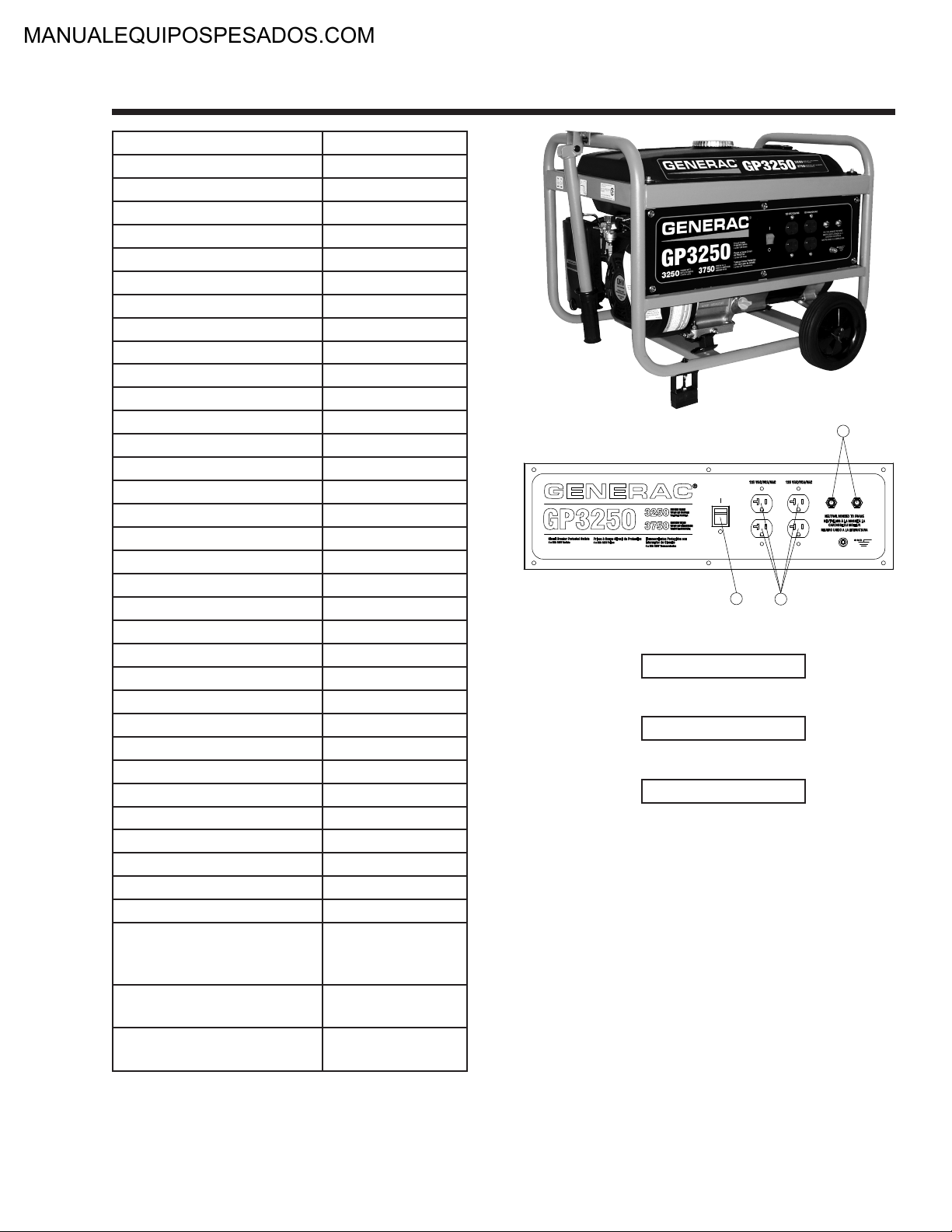
Product Series GP3250
A/C Rated Output Watts: 3250
A/C Maximum Output Watts: 3750
A/C Voltage 120VAC
A/C Frequency 60 Hz
Rated 120 VAC Amperage 13.5
Max 120 VAC Amperage 15.6
Engine Displacement 206cc
Engine Type OHV
Engine RPM 3600
Recommended Oil 5W30
Lubrication Method Splash Sump
Choke Type Manual Lever
Fuel Shut Off Manual Lever
Idle Control Full Speed
Starting Method Manual
Battery n/a
Battery Size n/a
Low Oil Shutdown Method Low Level
Start Switch Type On/Off Toggle
Switch Location Control Panel
Single-Point Lifting Eye N/A
Fuel Gauge Built-In
Fuel Tank Capacity (Gal) 4
Fuel Tank Capacity (Liters) 15.14
Run Time at 50% (Hours) 13.5
Cord Set No
Handle Style Folding
Wheel type 7.0" Solid Wheels
Length (L) 25.5
Width (W) 21
Height (H) 19
Extended Length (EL) 39.5
Unit Weight (lbs) 91
Spark Plug Type NGK BPR4ES
or Champion
RN14YC
Spark Plug Gap 0.028"-0.031"
(0.7-0.8mm)
Oil Capacity 0.634 quart
(0.6 liter)
SPECIFICATIONS – GP3250
Outlets
A
Circuit Breakers
M
Other Features
H
(4) 5-20R 120V
(2) 20A
On/Off Switch
Page 3
Page 6
H
B
N
M
A
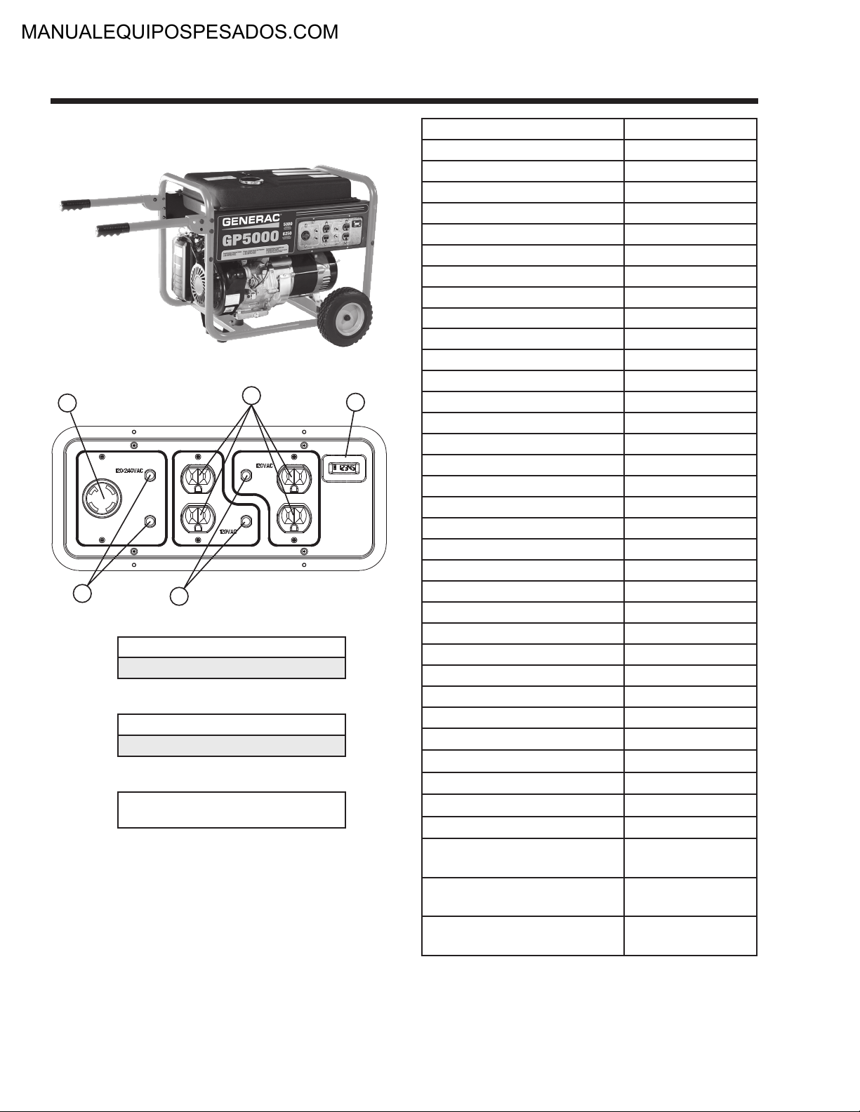
SPECIFICATIONS – GP5000
Receptacles
A
B
Circuit Breakers
M
N
Other Features
H
(4) 5-20R 120V
L14-30R Twist-Lock 120/240V
(2) 20A
(2) 25A
Hour Meter with
Maintenance Reset
Product Series GP5000
A/C Rated Output Watts: 5000
A/C Maximum Output Watts: 6250
A/C Voltage 120/240VAC
A/C Frequency 60 Hz
Rated 120/240 VAC Amperage 20.8
Max 120/240 VAC Amperage 26.0
Engine Displacement 389cc
Engine Type OHV
Engine RPM 3600
Recommended Oil 5W30
Lubrication Method Splash Sump
Choke Type Manual Lever
Fuel Shut Off Manual Lever
Idle Control Full Speed
Starting Method Manual
Battery n/a
Battery Size n/a
Low Oil Shutdown Method Low Level
Start Switch Type 3-Position
Switch Location On Engine
Single-Point Lifting Eye N/A
Fuel Gauge Built-In
Fuel Tank Capacity (Gal) 6.6
Fuel Tank Capacity (Liters) 24.981
Run Time at 50% (Hours) 10
Cord Set No
Handle Style Folding Interlocked
Wheel type 9.5" Solid Wheels
Length (L) 33.5
Width (W) 26.5
Height (H) 27.5
Extended Length (EL) 47
Unit Weight (lbs) 167
Spark Plug Type NHSP F7RTC or
Champion RN9YC
Spark Plug Gap 0.028"-0.031"
(0.7-0.8mm)
Oil Capacity 1.16 quart
(1.1 liter)
Page 4
Page 7
H
B
N
M
A
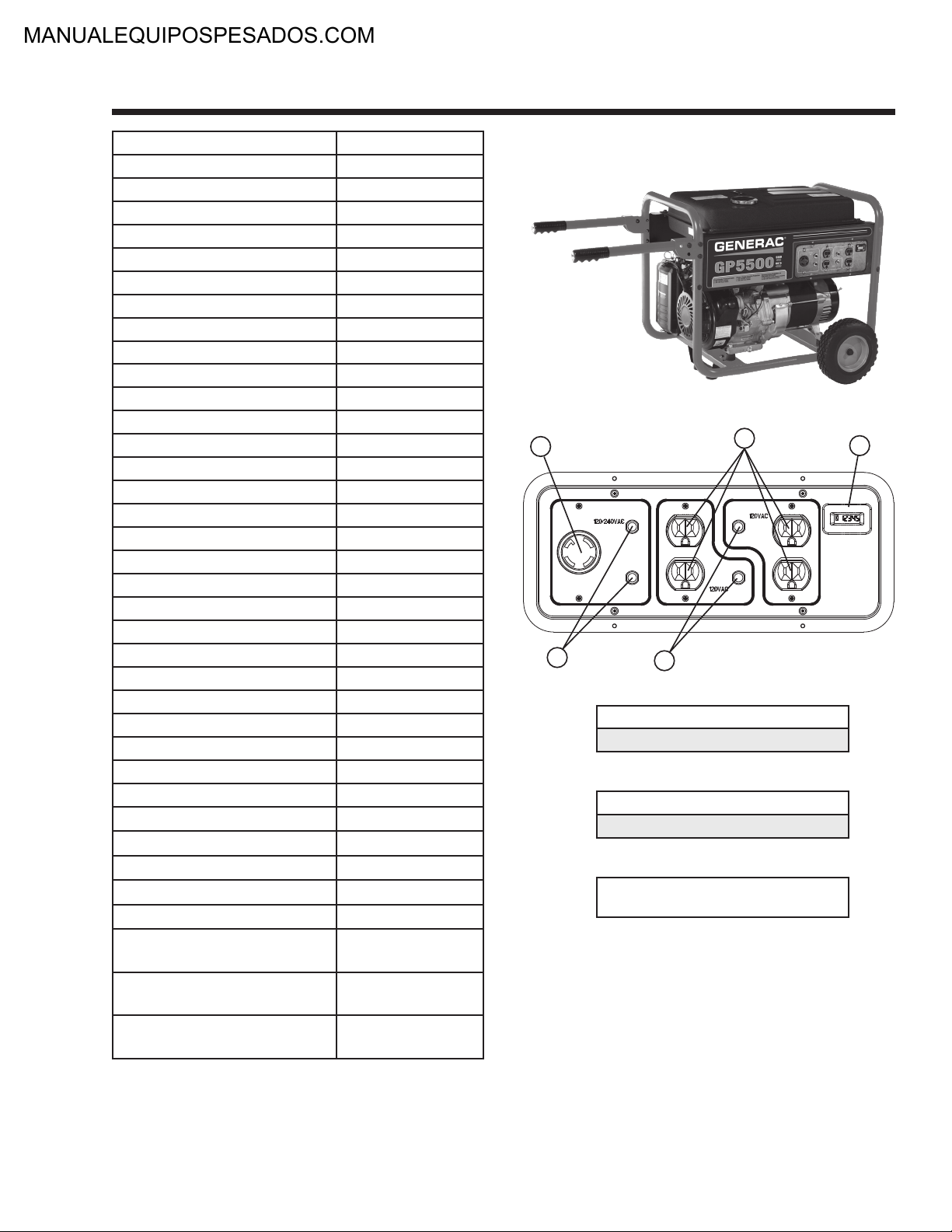
Product Series GP5500
A/C Rated Output Watts: 5000
A/C Maximum Output Watts: 6875
A/C Voltage 120/240VAC
A/C Frequency 60 Hz
Rated 120/240 VAC Amperage 22.9
Max 120/240 VAC Amperage 28.6
Engine Displacement 389cc
Engine Type OHV
Engine RPM 3600
Recommended Oil 5W30
Lubrication Method Splash Sump
Choke Type Manual Lever
Fuel Shut Off Manual Lever
Idle Control Full Speed
Starting Method Manual
Battery n/a
Battery Size n/a
Low Oil Shutdown Method Low Level
Start Switch Type 3-Position
Switch Location On Engine
Single-Point Lifting Eye N/A
Fuel Gauge Built-In
Fuel Tank Capacity (Gal) 6.6
Fuel Tank Capacity (Liters) 24.98
Run Time at 50% (Hours) 10
Cord Set No
Handle Style Folding Interlocked
Wheel type 9.5" Solid Wheels
Length (L) 33.5
Width (W) 26.5
Height (H) 27.5
Extended Length (EL) 47
Unit Weight (lbs) 167
Spark Plug Type NHSP F7RTC or
Champion RN9YC
Spark Plug Gap 0.028"-0.031"
Oil Capacity 1.16 quart
(0.7-0.8mm)
(1.1 liter)
SPECIFICATIONS – GP5500
Receptacles
A
B
Circuit Breakers
M
N
Other Features
H
(4) 5-20R 120V
L14-30R Twist-Lock 120/240V
(2) 20A
(2) 25A
Hour Meter with
Maintenance Reset
Page 5
Page 8
H
B
N
M
A
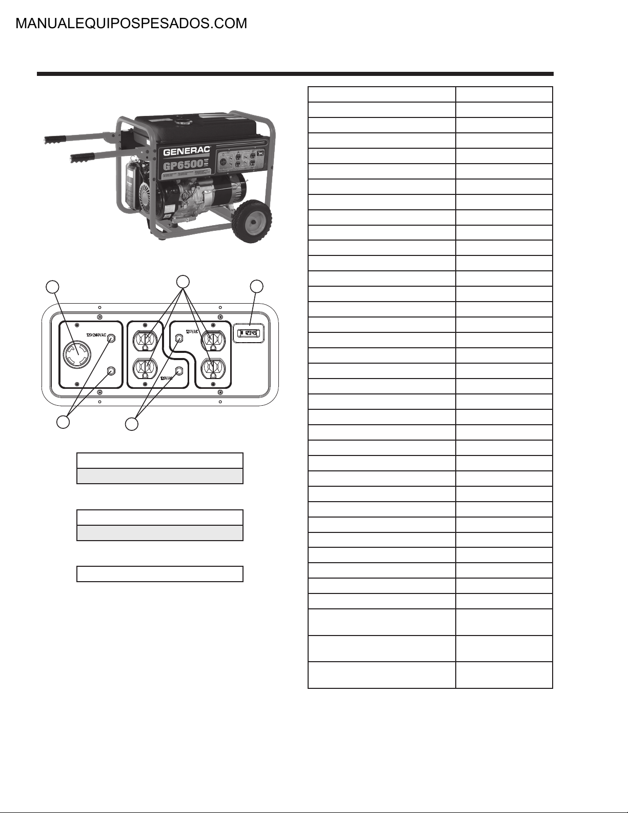
SPECIFICATIONS – GP6500
Outlets
A
B
Circuit Breakers
M
N
Other Features
H
Hour Meter with Maintenance Reset
(4) 5-20R 120V
L14-30R Twist-Lock 120/240V
(2) 20A
(2) 30A
Product Series GP6500
A/C Rated Output Watts: 6500
A/C Maximum Output Watts: 8000
A/C Voltage 120/240VAC
A/C Frequency 60 Hz
Rated 120/240 VAC Amperage 27.1
Max 120/240 VAC Amperage 33.3
Engine Displacement 389cc
Engine Type OHV
Engine RPM 3600
Recommended Oil 5W30
Lubrication Method Splash Sump
Choke Type Manual Lever
Fuel Shut Off Manual Lever
Idle Control Full Speed
Starting Method Manual
Battery n/a
Battery Size n/a
Low Oil Shutdown Method Low Level
Start Switch Type 3-Position
Switch Location On Engine
Single-Point Lifting Eye N/A
Fuel Gauge Built-In
Fuel Tank Capacity (Gal) 6.6
Fuel Tank Capacity (Liters) 24.98
Run Time at 50% (Hours) 9
Cord Set No
Handle Style Folding Interlocked
Wheel type 9.5" Solid Wheels
Length (L) 33.5
Width (W) 26.5
Height (H) 27.5
Extended Length (EL) 47
Unit Weight (lbs) 172
Spark Plug Type NHSP F7RTC or
Champion RN9YC
Spark Plug Gap 0.028"-0.031"
(0.7-0.8mm)
Oil Capacity 1.16 quart
(1.1 liter)
Page 6
Page 9
H
B
N
M
A
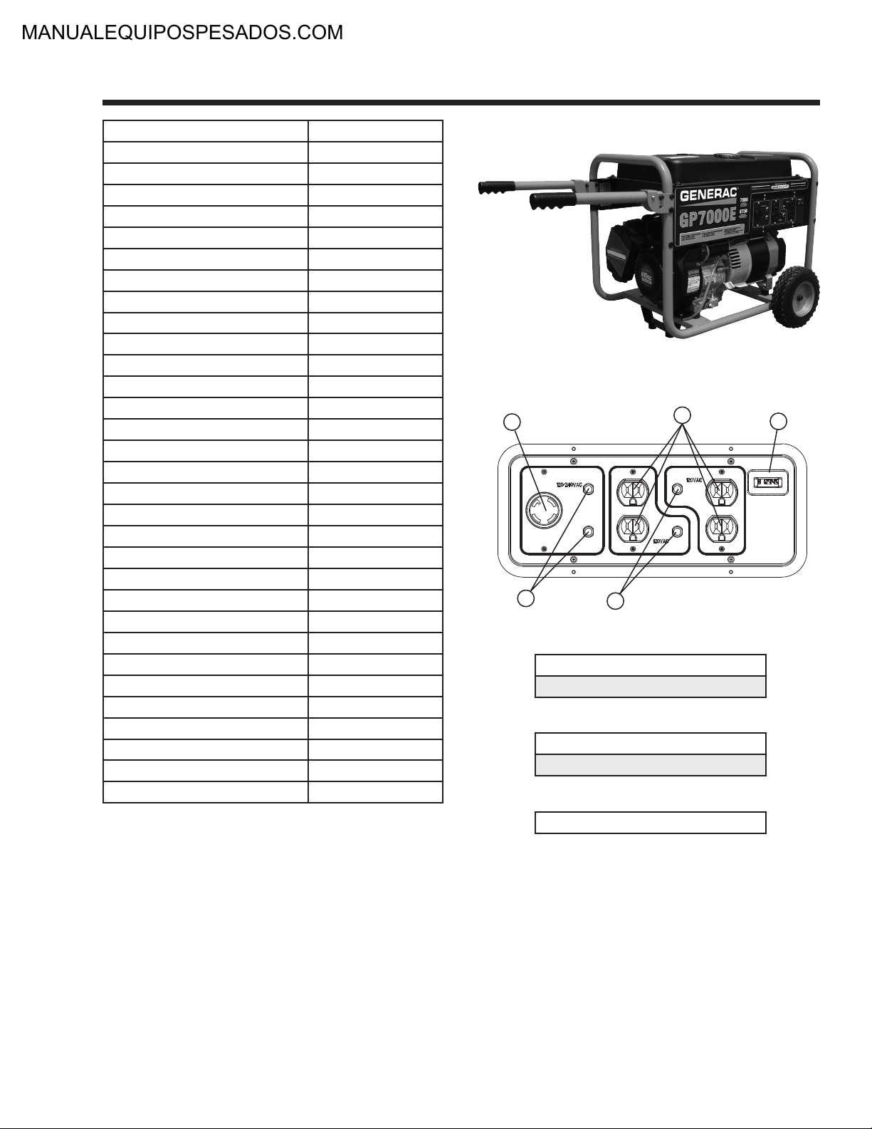
Product Series GP7000
A/C Rated Output Watts: 7000
A/C Maximum Output Watts: 8750
A/C Voltage 120/240VAC
A/C Frequency 60 Hz
Rated 120/240 VAC Amperage 29.2
Max 120/240 VAC Amperage 36.5
Engine Displacement 410cc
Engine Type OHVI
Engine RPM 3600
Recommended Oil 5W30
Lubrication Method Full Pressure
Choke Type Manual Lever
Fuel Shut Off Manual Lever
Idle Control Full Speed
Starting Method GP7000 Manual
Starting Method GP7000E Manual or Electric
Battery Size (if equipped) 12VDC 10 Ahr
Low Oil Shutdown Method Low Pressure
Start Switch Type 3-Position
Switch Location On Engine
Single-Point Lifting Eye N/A
Fuel Gauge Built-In
Fuel Tank Capacity (Gal) 8
Fuel Tank Capacity (Liters) 30.28
Run Time at 50% (Hours) 11
Cord Set No
Handle Style Folding Interlocked
Wheel type 9.5" Solid Wheels
Spark Plug Type Champion RC14YC
Spark Plug Gap 0.030" (0.76mm)
Oil Capacity 1.5 quart w/filter
SPECIFICATIONS – GP7000/GP7000E
Outlets
A
B
Circuit Breakers
M
N
Other Features
H
Hour Meter with Maintenance Reset
(4) 5-20R 120V
L14-30R Twist-Lock 120/240V
(2) 20A
(2) 30A
Page 7
Page 10

H
B
N
M
A
SPECIFICATIONS – GP8000/GP8000E
Outlets
A
B
Circuit Breakers
M
N
Other Features
H
Hour Meter with Maintenance Reset
(4) 5-20R 120V
L14-30R Twist-Lock 120/240V
(2) 20A
(2) 30A
Product Series GP8000/GP8000E
A/C Rated Output Watts: 8000
A/C Maximum Output Watts: 10000
A/C Voltage 120/240VAC
A/C Frequency 60 Hz
Rated 120/240 VAC Amperage 33.3
Max 120/240 VAC Amperage 41.7
Engine Displacement 410cc
Engine Type OHVI
Engine RPM 3600
Recommended Oil 5W30
Lubrication Method Full Pressure
Choke Type Manual Lever
Fuel Shut Off Manual Lever
Idle Control Full Speed
Starting Method GP8000 Manual
Starting Method GP8000E Manual or Electric
Battery Size (if equipped) 12VDC 10 Ahr
Low Oil Shutdown Method Low Pressure
Start Switch Type 3-Position
Switch Location On Engine
Single-Point Lifting Eye N/A
Fuel Gauge Built-In
Fuel Tank Capacity (Gal) 8
Fuel Tank Capacity (Liters) 30.28
Run Time at 50% (Hours) 8
Cord Set No
Handle Style Folding Interlocked
Wheel type 9.5" Solid Wheels
Spark Plug Type Champion RC14YC
Spark Plug Gap 0.030" (0.76mm)
Oil Capacity 1.5 quart w/filter
Page 8
Page 11

PART 1
GENERAL
INFORMATION
GP Series Portable Generators
TABLE OF CONTENTS
PART TITLE PAGE
1.1 Generator Fundamentals 10
1.2 Measuring Electricity 13
1.3 Brushless, Capacitor Excitation
System
1.4 Brushed Excitation System 18
1.5 Testing, Cleaning and Drying 20
16
Part 1 – General Information .................................. 9
Section 1.1 – Generator Fundamentals ................ 10
Magnetism .......................................................10
Electromagnetic Fields.....................................10
Electromagnetic Induction................................10
A Simple AC Generator ...................................11
A More Sophisticated AC Generator ................11
Section 1.2 – Measuring Electricity ....................... 13
Meters ............................................................13
The VOM ..........................................................13
Measuring AC Voltage .....................................13
Measuring DC Voltage .....................................13
Measuring AC Frequency ................................13
Measuring Current ...........................................14
Measuring Resistance .....................................14
Electrical Units .................................................15
Ohm's Law .......................................................15
Section 1.3 – Brushless, Capacitor
Excitation System ............................ 16
Introduction ......................................................16
Stator Assembly ...............................................16
Rotor Assembly ................................................16
Circuit Breakers ...............................................16
Operation .........................................................17
Section 1.4 – Brushed Excitation System ............. 18
Introduction ......................................................18
Stator Assembly ...............................................18
Brush Holder and Brushes ...............................18
Rotor Residual Magnetism...............................18
Voltage Regulator ............................................18
Operation .........................................................18
Section 1.5 – Testing, Cleaning and Drying .......... 20
Insulation Resistance .......................................20
The Megohmmeter...........................................20
Stator Insulation Resistance Test .....................20
Cleaning the Generator ....................................21
Drying the Generator .......................................21
Page 9
Page 12

SECTION 1.1
GENERATOR FUNDAMENTALS
MAGNETISM
Magnetism can be used to produce electricity and
electricity can be used to produce magnetism.
Much about magnetism cannot be explained by our
present knowledge. However, there are certain patterns of behavior that are known. Application of these
behavior patterns has led to the development of generators, motors and numerous other devices that utilize magnetism to produce and use electrical energy.
See Figure 1. The space surrounding a magnet is permeated by magnetic lines of force called “flux”. These
lines of force are concentrated at the magnet's north
and south poles. They are directed away from the
magnet at its north pole, travel in a loop and re-enter
the magnet at its south pole. The lines of force form
definite patterns which vary in intensity depending on
the strength of the magnet. The lines of force never
cross one another. The area surrounding a magnet in
which its lines of force are effective is called a “magnetic field”.
Like poles of a magnet repel each other, while unlike
poles attract each other.
PART 1
NOTE: The “right hand rule” is based on the “current flow” theory which assumes that current
flows from positive to negative. This is opposite
the “electron” theory, which states that current
flows from negative to positive.
Figure 2. The Right Hand Rule
GENERAL INFORMATION
Figure 1. Magnetic Lines of Force
ELECTROMAGNETIC FIELDS
All conductors through which an electric current is
flowing have a magnetic field surrounding them. This
field is always at right angles to the conductor. If a
compass is placed near the conductor, the compass
needle will move to a right angle with the conductor.
The following rules apply:
• Thegreater thecurrent flowthrough theconductor,
the stronger the magnetic field around the conductor.
• The increase inthe number of linesof force is
directly proportional to the increase in current flow
and the field is distributed along the full length of
the conductor.
• Thedirectionofthelinesofforcearoundaconductor can be determined by what is called the “right
hand rule”. To apply this rule, place your right hand
around the conductor with the thumb pointing in
the direction of current flow. The fingers will then be
pointing in the direction of the lines of force.
ELECTROMAGNETIC INDUCTION
An electromotive force (EMF) or voltage can be produced in a conductor by moving the conductor so that
it cuts across the lines of force of a magnetic field.
Similarly, if the magnetic lines of force are moved so
that they cut across a conductor, an EMF (voltage)
will be produced in the conductor. This is the basic
principal of the revolving field generator.
Figure 3, below, illustrates a simple revolving field
generator. The permanent magnet (Rotor) is rotated
so that its lines of magnetic force cut across a coil of
wires called a Stator. A voltage is then induced into
the Stator windings. If the Stator circuit is completed
by connecting a load (such as a light bulb), current
will flow in the circuit and the bulb will light.
Figure 3. A Simple Revolving Field Generator
Page 10
Page 13

S
TATOR
ROT
OR
MAGNETIC FIEL
D
CURRENT
VOLTAGE
ONE CYCLE
0
180
360
(+)
(-)
STATOR
ROTOR
GENERATOR
120 VAC
120 VAC
+
-
AC OUTPUT
STATOR
240 VAC
CAPACITOR
STATOR
BRUSHES
120 V
120 V
+
-
SLIP
RINGS
AC OUTPUTDC CURRENT
STATOR
240 V
GENERAL INFORMATION
PART 1
A SIMPLE AC GENERATOR
Figure 4 shows a very simple AC Generator. The generator consists of a rotating magnetic field called a
ROTOR and a stationary coil of wire called a STATOR.
The ROTOR is a permanent magnet which consists of
a SOUTH magnetic pole and a NORTH magnetic pole.
As the MOTOR turns, its magnetic field cuts across
the stationary STATOR. A voltage is induced Into
the STATOR windings. When the magnet's NORTH
pole passes the STATOR, current flows in one direction. Current flows in the opposite direction when the
magnet's SOUTH pole passes the STATOR. This constant reversal of current flow results in an alternating
current (AC) waveform that can be diagrammed as
shown in Figure 5.
The ROTOR may be a 2-pole type having a single
NORTH and a single SOUTH magnetic pole. Some
ROTORS are 4-pole type with two SOUTH and two
NORTH magnetic poles. The following apply:
1. The 2-pole ROTOR must be turned at 3600 rpm to produce an AC frequency of 60 Hertz, or at 3000 rpm to
deliver an AC frequency of 50 Hertz.
SECTION 1.1
GENERATOR FUNDAMENTALS
A MORE SOPHISTICATED AC GENERATOR
Figure 6 and 7 show two methods of creating alternating current that are implemented on GP Series portable generator product.
Figure 6 shows a consistent voltage being induced to
the rotor from a capacitor which is installed in series
with the DPE winding. As a result a regulated voltage
is induced into the STATOR.
2. The 4-pole ROTOR must operate at 1800 rpm to deliver
a 60 Hertz AC frequency or at 1500 rpm to deliver a 50
Hertz AC frequency.
Figure 4. A Simple AC Generator
Figure 6. Capacitive Discharge
Figure 7 shows a regulated direct current being delivered into the ROTOR windings via carbon BRUSHES
AND SLIP RINGS. This results in the creation of
a regulated magnetic field around the ROTOR. As
a result, a regulated voltage is induced into the
STATOR. Regulated current delivered to the ROTOR
is called “EXCITATION” current.
Figure 5. Alternating Current Sine Wave
Figure 7. Direct Excitation
Page 11
Page 14

CAPACITOR
STATOR
EXCITATION
WINDING
STATOR
POWER
WINDING
STATOR
POWER
WINDING
MAGNETIC
FIELD
MAGNETIC
FIELD
MLB = MAIN LINE
CIRCUIT BREAKER
ROTOR
TO LOAD
MLB
ENGINE DIRECT
DRIVE
AUTOMATIC
VOLTAGE
REGULATOR
+-
STATOR
EXCITATION
WINDING
STATOR
POWER
WINDING
STATOR
POWER
WINDING
MAGNETIC
FIELD
MAGNETIC
FIELD
SENSING
MLB = MAIN LINE
CIRCUIT BREAKER
ROTOR
TO LOAD
MLB
ENGINE DIRECT
DRIVE
120 VAC 120 VAC
240 VAC
120 VAC 120 VAC
240 VAC
A B
CAPACITIVE DISCHARGE DIRECT EXCITATION
SECTION 1.1
GENERATOR FUNDAMENTALS
PART 1
GENERAL INFORMATION
Figure 8. Generator Operating Diagram
The revolving magnetic field is driven by the engine
at constant speed. This constant speed is maintained
by a mechanical engine governor. Units with a 2-pole
rotor require an operation speed of 3600 rpm to deliver a 60 Hertz AC output.
Generator operation may be described briefly as follows.
1. Some “residual” magnetism is normally present in the
Rotor, which is sufficient to induce approximately 1 to 2
Volts AC in to the Stator’s AC Power Windings and DPE
winding.
2. See Figure 8.
A. Dur ing startup, the “residual” voltage that
is induced into the DPE winding will initially
charge the capacitor to a greater potential.
When the capacitor is discharged the voltage
is in turn induced back into the Rotor which will
exponen tially raise the voltage to 120/240.
B. During startup, the “residual” voltage that is
induced into the DPE winding will turn on the
voltage regulator allowing DC excitation current
to be delivered to the rotor and raise the voltage
to 120/240.
Page 12
Page 15

GENERAL INFORMATION
PART 1
METERS
Devices used to measure electrical properties are called
meters. Meters are available that allow one to measure
(a) AC voltage, (b) DC voltage, (c) AC frequency, and
(d) resistance in ohms. The following apply:
• TomeasureACvoltage,useanACvoltmeter.
• TomeasureDCvoltage,useaDCvoltmeter.
• UseafrequencymetertomeasureACfrequencyin
“Hertz” or “cycles per second”.
• Use an ohmmeter to read circuit resistance, in
“Ohms”.
THE VOM
A meter that will permit both voltage and resistance to
be read is the “volt-ohm-milliammeter” or “VOM”.
Some VOMs are of the “analog” type (not shown).
These meters display the value being measured by
physically deflecting a needle across a graduated
scale. The scale used must be interpreted by the user.
“Digital” VOMs (Figure 1) are also available and are
generally very accurate. Digital meters display the
measured values directly by converting the values to
numbers.
NOTE: Standard AC volt me te rs react to the
AVERAGE value of alternating current. When working with AC, the effective value is used. For that
reason a different scale is used on an AC voltmeter. The scale is marked with the effective or “rms”
value even though the meter actually reacts to the
average value. That is why the AC voltmeter will
give an incorrect reading if used to measure direct
current (DC).
SECTION 1.2
MEASURING ELECTRICITY
MEASURING AC VOLTAGE
An accurate AC voltmeter or a VOM may be used to
read the generator's AC output voltage. The following
apply:
1. Always read the generator's AC output voltage only at
the unit's rated operating speed and AC frequency.
2. The generator's Voltage Regulator can be adjusted for
correct output voltage only while the unit is operating at
its correct rated speed and frequency.
3. Only an AC voltmeter may be used to measure AC
voltage. DO NOT USE A DC VOLTMETER FOR THIS
PURPOSE.
DANGER! GENERATORS PRODUCE HIGH
AND DANGEROUS VOLTAGES. CONTACT
*
WITH HIGH VOLTAGE TERMINALS WILL
RESULT IN DANGEROUS AND POSSIBLY
LETHAL ELECTRICAL SHOCK.
MEASURING DC VOLTAGE
A DC voltmeter or a VOM may be used to measure
DC voltages. Always observe the following rules:
1. Always observe correct DC polarity.
a. Some VOM's may be equipped with a polar-
ity switch.
b. On meters that do not have a polarity switch,
DC polarity must be reversed by reversing
the test leads.
2. Before reading a DC voltage, always set the meter to a
higher voltage scale than the anticipated reading. If in
doubt, start at the highest scale and adjust the scale
downward until correct readings are obtained.
Figure 1. Digital VOM
3. The design of some meters is based on the “current
flow” theory while others are based on the “electron flow”
theory.
a. The “current flow” theory assumes that direct
current flows from the positive (+) to the
negative (-).
b. The “electron flow” theory assumes that cur-
rent flows from negative (-) to positive (+).
NOTE: When testing generators, the “current flow”
theory is applied. That is, current is assumed to
flow from positive (+) to negative (-).
MEASURING AC FREQUENCY
The generator's AC output frequency is proportional to
Rotor speed. Generators equipped with a 2-pole Rotor
must operate at 3600 rpm to supply a frequency of 60
Hertz. Units with 4-pole Rotor must run at 1800 rpm to
deliver 60 Hertz.
Page 13
Page 16

1.00 A
BATTERY
+-
RELAY
SECTION 1.2
MEASURING ELECTRICITY
Correct engine and Rotor speed is maintained by an
engine speed governor. For models rated 60 Hertz,
the governor is generally set to maintain a no-load frequency of about 62 Hertz with a corresponding output
voltage of about 124 volts AC line-to-neutral. Engine
speed and frequency at no-load are set slightly high
to prevent excessive rpm and frequency droop under
heavy electrical loading.
MEASURING CURRENT
CLAMP-ON:
To read the current flow, in AMPERES, a clamp-on
ammeter may be used. This type of meter indicates
current flow through a conductor by measuring the
strength of the magnetic field around that conductor.
The meter consists essentially of a current transformer with a split core and a rectifier type instrument connected to the secondary. The primary of the current
transformer is the conductor through which the current
to be measured flows. The split core allows the instrument to be clamped around the conductor without
disconnecting it.
Current flowing through a conductor may be measured
safely and easily. A line-splitter can be used to measure
current in a cord without separating the conductors.
PART 1
NOTE: If the physical size of the conductor or ammeter capacity does not permit all lines to be measured
simultaneously, measure current flow in each individual line. Then, add the individual readings.
IN-LINE:
Alternatively, to read the current flow in AMPERES, an
in-line ammeter may be used. Most Digital Volt Ohm
Meters (VOM) will have the capability to measure
amperes.
This usually requires the positive meter test lead to be
connected to the correct amperes plug, and the meter
to be set to the amperes position. Once the meter is
properly set up to measure amperes the circuit being
measured must be physically broken. The meter will
be in-line or in series with the component being measured.
In Figure 4 the control wire to a relay has been
removed. The meter is used to connect and supply
voltage to the relay to energize it and measure the
amperes going to it.
GENERAL INFORMATION
Page 14
Figure 2. Clamp-On Ammeter
Figure 3. A Line-Splitter
Figure 4. A VOM as an In-line meter
MEASURING RESISTANCE
The volt-ohm-milliammeter may be used to measure
the resistance in a circuit. Resistance values can be
very valuable when testing coils or windings, such as
the Stator and Rotor windings.
When testing Stator windings, keep in mind that the
resistance of these windings is very low. Some meters
are not capable of reading such a low resistance and
will simply read CONTINUITY.
If proper procedures are used, the following conditions
can be detected using a VOM:
• A“short-to-ground”condition inanyStatoror Rotor
winding.
•
Shorting together of any two parallel Stator windings.
•
Shorting together of any two isolated Stator windings.
• AnopenconditioninanyStatororRotorwinding.
Page 17

-
+
AMPERE - Unit measuring rate of
current flow (number of electrons
past a given point)
OHM - Unit measuring resistance
or opposition to flow
VOLT - Unit measuring force or
difference in potential
causing current flow
Conductor of a
Circuit
VOLTS
(E)
AMPS
(I)
OHMS
(R)
GENERAL INFORMATION
Component testing may require a specific resistance value or a test for INFINITY or CONTINUITY.
Infinity is an OPEN condition between two electrical
points, which would read as no resistance on a VOM.
Continuity is a CLOSED condition between two electrical points, which would be indicated as very low resistance or “ZERO” on a VOM.
PART 1
ELECTRICAL UNITS
AMPERE:
The rate of electron flow in a circuit is represented
by the AMPERE. The ampere is the number of electrons flowing past a given point at a given time. One
AMPERE is equal to just slightly more than six thousand million billion electrons per second (6.25 x 10¹⁸).
With alternating current (AC), the electrons flow first in
one direction, then reverse and move in the opposite
direction. They will repeat this cycle at regular intervals. A wave diagram, called a “sine wave” shows that
current goes from zero to maximum positive value,
then reverses and goes from zero to maximum negative value. Two reversals of current flow is called a
cycle. The number of cycles per second is called frequency and is usually stated in “Hertz”.
SECTION 1.2
MEASURING ELECTRICITY
OHM:
The OHM is the unit of RESISTANCE. In every circuit
there is a natural resistance or opposition to the flow
of electrons. When an EMF is applied to a complete
circuit, the electrons are forced to flow in a single
direction rather than their free or orbiting pattern. The
resistance of a conductor depends on (a) its physical
makeup, (b) its cross-sectional area, (c) its length, and
(d) its temperature. As the conductor's temperature
increases, its resistance increases in direct proportion.
One (1) ohm of resistance will permit one (1) ampere
of current to flow when one (1) volt of electromotive
force (EMF) is applied.
OHM'S LAW
A definite and exact relationship exists between VOLTS,
OHMS and AMPERES. The value of one can be calculated when the value of the other two are known. Ohm's
Law states that in any circuit the current will increase
when voltage increases but resistance remains the
same, and current will decrease when resistance
Increases and voltage remains the same.
VOLT :
The VOLT is the unit used to measure electrical
PRESSURE, or the difference in electrical potential
that causes electrons to flow. Very few electrons will
flow when voltage is weak. More electrons will flow as
voltage becomes stronger. VOLTAGE may be considered to be a state of unbalance and current flow as
an attempt to regain balance. One volt is the amount
of EMF that will cause a current of 1 ampere to flow
through 1 ohm of resistance.
Figure 5. Electrical Units
Figure 6. Ohm's Law
If AMPERES is unknown while VOLTS and OHMS are
known, use the following formula:
OHMS
If VOLTS is unknown while AMPERES and OHMS are
known, use the following formula:
If OHMS is unknown but VOLTS and AMPERES are
known, use the following:
AMPERES
AMPERES =
VOLTS = AMPERES x OHMS
OHMS
VOLTS
VOLTS
=
Page 15
Page 18

STATOR
ROTOR
ENGINE
CAPACITOR
DIODE B
COIL 2
COIL 1
DIODE A
CAPACITOR
STATOR
EXCITATION
WINDING
STATOR
POWER
WINDING
STATOR
POWER
WINDING
MAGNETIC
FIELD
MAGNETIC
FIELD
MLB = MAIN LINE
CIRCUIT BREAKER
ROTOR
TO LOAD
MLB
ENGINE DIRECT
DRIVE
AUTOMATIC
VOLTAGE
REGULATOR
+-
STATOR
EXCITATION
WINDING
STATOR
POWER
WINDING
STATOR
POWER
WINDING
MAGNETIC
FIELD
MAGNETIC
FIELD
SENSING
MLB = MAIN LINE
CIRCUIT BREAKER
ROTOR
TO LOAD
MLB
ENGINE -
DIRECT
DRIVE
120 VAC 120 VAC
240 VAC
120 VAC 120 VAC
240 VAC
SECTION 1.3
BRUSHLESS, CAPACITOR EXCITATION SYSTEM
INTRODUCTION
A typical brushless type portable generator will need
4 major components to function—a prime mover, a
stator, a rotor, and a capacitor.
As the engine starts to crank, residual magnetism
from the rotor creates magnetic lines of flux. The
lines begin to cut the excitation winding and induce
a small voltage into the winding. The voltage causes
the capacitor to charge. When the capacitor has fully
charged it will discharge a voltage that will be induced
back into the rotor. The AC voltage induced into the
rotor is rectified using a diode. The magnetic lines of
flux from the rotor will increase, causing output voltage to increase. The charge and discharge relationship that the capacitor and rotor share is the voltage
regulation system that allows the generator to maintain 240 volts.
Figure 1 shows the major components of a typical GP
Series brushless AC generator.
a tapered crankshaft and is held in place with a single
through bolt.
Note: Some Rotors have a magnet placed inside
to help excite the rotor after it has been left idle
for a long period of time.
PART 1
GENERAL INFORMATION
The stator has three windings wound separately
inside the can. Two are the power windings and are
located on Wire 44 (Hot) and Wire 33 (Neutral), the
other winding is located on Wire 11 (Hot) and Wire 22
(Neutral). The third winding is called the DPE winding
or Displaced Phase Excitation winding and is located
on Wire 2 and Wire 6.
The 2-pole rotor must be operated at 3600 rpm to
supply a 60 Hertz AC frequency. The term “2-pole”
means the rotor has a single north magnetic pole and
a single south magnetic pole. It spins freely inside
the stator can and is excited by the charging and discharging of the capacitor. It has two diodes that rectify voltage induced from the Excitation winding to DC
voltage. The rotor bearing is pressed onto the end of
the rotor shaft. The tapered rotor shaft is mounted to
Page 16
Figure 1. AC Generator Exploded View
STATOR ASSEMBLY
ROTOR ASSEMBLY
Figure 2. Rotor and Diodes
CIRCUIT BREAKERS
Each individual circuit on the generator is protected
by a circuit breaker to prevent overload.
Figure 3. Generator Operating Diagram
Page 19

CAPACITOR 28µf
WIRE 2
WIRE 6
RED (R2 – 33)
BLUE (R1 – 44)
BROWN (L2 – 22)
WHITE (L1 – 11)
WIRE 2
WIRE 6
11 22 33 44
CAPACITOR 47µf (440 VAC)
GENERAL INFORMATION
PART 1
BRUSHLESS, CAPACITOR EXCITATION SYSTEM
OPERATION
STARTUP:
When the engine is started, residual magnetism from
the rotor induces a voltage into (a) the stator AC
power windings, (b) the stator excitation or DPE windings. In an “On-speed” (engine cranking) condition,
residual magnetism is capable of creating approximately one to three Volts AC.
ON-SPEED OPERATION:
As the engine accelerates, the voltage that is induced
into the stator windings increases rapidly, due to the
increasing speed at which the rotor operates.
SECTION 1.3
FIELD EXCITATION:
An AC voltage is induced into the stator excitation
(DPE) windings. The DPE winding circuit is completed
to the capacitor where the charging and discharging
causes a voltage to be induced back in to the rotor
which will regulate voltage. The greater the current
flow through the rotor windings, the more concentrated the lines of flux around the rotor become. The
more concentrated the lines of flux around the rotor
that cut across the stationary stator windings, the
greater the voltage that is induced into the stator
windings. Initially, the AC power winding voltage is
low, but as the capacitor is charged and discharged
this relationship between the rotor and the capacitor
is what will regulate voltage at a desired level.
AC POWER WINDING OUTPUT:
A regulated voltage is induced into the stator AC
power windings. When electrical loads are connected
across the AC power windings to complete the circuit,
current can flow in the circuit.
A
Figure 4. Alternator Configuration A
B
Figure 5. Alternator Configuration B
Page 17
Page 20

STATOR
ROTOR
ENGINE
BRUSHES
VOLTAGE REGULATOR
Section 1.4
BRUSHED EXCITATION SYSTEM
INTRODUCTION
A typical brushed type portable generator will need 4
major components to function: a prime mover, a stator, a rotor, and a voltage regulator.
As the engine starts to crank, residual magnetism
from the rotor creates magnetic lines of flux. The lines
begin to cut the excitation winding and induce a small
voltage into the voltage regulator. The excitation voltage will power the voltage regulator and the voltage
regulator will start to sense AC voltage from Wires
S15 and S16. The lower voltage from the sensing
wires will cause DC excitation to the rotor to be driven
up until AC output is at desired level of 240VAC. Once
the generator has reached 240VAC it will maintain the
DC voltage, regulating the alternator when loads are
applied and removed.
PART 1
to the negative (-) slip ring and brush on Wire 0. This
current flow creates a magnetic field around the rotor
having a flux concentration that is proportional to the
amount of current flow.
GENERAL INFORMATION
ROTOR RESIDUAL MAGNETISM
The generator revolving field (rotor) may be considered to be a permanent magnet. Some “residual”
magnetism is always present in the rotor. This residual magnetism is sufficient to induce a voltage into the
stator AC power windings that is approximately 2-5
volts AC.
Note: Some Rotors have a magnet placed inside
to help excite the rotor after it has been left idle
for a long period of time.
VOLTAGE REGULATOR
Refer to Figure 3 for the proper identification of the
voltage regulator. Unregulated AC output from the
stator excitation winding is delivered to the regulator’s
DPE terminals, via Wire 2 and Wire 6. The voltage
regulator rectifies that current and, based on stator
AC power winding sensing, regulates it. The rectified
and regulated excitation current is then delivered to
the rotor windings from the positive (+) and negative
(-) regulator terminals, via Wire 4 and Wire 0. Stator
AC power winding “sensing” is delivered to the regulator via Wires S15 and S16.
Figure 1. AC Generator Exploded View
STATOR ASSEMBLY
The stator has three windings wound separately
inside the can. Two are the power windings and are
located on Wire 44 (Hot) and Wire 33 (Neutral); the
other winding is located on Wire 11 (Hot) and Wire 22
(neutral). The third winding is called DPE winding or
Displaced Phase Excitation winding and is located on
Wire 2 and Wire 6.
BRUSH HOLDER AND BRUSHES
The brush holder is retained to the rear bearing carrier by means of two Taptite screws. A positive (+) and
a negative (-) brush are retained in the brush holder.
Wire 4 connects to the positive (+) brush and Wire
0 to the negative (-) brush. Rectified and regulated
excitation current are delivered to the rotor windings
via Wire 4, and the positive (+) brush and slip ring.
The excitation current passes through the windings
Page 18
OPERATION
STARTUP:
When the engine is started, residual magnetism from
the rotor induces a voltage into (a) the stator AC
power windings, (b) the stator excitation or DPE windings. In an “on-speed” (engine cranking) condition,
residual magnetism is capable of creating approximately one to three volts AC.
ON-SPEED OPERATION:
As the engine accelerates, the voltage that is induced
into the stator windings increases rapidly, due to the
increasing speed at which the rotor operates.
FIELD EXCITATION:
An AC voltage is induced into the stator excitation
(DPE) windings. The DPE winding circuit is completed to the voltage regulator, via Wire 2 and Wire
6. Unregulated alternating current can flow from the
winding to the regulator. The voltage regulator “senses” AC power winding output voltage and frequency
via stator Wires S15 and S16.
The regulator changes the AC from the excitation
winding to DC. In addition, based on the Wire S15
and Wire S16 sensing signals, it regulates the flow of
direct current to the rotor. The rectified and regulated
current flow from the regulator is delivered to the rotor
windings, via Wire 4, and the positive brush and slip
ring. This excitation current flows through the rotor
Page 21

AUTOMATIC
VOLTAGE
REGULATOR
+-
STATOR
EXCITATION
WINDING
STATOR
POWER
WINDING
STATOR
POWER
WINDING
MAGNETIC
FIELD
MAGNETIC
FIELD
SENSING
MLB = MAIN LINE
CIRCUIT BREAKER
ROTOR
TO LOAD
MLB
ENGINE DIRECT
DRIVE
120 VAC 120 VAC
240 VAC
VOLTAGE REGULATOR
AVR SENSING
DPE
NOT USED
RED (R2 – 11)
BLUE (R1 – 22)
BLUE
BLUE
4 (+) RED
S15
2
S16
6
0 (-) WHITE
BROWN (L2 – 33)
WHITE (L1 – 44)
WHITE
GREEN
C1 FEMALE
C1 MALE
GENERAL INFORMATION
PART 1
windings and through the negative (-) slip ring and
brush on Wire 0.
The greater the current flow through the rotor windings, the more concentrated the lines of flux around
the rotor become. The more concentrated the lines
of flux around the rotor that cut across the stationary
stator windings, the greater the voltage that is induced
into the stator windings.
Initially, the AC power winding voltage sensed by the
regulator is low. The regulator reacts by increasing
the flow of excitation current to the rotor until voltage increases to a desired level. The regulator then
maintains the desired voltage. For example, if voltage
exceeds the desired level, the regulator will decrease
the flow of excitation current. Conversely, if voltage
drops below the desired level, the regulator responds
by increasing the flow of excitation current.
AC POWER WINDING OUTPUT:
A regulated voltage is induced into the stator AC
power windings. When electrical loads are connected
across the AC power windings to complete the circuit,
current can flow in the circuit.
Section 1.4
BRUSHED EXCITATION SYSTEM
Figure 2. 240 VAC Sensing Alternator
C
Figure 3. Alternator Configuration C
Page 19
Page 22

NOTES
Page 20
Page 23

PART 2
AC GENERATORS
GP Series Portable Generators
TABLE OF CONTENTS
PART TITLE PAGE#
2.1 Brushless Excitation
Troubleshooting Flowcharts
2.2 Brushed Capacitor
Troubleshooting Flowcharts
2.3 AC Diagnostic Tests 26
22
24
Part 2 – AC Generators ......................................... 21
Section 2.1 – Brushless Capacitor
Troubleshooting Flowcharts ............. 22
Section 2.2 – Brushed Excitation
Troubleshooting Flowcharts ............. 24
Section 2.3 – AC Diagnostic Tests ........................ 26
Introduction ......................................................26
Test 1 – Check No-Load Voltage
and Frequency ....................................26
Test 2 – Check Circuit Breaker.........................26
Test 3 – Check Continuity of
Receptacle Panel ................................26
Test 4 – Field Flash Alternator
(Configuration “A” Only) .......................27
Test 5 – Check Brushed Rotor Circuit ..............28
Test 6 – Check Capacitor .................................29
Test 7 – Test Brushless DPE Winding ..............30
Test 8 – Test Brushless Stator Windings ..........30
Test 9 – Test Brushed Stator Windings ............31
Test 10 – Check Load Voltage & Frequency ....31
Test 11 – Check Load Watts & Amperage .......31
Test 12 – Adjust Voltage Regulator ..................31
Page 21
Page 24

GO TO PROBLEM 2 GO TO PROBLEM 1GO TO PROBLEM 4 VERIFY ROTOR IS SPINNING,
GO TO PROBLEM 1
GO TO PROBLEM 3
VOLTAGE &
FREQUENCY BOTH
HIGH OR LOW
FREQUENCY GOOD
VOLTAGE HIGH
ZERO VOLTAGE
ZERO FREQUENCY
FREQUENCY GOOD,
LOW OR RESIDUAL
VOLTAGE
TEST 1 - CHECK
NO LOAD VOLTAGE
& FREQUENCY
NO LOAD VOLTAGE &
FREQUENCY GOOD -
VOLTAGE/FREQUENCY
FALLS OFF UNDER LOAD
If Problem Involves AC Output
REPLACE
ALTERNATOR
REPLACE
ROTOR
STOP TESTING
BAD
BAD
GOOD
GOOD
CONFIGURATION “B”
GOOD
CONFIGURATION “A”
BAD
CONFIGURATION “B”
BAD
CONFIGURATION “A”
Problem 1 – Generator Produces Zero Voltage or Residual Voltage
TEST 2 – CHECK
MAIN CIRCUIT
BREAKER
RESET TO “ON”
OR REPLACE IF BAD
REPLACE COMPONENT
AS NEEDED
STOP
TESTING
TEST 3 – CHECK
CONTINUITY OF
RECEPTACLE PANEL
RE-CHECK VOLTAGE
AT RECEPTACLE
PANEL
RE-CHECK VOLTAGE
AT RECEPTACLE
PANEL
TEST 4 – FIELD
FLASH
ALTERNATOR
REPLACE
BAD
BAD
BAD
REPLACE
S TATO R
BAD
REPLACE
ALTERNATOR
REPLACE
CAPACITOR
ON
GOOD
GOODGOODGOOD
TEST 6 –
CHECK
CAPACITOR
TEST 7 – TEST
BRUSHLESS
DPE WINDING
TEST 8 – TEST
BRUSHLESS
STATOR
WINDINGS
TEST STATOR
FOR SHORTS
TO GROUND
GOOD
SECTION 2.1
BRUSHLESS CAPACITOR TROUBLESHOOTING FLOWCHARTS
The GP series portable generators currently use
three different types of alternators. Two of the alternators are brushless capacitor type with different style of
capacitors (Configuration “A” and “B”). The third utilizes a voltage regulator and a brushed excitation system (Configuration “C”). To help with troubleshooting,
two sets of flow charts have been created for these
different styles of alternators.
Identify the configuration of the alternator being serviced using Sections 1.3 and 1.4 of this manual and
proceed to the appropriate flowchart section.
Configuration “A” – Brushless Capacitor, use Section 2.1
Configuration “B” – Brushless Capacitor, use Section 2.1
Configuration “C” – Brushed Excitation, use Section 2.2
PART 2
AC GENERATORS
Page 22
Page 25

ELECTRICAL FORMULAS
TO FIND KNOWN VALUES 1-PHASE
KILOWATTS (kW)
KVA
AMPERES
WATTS
NO. OF ROTOR POLES
FREQUENCY
RPM
kW (required for Motor)
Volts, Current, Power Factor
Volts, Current
kW, Volts, Power Factor
Volts, Amps, Power Factor Volts x Amps
Frequency, RPM
RPM, No. of Rotor Poles
Frequency, No. of Rotor Poles
Motor Horsepower, Efficiency
E x I
1000
E x I
1000
kW x 1000
E
2 x 60 x Frequency
RPM
RPM x Poles
2 x 60
2 x 60 x Frequency
Rotor Poles
HP x 0.746
Efficiency
RESISTANCE
VOLTS
AMPERES
E = VOLTS I = AMPERES R = RESISTANCE (OHMS) PF = POWER FACTOR
Volts, Amperes
Ohm, Amperes I x R
Ohms, Volts
E
I
E
R
Page 78
Page 26

NOTES
Page 27

NOTES
Page 80
Page 28

Page 29

Part No. 0H0285 rev. A / Printed in USA 02.09
© 2009 Generac Power Systems, Inc. All rights reserved.
Generac Power Systems, Inc.
S45 W29290 Hwy. 59 • Waukesha, WI 53189
1-888-GENERAC (1-888-436-3722) • generac.com
 Loading...