

Page 1
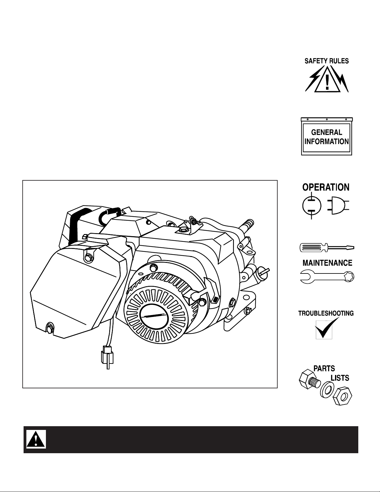
GENERAC®ENGINES
Overhead Valve
Industrial
Owner’s Manual
Manual No.A8927
Model No. GN - 320/360/410 (11/13/15 Horsepower)
TTHHIISS SSYYMMBBOOLL PPOOIINNTTSS OOUUTT IIMMPPOORRTTAANNTT SSAAFFEETTYY IINNSSTTRRUUCCTTIIOONNSS,, WWHHIICCHH,, IIFF NNOOTT FFOOLLLLOOWWEEDD,, CCOOUULLDD EENNDDAANNGGEERR
TTHHEE PPEERRSSOONNAALL SSAAFFEETTYY AANNDD//OORR PPRROOPPEERRTTYY OOFF YYOOUURRSSEELLFF AANNDD OOTTHHEERRSS.. RREEAADD AANNDD FFOOLLLLOOWW AALLLL
IINNSSTTRRUUCCTTIIOONNSS IINN TTHHEE MMAANNUUAALL BBEEFFOORREE AATTTTEEMMPPTTIINNGG TTOO OOPPEERRAATTEE TTHHIISS UUNNIITT..
Revision 0 (11/16/98) Printed in U.S.A.
Page 2
GGeenneerraacc GGNN--332200//336600//441100 EEnnggiinnee
RULES FOR SAFE OPER ATION
If you don’t understand any portion of this manual, contact
Generac for a demonstration of actual starting, operating and
servicing procedures.
Throughout this publication and on tags and decals affixed to
the generator, DANGER,WARNING and CAUTION blocks are
used to alert you to special instruction about a particular
operation that may be hazardous if performed incorrectly or
carelessly. Observe them carefully.
These safety warnings cannot eliminate the hazards that they
indicate. Strict compliance with the special instructions while
performing the service plus “common sense” are major
measures to prevent accidents.
The following definitions apply to DANGER, WARNING,
CAUTION and NOT E blocks found throughout the manual.
Study these RULES FOR SAFE OPERATION carefully before
operating or servicing this equipment. Become familiar with the
OWNER’S MANUAL and with the engine.The engine can
operate safely, efficiently and reliably only if it is properly
operated and maintained. Many accidents are caused by failing
to follow simple and fundamental rules or precautions.
Generac cannot possibly anticipate ever y possible circumstance
that might involve a hazard. The warnings in this manual and on
tags and decals affixed to the equipment, are therefore, not allinclusive.If you use a procedure, work method or operating
technique Generac does not specifically recommend, you must
satisfy yourself that it is safe for you and others.You must also
make sure the procedure, work method or operating technique
that you choose does not render the engine to be unsafe.
These safety symbols indicate the following:
DANGER: After this heading you can read handling,
installing, operating or servicing instructions that, if not
strictly complied with, will result in personal injury.
WARNING: After this heading you can read handling,
installing, operating or servicing instructions that, if not
strictly complied with, may result in personal injury.
CAUTION: After this heading you can read instructions for
handling, installing, operating or servicing the g enerator
that, if not strictly complied with, may result in damage to
equipment and/or property.
NOTE: After this heading you can read explanatory statements that
require special emphasis.
These symbols indicate the following:
Points out important safety infor mation and, if not followed, could
endanger personal safety and/or property of yourself and others.
P
otential explosion hazard.
DANGER: Do not tamper with the engine governed speed.
High operating speeds are dangerous and increase the
risk of personal injury or damage to the equipment.
Operating at low speeds with heavy load may shorten the
engine’s life.
BEFORE OP ERATING
• Gasoline is highly FLAMMABLE and its vapors are
EXPLOSIVE. Do not permit smoking, open flames, sparks or
heat in the area while handling gasoline. Avoid spilling
gasoline on a hot engine. Comply with all of the laws
regulating storage and handling of gasoline.
• Store gasoline and other fuels only in containers designed
and approved for the storage of such materials.
• Pressure can build up in the fuel tank. Loosen the fuel tank
slowly to relieve any pressure in the tank.
• Add gasoline and other fuels in a clean, well-ventilated area.
Wipe up any spilled gasoline immediately. If gasoline has
been spilled, let it dry completely before starting the engine.
Potential fire hazard.
Potential electrical shock hazard.
WWAARRNNIINNGG::
The engine exhaust from this product
contains chemicals known to the State
of California to cause cancer, birth
defects, or other reproductive harm.
— 2 —
Page 3

GGeenneerraacc GGNN--332200//336600//441100 EEnnggiinnee
• Do not overfill the fuel tank.Always allow room for fuel
expansion. If the tank is overfilled, the fuel can overflow onto
a hot engine and cause a FIRE or an EXPLOSION.
• Allow at least two (2) feet of clearance on all sides of the
engine, even while operating it outdoors, or you could damage
the engine.
• Thoroughly inspect the engine for loose or damaged parts
before each use.Do not use the engine until adjustments or
repairs are made.
• Check the oil level in the engine before each use.
• Inspect the engine periodically. Repair or replace all damaged
or defective parts immediately.
• Inspect fuel system frequently for leaks or damage.Repair or
replace any damaged or leaking component immediately.
Never attempt to change, alter or modify the engine fuel
system in any way that might affect safety or compliance with
applicable codes and standards.
WHILE OP ERATING
• This engine was designed and manufactured for specific
applications. Do not attempt to modify the equipment or
use it for any application for which it was not designed.
• Engine exhaust gases contain DEADLY carbon monoxide
gas.This dangerous gas, if breathed in sufficient
concentrations, can cause unconsciousness or even death.
Operate this equipment only in the open air where adequate
ventilation is available.
• Do not insert any object through the cooling slots of the
engine.You could damage the equipment or injure yourself.
• Do not operate the engine faster than the speed necessary to
operate the equipment. Do not run the engine at high speed
when not operating the equipment.
• This engine requires an adequate flow of cooling air for its
continued proper operation. Never operate the equipment
inside any room or enclosure where the free flow of cooling air
into and out of the equipment might be obstructed. Without
sufficient cooling air flow, the engine quickly overheats,
damaging the engine or nearby property.
• Do not smoke around the engine.Wipe up any fuel or oil spills
immediately. Never leave oily or fuel soaked rags around the
engine. Keep the area around the engine clean and free of
debris.
• Keep hands, feet, clothing, etc., away from moving parts of
this engine.
• Never operate the engine (a) in the rain; (b) in any enclosed
compartment; (c) if the engine speed changes; (d) if the
engine sparks; (e) if flame or smoke is obser ved while the
engine is running.
• Never wor k on this engine or handle any electrical device
while standing in water, while barefoot, or while hands or feet
are wet. DANGEROUS ELECTRIC SHOCK will result.
— 3 —
Page 4
GGeenneerraacc GGNN--332200//336600//441100 EEnnggiinnee
This engine meets the 1998 and later California emissions
regulations.To ensure that your engine continues to meet
these regulations, refer to the following information and
instructions in this owner’s manual.
SERVICE IN FORMATION
Service on this engine within and after the warranty
period can be performed by any authorized service
dealer.Ser vice technicians are factory trained and
capable of handling all service needs.
When contacting an authorized service dealer or the
factory about parts and ser vice, always supply the
complete model number and serial number of your unit as
given on its data plate decal.
The warranty and replacement parts for this engine are
included in the owner’s manual.
When ordering engine components, you must provide the
authorized service dealer with the engine identification number,
which is located on the engine identification decal. See the
illustration below for the location of the decal.
TABLE OF CONTENTS
RULES FOR SAFE OPERATION ..........................................2-3
GENERAL INFORMATION ....................................................4-5
Service Information ..................................................................4
Engine Identification Decal Location ........................................4
Oil and Fuel Information............................................................5
OPERATION ..........................................................................6-7
Before Starting the Engine........................................................6
Starting the Engine ................................................................6-7
Stopping the Engine..................................................................7
Low Pressure Shutdown System ..............................................7
MAINTENANCE ..................................................................8-13
General Maintenance Recommendations ................................8
Service and Adjustments ....................................................8-10
Carburetor Adjustments ..........................................................11
Checking/Adjusting Valve to Rocker Ar m Clearance ..............11
Retorquing Head Bolts ......................................................11-12
Maintenance Schedule............................................................12
Storage Instructions ................................................................13
Specifications ..........................................................................13
Generac Corporation
Eng. Identif. No. XXXXXX
Displacement XXXXXX
PARTS LISTS & EXPLODED VIEWS ..............................14-21
WARRANTIES ..................................................................22-24
California Emission Control Warranty Statement ....................22
Emission Control System Warranty ........................................23
Generac Engine Warranty ........................................Back Cover
Decal
— 4 —
Page 5
GGeenneerraacc GGNN-- 332200//336600//441100 EEnnggiinnee
OIL AN D FU EL I NFOR MATION
NOTE: BE SURE TO READ THESE INSTRUCTIONS
CAREFULLY BEFORE ATTEMPTING TO START OR
OPERATE THIS EQUIPMENT. Using old or improper oil or
fuel can cause engine damage.
CAUTION: Any attempt to crank or start the engine
before it has been properly serviced with the
recommended oil may result in engine damage.
RECOMMENDED OI L T YP E
Using the proper type and weight of oil in the crankcase is
extremely important. Check the oil before each use and change
the oil regularly. Failure to use the correct oil, or using dir ty oil,
can cause premature engine wear and failure.
The recommended oils include the following:
• During summer months: SAE 10W-30,
• During winter months: SAE 5W-20 or 5W-30. DO NOT USE
SAE 10W-40.
The crankcase oil capacity is about 1500 ml (51 oz.) with the oil
filter.Without the filter, the oil capacity is 1350ml (46 oz.). Use no
special additives.
RECOMMENDED FUEL TYPE
Use clean, fresh, regular UNLEADED gasoline with this engine.
CAUTION: Do not overfill the fuel tank. Always allow
room for fuel expansion.
WARNING: NEVER FILL THE FUEL TANK INDOORS. OR
WHEN THE ENGINE IS RUNNING OR HOT. DO NOT
LIGHT A CIGARETTE OR SMOKE WHEN FILLING THE
FUEL T ANK.
— 5 —
Page 6
GGeenneerraacc GGNN--332200//336600//441100 EEnnggiinnee
OPER ATION AND MAI NTENANCE
It is the owner’s/operator's responsibility to perform all safety
checks; to make sure that all maintenance for safe operation is
performed promptly; and to have the engine checked by an
authorized dealer periodically. Normal maintenance service and
replacement of parts are the responsibility of the owner/operator
and, as such, are not considered defects in materials or
workmanship within the terms of the warranty. Individual
operating habits and usage contribute to the need for
maintenance service.
Proper maintenance and care of your engine assures a minimum
number of problems and keeps your operating expenses at a
minimum. See your authorized dealer/distributor for service aids
and accessories.
BEFOR E STARTI NG TH E ENGI NE
Perfor m the following tasks before trying to start the engine:
ADDING ENGINE OIL
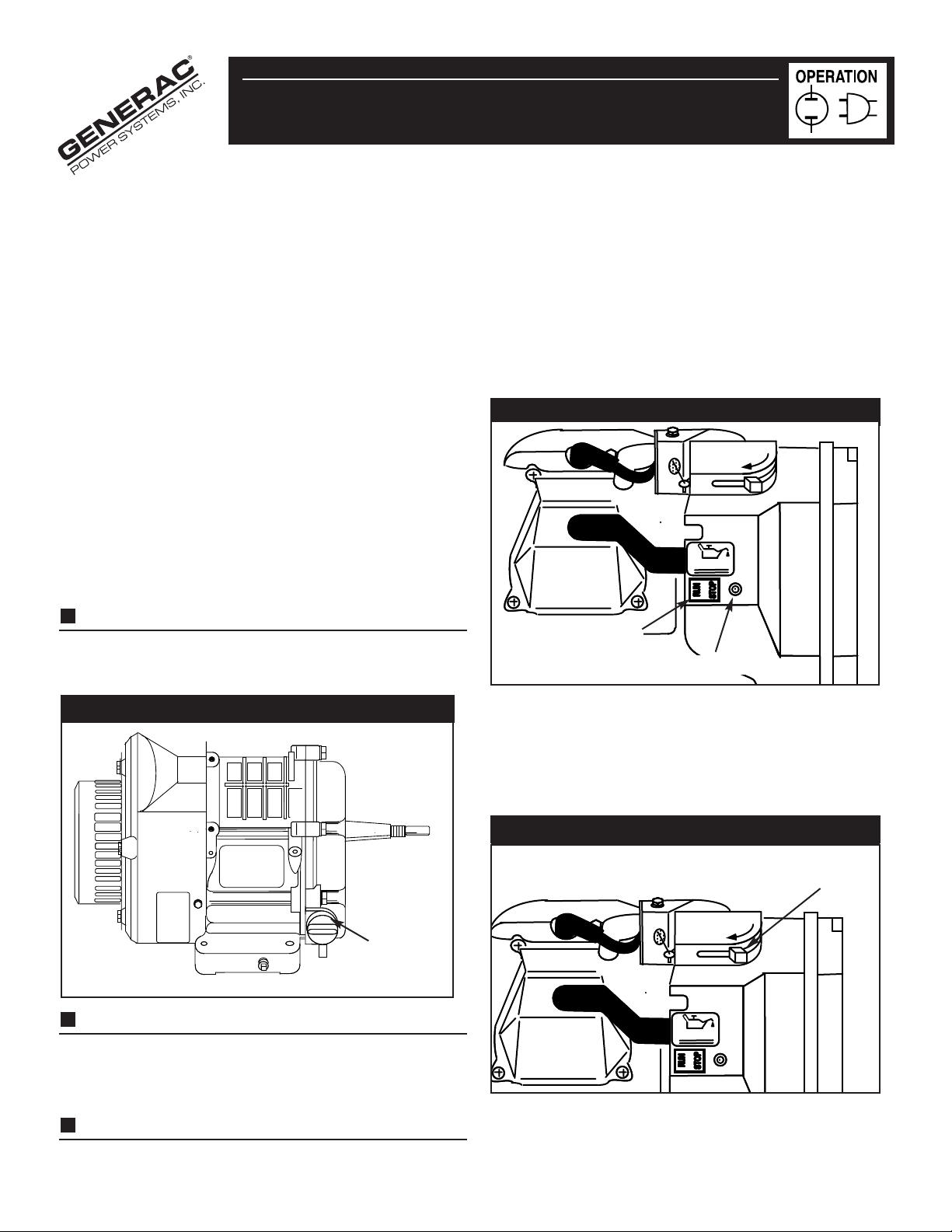
1. Remove the yellow oil fill cap from the crankcase (Figure 1).
2. Add engine oil until the oil level is to the point of overflowing.
STARTI NG THE ENGI N E
1. Open the fuel shut-off valve, if so equipped.
2. If your unit is equipped with the IDLE/CONTROL feature,
locate the IDLE/CONTROL ON/OFF SWITCH on the control
panel, and set it to the OFF (O) position.
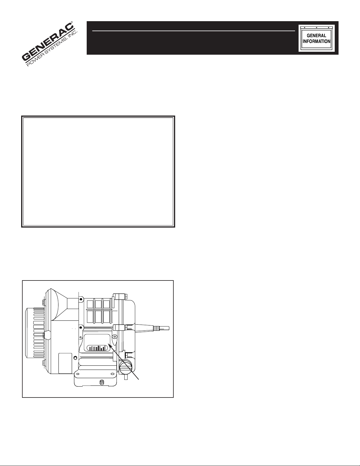
3. Locate the RUN/STOP SWITCH (Figure 2) next to the
engine cylinder head and push it to RUN.
Figure 2 — RUN/STOP SWITCH
CHOKE
OHVI
RUN / STOP SWITCH
LOW OIL LIGHT
LOWOIL
Figure 1 — Oil Fill Cap
Oil Fill
Cap
CHECKING ENGINE OIL
1. Check the engine oil level before starting the engine each
time after the initial start. If the oil level is below the point of
overflowing, fill to the proper level.
ADDING FUEL
1. Fill the fuel tank using clean, fresh UNLEADED gasoline.
If your engine is equipped with a choke, use the
following instructions:
1. Place the choke lever in the FULL CHOKE POSITION
(Figure 3) by sliding it to the left (towards the valve cover),
in the direction indicated by the arrow.
Figure 3 — Choke Position
CHOKE LEVER
CHOKE
OHVI
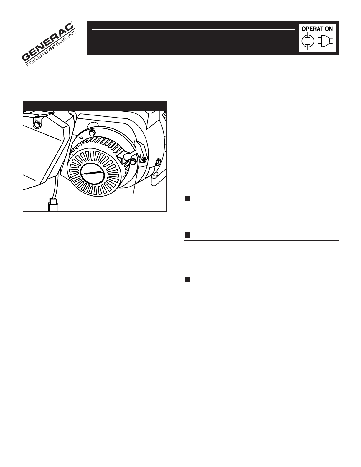
2. Grasp the recoil handle (Figure 4) and pull it slowly until you
feel slight resistance, then PULL QUICKLY.
LOWOIL
— 6 —
Page 7
GGeenneerraacc GGNN--119900//220000 EEnnggiinnee
A If the engine F AILS TO START , go to Step 3.
B. If the engine STARTS, go to Step 4.
Figure 4 — Recoil Handle
Recoil Handle
3. Move the choke lever to the HALF CHOKE POSITION,
and pull the recoil handle (Figure 4) two (2) times.
• If the engine STILL F AILS T O ST ART, repeat
Steps 1-3.
4. Move the choke lever to the RUN POSITION by sliding it
to the right (away from the valve cover and under the
arrow).
STOPPI NG TH E ENGI NE
1. Remove the load on the engine, and let it run for 30
seconds.
2. Turn off the engine by moving the RUN/STOP SWITCH to
the STOP position.
3. Close the fuel shut-off valve, if so equipped.
LOW PR ESSURE SH UTDOWN SYSTE M
The engine is equipped with a low oil pressure sensor that shuts
down the engine automatically when the oil pressure drops below 8
psi ). If the engine shuts down by itself and the fuel tank has
enough gasoline, check the engine oil level.
INITIAL STARTU P
A delay built in the shutdown system allows oil pressure to build
during starting. The delay allows the engine to run for about 10
seconds before sensing oil pressure.
SENSING LOW PRESSURE
If the system senses low oil pressure during operation, the
engine shuts down. As the system shuts down, the low oil light
comes ON (see Figure 2, page 6). H ow ever, once the engine
stops rotating, this light will go OFF.
5. Allow the engine to warm up for two (2) minutes before
using the equipment.
RESTARTI NG TH E ENGI NE
If you try to restart the engine within (five) 5 seconds after it
shuts down, the engine may NOT star t. The system needs 5 to
10 seconds to reset.
NOTE: If you do restar t engine after a shutdown and have not
corrected the low oil pressure, the engine will run for
about 10 seconds as described above, and then it will stop.
— 7 —
Page 8
GGeenneerraacc GGNN--332200//336600//441100 EEnnggiinnee
GENER AL MAINTENANCE
2. When the oil is drained, install and tighten the oil drain
RECOMMEN DATIONS
3. If your engine is equipped with an oil filter, use the
The owner/operator is responsible for making sure that all per iodic
maintenance tasks are completed on a timely basis; that all
discrepancies are corrected; and that the equipment is kept clean
and properly stored. Never operate a damaged or defective
engine.
CAUTION: Disconnect the spark plug wire from the spark
plug, and place the wire where it cannot come in contact
with the spark plug before working on this engine.
CHECKING THE OI L LEVEL
See the BEFORE STARTING THE ENGINE section on page 6 for
information on checking the oil level. The oil level should be
checked before each use, or at least every eight (8) hours of
operation. Keep the oil level maintained.
CHANGING THE OI L AN D OIL F I LTER
Your engine may be equipped with an oil filter. Change the oil and
filter after the first eight (8) hours of operation. Change the oil
and oil filter (if so equipped) every 50 hours thereafter. If you are
using this engine under dirty or dusty conditions, or in extremely
hot weather, change the oil more often.
Use the following instructions to change the oil while the engine is
still warm:
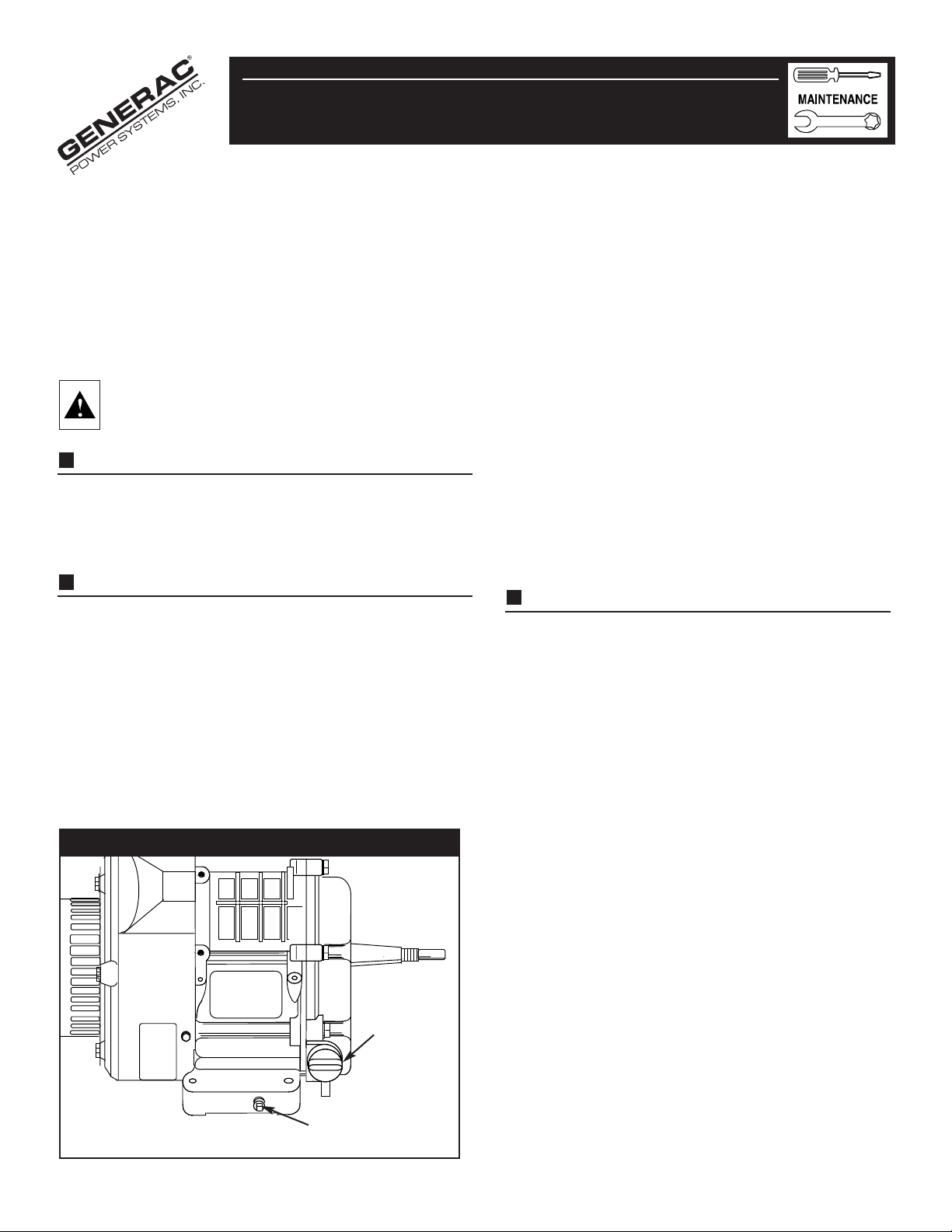
1. Clean the area around the oil drain plug, remove the plug and
drain the oil completely into a suitable container (Figure 5).
4. Remove the oil fill plug and insert a clean funnel into the
5. When the crankcase is filled to the proper level, install
Your equipment’s air cleaner is one of the most important
areas to maintain.This engine will not r un properly and may
get damaged if it is run with a dirty air cleaner system.
Clean or replace the paper air filter (Figure 6) every 50
hours of operation or once a year, whichever comes first.
Clean or replace the filter more often if the engine is operated
under dusty or dirty conditions. Clean the foam pre-filter
every 25 hours of operation, or sooner under dusty or dirty
conditions.
plug.
following instructions:
A. Place a suitable container beneath the oil filter and
turn the filter counterclockwise to remove the filter.
B. Coat the gasket of a new filter with engine oil. Turn
the new filter clockwise until the gasket contacts the
filter adapter, then tighten an additional 3/4 turn.
plug opening. Fill the crankcase with the recommended
oil until the oil level is at point of overflowing. Approximately 1350ml (46 oz.) are required without an oil filter;
1500ml (51 oz.) with an oil filter.POUR SLOWLY.
and tighten the oil fill plug.
SERVICING THE AI R CLEAN ER
.
Figure 5 — Oil Filter and Drain Plug
Oil Filter
Drain Plug
— 8 —
Page 9

GGeenneerraacc GGNN--332200//336600//441100 EEnnggiinnee
CAUTION: Never run this equipment without the complete
air cleaner system installed on the engine.This could result
in premature wear to the engine.
Use the following instructions to clean or replace the
air cleaner components.
1. Loosen the two screws on the air cleaner cover. Remove the
air cleaner cover (Figure 6).
Figure 6 — Removing the Air Cleaner Cover
Foam
Pre-Filter may
stick to cover
CHOKE
3. To clean or replace the foam pre-filter:
A. Wash the pre-filter in soapy water.
B. Squeeze the pre-filter dry with a clean cloth. DO
NOT TWIST .
NOTE: If the pre-filter is still dirty after washing and drying it,
replace it with a new one.
C. Apply enough clean engine oil to saturate the pre-
filter.
D. Wrap the pre-filter in a clean dry cloth and squeeze
out the excess oil. DO NOT TWIST. Set the pre-filter
aside.
4. To clean or replace the paper air filter:
A. Clean the air filter by tapping it gently on a solid
surface.
NOTE: If the filter is too dirty, replace it with a new one.
Dispose of the old filter properly.
5. Clean the air cleaner cover.
6. Insert the pre-filter into the cover, then the paper air
filter (see Figure 7).
2. Remove the paper air filter and the foam pre-filter from the
air cleaner cover (Figure 7).
Figure 7 — Air Cleaner Components
Foam
Pre-Filter
CHOKE
Paper
Filter
7. Reinstall the air cleaner cover and tighten the two (2)
screws (see Figure 6).
REPL ACING TH E SPARK PLUG
Use a Champion RC12YC spark plug or equivalent.The
correct air gap is 0.76mm (0.030 in.). Remove the plug ever y
100 hours of operation or once each year, whichever comes
first.This will help your engine to star t easier and r un better.
1. Stop the engine and pull the spark plug wire off of the
spark plug.
2. Clean around the spark plug and remove it from the
cylinder head.
— 9 —
Page 10

Generac GN-320/360/410 Engine
3. Set the spark plug gap (Figure 8) to 0.76mm (0.030 in.).
Install a correctly gapped spark plug into the cylinder head.
Figure 8 — Setting Spark Plug Gap
SET PLUG GAP AT 0.76 mm
(0.030 inch)
Figure 9 — Removing Heat Shield
Spark
Arrestor
Screen
83083
CLEANING TH E SPARK ARRESTOR
SCREEN
The engine exhaust muffler has a spark arrestor screen. Inspect
and clean the screen every 100 hours of operation or once
each year, whichever comes first.
NOTE: If you use your engine on any forest-covered, brush-
covered or grass-covered unimproved land, it must
have a spark arrestor. The spark arrestor must be
maintained in good condition by the owner/operator.
Clean and inspect the spark arrestor screen as follows:
Inspect the screen and replace if it is torn, perforated or otherwise
damaged (see Steps 1-4 below).DO NOT USE a def ectiv e screen.If
the screen is not damaged, clean it with a commercial solvent.
If the spark arrestor is found to be damaged or defective, replace it
as follows:
1. Remove the four (4) screws that connect the heat shield to
the muffler (Figure 9).
2. Remove the four (4) screws that attach the spark arrestor
screen (Figure 9).
3. Replace damaged screen with new screen (Part No.83083).
4. Reattach the screen and the heat shield with the four (4)
screws. Resintall the heat shield to the muffler with the four
(4) screws.
SERVICE AND ADJ USTMENTS
Your engine r uns at a constant speed. This constant operating
speed is maintained by a mechanical, flyweight type, fixed
speed governor.DO NOT try to adjust the governed speed
setting for the following reasons:
• Operating the engine at high engine speeds is dangerous and
• Operating the engine at low engine speeds with heavy loads may
Heat Shield
ENGINE SPEED
CAUTION: The engine speed was properly adjusted at the
factory and should require no additional adjustment. Do
not attempt to change engine speed. If you believe the
engine is running too fast or too slow, take your engine to
an authorized service center for repair and adjustment.
CHANGING THE ENGINE GOVERNED SPEED WILL
VOID THE ENGINE W ARRANTY.
increases the risk of personal injury or damage to the
equipment.
shorten the engine’s life.
— 10 —
Page 11

Tighten Jam Nut to
65-85 inch-pounds
Allen Wrench
Feeler Gauge
Loosen Jam Nut,
GGeenneerraacc GGNN--332200//336600//441100 EEnnggiinnee
OHVI
LOW
OI
CARBURETOR ADJUSTMENTS
The carburetor of your engine is pre-set at the factor y.The
carburetor should not be tampered with because this will VOID
THE EMISSION CONTROL SYSTEM WARRANTY.If you
experience problems and your engine is used at an altitude in
excess of 5000 feet, contact the nearest authorized dealer
regarding high altitude setting changes.
CHECKING/ADJ USTING VALVE TO
ROCKER ARM CLEAR ANCE
Every 50 hours of operation, remove the rocker cover and
check the valve to rocker arm clearance.
When adjusting the clearance, the engine should be at room
temperature, and the piston should be at Top Dead Center
(TDC) of its compression stroke (both valves are closed). The
correct clearance is 0.05-0.1mm (0.002-0.004 in.). Check and
adjust the valve to rocker arm clearance as follows:
1. Remove the four (4) screws from the rocker cover
(Figure 10).
2. Remove the rocker cover and rocker cover gasket.
Figure 10 —Removing the Valve Cover
3. Loosen the rocker arm jam nut. Using an allen wrench to turn
the pivot ball stud, check the clearance between the rocker
arm and the valve stem with a flat feeler gauge (Figure 11).
Figure 11 — Adjusting Valve to Rocker Arm Clearance
4. When the valve clearance is correct, hold the pivot ball stud
with the allen wrench and tighten the rocker arm jam nut.
Torque the jam nut to 7.15-9.35 N-m (65-85 in-lb). After
tightening the jam nut, recheck the valve clearance to make
sure it did not change (see Figure 11).
5. Reinstall the rocker cover gasket, rocker cover and
the four (4) screws (see Figure 10).
— 11 —
Page 12

GGeenneerraacc GGNN--332200//336600//441100 EEnnggiinnee
C
B
D
A
RETORQUI NG TH E H EAD BOLTS
After the first 50 hours of operation, retorque the head bolts.
NOTE: Only perform this adjustment after the first 50 hours of
operation.The head bolts will need no fur ther adjustment.
1. Remove the four (4) screws from the rocker cover
(see Figure 10).
2. Remove the rocker cover and rocker cover gasket.
3. Torque the bolts to 6.9 kg-m. (44 ft-lb).
4. Torque the bolts in the following sequence: A, B, C, D, (star
pattern). See Figure 12.
Figure 12 — Tightening Sequence
MAINTENANCE SCHEDULE
Every 8 Hours or 25 Hours or Every 50 Hours or Every 100 Hours or Every
MAINTENANCE OPERATION or Daily Season Season Season
Check Oil Level X
Change Oil See Note 1
Change Oil Filter (if so equipped) See Note 1
Service Air Filter Foam Pre-Filter Paper Filter (Note 2)
Replace or Clean Spark Plug X
Clean Spark Arrestor Screen X
Adjust Valv e Clearance X
Retorque Head Bolts See Note 3
NOTE 1: Change oil and filter after first 8 hours of operation and then every 50 hours thereafter. Change sooner when operating under heavy load or
in dusty or dirty environment or in high ambient temperature.
NOTE 2: Clean more often when operating under dirty or dusty conditions.
NOTE 3: Perform this task ONLY after first 50 hours of operation. Head bolts will NOT need further retorquing.
— 12 —
Page 13

GGeenneerraacc GGNN--332200//336600//441100 EEnnggiinnee
STORAGE INSTRUCTIONS
This engine should be started at least once a week and run for at
least 30 minutes. If this cannot be done and the equipment must
be stored for more than 30 days, use the following guidelines to
prepare it for storage.
WARNING: Never store the engine with the fuel in the tank
indoors or in an enclosed, poorly ventilated areas, where
fumes can reach an open flame spark or pilot light as on a
furnace, water heater, or clothes dryer.
1. Run the engine for about five (5) minutes to war m it.
NOTE: Alcohol-blended fuel, or “gasohol”, attracts moisture which
can lead to the separation and formation of acids during
storage.This acidic gas can damage internal engine parts.
Methanol, ethanol and grain alcohol all are forms of
gasohol. If you did use “gasohol,” drain the fuel tank, then
run the engine until it stops from lack of fuel.
WARNING: Drain the fuel into approved container outdoors,
away from open flame. Be sure the engine is cool.
OTHER STOR AGE TIPS
1. Do not store gasoline from one season to another.
2. Replace the gasoline can if it starts to rust. Rust and/or dirt
in a gasoline can cause problems when you use that fuel
with this equipment.
3. Store the equipment in a clean and dry area.
SPECIF ICATIONS
Model GN-320 GN-360 GN-410
Bore 80mm 85mm 90mm
Stroke 64mm 64mm 64mm
Valve Clearance 0.05–0.10mm 0.05–0.10mm 0.05–0.10mm
Displacement 321cc 363cc 407cc
Maximum Tilt Angle
While Operating 15° 15° 15°
Oil Capacity with Oil 1500ml 1500ml 1500ml
Filter (51 oz.) (51 oz.) (51 oz.)
Oil Capacity without Oil 1350 ml 1350 ml 1350 ml
Filter (46 oz.) (46 oz.) (46 oz.)
NOTE: Using a fuel additive such as STA-BIL® fuel stabilizer, or an
equivalent, will prevent gum deposits from forming in the
engine’s fuel system.
2. While the engine is still warm, drain the oil from the
crankcase. Refill with it with fresh oil. See BEFORE
STARTING ENGINE on Page 6 for oil recommendations.
3. Remove spark plug and pour about 1/2 ounce (15ml) of
engine oil into the cylinder. Crank slowly to distribute oil.
CAUTION: Avoid spray from the spark plug hole when
cranking the engine slowly.
4. Install the spark plug. Do not connect the spark plug wire.
5. Clean the dirt, oil and grease from the cylinder, cylinder head,
fins, blower housing, rotating screen and muffler area.
6. Close the fuel shut-off valve.
— 13 —
Page 14

3C
— 14 —
4C
EEXXPPLLOODDEEDD VVIIEEWW —— LLOONNGG BBLLOOCCKK ((GGNN--332200//336600//441100))
Generac GN-320/360/410 Engine
21A
21B
10C
Page 15

GGeenneerraacc GGNN--332200//336600//441100 EEnnggiinnee
RREEPPAAIIRR PPAARRTTSS LLIISSTT —— LLOONNGG BBLLOOCCKK ((GGNN--332200//336600//441100))
ITEM PART NO. QTY. DESCRIPTION
1 71978 1 Connecting Rod With Cap
and Bolt
2 71980 1 Piston Pin
3A 89291 1 Piston Ring Set 80 MM (320)
3B 71977 1 Piston Ring Set 85 MM (360)
3C 21533 1 Piston Ring Set 90 MM (410)
4A 89217 1 Piston 80 MM (320)
4B 76339 1 Piston (360)
4C 96699 1 Piston (410)
5 71983 2 Piston Pin Retainer
6A 78666A 1 Crankshaft Assembly With
Gears (Small Taper)
6B 76378A 1 Crankshaft Assembly With
Gears (Straight Shaft)
7 A7628 1 Governor Arm
8 78658 1 Governor Arm “R” Pin
9 78659 2 Governor Arm Washer
10A 88261D 1 Crankcase H.S. W/Taper Plugs
(320)
10B 88261C 1 Crankcase H.S. W/Taper Plugs
(360)
10C 88261E 1 Crankcase H.S. W/Taper Plugs
(410)
12 72655 2 Crankshaft Seal
13 A8930 1 Gov. Gear Assembly
14 78645 1 Governor Retainer
(“C” Ring)
15 A7811 1 Governor Spool
19 A7081 1 Camshaft Assembly
20 76701 1 Crankcase Gasket
21A 21713A 1 Cylinder Head Gasket
(320-360)
21B 21713B 1 Cylinder Head Gasket (410)
22 78691 1 Oil Pressure Reliefcover
23 A5771 1 Pressure Relief Spring
24 A5776 1 Pressure Relief Ball
25 76361 1 Thrust Washer
26 A8898B 1 Gear Cover
27 86514 2 Valve Spring Retainer
28 91308 2 Valve Spring
ITEM PART NO. QTY. DESCRIPTION
29 86025 1 Gerotor Set
30 84430 1 Balancer
31 21714 1 Cylinder Head With Valve
Seats & Guides
32 86516 1 Exhaust Valve
33 86517 1 Intake Valve
34 88396B 2 Push Rod
35 83897 2 Tappet
36 77158 1 Oil Pick-Up Assembly
37 71987 1 Rocker Cover Gasket
38 72694 2 Pivot Ball Stud
39 83907 2 Rocker Arm
40 72696 2 Jam Nut (Rocker Arm)
41 78694 1 Push Rod Guide Plate
42 21742 4 M10-1.5 x 10⁵ Head Bolt
43 83938 1 Rocker Cover Breather
Assembly
44 76329 1 Oil Fill Plug
46 86254 1 O-Ring 17.8 I.D. x 2.4 THK.
47 26925 2 3/8" NPT Pipe Plug
48 74908 1 M5-0.8 x 8MM Screw
(Thread Forming)
50 86515 4 Valve Spring Keeper
51 78606 4 M6-1 x 12MM Pan Head
Screw & Lockwasher
52 A1442 8 Hex Head Flange Bolt
M8-1.25 x 42MM
53 78672 1 Valve Stem Seal
54 89673 2 Valve Spring Washer
N/A 21947C 1 Long Block Assm. (320cc
w/item 6A
N/A 21948C 1 Long Block Assm. (360cc
w/item 6A
N/A 21949C 1 Long Block Assm. (360cc
w/item 6B
N/A A1044A 1 Long Block Assm. (410cc
w/item 6A
N/A A6497A 1 Long Block Assm. (410cc
w/item 6B
— 15 —
Page 16

GGeenneerraacc GGNN--332200//336600//441100 EEnnggiinnee
EEXXPPLLOODDEEDD VVIIEEWW —— AAIIRR CCLLEEAANNEERR AANNDD CCAARRBBUURREETTOORR
43A
43B
43C
— 16 —
Page 17

GGeenneerraacc GGNN--332200//336600//441100 EEnnggiinnee
AAIIRR CCLLEEAANNEERR AANNDD CCAARRBBUURREETTOORR
ITEM DESCRIPTION PART NO. QTY. ITEM DESCRIPTION PART NO. QTY.
31 Breather Hose 72745 1
32 Manifold Head Gasket 91039 1
33 M6 x 20 SHCS 40945 2
34 Carburetor Bolt 81647 2
35 M6 x 12 HHCS 66476 2
36 K Adapter 91028 1
37 M6 Lock Washer 22097 3
38 M6 Hex Nut 49813 2
39 Carburetor/Air Box 90970 1
Gasket
40 M6 Ribbed Lock- 93873 2
washer
41 Spitback Plate 91204 1
42 Carburetor/Manifold 89228 1
Gasket
43A 320 Nikki Carburetor 93302A 1
43B 360 Nikki Carburetor 91187A 1
43C 410 Nikki Carburetor A4600 1
44 Air Cleaner Base 73108A 1
45 M6 Flatwasher 49811 4
46 #8 x 3/8" Plastite 59635 1
Screw
47 Air Filter 73111 1
48 Precleaner 81646 1
49 Choke Knob 83504 1
50 M6 x 16 HHCS 47411 2
51 Bracket Air Box 90827 1
60 1/4” ID Hose 30340 12”
61 Hose Clamp 48031C 1
— 17 —
Page 18

GGeenneerraacc GGNN--332200//336600//441100 EEnnggiinnee
EEXXPPLLOODDEEDD VVIIEEWW —— GGAASS TTAANNKK MMOOUUNNTTIINNGG HHAARRDDWWAARREE
ITEM PART # QTY. DESCRIPTION
22 40976 2 SHCS M8-1.25 X 20
26 22129 2 Lock Washer M8
94 B2348 1 Tank Cradle
95 52858 2 M8 Lock Nut
96 59012 2 M8 X 20 FLHCS
97 96083 1 Front Tank Bracket
98 96084 1 Rear Tank Bracket
99 89263 1 Dipstick ASM
100 A6558 1 Oil Fill/Check Tube
— 18 —
Page 19

GGeenneerraacc GGNN--332200//336600//441100 EEnnggiinnee
EEXXPPLLOODDEEDD VVIIEEWW —— OOIILL FFIILLTTEERR AANNDD OOPPTTIIOONNAALL OOIILL FFIILLLL TTUUBBEE
ITEM PART # QTY. DESCRIPTION
2 86999 1 Oil Filter Gasket
3A 72709 1 Oil Blockoff
3B 94683 1 Oil Filter Adapter
4 49821 2 M8 X 30 SHCS
5 99236 1 Oil Press Switch
6 70185 1 Oil Filter
— 19 —
Page 20

GGeenneerraacc GGNN--332200//336600//441100 EEnnggiinnee
EEXXPPLLOODDEEDD VVIIEEWW —— LLOOWW OOIILL SSHHUUTTDDOOWWNN AANNDD GGOOVVEERRNNOORR
ITEM PART # QTY. DESCRIPTION
7 78653 1 Run/Stop Switch
8 85272 1 LED Assembly
9 93104 1 L.O.S. Decal
10 93611 1 Black Sleeving
12 84329 1 3 Pin Male HSG
13 92981 1 Wire Assembly
14 22097 2 M6 Lockwasher
15 92079 2 M6 X 30 Taptite
16 84542 1 Ignition Coil
18 87221B 1 L.O.S. Module
20 72347 1 Sparkplug
ITEM PART # QTY. DESCRIPTION
21 72734 1 Governor Lever
23 83502 1 Adjust Screw
24 83512 2 M8 X 15 Taptite
25 73100 1 60Hz Gov. Spring
27 83503 1 M5 Lock Nut
28 73101 1 Governor Brkt.
29 72735 1 Governor Rod
30 72789 1 Anti-Lash Spring
101 83782 1 Idle Coil ASM
102 66311 1 M8 — 1.25 Jam Nut
— 20 —
Page 21

GGeenneerraacc GGNN--332200//336600//441100 EEnnggiinnee
EEXXPPLLOODDEEDD VVIIEEWW —— SSTTEEPPPPEERR MMOOTTOORR,, FFLLYYWWHHEEEELL,, RREECCOOIILL SSTTAARRTTEERR
ITEM PART # QTY. DESCRIPTION
17 21544 1 Starter Motor Assm.
22 40976 2 SHCS M8 — 1.25 X 20
26 22129 2 Lock Washer M8
78 82774 1 Woodruff Key
79A SRV77147A 1 360 Flywheel
79B SRV91222B 1 320/360 Flywheel Ring Gear
79C SRV91222C 1 410 Flywheel Ring Gear
79D SRV21745G 1 410 Flywheel
80 67198N 1 Conical Washer
— 21 —
ITEM PART # QTY. DESCRIPTION
81 67890 1 M20 Hex Nut
82 88433 1 Top Wrapper
83 45756 7 M6 X 10 Taptite
84 78609 2 Cover Bolts
85 73104B 1 Air Box Cover
86 92437 1 Blower Housing
87 88434 1 Lower Wrapper
88 66476 4 M6 X 12 HHCS
89 96195 1 Recoil Assembly
90 96196 1 Recoil Cup
91A 73116C 1 Backplate
91B 73116A 1 Backplate, E. SRT
92 81668 5 M6 X 10 HHCS
93 B2160 1 Rubber Spacer
Page 22

GGeenneerraacc GGNN--332200//336600//441100 EEnnggiinnee
CALIFORNIA EMISSION CONTROL WARRANTY STATEMENT
YOUR WARRANTY RIGHTS AND OBLIGATIONS
The California Air Resources Board ("CARB") and Generac Corporation are pleased to explain the Emission Control System
Warranty on your new utility or lawn and garden equipment engine. In California, new utility and lawn and garden
equipment engines must be designed, built and equipped to meet the State's stringent anti-smog standards. Generac
Corporation will warrant the emission control system on your utility or lawn and garden equipment for the periods of time
listed below provided there has been no abuse, neglect, unapproved modification, or improper maintenance of your utility or
lawn and garden equipment engine.
Your emission control system may include parts such as the carburetor, ignition system and exhaust system. Also included may
be the compression release system and other emission-related assemblies.
Where a warrantable condition exists, Generac Corporation will repair your utility or lawn and garden equipment engine at
no cost to you for diagnosis, parts and labor.
MANUFACTURER'S EMISSION CONTROL SYSTEM WARRANTY COVERAGE:
Emissions control systems on 1995 and later model year utility and lawn and garden equipment engines are warranted for two
years as hereinafter noted. If, during such warranty period, any emission-related part on your engine is defective in materials
or workmanship, the part will be repaired or replaced by Generac Corporation.
OWNER'S WARRANTY RESPONSIBILITIES:
As the utility or lawn and garden equipment engine owner, you are responsible for the performance of the required
maintenance listed in your owners manual. Generac Corporation recommends that you retain all receipts covering
maintenance on your utility or lawn and garden equipment engine, but Generac Corporation will not deny warranty solely
due to the lack of receipts or for your failure to provide written evidence of the performance of all scheduled maintenance.
As the utility or lawn and garden equipment engine owner, you should, however, be aware that Generac Corporation may
deny you warranty coverage if your utility or lawn and garden equipment engine or a part thereof has failed due to abuse,
neglect , improper maintenance or unapproved modifications.
You are responsible for presenting your utility or lawn and garden equipment engine to a Generac Corporation Authorized
Service Outlet as soon as a problem exists. The warranty repairs should be completed in a reasonable amount of time, not to
exceed 30 days.
Warranty service can be arranged by contacting either a Generac Corporation Authorized Service Outlet or by contacting
Generac Corporation at:
GENERAC CORPORATION PH: (414) 544-4811
P.O. BOX 8 FAX: (414) 544-0179
WAUKESHA, WI 53187
IMPORTANT NOTE: This warranty statement explains your rights and obligations under the Emission Control System
Warranty ("ECS Warranty") which is provided to you by Generac Corporation pursuant to California law. See also the Generac
Corporation Limited Warranties for Generac Corporation which is enclosed herewith on a separate sheet and also is provided
to you by Generac Corporation. The ECS Warranty applies only to the emission control system of your new engine. To the
extent that there is any conflict in terms between the ECS Warranty and the Generac Corporation Warranty, the ECS Warranty
shall apply except in any circumstances in which the Generac Corporation Warranty may provide a longer warranty period.
Both the ECS Warranty and the Generac Corporation Warranty describe important rights and obligations with respect to your
new engine.
Warranty service can only be performed by a Generac Corporation Authorized Service Outlet. At the time of requesting
warranty service, evidence must be presented of the date of the sale to the original purchaser. The purchaser shall pay any
charges for making service calls and/or for transporting the products to and from the place where the inspection and/or
warranty work is performed. The purchaser shall be responsible for any damage or loss incurred in connection with the
transportation of any engine or any part(s) thereof submitted for inspection and/or warranty work.
IF YOU HAVE ANY QUESTIONS REGARDING YOUR WARRANTY RIGHTS AND RESPONSIBILITIES, YOU SHOULD CONTACT
GENERAC CORPORATION AT 1-800-222-3136.
— 22 —
Page 23

GGeenneerraacc GGNN--332200//336600//441100 EEnnggiinnee
EMISSION CONTROL SYSTEM WARRANTY
Emission Control System Warranty ("ECS Warranty") for 1995 and Later Model Year Utility and Lawn and Garden Equipment Engines:
A. Applicability: This warranty shall apply to 1995 and later model year utility and lawn and garden equipment engines. The ECS Warranty
Period ("ECS Warranty Period") shall begin on the date the new engine or equipment is delivered to its original, end-use purchaser and shall
begin on the date the new engine or equipment is delivered to its original, end-use purchaser and shall continue for 24 consecutive months
thereafter.
B. General Emissions Warranty Coverage: Generac Corporation warrants to the original, end-use purchaser of the new engine or equipment
and to each subsequent purchaser that each of its utility and lawn and garden equipment engines is:
1. Designed, built and equipped so as to conform with all applicable regulations adopted by the Air Resources Board pursuant to its
authority, and
2. Free from defects in materials and workmanship which, at any time during the ECS Warranty Period, will cause a warranted emissions related part to fail to be identical in all material respects to the part as described in the engine manufacturer's application for certification.
C. The ECS Warranty only pertains to emissions-related parts on your engine, as follows:
1. Any warranted, emissions-related parts which are not scheduled for replacement as required maintenance in the Owner's Manual shall be
warranted for the ECS Warranty Period. If any such part fails during the ECS Warranty Period, it shall be repaired or replaced by Generac
Corporation according to Subsection (4) below. Any such part repaired or replaced under the ECS Warranty shall be warranted for any
remainder of the ECS Warranty Period.
2. Any warranted, emissions-related part which is scheduled only for regular inspection as specified in the Owner's Manual shall be
warranted for the ECS Warranty Period. A statement in such written instructions to the effect of "repair or replace as necessary" shall not
reduce the ECS Warranty Period. Any such part repaired or replaced under the ECS Warranty shall be warranted for any remainder of the
ECS Warranty Period.
3. Any warranted, emissions-related part which is scheduled for replacement as required maintenance in the Owner's Manual shall be
warranted for the period of time prior to first scheduled replacement point for that part. If the part fails prior to the first scheduled
replacement, the part shall be repaired or replaced by Generac Corporation according to Subsection (4) below. Any such emissions-related
part repaired or replaced under the ECS Warranty shall be warranted for the remainder of the ECS Warranty Period prior to the first
scheduled replacement point for such emissions-related part.
4. Repair or Replacement of any warranted, emissions-related part under this ECS Warranty shall be performed at no charge to the owner
at a Generac Corporation Authorized Service Outlet.
5. The owner shall not be charged for diagnostic labor which leads to the determination that a part covered by the ECS Warranty is in fact
defective, provided that such diagnostic work is performed at a Generac Corporation Authorized Service Outlet.
6. Generac Corporation shall be liable for damages to other original engine components or approved modifications proximately caused by
a failure under warranty of any emission-related part covered by the ECS Warranty.
7. Throughout the ECS Warranty Period, Generac shall maintain a supply of warranted emission-related parts sufficient to meet the expected
demand for such emission-related parts.
8. Any Generac Corporation authorized and approved emission-related replacement part may be used in the performance of any ECS
warranty maintenance or repairs and will be provided without charge to the owner. Such use shall not reduce Generac Corporation ECS
warranty obligations.
9. Unapproved add-on modified parts may not be used to modify or repair a Generac Corporation engine. Such use voids this ECS Warranty
and shall be sufficient grounds for disallowing an ECS Warranty claim. Generac Corporation shall not be liable hereunder for failures of
any warranted parts of a Generac Corporation engine caused by the use of such an unapproved add-on or modified part.
EMISSION RELATED PARTS INCLUDE THE FOLLOWING:
1. Carburetor assembly and it's internal components.
a. Fuel filter
b. Carburetor gaskets
c. Intake pipe
2. Air cleaner assembly
a. Air filter element
3. Ignition system including:
a. Spark plug
b. Ignition module
4. Catalytic muffler (if so equipped)
a. Muffler gasket (if so equipped)
b. Exhaust manifold (if so equipped)
5. Crankcase breather assembly and its components.
a. Breather connection tube
— 23 —
Page 24

GGeenneerraacc GGNN--332200//336600//441100 EEnnggiinnee
GENERAC POWER SYSTEMS, INC.
TWO YEAR LIMITED WARRANTY FOR “GN” ENGINES
Generac Power Systems, Inc. warrants to the original purchaser that the engine will be trouble free from defects in material
or workmanship for the items and period set forth below from the date of original purchase. This warranty is not transferable.
This warranty pertains to “GN” engines utilized to power equipment within the lawn and garden industry. Examples are, but
not limited to generators, pressure washers, air compressors, welders, lawn tractors, snow blowers, mowers, edgers and
pumps.
ENGINE COVERAGE CONSUMER* COMMERCIAL*
2 YEARS (2 YEAR PARTS ONLY) 1 YEAR
With the exception of European Community Countries, all engines bound for export shall be warranted for one (1) year in
consumer applications, and 90 days in commercial applications as defined below.
NOTE: For the purpose of this warranty, “consumer use” means personal residential household use by original purchaser. This
does not apply to engines used in generators used for prime power in place of utility. “Commercial use” means all other uses,
including rental, construction and income producing purposes. Once an engine has experienced commercial use, it shall
thereafter be considered a commercial use for the purpose of this warranty.
DURING SAID WARRANTY PERIOD, GENERAC POWER SYSTEMS, INC. WILL, AT ITS OPTION, REPAIR OR REPLACE ANY PART
WHICH, UPON EXAMINATION BY GENERAC POWER SYSTEMS, INC. IS FOUND TO BE DEFECTIVE UNDER NORMAL USE AND
SERVICE. Starting batteries are not warranted by Generac Power Systems, Inc. All transportation costs under warranty,
including return to the factory if necessary, are borne by the purchaser and paid by him. This warranty does not include normal
maintenance and service and does not apply to engines or parts which have been subjected to improper or unauthorized
installation, misuse, negligence, accident, overloading, over speeding, improper maintenance, improper repair or improper
storage so as, in Generac Power Systems, Inc.’s judgement, to adversely affect its performance and reliability.
NORMAL WEAR: As with all mechanical devices, the “GN” Series engines requires periodic service and parts replacement
(example: oil filter) in accordance with the owner’s manual schedules maintenance to insure proper performance of the
engine. This warranty will not cover repair when normal use has exhausted the life of a part or engine.
There is no other expressed warranty. GENERAC POWER SYSTEMS, INC. HEREBY DISCLAIMS ANY AND ALL IMPLIED
WARRANTIES, INCLUDING, BUT NOT LIMITED TO, THOSE OF MERCHANTABILITY AND FITNESS FOR A PARTICULAR PURPOSE
TO THE EXTENT PERMITTED BY LAW. The duration of any implied warranties which cannot be disclaimed is limited to the time
period (one year) as specified in the expressed warranty. Liability for consequential, incidental, or special damages under any
and all warranties is excluded to the extent permitted by law. Some states do not allow limitations on how long an implied
warranty lasts, or the exclusions or limitations of consequential or incidental damages, so the limitations or exclusions do not
apply. This warranty provides the original purchaser specific legal rights and the original purchaser may also have other rights,
which vary state to state.
For service, please see your nearest Generac Power Systems, Inc. Authorized Service Dealer or call 414-544-4811. Warranty
service can only be performed by a Generac Power Systems, Inc. Authorized Service Dealer. This warranty does not apply to
service performed at any other facility or dealership. At the time of requesting warranty service, evidence of the original
purchase date must be presented.
GENERAC CORPORATION
P.O. BOX 8 WAUKESHA, WI 53187 TELEPHONE: (414) 544-4811 FAX: (414) 544-4851
 Loading...