

Page 1

Manual Part No. 86640
SERVICE
Manual
NP and IM Series
RECREATIONAL
VEHICLE AND
INDUSTRIAL MOBILE
AC GENERATORS
Liquid-Cooled 1.2 Liter
Gas Engine Models
CORPORATION
♦ P. O. Box 8
♦ Phone: (414) 544-4811
♦Waukesha, Wisconsin 53187
♦ FAX: (414) 544-4851
Original laaua (02/28/93)
Printed In U.SJt.
Page 2

Foreword
PURPOSE OF MANUAL:
This Service Manual has been written and published by Generac Corporation to aid our Dealers" mechanics and
company service personnel In the maintenance, servicing, troubleshooting and repair of the products described
herein. All information, illustrations and specifications are based on the latest product Information available at the
time of publication.
Proper service and repair Is important to the safe, economical and reliable operation of all recreational vehicle
and Industrial mobile generators. Troubleshooting, testing and servicing procedures recommended by Generac
and described In this manual are effective methods of performing such operations. Some of these operations or
procedures may require the use of specialized equipment Such equipment should be used when and as
recommended.
Generac could not possibly know of and advise the generator service trade of all conceivable procedures by
which a service or repair might be performed or of the possible hazards and/or results of each method. We have
not undertaken any such wide evaluation. Therefore, anyone who uses a service procedure, method or tool not
recommended by Generac must first completely satisfy himself that neither his nor the product’s safety will be
endangered by the procedure or method selected.
USER’S RESPONSIBILITY:
It Is assumed that service personnel are familiar with the servicing procedures of these products or like or similar
products manufactured and marketed by Generac. It Is further assumed that such personnel have been trained In
the recommended servicing procedures for these products; and that such training Includes the use of mechanic’s
common hand tools, special Generac tools, and tools from other suppliers.
li
■-!
SAFETY:
When working on this product, it must be remembered that the generator AC electrical system produces high
and dangerous voltages that can cause severe electrical shock. Contact with high voltage terminals, bare wires,
etc., can result In dangerous and even fatal Injury.
To prevent accidental engine cranking and startup, always disconnect battery cables before working on or
around the generator.
Cover all openings Into the engine-generator, to prevent entry of foreign materials. Such materials could enter
the engine cylinders and cause extensive damage when the engine Is started.
It Is Important to note that the manual contains various DANGER, CAUTION and NOTE blocks. These should be
read carefully In order to minimize the risk of personal Injury or to prevent methods or practices from being used
which could damage equipment or render It unsafe.
FASTENERS:
Replacement fasteners must have the same measurements and strength as the fasteneres they will replace.
Numbers on the heads of metric bolts and on surfaces of metric nuts indicate their strength. Customary nuts do
not have strength markings. Mismatched or incorrect fasteners can cause damage, equipment malfunction or
possible Injury.
REPLACEMENT PARTS:
Many parts used on recreational vehicle generators and engines are designed and manufactured to comply with
rules and regulations established by the Recreational Vehicle Industry Association (RVIA), American National
Standards Institute (ANSI), and the National Fire Protection Association (NFPA). Strict compliance with such rules
and regulations help to minimize the risk of fire or an explosion. Use of any replacement part that does not comply
with such rules and regulations could result in fire or explosion hazard and should be avoided.
Page 3

SERVICE
MANUAL
NP and IM Series
RECREATIONAL
VEHICLE &
INDUSTRIAL
TABLE OF CONTENTS
PART
1
2 ENGINE MECHANICAL
3 ENGINE LUBRICATION SYSTEM
4
5 GASOLINE FUEL SYSTEM
6 GASEOUS FUEL SYSTEM
7 ENGINE SPEED CONTROL SYSTEM
8
9 ENGINE DC ELECTRICAL SYSTEM
10
11 SPECIFICATIONS & ELECTRICAL DATA
ENGINE COOLING SYSTEM
ENGINE IGNITION SYSTEM
OPTIONS AND ACCESSORIES
TtTLE
THE AC GENERATOR
MOBILE
AC
GENERATORS
1.2 Liter, Liquid-Cooled
Gas/Gasoline Engine Models
Page 4

Part 1
THE
AC
SECTION
1.1
1.2
1.3
1.4
1.5
1.6
TABLE OF CONTENTS
TITLE
How Generators Produce Electricity
Major Generator Components
Insulation Resistance Tests
Introduction to Troubleshooting
Troubleshooting Flow Chart
Troubleshooting Test Procedure
GENERATOR
NP and IM Series
RECREATIONAL
VEHICLE &
INDUSTRIAL
MOBILE
AC GENERATORS
Liquid Cooled 1.2 Liter
Gas Engine Models
Manual Familiarization
This Service Manual has baan dividad Into alevant (11) PARTS.'
Each PART consists of ons or mors SECTIONS. Each SECTION
Is divided Into two or more SUBSECTIONS. Each SUBSECTION
may be made up of one or more PARAGRAPHS.
A DIVIDER page separates each PART of the Manual. The
DIVIDER page provides a TABLE OF CONTENTS which lists the
SECTIONS that may be found In that PART.
Page numbers at the bottom of each page Identify the PART
number, SECTION number, and the specific page. For example.
Page 2.3-4 Indicates PART 2, SECTION 2 J, and Page 4 of that
SECTION. This type of numbering system allows Individual SEC
TIONS to be kept current without affecting page numbers In the
entire Manual.
Page 5
Section 1.1- HOW GENERATORS PRODUCE ELECTRICITY
It has long been №own that a relationship exists between
Magnetic Induction
magnetism and electricity. Revolving field AC generators
depend on this relationship for their operation. If generator
problems are to be properly diagnosed, the service techriician
must understand this relationship. Magnetism can be used to
create an electrical voltage in a conductor. Conversely, elec
trical current flow through a conductor will create a magnetic
field around that conductor.
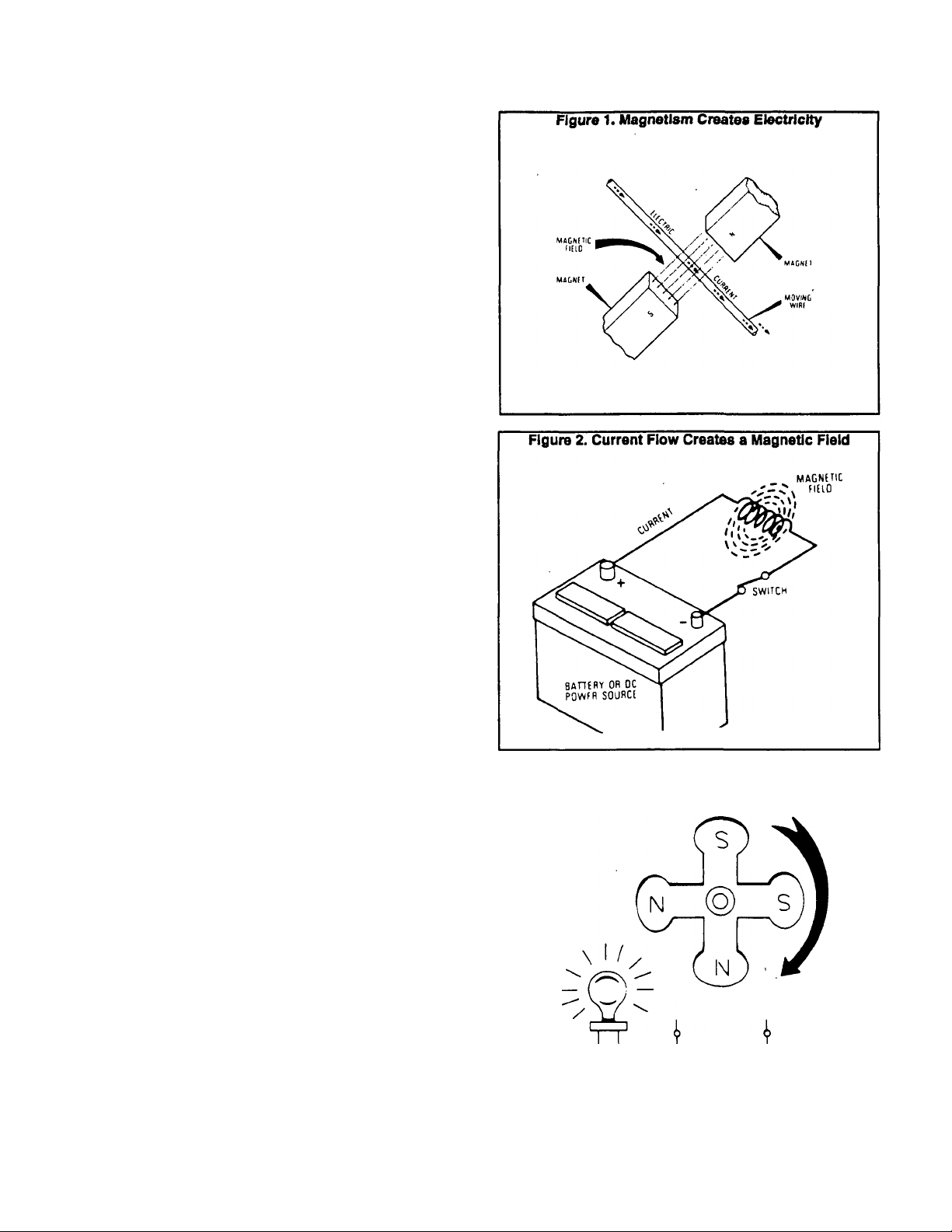
See Figure 1, below. When a conductor is moved
through a magnetic field, an electromotive force (EMF or
voltage) is induced Into the conductor. Movement of the
magnetic field so that It cuts across the conductor will also
create a voltage In the conductor. If the ends of the conductor
are connected to form a complete circuit, current will flow
through the conductor. The direction in which the current
flows depends on the polarity of the magnetic field and the
direction in which the magnetic field (or conductor) is moved.
The amount of voltage Induced into the conductor depends
on the strength or concentration of the magnetic field, i.e., the
stronger the magnetic field, the higher the induced voltage.
See Rgure 2. When current flows through a conductor,
a magnetic field is created around that conductor. The
strength of the magnetic field depends on (a) the amount of
current flow, (b) the number of turns or loops in the conductor.
The polarity of the magnetic field depends on the direction of
current flow through the wire. The following facts should be
evident:
□ If current flow through a conductor can be regulated, the
strength of the magnetic field around the conductor can
be regulated.
D If the strength of a magnetic field can be regulated, the
amount of voltage induced into a conductor by such a
magnetic field can also be regulated.
Figure 3 represents a simple AC generator, in which the
A Simple AC Generator
rotating magnetic field (Rotor) Is a permanent magnet. As the
magnet rotates, its magnetic field cuts across a stationary coil
of wires called a STATOR. When the magnet’s North mag
netic pole moves past the stator windings, current moves
through the wire in one direction. As the South magnetic pole
of the magnet passes the stator wires, current reverses itself
and moves through the stator in the opposite direction.
in the simple generator shown, the strength of the mag
net is fixed. That \ the magnetic field strength cannot be
changed since a permanent magnet is used. Because the
magnetic field strength is fixed, the voltage induced into the
stator coil is constant
If some method of regulating the magnetic field strength
of the magnetic could be found, the voltage induced into the
stator coil could be regulated as well.
Figure 3. A Simple Revolving Field Generator
Paga 1.1-1
Page 6
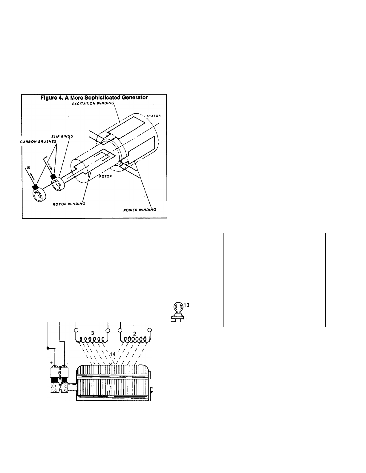
A More Sophisticated Generator
Figure 4 Is a diagram of a more sophisticated generator.
A regulated direct current (DC) is delivered to the rotating
magnet (Rotor), via CARBON BRUSHES and SUP RINGS.
This creates a regulated magnetic field around the Rotor
which cuts across the stationary Stator windings to Induce a
regulated voltage into those windings. When the Stator circuit
is corfipleted by connecting a load, current will flow through
the Stator windings to the load.
Rgure 5, below, Is an operating diagram of a typical AC
A Typical AC Generator
generator. Operation of this typical generator may be briefly
described as follows:
D The ROTOR is attached to the engine’s power takeoff
(PTO) shaft and turns at the same speed as the engine.
D As the ROTOR turns, its magnetic field cuts across the
stationary coils of a STATOR EXCITATION WINDING
and dual STATOR AC POWER WINDINGS. A voltage is
induced into these stationary widings.
□ Unregulated alternating current (AC) is delivered from
the STATOR EXCITATION WINDING to the VOLTAGE
REGULATOR, via an EXCITATION CIRCUIT
BREAKER.
n "Sensing" leads deliver a signal of ACTUAL AC POWER
WINDING voltage to the VOLTAGE REGULATOR.
n The VOLTAGE REGULATOR electronically compares
the ACTUAL AC POWER WINDING voltage to a preset
REFERENCE VOLTAGE and changes №e STATOR
EXCITATION WINDING output to direct current (DC).
□ If ACTUAL POWER WINDING voltage Is less than the
REGULATOR’S preset REFERENCE voltage, REGU
LATOR action will increase direct current flow to the
ROTOR windings. The ROTOR magnetic field strength
will then increase and the voltage induced into the STA
TOR AC POWER WINDINGS will then increase.
□ When ACTUAL POWER WINDING voltage is greater
than the REGULATOR’S preset REFERENCE voltage,
direct current flow to the ROTOR will be decreased by
REGULATOR action to reduce ROTOR magnetic field
strength.
12
-S-
Rgure 5. Operating Diagram of a Typical AC Generator
ITEM
i
2
3
4
5
6
7 SLIP RINGS
11
4^
8
9
10
11
12
13
14
DESCRIPTION
RÓTOF1
STATOR POWER WINDING
STATOR EXCITATION WINDING
FIELD BOOST
ENGINE
BRUSHES
VOLTAGE REGULATOR
SENSING LEADS
THERMAL PROTECTOR
THERMAL PROTECTOR BYPASS
EXCITATION CIRCUIT BREAKER
ELECTRICAL LOAD
MAGNETIC FIELD
Page 1.1-2
Page 7
□ The VOLTAGE REGULATOR will continue to increase
or decrease direct current flow to the ROTOR, In an
attempt to maintain STATOR AC POWER WINDING
voltage at the same value as the REGULATOR’S preset
REFERENCE voltage.
□ When the STATOR AC POWER WINDING circuit is
completed by connecting a load to the winding's AC
output leads, current will flow through the windings and
to the load.
Rotor Residual Magnetism
The Rotor may be considered a permanent magnet since
some residual magnetism is always normally present In the
Rotor windings. As a general rule. Rotor residual magnetism
atone (without regulated excitation current and without field
boost current) will produce a STATOR AC POWER WINDING
output of approximately 2 to 7 volts.
Field Boost
When the engine Is being cranked, direct current is
delivered to the Rotor windings from a source other than the
Stator excitation windings and Voltage Regulator. This direct
current, in effect, Hashes the field" every time the engine is
cranked. By applying field boost current to the Rotor during
cranking, an early "pickup" voltage Is induced into the Stator
windings to turn the Regulator on sooner and provide AC
output more quickly.
Failure of the field boost circuit rrray or may not result In
toss or dropout of AC power winding output voltage, depend
ing on the characteristics of the Individual generator. The
following general rules apply:
D If Rotor residual magnetism atone (without field boost) is
sufficient to turn the Voltage Regulator on and provide
the required pickup voltage, the generator will operate
normally with normal AC output voltage.
G If Rotor residual magnetism atone (without field boost) Is
NOT sufficient to turn the Regulator on and provide the
needed pickup voltage, generator AC output voltage will
not build and will be commensurate with Rotor residual
magnetism (about 2 to 7 volts AC).
G If regulated excitation current to the Rotor is lost. Stator
AC power winding output voltage will drop to a value that
is commensurate with Rotor residual magnetism (2 to 7
volts AC). The magnetic field strength created by field
boost current cannot be considered since it is available
only while cranking.
Figure 6. Field Boost Circuit (Gasoline Fuel System)
STARTER
CONTACTOR
-TO STARTER
§
11 CHOKE
* MODULE
° 1 FROM
*
TO ROTOR •
Figure 7. Field Boost Circuit (LP Gas Fuel System)
BATTERY
-Q)
ENGINE CONTROL
CIRCUIT BOARD
La/v-J
RESISTOR
47 OHM. 2 WATT
TO IGNITION COIL
9 RESISTOR ^9°^
9
-----
W\ T-
9
too OHM 200V.
1 WATT 1 WATT
W-
ENGINE CONTROL
CIRCUIT BOARD
DIODE
AMPY 1 AMf
TO
ROTOR
#
UNITS WITH GASOLINE FUEL SYSTEM;
See Figure 6. Units equipped with a gasoline fuel system
use a choke module (CM) which closes and opens a choke
solenoid (CS) during engine cranking to open and close the
carburetor choke.
UNITS WITH LP GAS FUEL SYSTEM:
Units equipped with a gaseous fuel system do not require
a carburetor choke and do not have a choke module. The field
boost circuit for such units Is shown in Rgure 7. While
cranking, battery voltage is delivered to Terminal No. 8 of an
engine control circuit board, to Wire No. 9, a field boost
assembly. Wire No. 4, and to the Rotor via brushes and slip
rings.
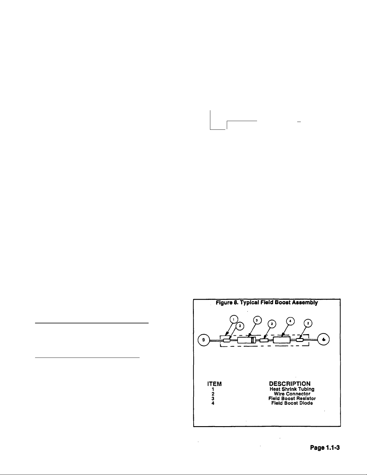
The field boost assembly, shown In Figure 8, consists of
a 100 ohm, 1 watt resistor (1^) and a 200 volt, 1 amp diode
(D2). The diode ensures that current will flow in one direction
only in the circuit. The resistor reduces the battery voltage
(12 volts DC) to approximately 9-10 volts DC.
Page 8
GENERAL:
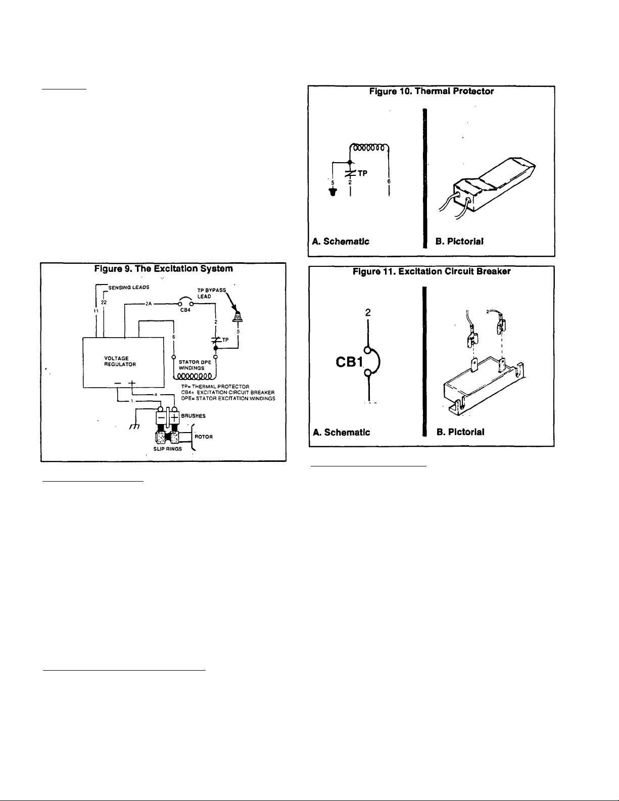
The excitation system is shown schematically in Figure
9. During operation, unregulated AC current from the Stator
excitation winding is delivered to the Voltage Regulator via a
Thermal Protector, Wires 2 and 6, an excitation circuit
breaker (CB4), and Wires 2A and 6. The Voltage Regulator
rectifies and regulates the current flow, which is then deliv
ered to the Rotor windings via Wires 4 and 1, and the brushes
and slip rings. Major components of the excitation system
include the following;
D Stator Excitation (DPE) Winding,
n Thermal Protector (TP).
D Excitation Circuit Breaker (CB4).
D AC Voltage Regulator.
D Brushes and Slip Rings,
n Rotor Assembly.
Excitation System
THERMAL PROTECTOR:
A Thermal Protector (tP) is physically imbedded in the
wire windings of the Stator assembly and electrically con
nected in series with the excitation winding AC output leads
to the Voltage Regulator. The device is a normally-closed (N.
C.), temperature sensitive switch. Should Stator tempera
tures exceed a preset level, the switch contacts will open. The
switch is self-resetting. That is, its contacts will close when
Stator temperatures decrease below a safe, preset level.
If the switch contacts open, excitation winding output to
the Regulator will terminate and the Regulator will shut down.
Generator AC output voltage will then drop to a value com
mensurate with the Rotor’s residual magnetism (about 2 to 7
volts AC).
The thermal protector is NOT accessible and cannot be
replaced. If it has failed open, it can be bypassed by connect
ing excitation lead No. 2 to a bypass lead No. 5. Once the
switch has been bypassed, overtemperature protection is no
longer available.
EXCITATION CIRCUIT BREAKER (CB4):
If this circuit breaker has failed open, the results will be
the same as a Thermal protector that has failed open. That
is, generator AC output will drop to about 2-7 volts AC
(residual).
Page 1.1-4
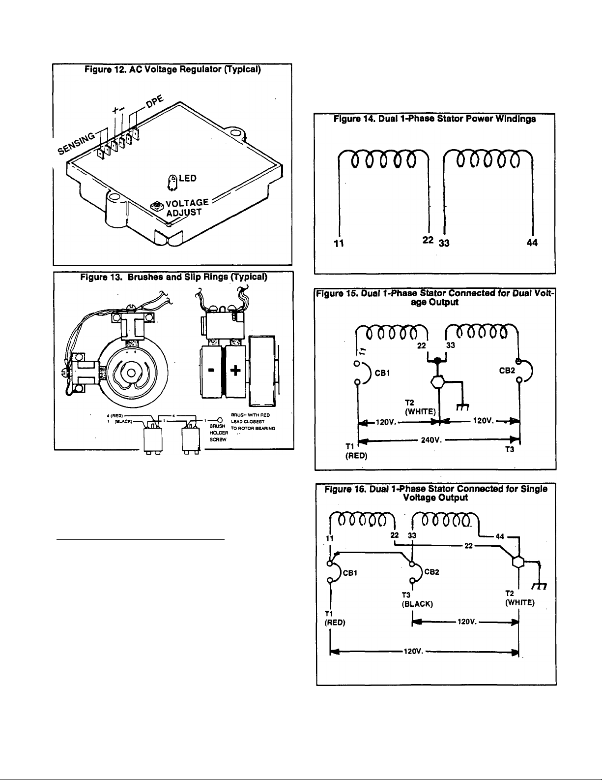
AC VOLTAGE REGULATOR:
See Figure 12. Sensing leads deliver ACTUAL AC power
winding voltage signals to me Regulator via Leads 11 and 22
and Regulator terminals 5 and 6. The Regulator electronically
compares this ACTUAL signal to a preset REFERENCE
voltage, then acts to maintain an ACTUAL voltage that Is
equal to the REFERENCE voltage.
If ACTUAL voltage is less than the preset REFERENCE
voltage, the Reoulator will increase excitation current flow to
the Rotor. The Rotor's magnetic field will then strengthen and
the AC output voltage will increase.
If ACTUAL voltage is greater than preset REFERENCE
voltage. Regulator action will decrease excitation current flow
to the Rotor. The Rotor’s magnetic field strength will drop and
ACTUAL voltage will decrease.
The typical AC Voltage Regulator shown in Figure 12 has
a single amustable potentiometer, used to establish the de
sired REFERENCE voltage.
BRUSHES AND SLIP RINGS:
The Brushes and Slip Rings (Figure 13) allow excitation
current flow to be transmitted rrom a stationary member to a
rotating member. The Slip Rings are actually a part of the
Rotor assembly. As a general rule, the positive slip ring is the
one nearest the Rotor bearing. Wire No. 4 is the positive
brush lead; Wire No. 1 is the negative baish lead.
Page 9
NOTE: At the time thie Manual was written, all NP/IM
Series generators were equipped with the dual, 1-phasa
stator configuration. Some other possible stator config
urations will be mentioned here to cover future possibil
ities.
Stator AC Power Connection Systems
GENERAL:
Any one of several different connection systems are
used on NP and IM Series generators. Theses are(a) dual
1-phase, (b) 3-phase Delta, and (c) 3-phase Wye-Connected
systems.
DUAL WINDING. 1-PHASE SYSTEM:
Figure 14 is a schematic representation of dual 1-phase
Stator AC power windings. Each Stator winding can supply a
120 volts AC output. When the two windings are connected
In series to form a 3-wire connection system, a 240 volts AC
output results.
Connected for Dual Voltage Output Some dual wind
ing systems may have been connected to provide a dual
voltage output (120 and/or 240 volts AC). See Figure 15.
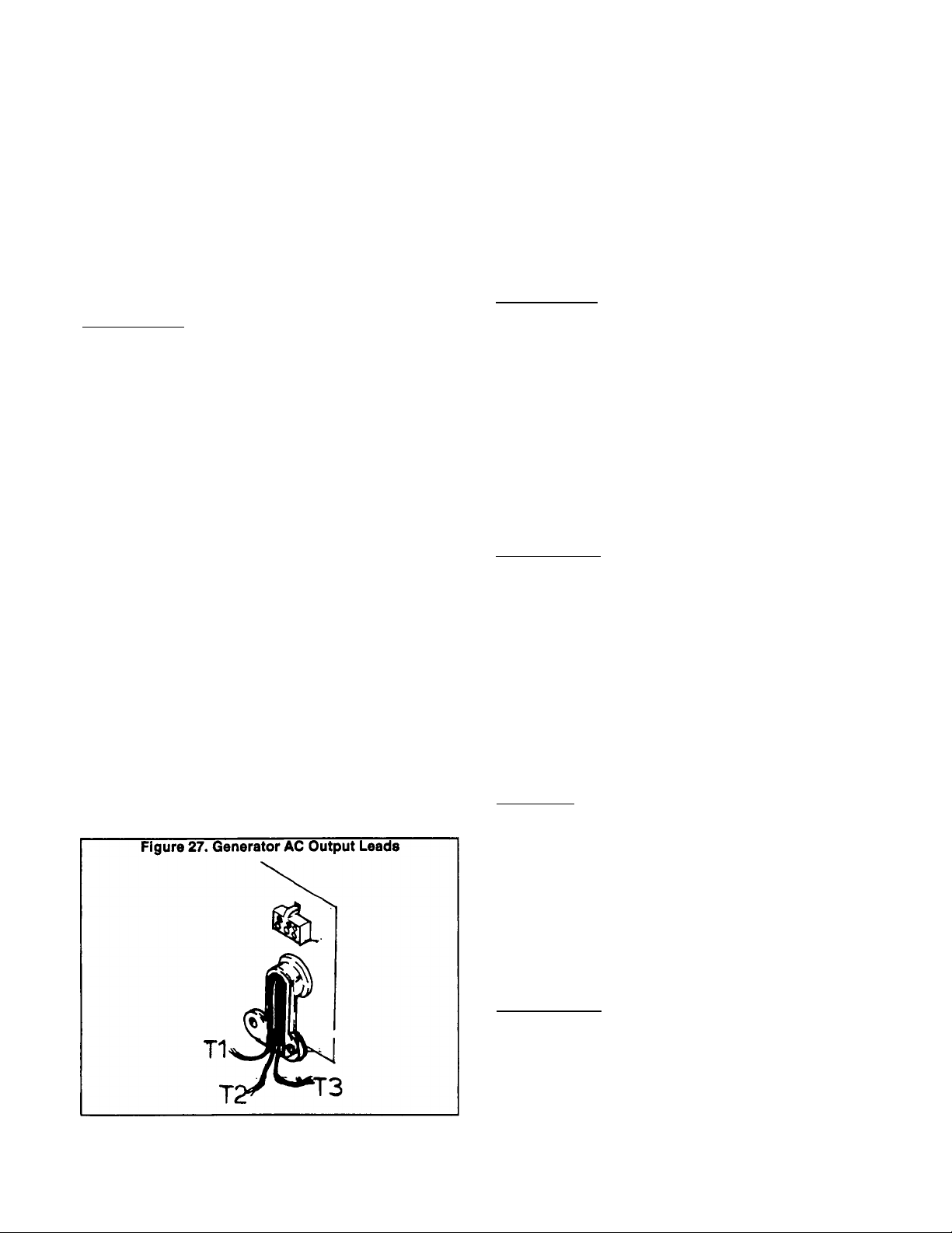
Stator AC output leads 11 (T1) and 44 (T3) form the two hot
leads. The Junction of Stator leads 22 and 33 form the
"Neutral’ line (T2).
Connected for Single Voltage Output: If desired, the
Stator AC ou^ut leads can be reconnected for single voltage
output only (Figure 16). When this Is done, a jumper wire must
be connected between the two main circuit breakers (CB1
and CB2).
Page 1.1-5
Page 10
stator AC Power Connection Systems (Continued)
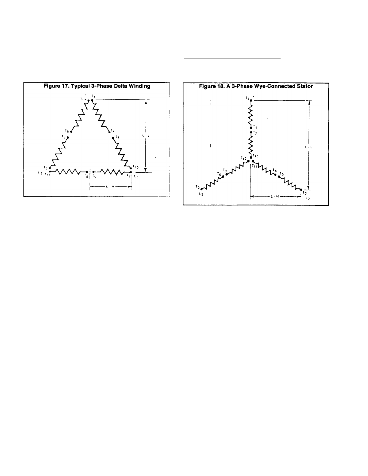
3-PHASE DELTA STATOR SYSTEM:
Figure 17 is a schematic representation of a 3-phase
Delta Stator configuration. Phase rotation is L1-L2-L3. The
“Neutral" line is designated “LO".
3-PH^ASE WYE-CONNECTED SYSTEM:
See Figure 18. This type of Stator consists of six (6) coils
and twelve (12) leads coming out of the Stator. The twelve
leads are reconnectable to supply several different voltages.
Page 1.1-6
Page 11
Section 1.2- MAJOR GENERATOR COMPONENTS
This section will discuss generator disassembly, Inspec
tion of components, and reassembly. See Figure 21 on Page
1.2-2.
Generator Disassembly
To disassemble the generator, proceed as follows. See
Figure 21.
1. Remove the four capscrews, lockwashers and flatwashers
(Items 22, 23 and 24) that retain the REAR BEARING CAR
RIER PLATE (Item 20) to the REAR BEARING CARRIER
(Item 15). Remove the REAR BEARING CARRIER PLATE
(Item 20).
2. Remove the Rear Bearing Carrier GASKET (Item 18).
3. Disconnect wires from BRUSH HOLDERS (Item 16).
4. Remove SCREWS (Item 17) that retain the BRUSH HOLD
ERS (Item 16) to the Rear Bearing CARRIER (Item 15).
Remove the BRUSH HOLDERS (Item 16).
5. Remove hardware that retains the Rear Bearing CARRIER
(Item 15) to the generator mounting base.
6. Remove the four long CAPSCREWS (Item 21), along with
four LOCKWASHERS (Item 10).
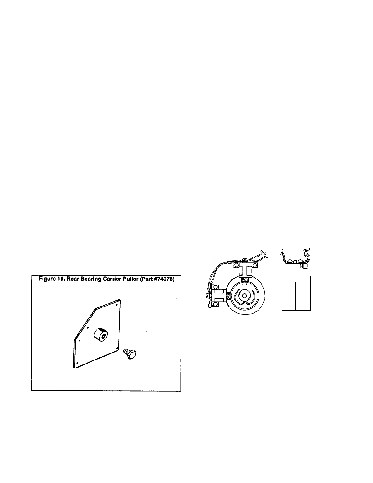
7. A REAR BEARING CARRIER PULLER tool Is available.
See Figure 19. To order the tool, specify Part No. 74078.
a. Retain the PULLER TOOL to the Rear Bearing CAR
RIER (Item 15) using the same M6-1.00 x 8mm screws
ltem 22) that were used to retain the Rear Bearing Carrier
»LATE (Item 20).
i
b. Turn the center bolt on the PULLER TOOL (Figure 19)
clockwise until the Rear Bearing CARRIER (Item 15) is
free of the Rotor bearing.
c. Completely remove the Rear Bearing CARRIER (Item
' 15).
8. Free the STATOR ASSEMBLY (Item 14) from the
BLOWER HOUSING (Item 2). Completely remove the STA
TOR ASSEMBLY (Item 14).
Introduction
12. Remove the ROTOR ASSEMBLY (Kern 1) with the FAN
& RING GEAR (Item 25) attached.
13. Remove CAPSCREWS and LOCKWASHERS (Items 34
and 36) that retain the FLEX PLATE (Item 28) to the engine
flywheel. Remove the FLEX PLATE (Item 28).
14. If the FAN & RING GEAR is to be removed from the
ROTOR (Item 1), proceed as follows:
a. Remove CAPSCREW and LOCKWASHER (Items 30
and 31) that retain the FAN & RING GEAR to the ROTOR.
b. Remove the SPACER (Item 27).
c. Remove the FAN & RING GEAR (Item 25) from the
ROTOR.
NOTE: The FAN & RING GEAR ASSEMBLY (Item 25) Is
retained to the ROTOR shaft by a KEY (Item 26).
Inspection of Major Components
REAR BEARING CARRIER Pj^TE:
Air slots in the Rear Bearing Carrier Plate allow cooling
air to be drawn into the generator by fan action during
operation. These air slots must be kept open and unob
structed. Clean the plate and check for cracks, obvious
damage. Replace the Plate, If necessary.
BRUSHES:
Inspect both Brush Holders and their Brushes. Look for
cracks, chipping, excessive wear. Replace any damaged
Brush Holder. Brushes should be replaced as a complete set.
Inspect Boish Leads No. 1 and 4, replace any damaged or
defective Brush Lead.
Figure 20. Brush Holders, Brushes and Leads
I
9. Remove the hardware that retains the STARTER (Item 40)
to the ENGINE PLATE (Item 29). Remove the STARTER.
10. Remove all fasteners that retain the BLOWER HOUSING
(Item 2). Remove the BLOWER HOUSING.
11. Remove CAPSCREWS (Item 33) that retain the FLEX
PLATE (Item 28) to the FAN & RING GEAR (Item 25).
-
+'
BRUSH WITH RED
LEAD CLOSEST
BRUSH
TO ROTOR BEARING
HOLDER
SCREW
n-rf
REAR BEARING CARRIER:
The Rear Bearing Carrier is an aluminum casting. Clean
the casting and blow dry with compressed air. Inspect care
fully for cracks, damage. An insert is pressed into the bearing
carrier center bore, to accept the Rotor bearing. Use an Inside
micrometer to check the diameter of the Insert. Replace the
Rear Bearing Carrier If its insert’s inside diameter (I.D.) is not
within the following limits:
2.384-2.386 Inches (71.996-72.012mm)
Page 1.2-1
Page 12
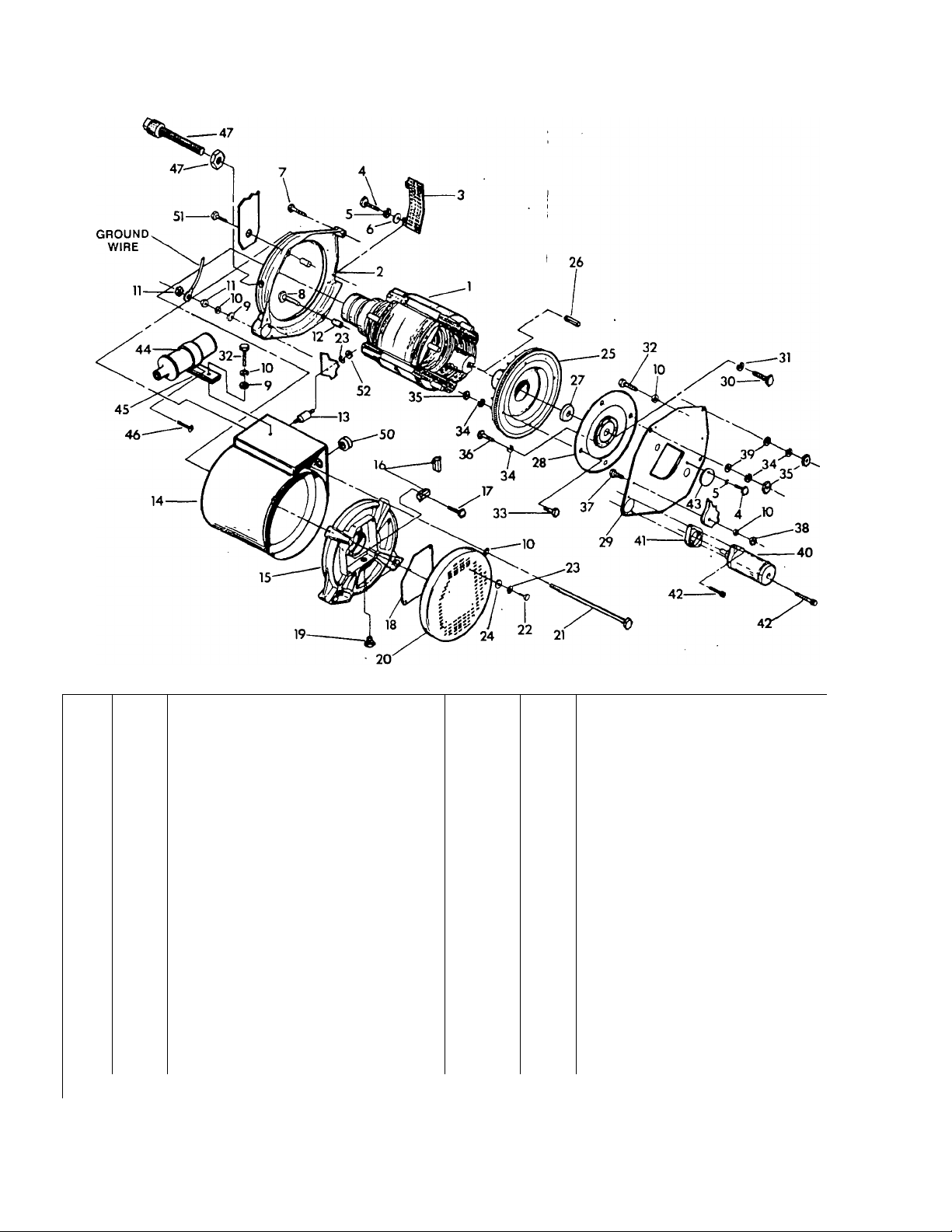
Figure 21. Exploded View of AC Generator Assembly
ITEM
1 1
2 1
3
4 5
5 5
6
7
8
9
10 9
11 3
12 2
13*
14 1
15
16 2
17
18
19
20
21
22
23
24 4
25
26
* User
QTY
i to mount the generator control panel. ** Part of Engine Governor system.. See Part 7.
DESCRIPTION ITEM QTY DESCRIPTION
Rotor Assembly 27
Blower Housing
1
4
1
1
2
4
1
4
1
1
1
4
4
8
1
1
Air Outlet Screen 29 1
Pan Head Machine Screw 30 1
Lockwasher
Flatwasher 32
Hex Head Capscrew 33 4
Hex Head Capscrew
Flatwasher
Lockwasher 36
Hex Nut
Dowel Sleeve
Vibration Dampener 39 3
Stator Assembly
Rear Bearing Carrier 41 1
Brush Holder
Hex Head Screw 43 1
Rear Bearing Carrier Gasket
Flame Arrestor
Rear Bearing Carrier Plate
Hex Head Capscrew
Hex Head Capscrew
Lockwasher 51
Flatwasher
Rywheel & Ring Gear Assembly
3/8* square x 1" Key
28 1
31
34
35 7
37 1
38 1
40
42
44
45
46
47- 1
50 1
52
12
1
1
4
5
1
2
1
1
1
1
4
Magnetic Pickup Assembly
Spacer
Flex Plate
Engine Plate
Hex Head Capscrew
Lockwasher
Hex Head Capscrew
Hex Head Capscrew
Lockwasher
Hex Nut
Hex Head Capscrew
Hex Head Capscrew
Hex Nut
Flatwasher
Starter Motor
Starter Adapter
Hex Head Capscrew
Fan Access Cover
Ignition Coll
Ignition Coll Bracket
Screw
Rubber Grommet
Hex Head Capscrew
Hex Nut
Page 1.2-2
Page 13

STATOR ASSEMBLY;
Clean the Stator can exterior surfaces with a soft brush
or cloth. Use clean, dry, low pressure air (25 psi maximum)
to clean the Stator.
Use an ohmmeter or a volt-ohm-milliammeter (VOM) to
test the resistance of Stator AC power windings and excita
tion (DPE) windings. See Section 1.6.
Use an insulation resistance tester (megohmmeter or
hi-pot tester) to check the condition of stator insulation (see
Section 1.3). If stator insulation is breaking down, dry the
stator by blowing warm, dry air across it for several hours. Do
NOT exceed 185* F. (85‘ C.). If insulation resistance Is still
low after drying, replace the stator assembly.
BLOWER HOUSING:
Clean the cast aluminum blower housing. Inspect the
housing carefully for cracks, damage.
FLEX PLATE;
The flex plate is of 16 gauge steel. Clean the flex plate,
then inspect it carefully for cracks, damage, wear. Check all
holes for elongation and wear.
ROTOR ASSEMBLY;
Use clean, dry, low pressure air (25 psI maximum) to
clean the rotor. Use a volt-ohm-mllliammeter ^OM) to check
the resistance of Rotor windings (Section 1.6).
Check the Rotor bearing for binding, seizing, roughness.
The bearing is pre-lubricated and sealed; It requires no addi
tional lubrication for the life of the bearing. If the bearing Is
defective, replace the Rotor assembly.
Check the keyway in the Rotor’s tapered shaft for wear
or damage. Also, inspect the drive key.
Inspect the slip rings. A dull or tarnished appearance
indicates oxidation on the slip ring surface. If necessary,
clean the slip rings with fine sandpaper. DO NOT USE ANY
METALLIC GRIT TO CLEAN SLIP RINGS.
Use an Insulation resistance tester (megohmmeter or
hi-pot tester) to check fhe Rotor for Insulation breakdown. If
insulation resistance Is low, dry the Rotor with heated, dry air.
DO NOT EXCEED 165* F. (85 C.). If the insulation resistance
is still low after drying, replace the Rotor assembly.
FAN AND RING GEAR ASSEMBLY:
During factory assembly, the ring gear is heated to 400*
F. and the blower fan is installed. The entire assembly is then
statically balanced. If the fan and ring gear must be replaced,
replace It as an assembly.
Page 1.2-3
Page 14
Section 1.3- INSULATION RESISTANCE TESTS
Effects of Moisture and Dirt
The insulation in RV and IM generators is moisture
resistant. However, prolonged exposure to moisture will grad
ually decrease the resistance of Stator and Rotor insulation.
If moisture is allowed to remain in contact with generator
windings, some of the moisture will be retained in cracks and
voids of the iunsulation. This will result in a reduced insulation
resistance and, eventually, the unit’s AC output will be af
fected.
Dirt can make the problem worse since it tends to hold
the moisture Into contact with the windings.
Salt, as from sea air, can also worsen the problem since
salt absorbs moisture from the air. When salt and moisture
combine, they make a good electrical conductor.
Because of the detrimental effects of dirt and moisture,
the generator should be kept as clean and dry as possible.
Stator and Rotor windings should be tested periodically with
an insulation resistance tester such as a megohmmeter or
hi-pot tester. If the insulation resistance is excessively low,
drying may be required to remove moisture. After drying, a
second test of the Insulation should be performed. If resis
tance Is still low after drying, replacement of the defective
windings may be necessary.
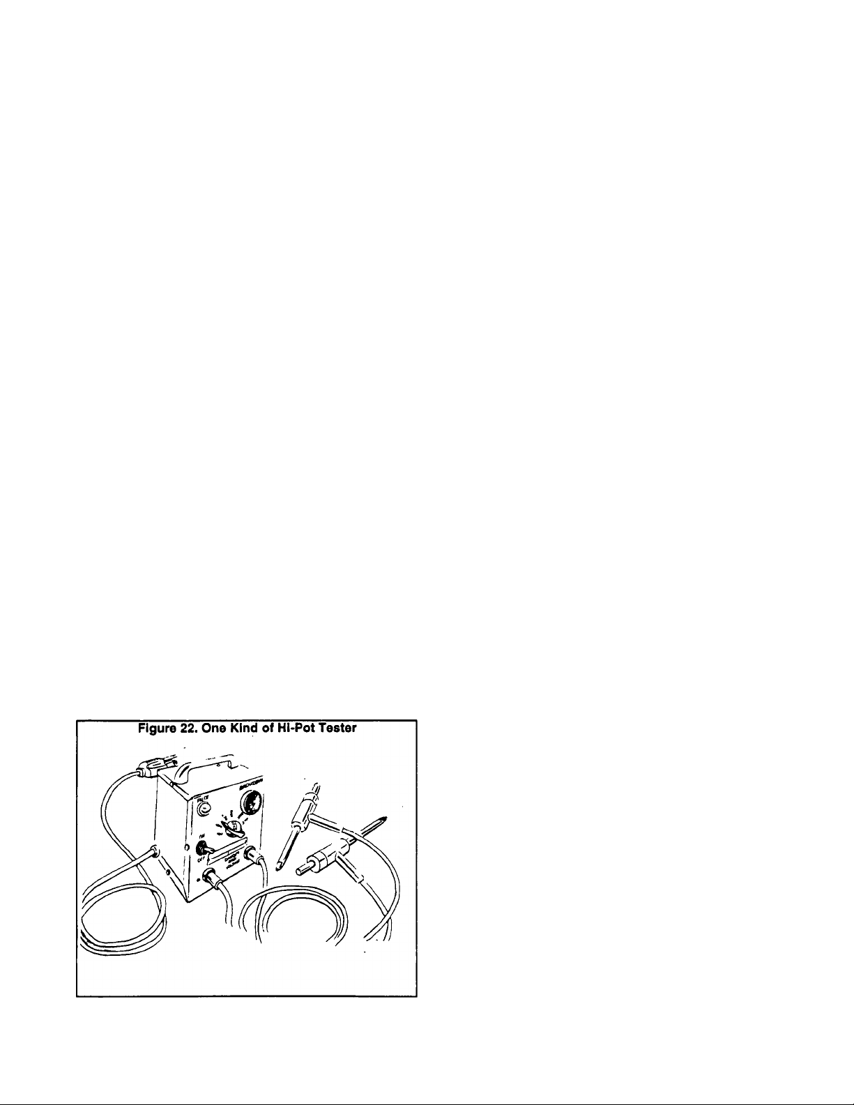
Insulation Resistance Testers
Figure 22 shows Just one type of hi-pot tester. The tester
shown is one of many brands that are commercially available.
It has a "Breakdown^ lamp which will glow to Indicate insula
tion breakdown during the test.
Normally, the resistance of insulation is measured on the
order of millions of ohms, it can be measured w'rth a device
called a 'megger', which is a megohm meter (meg is for
million) and a power supply. The power supply voltage varies
but the most common Is 500 volts. A megger voltage over 500
is NOT recommended.
When using a hi-pot tester or megger to measure Insu
lation resistance, be sure to follow the manufacturer's instruc
tions carefully.
CAUTION: Before attempting to measure Insula
tion resistance In any winding, first disconnect
any electronic components, regulators, diodes,
surge protectors, protective relays, etc., from the
circuit. Such components will be destroyed by the
high voltages generated by a megger or hl-pot
tester.
To measure Insulation resistance, connect one tester
lead to the leads for the winding to be tested and the other
tester lead to the generator frame. Make sure no leads of the
part being tested are touching any metal parts of the gener
ator. If the 'Neutral' is grounded, it must be disconnected.
Follow the tester manufacturer’s instructions and perform the
resistance test.
Insulation Resistance- Main Stator
All stator leads (No. 11, 22, 33, 44, 2 and 6) must be
Isolated from ground and connected together. Connect one
hi-pot or megger test lead to the main stator leads. Connect
the other hi-pot or megger lead to the generator grounding
stud. Set the hi-pot tester or megger voltage to '500'. Follow
the tester manufacturer’s Instructions and take the reading.
Do not apply the voltage for longer than one (1) second.
If a hi-pot tester like the one shown in Figure 22 is being
used, a 'Breakdown' lamp on the tester will glow during the
one second test to indicate an Insulation breakdown.
If a megger is used to perform the test, the minimum
acceptable value can be calculated using the following for
mula:
Minimum Insulation в
Resistance (Megohms)
Example: For a generator rated 240 volts AC:
2^+1b 1.24 Megohms
Generator Voltage +1
-------------TOOO
------
1000
H the reading Is below the recommended value, the
winding must be dried out
Rotor insuiation Resistance
Before testing Rotor insulation, гтшке sure the Rotor Is
completely Isolated. This can be done by removing both
brush holders with their brushes.
Connect one hi-pot tester or megger lead to the positive
Rotor slip ring, the other test lead to a clean frame ground
(such as the Rotor shaft). Set the tester to '500' volts and
apply voltage - DO NOT APPLY VOLTAGE LONGER THAN
ONE SECOND.
If a hi-pot tester is used. Its 'Breakdown' lamp will come
on to Indicate an insulation breakdown.
If a megger Is used, the minimum acceptable value Is 1.5
megohms. ,
If insulation Is breaking down under the applied voltage,
the Rotor must be dried out. After drying, retest the Rotor. If
insulation still breaks down after drying, replace the Rotor
assembly.
Greasy dirt or dirt that Is caked may be loosened with a
soft brush or a clean, damp cloth. A vacuum system may be
used to clean up loosened dirt. Loose dust and dirt may also
be blown away with clean, dry, low pressure air (25 psi
maximum).
Drying the Generator
To dry the generator without disassembling it, proceed
as follows:
1. Open the generator’s main circuit breaker. NO ELECTRI
CAL LOADS MUST BE APPLIED TO THE UNIT WHILE
DRYING.
Page 1.3-1
Cleaning the Generator
Page 15

Drying the Generator (Continued)
2. Disconnect Wires No. 4 from the Voltage Regulator.
3. Provide an external source to blow warm, dry air through
the generator. DO NOT EXCEED 185* F. (85* C.).
4. Start the generator and iet it run for 2 or 3 hours.
5. Stop the engine and retest Stator and Rotor insulation for
breakdown.
Page 1.3-2
Page 16
Section 1.4- INTRODUCTION TO TROUBLESHOOTING
A revolving field RV/IM type generator does not have a
Introduction
large number of parts. However, the parts are expensive. For
that reason, a 'parts replacement' method of troubleshooting
Is not cost effective. A basic understanding of generators is
required if one Is to achieve effective troubleshooting and
repair. The technician must understand why generators be
have or don’t behave as they should. This section is Intended
to introduce the service technician to some of the fundamen
tals of troubleshooting generator problems.
DANGER: RV AND IM TYPE GENERATORS PRO
DUCE EXTREMELY HIGH AND DANGEROUS
VOLTAGES. CONTACT WITH LIVE WIRES AND
TERMINALS MAY RESULT IN HAZARDOUS AND
POSSIBLY FATAL ELECTRICAL SHOCK. ONLY
PERSONNEL WHO HAVE BEEN TRAINED IN THE
SERVICING AND REPAIR OF RV/IM GENERA
TORS SHOULD ATTEMPT TO TROUBLESHOOT,
TEST OR REPAIR SUCH EQUIPMENT.
Tools and Equipment
The generator service technician should have a well
stocked tool box having a good selection of common hand
tools. Such a tool box should be equipped with wrenches in
both english and metric sizes. A selection of nut drivers
(english and metric) is also recommended. In addition to
common hand tools, the following specialized equipment
should be available;
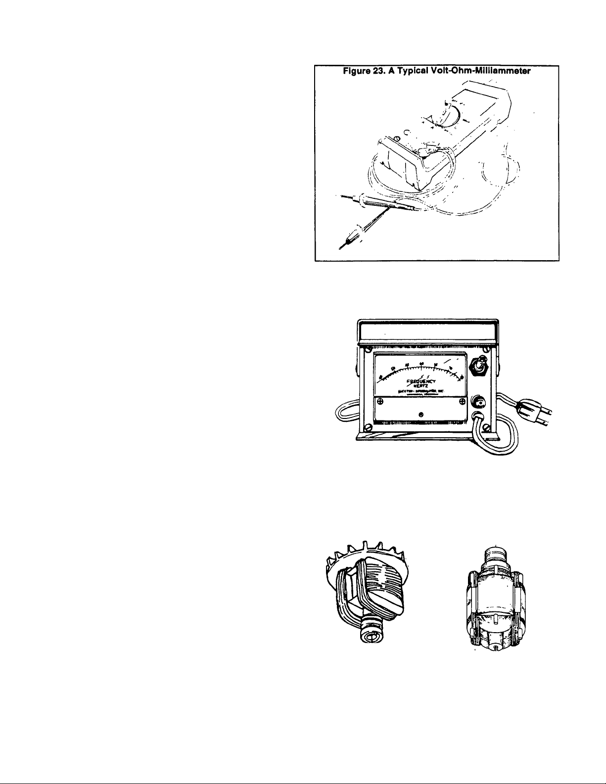
Figure 24. A Typical Frequency Meter
1. Volt-Ohm-Milliammeter or VOM
a. An accurate VOM Is necessary fortesting, adjusting and
troubleshooting.
b. Simply having a VOM is not enough- the technician must
be familiar with electrical circuits, must be able to read
wiring diagrams and electrical schematics, and must be
able to use the VOM effectively.
C. An accurate digital type VOM is recommended.
2. Frequency Meter
a. Frequency meter reads alternating current (AC) fre
quency, in HERTZ or CYCLES PER SECOND.
b. Generator AC output frequency must be known in order
to check and adjust engine-generator operating speed.
See "ROTOR ROTATIONAL SPEECt in this section.
3. Insulation Resistance Tester
a. See Section 1.3, ‘INSULATION RESISTANCE TESTS".
b. This tester will allow the user to test Rotor and Stator
Insulation for breakdown under an applied voltage.
4. Load Bank- will permit a known electrical load to be applied
to the generator, i.e., fortesting and adjustment of the gener
ator under load.
Rotor Rotational Speed
The revolving field (Rotor) is directly connected to the
engine crankshaft and will rotate at the same speed as the
engine. Engine speed is held nearly constant by an engine
governor. Some generator models utilize a constant speed,
MECHANICAL governor; other models may be equipped with
an ELECTRONIC governor. See Part 7, "ENGINE SPEED
CONTROL SYST^Kr.
Generators may be equipped with either a 2-pole or a
4-pole Rotor. A 2-poie Rotor has a single North magnetic pole
and a single South magnetic pole. A 4-pole Rotor has two
North magnetic poles and two South magnetic poles. The
following apply to 2 and 4-pole Rotor assemblies:
A. 2-Pole
Figure 25. Typical 2 and 4-Pole Rotors
B. 4-Pole
Page 1.4-1
Page 17
Rotor Rotational Speed (Continued)
1. A 4-Pole Rotor must be operated at 1800 rpm to supply a
60 Hertz AC output frequency: or at 1500 rpm for a 50 Hertz
AC output frequency.
2. A 2-pole Rotor must be operated at 3600 rpm for a 60 Hertz
AC output frequency: or at 3000 rpm for a 50 Hertz frequency.
The following formulas apply to (a) frequency, (b) rpm, and
(c) number of Rotor poles:
FREQUENCY = RPM X NO. OF ROTOR POLES
2x60
RPM o
NO. OF ROTO№ 2 X 60 X FREQUENCY
POLES RPM
2 X 60 X FREQUENCY
NO. OF ROTOR POLES
Relationship of Voltage & Frequency
The generator’s AC voltage regulator mounts a single
adjustable potentiometer, used for adjustment of tne
Regulator’s REFERENCE voltage (see ’EXCITATION S/S-
TEAf on Page 1.1-4). The potentiometer is called simly a
'Voltage Adjust Potentiometer* and is adjusted with the gen
erator running at no-load and at a specific operating speed.
It is important that the engine speed governor be properly
adjusted before the Voltage Adjust Potentiometer setting is
attempted. The no-load AC frequency and voltage settings
should be as follows:
1. Shut the generator engine down.
2. Connect a voltmeter to the generator’s AC output
leads.
3. Disconnect Wires No. 4 and 1 from the Voltage Reg
ulator.
4. Connect a jumper wire from terminal #1 (Wire #15) of
the engine control circuit board to the terminal end of Wire #4
(just disconnected from the Reguiator).
5. Connect a jumper wire from terminal #2 of the engine
control circuit board (Wire #0, ground) and to the terminal end
of Wire #1 Gust disconnected from the Regulator).
6. Start the generator and let It run at no-load (main
breakers open) and at its rated speed.
7. Read the generator’s AC output voltage from the
voltmeter connected In Step 2. Reading should be approxi
mately one-half rated voltage (about 40-60 volts line-to-neutral or 80-120 volts line-to-line).
8. Shut the generator down.
9. Reconnect Wires No. 1 and 4 to the Voltage Regulator.
If voltage reading is normal in Step 7, the Wires #1 and
4 circuit, brushes and slip rings. Rotor and Stator are working
satisfactorily. The problem is In the circuit that Includes (a)
stator excitation windings, (b) thermal protector, (c)excitation
circuit breaker (CB4), (d) Wires 2 and 6, and (e) Voltage
Regulator.
NOTE: Field boost current la available to the Rotor only
while the engine Is cranking. Loss of excitation current
flow to the Rotor will result In a decrease In generator AC
output voltage to a value commensurate with Rotor re
sidual magnetism (about 2 to 7 volts AC),
1. For Units Rated 120/240 Volts at 60 Hertz: Set AC
frequency to 60.5-63.5 Hertz and Voltage to 121-127 volts
AC (line-to-neutral), or 242-254 volts AC (line-to-line).
2. For units rated 110/220 volts at 50 Hertz: Set AC fre
quency to 49-52 Hertz and voltage to 108-112 volts (line-toneutral).
Visuai inspection
Quite often problems that occur in the generator can be
detected by making a thorough visual inspection. Remove
covers and look for any obvious problems. Burned windings,
broken connections, leads, mounting brackets, etc., can usu
ally be Identified. Also look for loose or frayed insulation,
loose or dirty electrical connections, broken wires.
Verify that the generator AC output leads are properly
connected for (a) single voltage outpiut, or (b) dual voltage
output. See 'STATOR AC POWER CONNECTION SV%-
TEMSr on Page 1.1-5.
Check for any foreign objects, loose nuts, bolts, and
electrical connectors. Clear away paper, leaves, snow, build
ing materials, etc., that might be sucked into the generator.
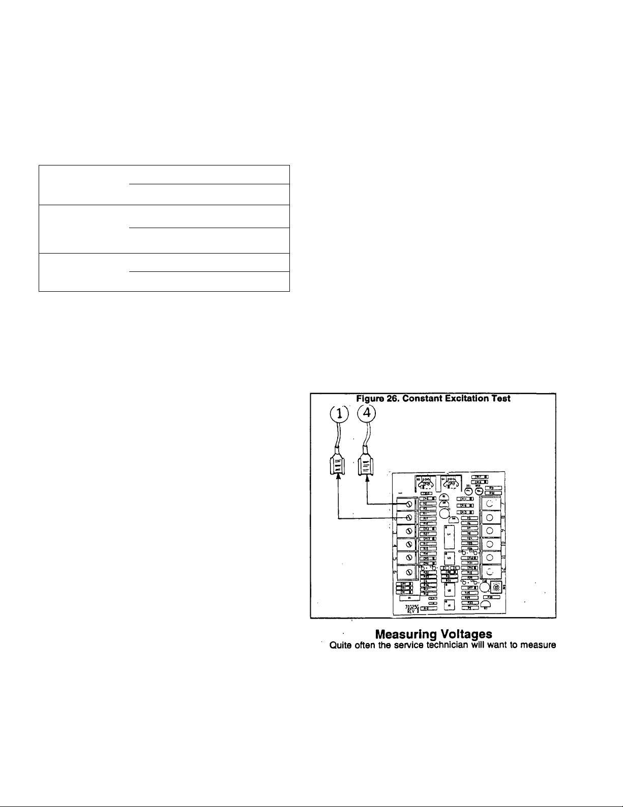
Constant Excitation Test
The generator’s AC output voltage will vary with Rotor
speed, generator design, connected loads, and excitation
current to the Rotor, if the generator speed and excitation
cunenttothe Rotor are known, the no-load AC output voltage
can be measured and compared to the design value. A
problem can be isolated to (a) Stator Excitation (OPE) wind
ings to Voltage Regulator circuit, including the Regulator, or
(b) Voltage Regulator to Rotor circuit, excluding the Regula
tor, or (c) the Stator assembly. Perform the test as follows:
a DC or AC voltage.
The DC voltage most often measured will be battery
voltage (12 volts DC).
When measuring AC voltages, the generator will have to
be running at rated speed and may have some of the protec
tive guárete and covers removed. BE CAREFUL. It is best to
shut the unit down when connecting meters. Use the meter’s
instruction manual to verify its operation and limitations.
Page 1.4-2
Page 18

Alternating current measurements can be taken with a
Measuring Current
'clamp-on* type ammeter. Amperage should never exceed
the nameplate rating when running the intended electrical
load(s).
Resistance of the main stator windings is very low. Some
meters are not able to read such a low resistance and, for that
reason, use of a very sensitive digital type meter is recom
mended. A standanj VOM can be used to check for continuity,
shorts or grounded condition.
Effects of Engine Power
The generator engine must provide adequate power to
operate the generator at rated load. The greater the load
current (amperage) or load watts, the greater the engine
power that is needed. As a general rule, approximately 2
engine horsepower is needed for each 1000 watts (1.0 kW)
of generator power.
If the generator’s wattage/amperage capacity is ex
ceeded, engine power may not be sufficient to handle the
Increased load. The result will be a decrease in engine speed
(rpm) and a corresponding reduction int AC output frequency
and voltage.
A badly worn engine, one that has lost compression, or
one with a mechanical problem may not be able to handle a
load within the generator’s rated capacity. Problems with
generator AC output are often the direct result of an engine
problem, rather than a generator problem.
If engine speed, AC frequency and voltage are normal
when the generator Is running aty no load, but deteriorate
when electrical loads are applied, an underpowered engine
may be the cause of the problem.
Measuring Resistance
Page 1.4-3
Page 19
Section 1.5- TROUBLESHOOTING FLOW CHART
TEST 1-CHECK NO-LOAD
VOLTAGE AND FREQUENCY
VOLTAGE &
FREQUENCY
BOTH GOOD
VOLTAGE &
FREQUENCY
BOTH HIGH
IVQEVOLTAGE LOW,
FREQUENCY
GOOD
VOLTAGE
AND
FREQUENCY
Page 1.5-1
Page 20

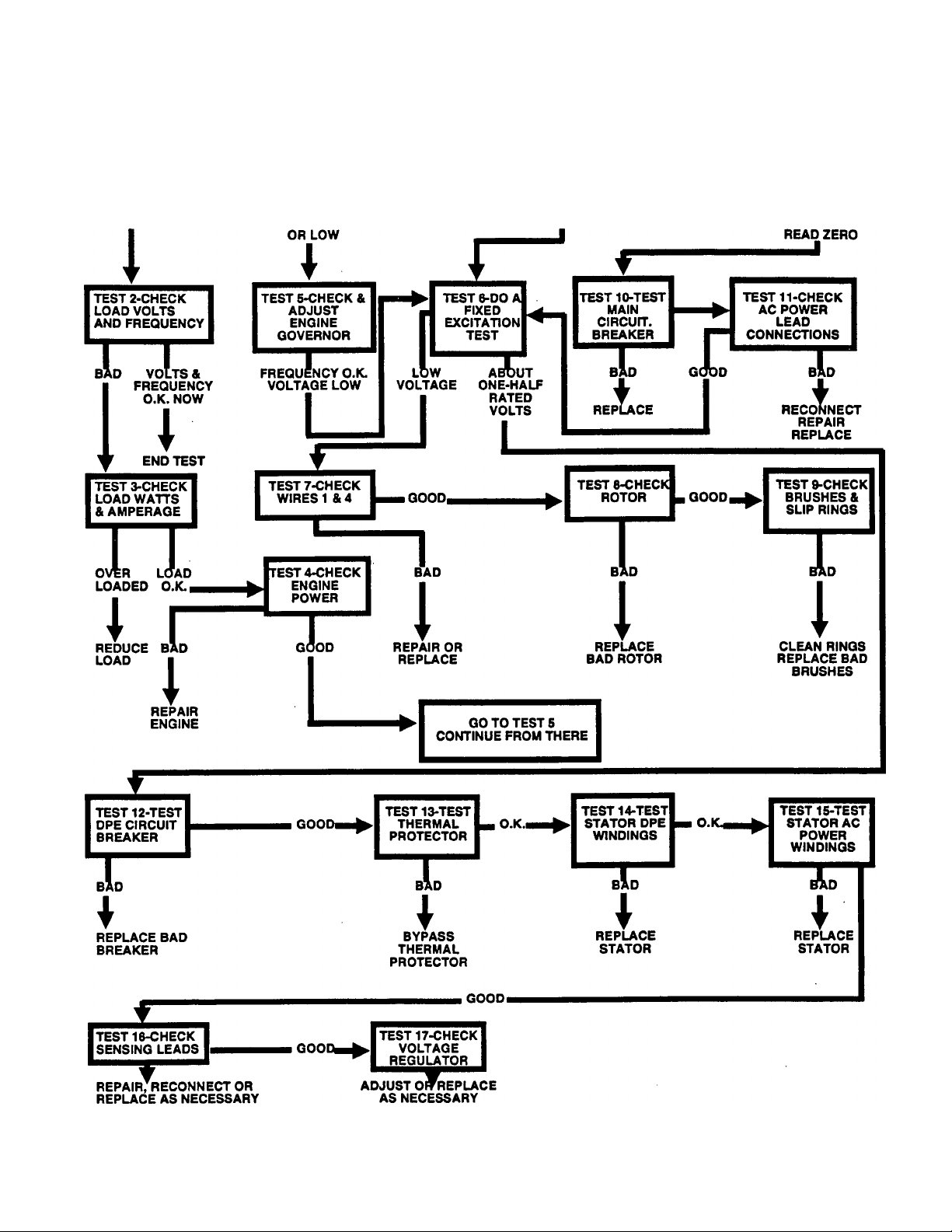
Using the Troubleshooting Flow Chart
When a problem occurs with an RV/IM series generator
set, the first step is to determine exactiy what that problem is.
The nature of the problem can usually be found by checking
the unit’s no-load AC output voltage and frequency. This is
Test 1 in the Flow Chart. A check of the no-load voltage and
frequency will usually end with one of the following results;
1. Voltage and frequency are both good. If this is the case,
the next step is to check voltage and frequency with electrical
load applied.
2. Voltage and frequency are both high or bw, usually an
engine governor problem, I.e., governed speed too high or
too low.
3. Voltage is low, but AC frequency is good. The cause of
this problem can often be found by perfomiing a "Fixed
Excitation" test
4. Voltage and frequency read "zero".
Once the nature of the problem is defined, the cause of
the problem can usually be found by following the explana
tions and arrows in the Flow Chart
Use the'TROUBLESHOOTING FLOWCHART in con
junction with test instructions in Section 1.6, 'TROUBLE
SHOOTING TEST PROCEDURES'.
r-\
Page 1.5-2
Page 21
Section 1.6- TROUBLESHOOTING TEST PROCEDURES
The following numbered tests may be performed in con
Introduction
junction with identically numbered tests in the "TROUBLE
SHOOTING FLOW CHART (Section 1.5). The "FLOW
CHART* has been carefully planned to prevent guesswork
and to locate most common generator problems.
NOTE: Quite often the cause of a problem can be deter
mined by completing a close visual Inspection of the
generator. See "VISUAL INSPECTION" on Page 1.4-2.
Test 1> Check No-Load Voltage and Fre
quency
DISCUSSION:
When a generator problem occurs, the first step Is to
identify the problem. This can usually be accomplished
quickly by checking the no-load AC ouÿut voltage and fre
quency. Once the exact problem has been identified, the
cause of the problem can usually be isolated by continuing
orderly tests as shown in the "TROUBLESHOOTING FLOW
CHART".
NOTE: You will have to determine whether the AC leads
have been connected for single voltage output only (120
volts, 60 Hertz orilo volts, SO Hertz); or for dual voltage
output (120/240 volts, 60 Hertz or 110/220 volts, 50 Hertz).
See "STATOR AC POWER CONNECTION SYSTEMS" on
Page 1.1-5.
PROCEDURE:
1. Connect an AC voltmeter and AC frequency meter across
the generator’s AC output leads. Open main circuit breaker.
a. If connected for single voltage AC output, connect the
meters across leads T1 and 12.
b. If connected for dual voltage output, connect meters
across leads T1 and 12 or 12 and T3 for a 120 volts, 60
Hertz (or 110 volts, 50 hertz) reading. For a 240 volts, 60
Hertz (or 220 volts, 50 hertz) reading, connect meter test
leads across generator leads T1 andT3.
2. Start the generator engine, let It stabilize and wami up.
3. Read the AC output voltage and frequency. Readings
should be as follows:
a. For units rated 120/240 volts, 60 hertz; readings should
be 121 -126 volts at 61 -63 Hertz; or 242-252 volts at 61 -63
Hertz.
b. For units rated 110/220 volts, 50 hertz; readings should
be 111 -113 volts at 51 -53 Hertz; or 222-226 volts at 51 -53
Hertz.
RESULTS:
1. If the no-load voltage and frequency are good, go to Test
2.
2. If no-load voltage and frequency are both high or low, go
to Test 5.
3. If frequency reads good but voltage Is low, go to Test 6.
4. If voltage and frequency read "zero", go to Test 1.0.
Test 2- Check Load Voltage and Fre
quency
DISCUSSION:
Generator problems are sometimes caused by exceed
ing the wattage/amperage capacity of the unit. What appears
to be a generator problem may, in fact, be caused by an
engine that has lost power. The following facts apply:
D Quite often, the maximum wattage that can be supplied
by a generator Is limited by available engine power.
When connected loads exceed a critical point, engine
speed will droop. With a reduction in engine speed will
come a voltage and frequency loss.
O It is possible that an engine can lose power to the extent
that even normal rated generator output power can be
achieved. Engine speed, frequency and voltage can then
droop before a unit's rated maximum capacity has been
reached.
PROCEDURE:
If no-load AC output voltage and frequency were within
limits, but operational problems occur when electrical loads
are applied, check the output voltage and frequency under
load as follows:
1. Connect an AC voltmeter and frequency meter across the
generator’s AC output leads. Close the main circuit breaker.
2. Start the generator, let it stabilize and warm up.
3. Apply an electrical load to the generator equal to its rated
maximum wattage/amperage capacity.
4. Read the voltage and frequency.
a. Units rated 120/240 volts, 60 Hertz: Readings should
be at least 116 volts and 58 Hertz (or higher).
b. Units rated 110/220 Volts, 50 Hertz: Readings should
be at least 107 volts, 48 Hertz (or greater).
RESULTS:
1. If load voltage and frequency are below limits, go to Test
3.
2. If voltage and frequency are good, discontinue tests.
Test 3- Check Load Watts and Amperes
DISCUSSION:
If the unit's AC output frequency and voltage drop below
limits when electrical loading is applied, it is possible that the
rated capacity of the generator has been exceeded.
PROCEDURE:
Add up wattage ratings of all electrical loads applied to
the generator at one time. This total should not be greater
than the unit’s rated maximum wattage capacity. If desired, a
clamp-on ammeter may be used to measure load current. The
unit’s rated maximum amperage capacity should not be ex
ceeded.
Page 1.6-1
Page 22

Test 3- Check Load Watts and Amperes
(Continued)
NOTE; The best way to check load wattage and amperage
la to use a load bank. A load bank will allow the operator
to apply a known wattage/amperage load to the generator
and win permit voltage, frequency and amperage to be
read directly from the load bank.
RESULTS;
1. If the generator Is overloaded, reduce the load to the unit’s
rated capacity.
a. If voltage and frequency are excessively low at the unit’s
rated capacity or less, go on to Test 4.
b. If voltage and frequency are acceptable at the unit’s
rated capacity, discontinue tests.
2. If the load Is within the unit’s rated capacity, but load
voltage and frequency are excessively low, go on to Test 4.
Test 4- Check Engine Power
DISCUSSION:
If excessive rpm and frequency droop occurs when
electrical loads are applied, the engine may be underpowered
due to a malfunction.
PROCEDURE:
Check the engine for (a) adequate air flow, (b) clogged
air cleaner, (c) incorrect timing, (d) mechanical failure, etc.
RESULTS:
1. If engine problems are found, repair the engine as neces
sary.
2. If engine checks good, go on to Test 5.
Test 5- Check & Adjust Engine Governor
DISCUSSION:
If engine speed (and frequency) droop excessively under
load, the engine governor may require adjustment
PROCEDURE:
Refer to Part 7, "ENGINESPEED CONTROL SYSTEM-.
Governor adjustment procedures for both the mechanical and
electronic type governors can be found in Part 7.
RESULTS:
1. It, after governor adjustment, voltage and frequency output
at no-load and under load are good, discontinue tests.
2. If, after governor adjustment, frequency Is good, but volt
age is excessively low, go on to Test 6.
Test 6- Do a Fixed Excitation Test
DISCUSSION:
See "CONSTANTEXCITATION TEST on Page 1.4-2.
PROCEDURE:
’TEST" on Page 1.4-2.
RESULTS:
1. If voltage is excessively low, go to Test 7.
2. If about 1/2 rated volts is indicated, go to Test 12.
Test 7- Check Wires 1 and 4
DISCUSSION:
the fixed or constant excitation test (Test 6) consisted
of applying battery direct current to the Rotor windings (12
volts DC). With the normal excitation circuit disconnected,
application of battery current should result In approximately
one-half rated voltage output (about 60-80 volts AC).
If batteiy current is applied and AC output voltage te
excessively low, a problem exists in Wires 1 and 4 from the
Regulator, or the brushes and slip rings, or the Rotor or stator
windings.
If the application of battery current results in an AC output
of about one-half rated volts, but AC output voltage is low
during normal operation, a problem exists in the stator exci
tation (DPE) windings, in the excitation circuit between the
stator DPE windings and the Regulator, or in the Regulator
itself.
PROCEDURE:
1. Visually inspect Wires 1 and 4, between the Voltage
Regulator and the brushes.
2. Use a VOM to test Wire 1 (between the brushes and
Regulator) for continuity.
3. Check Wire 4 (between the brushes and Regulator) for
continuity.
4. Check that Wires No. 1 and 4 are properly connected at
the Regulator and at the brushes.
RESULTS:
1. Repair, replace or reconnect wires 1 and 4 as necessary.
2. If Wires 1 and 4 are good, go to Test 8.
Test 8- Check Rotor
DISCUSSION:
Problems will be encountered if the Rotor Is (a) open, (b)
shorted, or (c) grounded. This test will determine If any of
these problems exist in the Rotor.
PROCEDURE:
1. If Rotor Is installed, remove the bearing carrier cover to
gain access to the Rotor brushes and slip rings.
2. Disconnedct Wires 1 and 4 from the brushes, to prevent
Interaction.
3. Connect the positive test lead of an ohmmeter to the
positive slip ring, the common test lead to the negative slip
ring. The positive slip ring Is the one nearest the Rotor bearing
(see Figure 28). The meter should indicate the resistance of
the Rotor windings, approximately 8.5 ohms (plus or minus
10%) for both 8 and 10 kW models.
4. Set a VOM to a very high resistance scale, such as
■Rxl 0,000" or "RxlK". Zero the meter. Connect the positive
VOM test lead to the positive slip ring. Connect the negative
VOM test lead to a clean frame ground, such as the Rotor
shaft. The meter should read "infinity".
RESULTS:
1. In Step 3, a very high resistance or "infinity" Indicates an
open or partially open condition. Replace the Rotor.
2. In Step 3, a very low resistance indicates a shorted or
groundea condition. Replace the Rotor.
3. In Step 4, any reading other than "infinity" Indicates a
groundea condition. Replace the Rotor.
4. If all Rotor readings are good, go to Test 9.
Page 1.6-2
Page 23
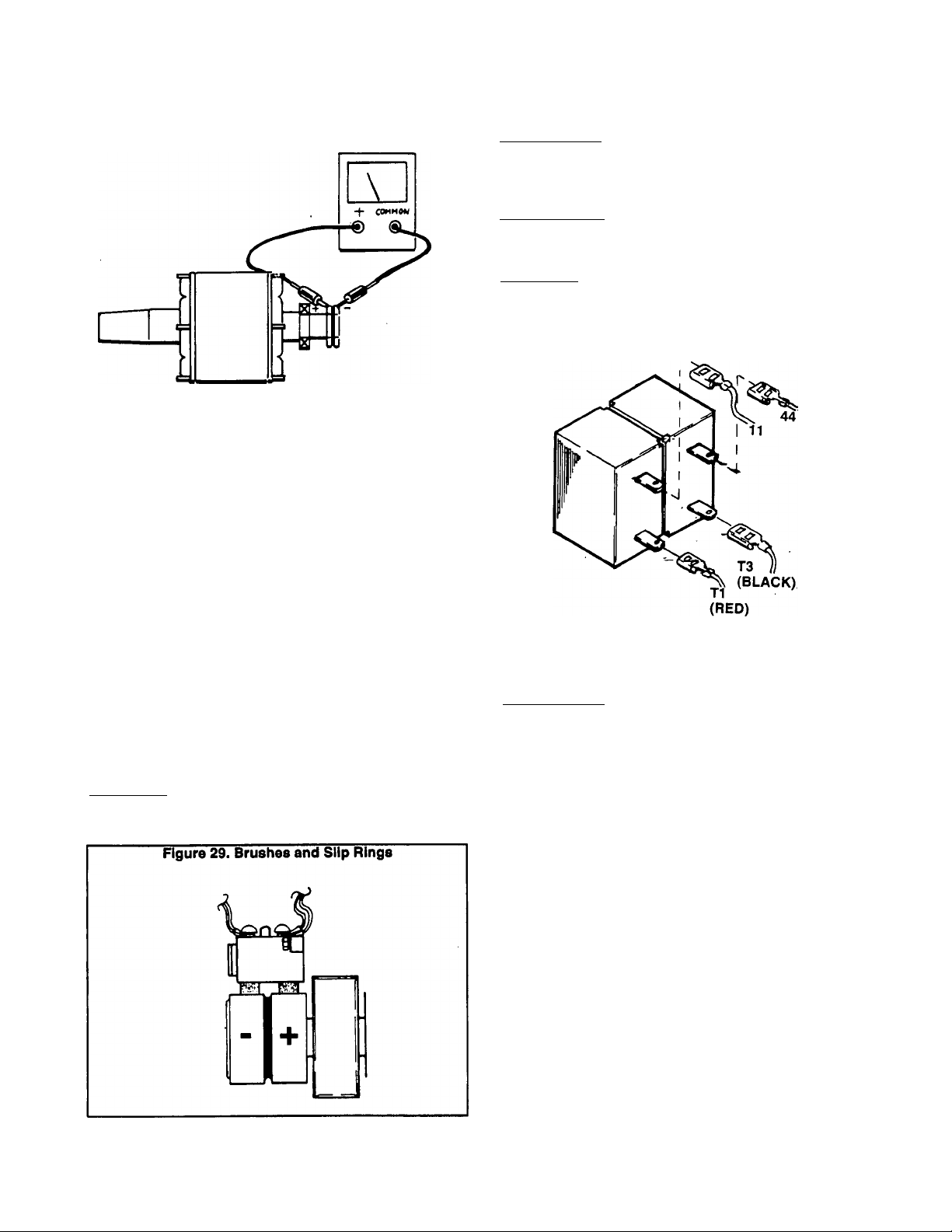
Figure 28. Checking Rotor Resistance
Test 9> Check Brushes and Slip Rings
DISCUSSION:
if the fixed (constant) excitation test did not result in an
AC output voitage of approximateiy one-haif rated voits, one
possibie cause of the probiem might be defective brushes
and/or slip rings.
Test 10- Test Main Circuit Breaker
DISCUSSION:
■ If AC output voltage and frequency are "zero", one pos
sible cause of the problem is an open or failed main circuit
breaker.
PROCEDURE:
Make sure the main circuit breaker Is set to Its ’Closed’
position, if the breaker Is closed, check it for continuity.
RESULTS:
1. Replace main circuit breaker. If It Is defective.
2. If main breaker is good, go to Test 11.
Figure 30. Main Circuit Breaker (Typical)
PROCEDURE:
Remove Wires 1 and 4 from the brushes. Then, remove
the brush holders from the rear bearing carrier. Inspect the
brushes and brush holders. Replace, It cracked, damaged,
worn excessively, etc.
Inspect the slip rings. If they are dull or tarnished, they
can be cleaned with fine sandpaper. DO NOT USE ANY
METALLIC GRIT TO CLEAN SLIP RINGS. Use low pressure
air (25 psi or less) to blow away cleaning residue.
Reassemble brushes and brush holders to rear bearing
carrier. Make sure brushes are properly seated in brush
holders and are contacting the slip rings properly. Reconnect
Wires 1 and 4 to brushes. Rotate the Rotor several times to
seat the brushes against the slip rings.
RESULTS:
Clean slip rings, replace bad brushes or brush holder(s)
as necessary.
Test 11- Check AC Power Lead Connec
tions
DISCUSSION:
The stator's AC output leads must be property connected
as outlined under ‘STATOR AC POWER CONNECTION
SYSTEMSr (Page 1.1-5).
PROCEDURE:
Check that Stator AC output leads 11,22,33 and 44 (as
well as T1, T2 and T3) are property connected as shown In
the appropriate wiring diagram/schematic. Reconnect wires
as necessary.
RESULTS:
Reconnect, repair or replace stator AC output leads as
necessary.
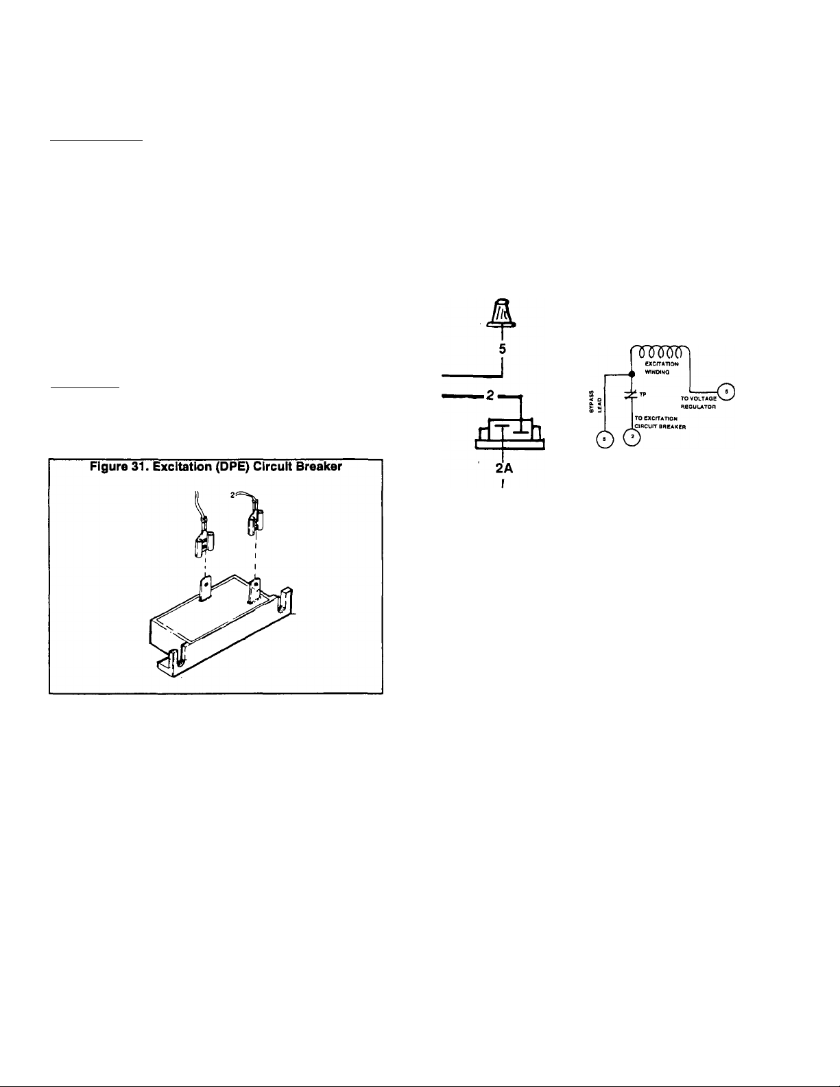
Test 12- Test DPE Circuit Breaker
DISCUSSION:
The excitation (DPE) circuit breaker is connected in
series with lead 2 (or 2A) between the stator excitation (DPE)
windings and the voltage regulator. If the breaker should
open, excitation winding AC output to the Regulator will be
lost and AC ou^ut from the generator will drop to a voltage
that is commensurate with the Rotor’s residual magnetism
(about 2 to 7 volts AC). Application of fixed excitation current
p est 6) will result in an AC output voltage equal to approxi
mately one-half rated voltage.
Page 1.6-3
Page 24
Test 12< Test DPE Circuit Breaker (Con
tinued)
PROCEDURE:
1. With the generator shut down, disconnect the leads from
the two breaker terminals, to prevent interaction. Then,
connect the test leads of a volt-ohm-milliammeter (VOM)
across the two circuit breaker terminals. The meter should
read continuity or a very small resistance.
a. If meter indicates 'continuity' or a small resistance, go
to Step 2.
b. If the meter reads 'infinity' replace the circuit breaker.
2. Reconnect the two leads to the circuit breaker terminals.
3. Start the generator engine.
4. Check the generator's AC output voltage (see Test 1).
a. if AC output voltage is excessively low, go to Step 5.
b. If AC output voltage is normal, discontinue tests.
5. Connect a jumper wire across the two terminals of the
excitation (DPE) circuit breaker. Again, check the unit’s AC
output voltage.
RESULTS:
1. In Step 1, if the meter reads 'infinity' it should be replaced.
2. If AC output voltage was excessively low in Step 4, but
normal in Step 5, replace the excitation (DPE) circuit breaker.
RESULTS:
1. If the VOM indicated excitation winding resistance in Step
4, but read 'infinity' in Step 6, the thermal protector will have
to be bypassed as follows:
a. Cut Wire 2 as close as possible to the end of Wire 5.
b. Strip the Insulation from the end of Wire 2 that goes to
the excitation circuit breaker.
c. Strip the iunsulation from the end of Wire 5.
d. Connect the stripped ends of Wire 2 and 5, retain with
the wire nut.
2. If the meter indicated excitation winding resistance In both
Steps 4 and 5, go to Test 14.
Figure 32. Thermal Protector In the Circuit
Test 13- Test Thermal Protector
DISCUSSION:
Also see 'THERMAL PROTECTOR' on Page 1.1-4. A
thermal protector that has failed open will cause the same
effects as an excitation circuit breaker that has failed open.
PROCEDURE:
1. Disconnect lead 2 from the excitation circuit breaker.
2. Disconnect lead 6 from the Voltage Regulator.
3. Locate lead 5. This lead is brought out of the Stator and is
unattached. A wire nut covers its end.
4. Connect the test leads of a VOM across leads 5 and 6. The
meter should read a small resistance (the resistance of the
Stator excitation winding).
5. Now, connect the VOM test leads across leads 2 and 6.
Again, the resistance of the Stator excitation windings shouid
be indicated (about 0.73 ohm for 10 kW units; 1.00 ohm for 8
kW units).
A. Pictorial
Figure 33. Thermal Protector Bypassed
B. Schematic
CXCrTATtON
rr*T)ON I
^ ^ WINDINO
-.-t
ÓO
TO EXCrTATION
2A
A. Pictorial
Test 14- Test Stator DPE Windings
DISCUSSION:
An open condition in the stator excitation windings wiii
result in loss of excitation output to the Voltage Regulator.
The Regulator will then shut down and generator AC output
voltage will drop to a value commensurate with Rotor residuai
magnetism (about 2-7 volts).
A grounded or shorted condition will also result in prob
lems with generator AC output. This test will test the Stator
excitation windings for (a) open condition, and (b) for a
grounded condition.
ClftClHT BBBAKER
B. Schematic
Page 1.6-4
Page 25

NOTE: Before attempting to test the Stator excitation
winding, be sure the thermal protector has not failed
open. See Teat 13.
PR^OCEDURE:
1. Disconnect Wire 2 from the excitation circuit breaker (CB4).
2. Disconnect Wire 6 from the Voltage Regulator.
3. Use a VOM to test the resistance of the excitation windings.
Connect the VOM test leads across leads 2 and 6. The VOM
should indicate the resistance of the excitation windings.
a. For 8 kW units, reading should be approximately 1.00
ohm (plus or minus 10%).
b. For 10 kW units, resistance should be approximately
0.73 ohm (plus or minus 10%).
4. Now, set the VOM to a high resistance scale such as
"Rxl 0,000’ or *Rx1 K’. Zero the meter. Connect one VOM test
lead to Wire 6, the other test iead to a clean frame ground on
the Stator. The meter should read 'Infinity'.
RESULTS:
1. If stator excitation windings fall the test, replace the Stator
assembly.
2. If excitation windings check good, go to Test 15.
Test 15- Test Stator AC Power Windings
DISCUSSION:
An open or shorted condition in the Stator will adversely
affect generator AC voltage output. This test will check the
AC power windings for (a) open condition, (b) grounded
condition, and (c) short between parallel windings.
PR^OCEDURE:
1. Disconnect and isolate Stator leads 11,22,33 and 44. Also
disconnect and isolate Stator leads 5 and 6.
2. Set a VOM to Its 'Rxl' scale and zero the meter.
3. Connect the VOM test leads across stator leads 11 and
22.
a. For 8 kW units, the meter should read approximately
0.21 ohm.
b. For 10 kW units, the VOM should indicate approximately
0.14 ohm.
NOTE: The actual realatance will vary slightly with tem
perature, with a nominal variation as much as plus or
mlnua 10 percent.
4. Connect the VOM test leads across stator leads 33 and 44.
Resistance readings should be the same as In Step 3(a) and
3(b).
5. Now, set the VOM to a high resistance scale, such as
’Rx10,000' or 'RxlK'. Zero the meter. Connect one meter
test lead to stator lead 11, the other test lead to stator lead
33.
a. The meter should read 'infinity'.
b. Any reading other than 'infinity' Indicates a short be
tween parallel windings.
6. With VOM still set for a high resistance, connect one VOM
test lead to stator lead 11, the other test lead to a clean frame
ground on the stator. Repeat the test with one test lead
attached to stator lead 33 and the other connected to a clean
frame ground on the stator.
a. The VOM should read '1011011/.
b. Any reading other than 'Infinity' Indicates a grounded
condition.
7. With the VOM still set for a high resistance, connect one
VOM test lead to stator lead 11, the other to stator lead 5.
Repeat the test with one VOM test lead connected to stator
lead 33, the other to stator lead 5.
a. In both cases, the meter should read 'Infinity'.
b. Any reading other than 'infinity' Indicates a short be
tween windings.
RESULTS:
1. If any reading is bad, replace the stator assembly.
2. If stator checks good, go to Test 16.
Test 16- Check Sensing Leads
DISCUSSION:
The Voltage Regulator must sense ACTUAL AC power
winding voltage. Itr must then electronically 'compare' the
ACTUAL voltage to a REFERENCE voltage that is preset In
the Regulator. The Regulator acts to maintain an actual
voltage that is the same as the reference voltage by regulat
ing excitation current flow to the Rotor.
If ACTUAL voltage sensing signals to the Regulator
become lost for any reason, the normal reaction of most
Regulators would be to think' that ACTUAL voltage Is too
low. The Regulator would then Increase excitation current
flow to the Rotor in an attempt to increase the ACTUAL
voltage. That is, the Regulator and Rotor would go to a 'Full
Field''^ condition and the generator’s AC output vdtage would
go to a very high maximum value.
However, the Voltage Regulator used on RV/IM models
is equipped with a 'sensing loss cutout' feature. That is, when
loss of sensing signals occurs, the Voltage Regulator will shut
down. When the Regulator shuts down, a complete loss of
excitation current flow to the Rotor will occur. The actual AC
output voltage will then drop dramatically to a value commen
surate with Rotor residual magnetism (about 2 to 7 volts AC).
PROCEDURE:
1. With the generator running, observe the red LED (light
emitting diode) on the AC voltage regulator. If sensing voltage
is available to the regulator, the light should be ON.
a. if the light is OUT, complete Step 2 below.
b. If the light is ON, go to Test 17.
2. Connect an accurate AC voltmeter across the Voltage
Regulator sensing terminals (leads 11 and 22). The meter
should Indicate line-to-neutrai voltage. If not, complete the
following:
a. Carefully Inspect sensina leads 11 and 22, between the
engine control circuit board and the Voltage Regulator.
b. Inspect leads 11 and 22 between the engine control
circuit board and the AC connection panel.
c. Use a VOM to check sensing leads 11 and 22 for an
open or shorted condition.
RESULTS:
1. Reconnect, repair or replace any damaged, open, shorted
or defective sensing leads.
2. If sensing leads are good, go to Test 17.
Test 17- Check Voltage Regulator
DISCUSSION:
The Voltage Regulator Is discussed under Test 16 above, as
well as on Page 1.1-4. The Regulator Is equipped with two
safety features, as follows:
Page 1.6<^
Page 26

Test 17- Check Voltage Regulator (Con
tinued)
1. Sensing loss shutdown- if sensing is not availabie to the
Regulator (sensing leads 11 and 22), the Regulator will shut
down.
a. With the Regulator shut down, loss of regulated excita
tion current to the Rotor will occur.
b. The generator’s AC output voltage will drop to a value
commensurate with Rotor residual magnetism (approxi
mately 2-7 volts AC).
c. The red LED (light emitting diode) on the Regulator is a
sensing indicator. The light will go OUT when sensing
signals to the Regulator (wires 11 and 22) are not avail
able. It should remain ON during operation, indicating that
sensing voltage is available.
2. Voltage limiting- maximum AC output voltage is limited to
a maximum of approximately 140-145 volts AC (llne-to-neutral).
PROCEDURE:
If a zero or low AC output voltage condition exists and
you have completed all previous tests Indicated in the Trou
bleshooting Flow Chart", you might try adjusting the Voltage
Regulator. If attempts to adjust the Regulator do not produce
positive results, replace the Regulator. Then, adjust the
Regulator and test generator operation.
Page 1.6-6
Page 27

Part 2
ENGINE
MECHANICAL
NP and IM Series
RECREATIONAL
VEHICLE &
INDUSTRIAL
MOBILE
AC GENERATORS
Liquid Cooled 1.2 Liter
Gas Engine Models
SECTION
2.1
2.2
2.3
2.4
2.5
2.6
TABLE OF CONTENTS
TITLE
Basic Engine Mechanical
Timing Belt
Cylinder Head
Oil Pan and Oil Pump
Oil Seal Replacement
Engine Overhaul
Page 28
Section 2.1- BASIC ENGINE MECHANICAL
This section covers some of the basic engine servicing
Introduction
tasks. Included In the Section are commonly used tightening
procedures for cylinder head bolts, manifold nuts and carbu
retor bolts. Also covered are valve clearance adjustment and
drive belt checking procedures.
Tightening Cylinder Head Boits
RetIghten cylinder head bolts while the engine Is cold, at
approximately 68* F. (20* C.). Tighten the bolts as follows:
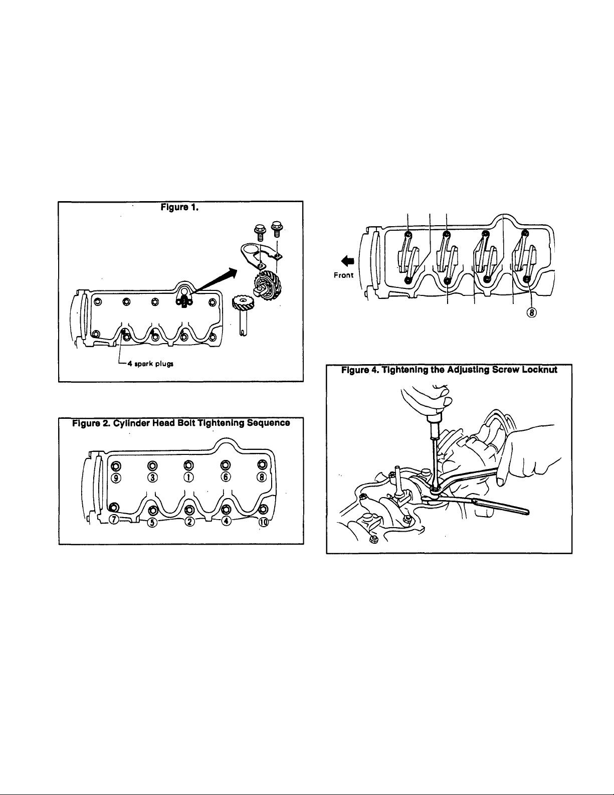
1. Remove all spark plugs, oil pump drive gears, retainer and
bolts (Figure 1).
1. Set No. 1 cylinder at top dead center (TDC) of Its compres
sion stroke. Then, adjust valve clearance 1,2,3 and 6.
2. Set No. 4 cylinder at top dead center (TDC) of its compres
sion stroke and adjust valve clearance 4, 5, 7 and 8.
3. Set valve clearance as follows:
VALVE CLEARANCE HOT
INTAKE s 0.010 Inch (0.25mm)
EXHAUST = 0.012 Inch (0.30mm)
Figure 3. Valve Clearance Adjustments
© (2) (?) (6)
(i) d) (z)
4. When valve clearances are properly set, tighten the adjust
ing screw locknut to 8-11 foot-pounds (11-15 N-m).
2. Tighten bolts to 47-51 foot-pounds (64-69 N-m) in the
sequence shown below.
Tighten Manifoid, Exhaust Manifoid and
Carburetor Fasteners
INTAKE MANIFOLD NUTS:
Tighten to 12-15 foot-pounds (16-21 N-m).
EXHAUST MANIFOLD NUTS:
Tighten to 12-15 foot-pounds (16-21 N-m).
CARBURETOR BOLTS:
Tighten to 4.3-5.8 foot-pounds (6-8 N-m).
Adjusting Vaive Clearance
Adjust valves while engine is warm, but not running, as
foltows:
Inspect drive belts for cracks, fraying, wear, ollllness.
Checking Drive Beits
Replace, if necessary. The belts should not touch the bottom
of the pulley groove. To check belt tension, apply a force of
approximately 22 pounds (10 kg) midway between pulleys.
Belt deflection should be as follows:
NEW BELT a 0.59^).75 inch (15-19m)
USED BELTaO.71-0.87 inch (18-22mm)
Measuring Compression Pressure
Warm up the engine. Then, shut down and remove ail spark
plugs. Use a standard automotive type compression gauge.
Hold the throttle and choke valves on carburetor wide open.
Page 2.1-1
Page 29
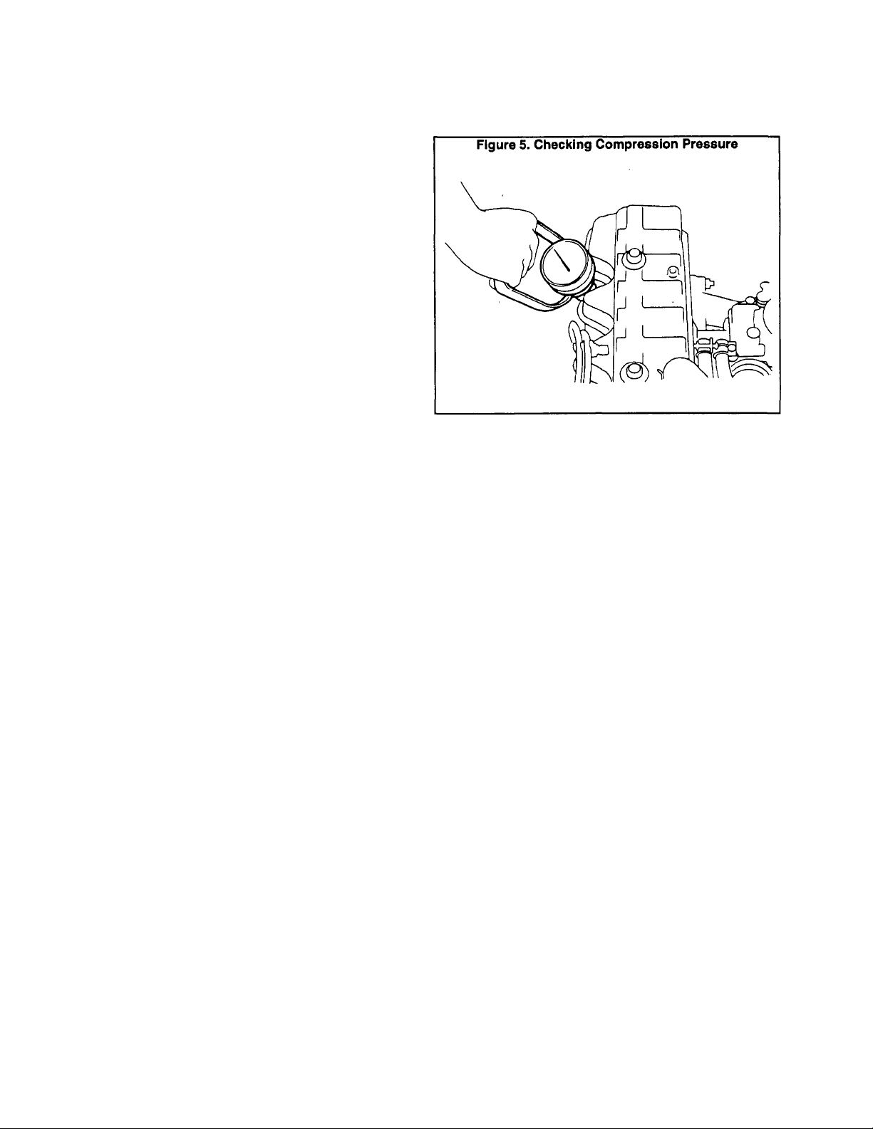
Measuring Compression Pressure (Continued)
then crank the engine and read the compression pres
sure. The pressure reading shouid be as follows:
^TANDAR^^^9278MiT5kg7clT?)at35^^
MINIMUM n 164 psi (11.5 kg/cm^) at 350 rpm
DIFFERENCE BETWEEN CYLINDERS SHOULD NOT
EXCEED 14 PSI (1.0 kg/cm^)
If the compression reading is low in any cylinder, pour a
small amount of clean engine oil into the cylinders through
the spark plug opening. Then, retest compression and eval
uate as follows:
D If compression pressure increased after adding the oil,
check for worn or damaged piston rings or worn cylinder
walls.
n If pressure did NOT increase after adding oil, valve(s)
may be sticking or seating improperly.
D If compression in any two adjacent cylinders is low and
adding oil did not increase compression, check for a
leaking head gasket
Page 2.1-2
Page 30
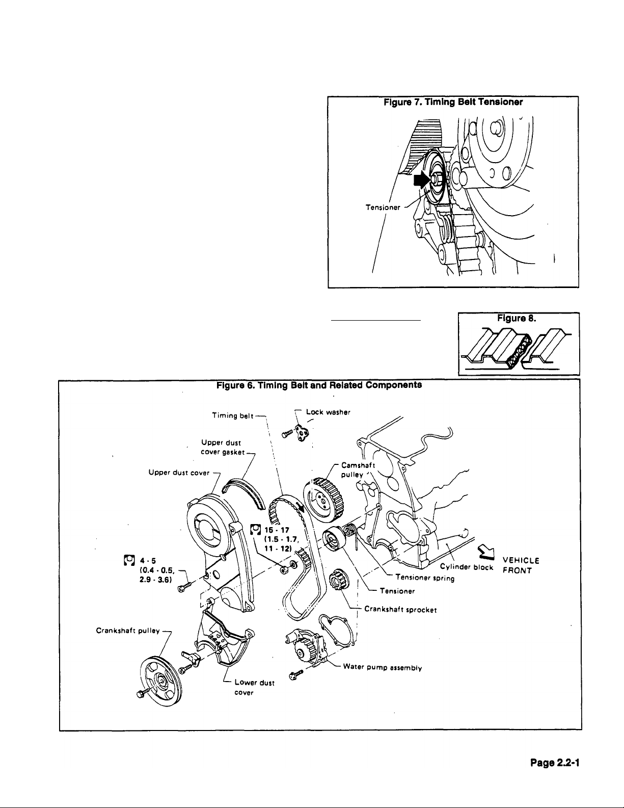
Section 2.2- TIMING BELT
Timing Belt Precautions
Comply with the following precautions when removing,
Installing or inspecting the timing belt:
D Make sure the timing belt, pullies and belt tensioner are
free of oil and water.
□ Prior to installing the timing belt, make sure that No. 1
cylinder is at top dead center (TDC) of its compression
stroke.
D Align the arrow on the timing belt in the direction of
engine rotation.
G Remove all spark plugs before adjusting timing belt
tension.
□ Once the timing belt has been removed, DO NOT rotate
the crankshaft and camshaft separately, or the valves
will strike the piston heads.
Q Do NOT bend or twist the timing belt too tightly.
Timing Beit Removai
1. Drain the radiator.
2. Remove the radiator, fan guard and fan. See Part 4,
“ENGINE COOLING SYSTEM".
3. Remove tension from the drive belt, then remove the drive
belt.
4. Remove the crankshaft pulley.
5. Set No. 1 cylinder at top dead center (TDC) of its compres
sion stroke. Then, remove upper and lower dust covers and
gaskets.
6. Loosen timing belt tensioner and return spring, then re
move timing belt.
Timing Beit Inspection
BELT IS BROKEN;
Caused by improper han
dling, poor belt cover sealing,
coolant leakage at water
pump.
Page 31

Timing Belt Inspection (Continued)
TOOTH BROKEN OR TOOTH ROOT CRACKED:
Caused by camshaft jamming,
distributor jamming, damaged
crankshaft or camshaft oil seal.
BACK SURFACE CRACKED OR WORN:
Caused by tensioner jamming,
overheated engine, interference with
belt cover.
SIDE SURFACE WORN:
Caused by Improper belt instal
lation, defective crank pulley and/or
timing belt plate.
CAUTION: The timing belt must be clean and free
of oil and water. Do NOT bend the belt. Arrow on
belt must point In normal direction of rotation.
Figure 14. Tensioner and Return Spring
NOTE: Replace the timing belt If (a) side surface Is worn
to such an extent that cutoff performed during the man
ufacturing process cannot be seen, (b) belt comers are
worn or rounded, or (c) belt fibers are frayed and coming
out.
BELT TEETH ARE WORN:
Caused by poor belt cover seal
ing, coolant leakage at water pump,
defective camshaft, defective distrib
utor, excessive belt tension. Some
problems that might be found under
Belt Teeth are Worn” include (a) can
vas on tooth face worn, (b) canvas on
tooth is fluffy, (c) rubber layer worn or
faded white, or (d) weft worn or invis
ible.
Timing Belt Installation
1. Check that No. 1 cylinder is at top dead center (TDC) of Its
compression stroke. Align the camshaft and crankshaft pulley
marks. See Figure 13.
2. See Figure 14. Install tensioner and return spring. Hook
the return spring to its stopper.
3. Slide the tensioner to the left and tighten the lock nut
temporarily (Figure 15).
4. Check that the water pump and tensioner pulleys can be
rotated smoothly and with no evidence of binding. Then,
install the timing belt.
Page 2.2-Z
Page 32

Timing Beit instaiiation (Continued)
5. Loosen the tensioner lock nut. With all spark plugs re
moved, rotate the camshaft pulley two full turns counterclock
wise. Tighten the tensioner lock nut.
6. Check belt tension. With a force of 1.06-1.28 pounds
applied, the belt should deflect about 0.08 Inch (2mm).
7. Tighten the tensioner lock nut to 11-12 foot-pounds (15-17
N-m).
Page 33

Section 2.3- CYLINDER HEAD
Cylinder Head Removal
1. Remove timing belt (Section 2.2). Then, remove OIL PUMP
IDLER GEAR.
Figure 21. Remove Valve Component Parts
2. Remove the cylinder head. Loosen bolts in 2 or 3 stages,
in the sequence shown above.
screwdriver.
4. Remove the Camshaft (Figure 20).
5. Remove valve components parts (Figure 21).
6. Use a suitable puller to remove valve oil seals (Figure 22).
Checking Cylinder Head Distortion
Use a thickness gauge and a straightedge to measure
cylinder head distortion. See Figure 23 (next page). Lay the
straightedge across the cylinder head surface as shown.
Surface warpage must not exceed 0.004 inch (0.1 mm). If the
cylinder head exceeds the stated value, it must be replaced.
Resurfacing Limit: The amount of resurfacing that can be
done on the cylinder head depends on the amount of resur
facing on the cylinder block. If the amount of HEAD surfacing
is "A^and the amount of BLOCK surfacing is "B“, the maxi
mum limit is as follows:
Page 2.3-1
Page 34

Checking Cylinder Head Distortion (Con
tinued)
Use a suitable dial indicator to measure valve stem to
Valve Guide Clearance
guide clearance. The valve should be moved parallel to the
rocker arm, since most of the wear occurs in this direction.
See Figure 24.
Figure 24. Valve Guide Clearance
Stem to guide clearance:
Maximum limit
0.10 mm (0.0039 in)
Max. allowable deflection
(Dial indicator readirrgi
0.2 mm (0.008 in)
Valve Guide Replacement
If valve guides must be replaced, proceed as follows:
1. Heat the cylinder head to 302‘-320‘ F. (150‘-160' C.) in an
oil bath (Figure 25).
2. Use a press exerting a 2.2 U.S. ton (20 kN) force to remove
valve guides. If a press is not available, use a hammer and a
suitabfe driving tool (Figure 26).
3. Ream the cylinder head's valve guide hole (Figure 27).
Page 2.3-2
Page 35

5. Ream the valve guides to a finished size of 0.2758-0.,2764
inch (7.005-7.020mm).
Camshaft Bearing Clearance
Check camshaft bearing clearance (Figure 31). Check
both the bore and the bearing outside diameter (O.D.). The
difference between the two measurements is the bearing
clearance. Maximum bearing clearance is shown below:
MAXIMUM CAMSHAFT BEARING CLEARANCE
0.0059 Inch (0.15mm)
Inspect valve inserts for evidence of pitting at valve
Valve Inserts
contact surfaces. Reseat or replace, if worn or pitted exces
sively. The following rules apply:
D When repairing valve inserts, first check the valve and
valve guide for wear. If worn, replace them. Then, correct
the valve seat.
□ When cutting, use both hands for more uniform cutting.
Figure 30.
Use a suitable measuring device to check camshaft
runout (Figure 33).
If necessary, replace valve inserts as follows:
1. Ream the cylinder head recess.
2. Heat the cylinder head to 302‘-320’ F. (150'-160‘ C.).
3. Install the insert. Make sure it bends at bottom face of its
recess and caulk at more than 4 places.
4. Use a suitable tool to grind newly fitted valve seats. Grind
the seats to the specifications listed in the applicable SPEC
IFICATIONS chart.
5. Apply a small amount of valve grinding compound to the
valve contacting face and place valve into guide.
Page 2.3-3
Page 36
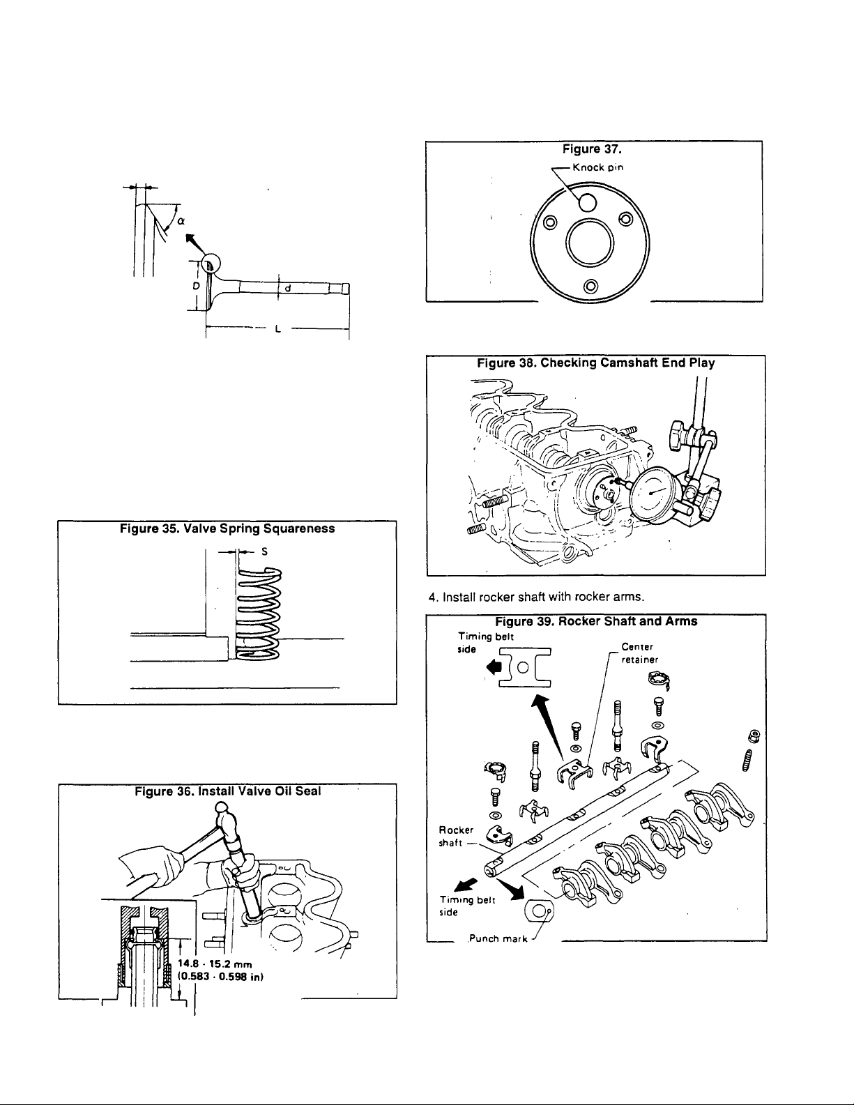
Check dimensions of all valves. Refer to the appropriate
Valve Dimensions
SPECIFICATIONS chart.
Figure 34. Valve Dimensions
T (Margin thickness!
NOTE: When the valve head Is worn to 0.020Inch (0.5mm)
margin thickness, replace the valve. Grinding allowance
for valve stem end surface Is 0.008 Inch (0.2mm) or less.
Valve Spring Squareness, Free Length
and Tension
Valve spring out-of-squareness must not exceed 0.079
inch (2.0mm). Refer to appropriate SPECIFICATIONS chart
for spring free length and tension.
2. Install camshaft assembly. Note positioning of camshaft
front face when No. 1 cylinder is at top dead center (TDC) of
its compression stroke.
3. Measure camshaft end play with thermostat housing and
gasket installed.
1. Install valve oil seal. Then, install valve component parts.
Cylinder Head Assembly
Apply engine oil to camshaft oil seal and install the seal.
Page 2.3-4
5. Install bolt stoppers. Always use NEV\/ bolt stoppers. See
Figure 40, next page.
Page 37
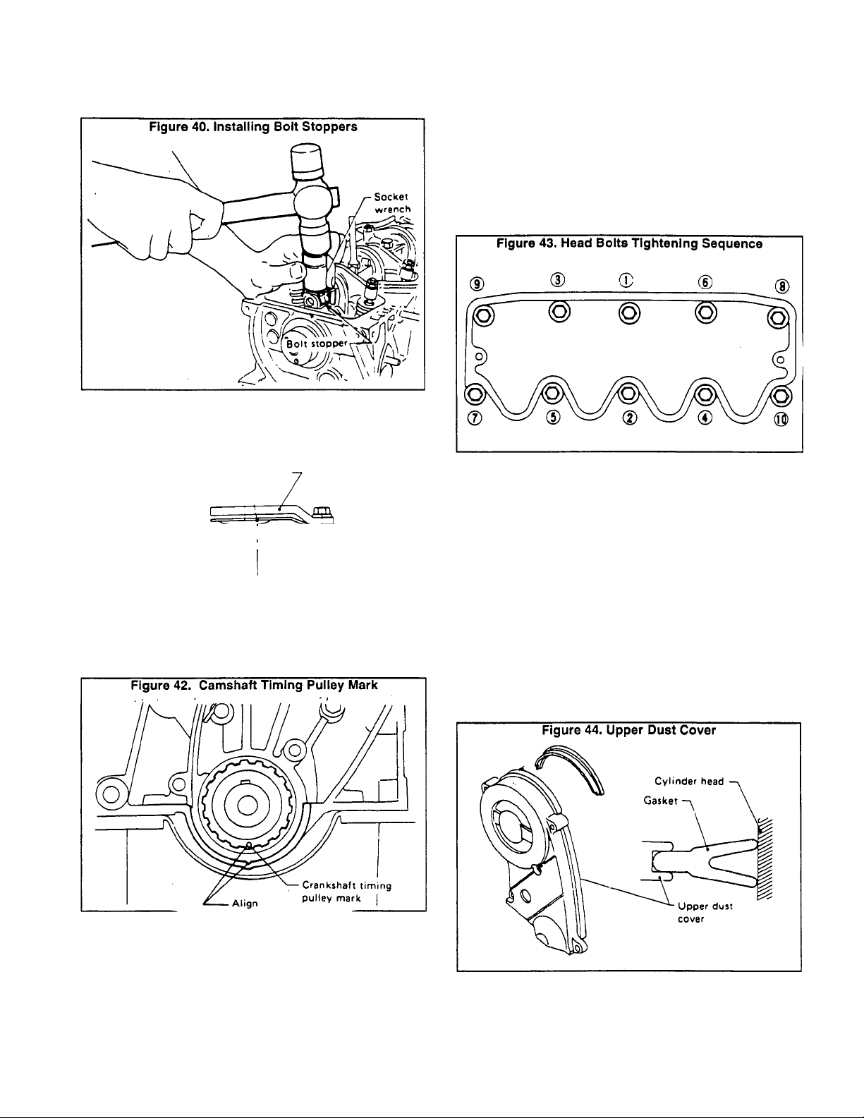
Cylinder Head Assembly (Continued)
6. Install oil pump Idler gear and oil pump regulator spring.
Make sure the spring faces in the proper direction.
Figure 41.
Oil pump spring stopper
Oil pump regulator spring ^
dJ
Oil pump drive gear
Installation
1. Set No. 1 cylinder head at top dead center (TDC) of its
compression stroke by first aligning the CAMSHAFTTIMING
PULLEY MARK with mark on the main bearing cap.
2. Install cylinder head with a new gasket. The following rules
apply:
D Always use a new cylinder head gasket.
D Before tightening the cylinder head bolts, check that the
oil pump drive gear can be turned freely by hand.
D Always installwashers between bolts and head.
D Tighten cylinder head bolts in the sequence shown in
Figure 43.
3. Tighten cylinder head bolts as follows:
a. First, tighten all bolts to 22 foot-pounds (29 N-m).
b. Then, tighten all bolts to 47 foot-pounds (64 N-m).
c. Loosen all bolts completely.
d. Tighten all bolts to 22 foot-pounds (29 N-m).
e. Tighten all bolts to 47-51 foot-pounds (64-69 N-m).
NOTE: When RETORQUING cylinder head bolts for nor
mal periodic maintenance, first loosen all bolts slightly.
Then (with engine COLD), tighten all bolts In correct
sequence to 47-51 foot-pounds (64-69 N-m).
4. Install timing belt. Install oil pump Idler and oil pump
regulator spring (make sure spring direction is correct). Install
upper dust cover, making sure its gasket mates with cylinder
head properly.
CAUTION: DO NOT rotate crankshaft and cam
shaft separately or valves will hit the piston heads.
Page 2.3-5
Page 38

Installation (Continued)
5. Tighten upper dust cover bolts to 2.9-3.6 foot-pounds
(4-5 N-m) (Figure 45).
6. Instail spark plugs and tighten to 14-22 foot-pounds
(20-29 N-m).
Figure 45A. Engine Cylinder Head Assembiy
Figure 45. Tighten Dust Cover Bolts
Oil pump
Spring itopptr *
Oil pump regulator spring .
8# careful of its direction.
Rocker —^0
pivot
retainer
<S>
Rocker shaft
Be sure to align rocker
shaft front mark to
timing belt side.
Page 2.3-6
Whtn inttalling tliding parti su eh ai
bearìngs, ba su re to appiy angina oil
on tha iliding lurfacai.
Usa naw gaikati and oil laaii.
Whan inrtallirtg walch plug. apply
saaiant.
Camshaft oil seal '
intake valve insert -
Exhaust valve insert -
Cylinder head gasket
Page 39

Section 2.4- OIL PAN AND OIL PUMP
Drain engine oil. Then, remove oil pump assembly with
oil strainer. BE CAREFUL NOT TO DROP THE OIL PUMP
DRIVE SHAFT.
Inspection
Oil Pump Removal
Refer to Part 3, ‘ENGINE LUBRICATION SYSTEM'.
Installation
1. Install the oil pump assembly and tighten to 13-16 foot
pounds (18-22 N-m).
CAUTION: Before tightening the oil pump assem
bly, rotate the oil pump drive gear to make sure
that the pump drive shaft does not interfere with
inner wall of cylinder block.
2. Apply RTV gasket sealant to oil pan as shown in Figure 47.
3. Install oil seals. Apply RTV sealant to upper and lower
surfaces of gaskets as shown (Figure 48).
4. Install gaskets and oil pan. Tighten bolts to 2.9-3.6 foot
pounds (4-5 N-m).
__________________________
Figure 47. Apply RTV Gasket Sealant
Apply sealant
Page 2.4-1
Page 40
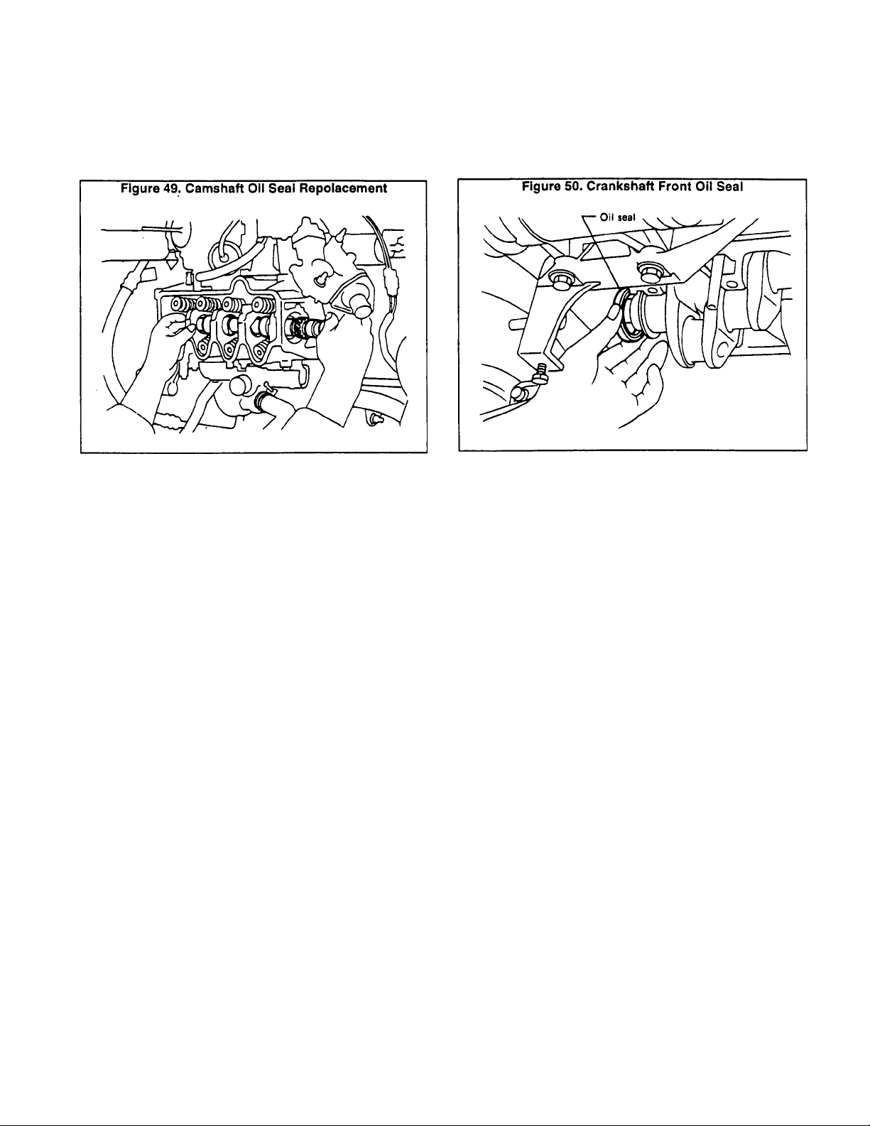
Section 2.5- OIL SEAL REPLACEMENT
Camshaft Oil Seal Replacementjpi
Remove timing belot, oil pump idler gear. Remove bolt
stoppers and rocker shaft with rocker arms. Remove cam
shaft. Remove camshaft oil seal. Apply engine oii to new
camshaft oil seal and install.
dler
Crankshaft Front Oil Seal Replacement
Remove Timing Belt and Cover. Remove oil pan. Re
move main bearing caps. Remove crankshaft oii seai. Appiy
engine oil to new crankshaft front oil seal and install.
Page 2.5-1
Page 41

Section 2.6- ENGINE OVERHAUL
1. Place engine on workstand. Remove timing belt cover and
Disassembly
timing belt Remove cylinder head and oil pan. Remove
pistons.
2. Remove crankshaft rear oil seal retainer. Remove bearing
caps. Remove the crankshaft.
RING TO GROOVE SIDE CLEARANCE
MAXIMUM LIMIT
Гор Ring = 0.0016-0.0029 inch (0.040-0.073mm)
2nd Ring = 0.0012-0.0025 inch (0.030-0.063mm)
Maximum
Tolerance=0.008 inch (0.2mrh)
Figure 53. Checking Piston Pin Fit
1. Slide piston pin into piston'pin bore. At room temperature,
Inspection
pin must slide smoothly into bore, without side play and
without binding. See Figure 53.
PISTON PIN TO PISTON CLEARANCE
0.0003*0.0005 Inch (0.008-0.012mm)
2. Check piston ring to groove side clearance (Figure 54).
Clearance should not exceed the maximum stated limit
TOP RING
No. 1 Grades 0.0083-0.0118 Inch (0.21-0.30mm)
No. 2 Grades 0.0071-0.0118 Inch (0.18-0.30mm)
No. 3 Grades 0.0071-0.0118 inch (0.18-0.30mm)
2ND RINGS 0.0059-0.0154 Inch (0.15-0.39mm)
OIL RINGS 0.0079-0.0311 inch (0.20-0.79mm)
4. Use Plastigage" to check bearing clearance (Figure 56).
Comply with the following:
Page 2.6-1
Page 42
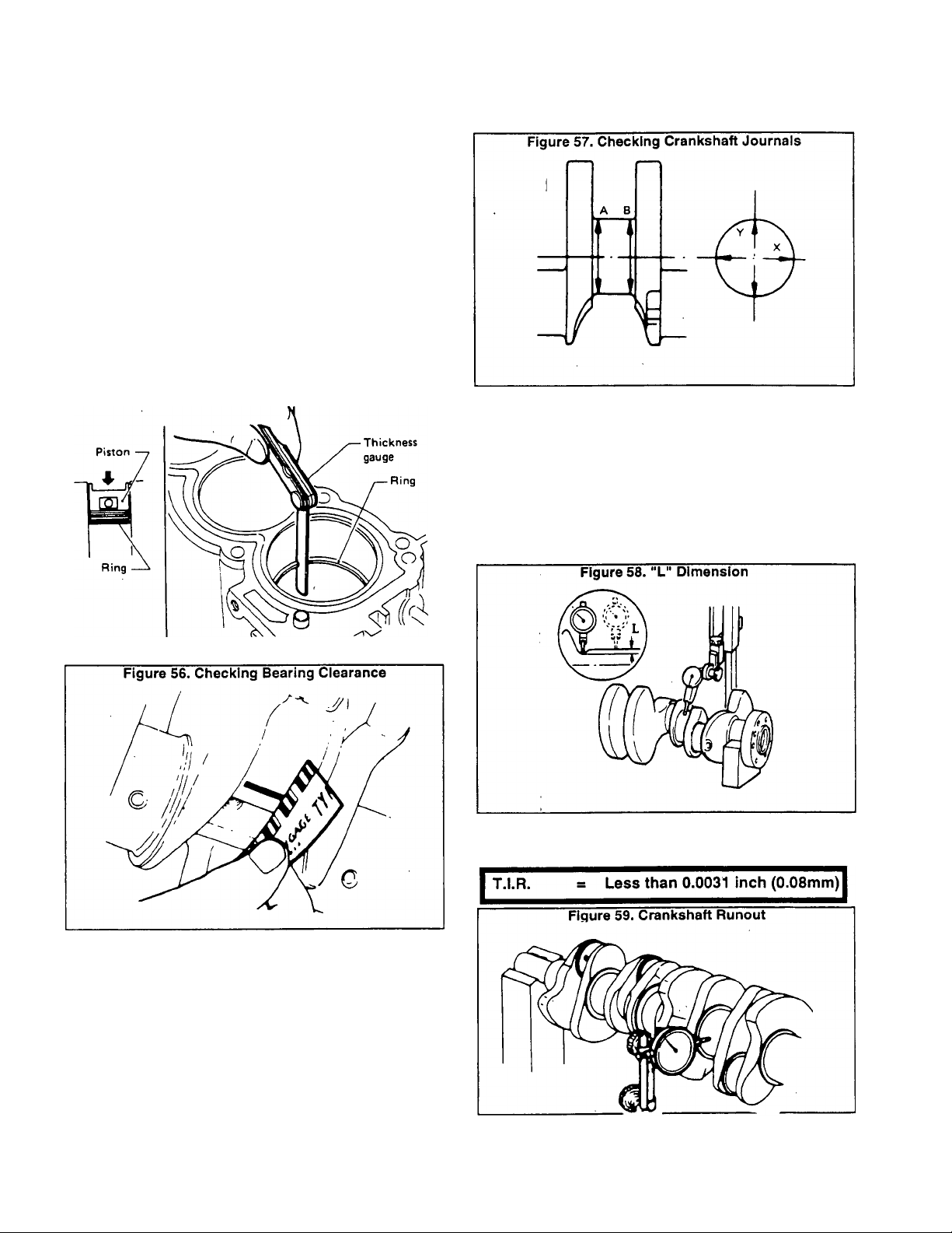
Inspection (Continued)
a. DO NOT turn the crankshaft or connecting rod when
Plastigage^ is being inserted.
b. When bearing clearance exceeds the specified limit,
check that the correct bearing has been installed. If exces
sive clearance still exists, use a thicker main bearing or an
undersize bearing to obtain correct clearance.
BEARING CLEARANCE
Main Bearing= 0.0012-0.0020 Inch (0.03-0.05mm)
Limit = 0.0030 inch (0.075mm)
Connecting
Rod Bearing= 0.0008-0.0024 Inch (0.02-0.06mm)
Limit = 0.0047 inch (0.12mm)
Figure 55. Checking Ring Gap
6. When regrinding crankpin journal, measure the “L° dimen
sion in the fillet roll (Figure 58). The measured value must
exceed the specified limit. If measurements are within the
specified limit, DO NOT regrind.
NOTE: DO NOT grind off the fillet roll. Refer to applicable
SPECIFICATIONS chart for regrlndlng crankshaft and
available service parts.
5. Inspect crankshaft journals for scoring, bias, wear or
cracks. Minor defects can be corrected using fine crocus
cloth. Use a micrometer to check journals for taper and
out-of-round. See Figure 57.
Out-of-Round (X-Y) = 0.0004 Inch (0.01mm)
Taper (A-B) = Less than 0.0008 inch (0.02mm)
Page 2.6-2
7. Check crankshaft runout. “T.I.R." stands for "Total
Indicator Reading".
Page 43

8. Surface warpage must be less than 0.004 inch (0.1mm). If
beyond the specified limit, resurface the cylinder block. Re
surfacing limit of the cylinder block is determined by the
amount of resurfacing done on the cylinder head. If the
amount of resurfacing on the cylinder head is “A" and the
resurfacing on the cylinder block is "B‘, the maximum limit is
as
I A + B = 0.008 inch (0.2mm) I
CAUTION: When resurfacing, use care not to cut
off the punched piston grade number.________________
10. Use a micrometer to measure the piston skirt diameter
(Figure 61). The measuring point for checking piston skirt
diameter is 0.35 inch (9mm) as shown in Figure 63 (Point “L").
STANDARD PISTON SKIRT DIAMETER
2.6759-2.6770 inch (67.967-67.997mm)
Piston clearance must be within the stated specifica-
tions.
PiSTON CLEARANCE
0.0009-0.0017 inch (0.023-0.043 mm)
9. Use a bore gauge to measure the cylinder bore for wear,
taper or out-of-round. Inspect for scratches or seizure. Hone
the bore as necessary.
STANDARD INSIDE DIAMETER
2.7953-2.7965 inch (71.00-71.03mm)
OUT-OF-ROUND (X-Y) LIMIT
0.0008 inch (0.02mm)
TAPER (A-B) LIMIT
0.0008 inch (0.02mm)
11. To measure piston clearance, use a 0.0016 inch
(0.04mm) feeler gauge, inserted between the piston and the
cylinder bore (Figure 64). The force required to remove the
feeler gauge should be as follows:
REMOVAL FORCE
1.1-3.3 pounds (0.5-1.5kg)
12. Check flywheel runout (Figure 65). Total indicator reading
(T.I.R.) should be less than the value specified below.
T.I.R. RUNOUT
Less than 0.0059 inch (0.15mm)
Page 2.6-3
Page 44

Inspection (Continued)
Each crankshaft has stamped numbers which indicate
main journal dimensions. Each journal is measured sepa
rately.
Select the correct main bearing thickness and order from
the parts breakdown.
Figure 66. Piston Pin Installation
Numbers that correspond to the cylinder number are
stamped on connecting rods and connecting rod caps. Pis
tons, connecting rods, connecting rod caps and bearings
should be installed only in the correct cylinder. DO NOT
COMBINE PARTS FROM DIFFERENT CYLINDERS. When
pressing the piston pin into the connecting rod (Figure 66),
apply oil to the pin and to small end of connecting rod.
CRANKSHAFT:
Place main bearings in their proper position on the
cylinder block. If the crankshaft, cylinder block and main
bearings are to be replaced, you must select proper main
bearing thicknesses.
When either the crankshaft, cylinder block or main bear
ings are to be re-used, it is necessary to measure main
bearing thickness with Plastigage".
Numbers are stamped on the engine which indicate
cylinder block main journal. Measure each bore separately.
Page 2.6-4
Page 45
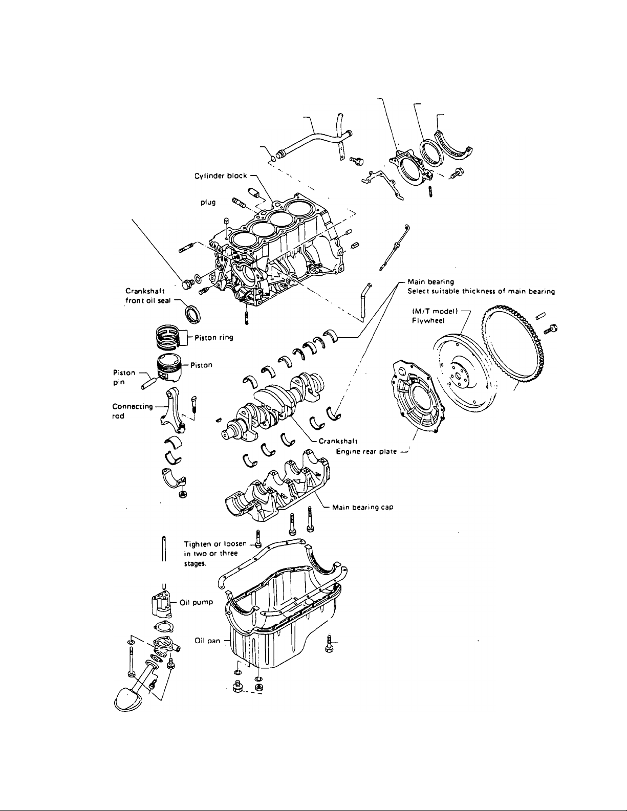
Cylinder Block, Crankshaft and Piston
Apply soaping water to 0-ring.
Apply sealant to threads of
and surfaces of gasket.
Water pump suction pipe
Rear oil seal retainer
Crankshaft rear oil seal
Engine rear
rubber
Oil pump drive —
shaft
Ring gear
m
Page 2.6-5
Page 46
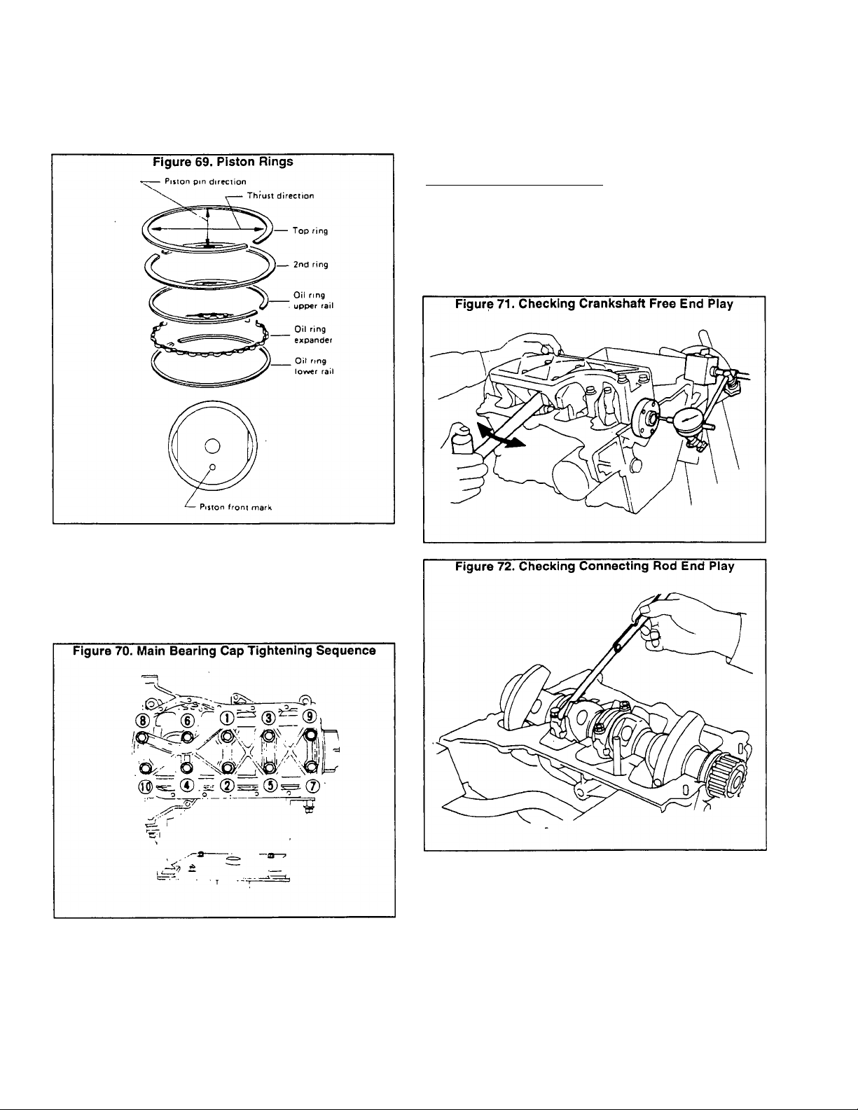
Assembly (Continued)
INSTALL PISTON
1. Install piston rings as shown in Figure 69.
STON ASSEMBLY:
CRANKSHAFT FREE END PLAY
End Play = 0.0024-0.0087 inch (0.06-0.22mm)
Wear Limit = 0.0197 inch (0.50mm)
CONNECTING ROD END PLAY:
Connecting rod end play should be within the following limits;
CONNECTING ROD END PLAY
0.0039-0.0146 inch (0.10-0.37mm)
MAIN BEARING CAPS:
Install main bearing caps and tighten bolts to 34-38 foot
pounds (46-52 N-m). Tighten the caps in 2 or 3 stages and in
the sequence shown in Figure 70. Before tightening the
bearing cap bolts, place caps in proper position by shifting
the crankshaft axially. After tightening the berating cap bolts,
check that the crankshaft turns smoothly by hand.
CRANKSHAFT FREE END PLAY:
Measure crankshaft free end play at the center bearing
(Figure 71). Nominal end play and wear limit are as follows:
Page 2.6-6
Page 47

Part 3
ENGINE
LUBRICATION
SYSTEM
NP and IM Series
RECREATIONAL
VEHICLE &
INDUSTRIAL
MOBILE
TABLE OF CONTENTS
SECTION
3.1 Lubrication System Familiarization
3.2
TITLE
Engine Oil Pump
AC GENERATORS
Liquid Cooled 1.2 Liter
Gas Engine Models
Page 48

Section 3.1- LUBRICATION SYSTEM FAMILIARIZATION
Engine Lubrication Circuit
Figure 1, below, shows the engine lubrication circuit in
block diagram form and pictorially.
Use a high quality detergent oil classified "For Service
SC, SD, SE or SF". Detergent oils keep the engine cleaner
and reduce carbon deposits. Use oil having the viscosity
rating listed in the chart below, based on the ambient temper
ature range anticipated before the next oil change.
TEMPERATURE
Above 86' F.
32' to 85* F.
Below 32* F.
All Seasons
OIL GRADE
Use SAE 40 oil
Use SAE 30 oil
Use SAE 20W oil
UseSAE10W-30oll
Low Oil Pressure Shutdown
The engine is equipped with a low oil pressure switch,
which is exposed to oil pressure in the engine's main oil
gallery. The pressure switch contacts are normally-closed
(N.C.), but are held open by oil pressure during startup and
running conditions. Should oil pressure drop below approxi
mately 12-15 psi, the switch contacts will close and an auto
matic engine shutdown will occur.
Figure 1. Engine Lubrication Circuit
Recommended Oils
Checking Low Oil Pressure Shutdown
To test the operation of low oil pressure shutdown, start
the engine. Let the engine run at no-load, i.e., with all electri
cal loads disconnected from the generator. Disconnect wire
from oil pressure switch terminal and hold the wire terminal
end against a clean frame ground on the engine. After a very
short delay, the engine should shut down.
0<i ••»•nr evi'i
■ Bt-mu MM«»
A. Biock Diagram
B. Pictoriai
Page 3.1-1
Page 49

Warm up the engine. Then, shut down and remove the
Oil Pressure Check
oil pressure switch, install a direct reading pressure gauge in
the oil pressure switch port..,Start the engine and check oil
pressure with the engine running at no-load condition, i.e., no
electrical loads connected to generator.
Oil Pressgre reading should be approximately 40-46 psi
(2.8-3.2 kg/cm^) at 1860 rpm.
Page 3.1-2
Page 50

Section 3.2- ENGINE OIL PUMP
Oil Pump Disassembly
When removing the oil pump, be careful not to drop the
oil pump drive shaft. When installing the pump, apply engine
oil to the drive gear and shaft. The inner rotor and shaft cannot
be disassembled.
Oil Pump Inspection
Visually inspect oil pump parts for wear and damage.
Inspect the oil pressure regulator valve sliding surfaces and
valve spring. Replace the valve seat, if damaged. Use a feeler
gauge to check (a) rotor tip clearance, (b) outer body to body
clearance, and rotor to straight edge clearance. See Figure
5.
Page 51

Oil Pump Inspection (Continued)
ROTOR TIP CLEARANCE
Less than 0.008 inch (0.2mm)
OUTER ROTOR TO BODY CLEARANCE
Less than 0.008 inch (0.2mm)
ROTOR TO STRAIGHT EDGE CLEARANCE
Less than 0.008 inch (0.2mm)
Page 3.2-2
Page 52

Part 4
ENGINE
SECTION
4.1
4.2
4.3
FABLE OF CONTENTS
TITLE
Cooling System Familiarization
Water Pump and Thermostat
Cooling and Ventilating Air
COOLING
SYSTEM
NP and IM Series
RECREATIONAL
VEHICLE &
INDUSTRIAL
MOBILE
AC GENERA
TORS
Liquid Cooled 1.2 Liter
Gas Engine Modeis
4.4
4.5 Optional Heat Recovery System
Optionai Remote Radiator Fan
Page 53
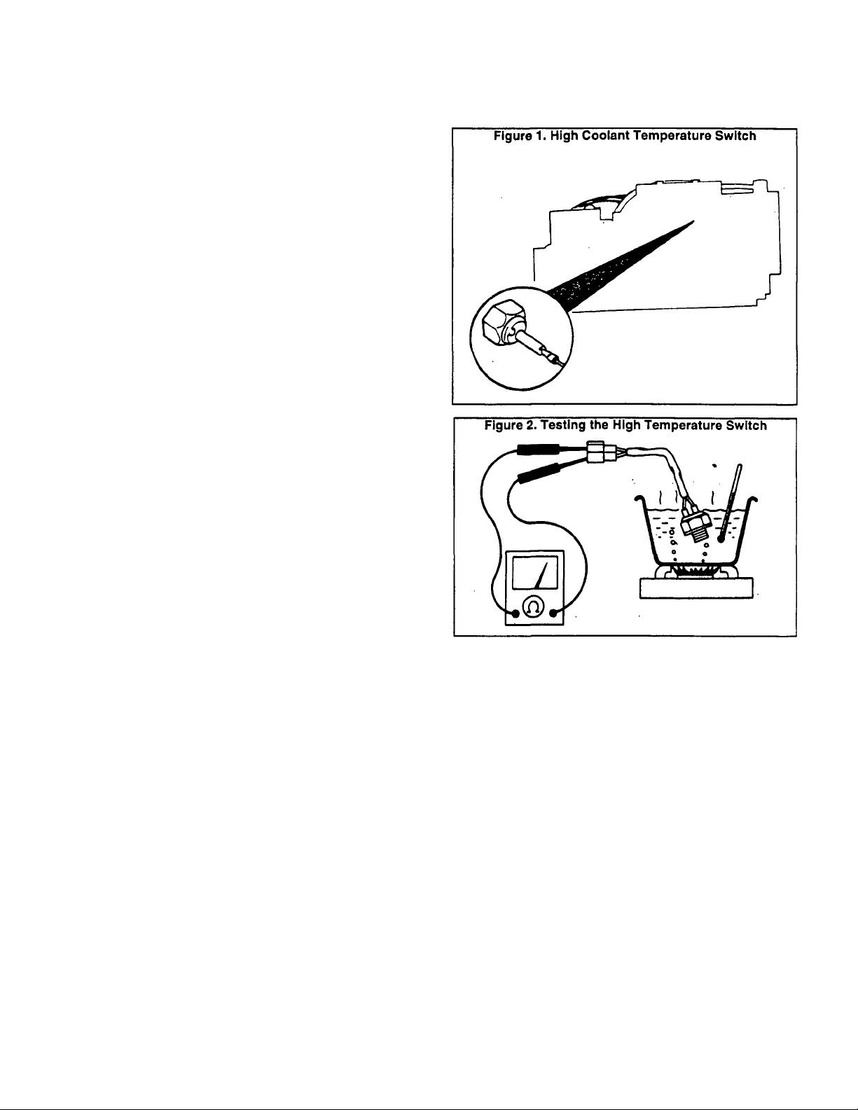
Section 4.1- COOLING SYSTEM FAMILIARIZATION
The generator cooling system is of the closed recovery
Introduction
type. Major cooling system components consist of (a) radia
tor, (b) coolino fan, (c) coolant recovery bottle, (d) engine
water pump, (e) thermostat, and (f) interconnecting hoses.
Recreational vehicle generators are typically housed in
a compartment. An adequate flow of cooling, combustion and
ventilating air must be provided for these compartments.
Some models are equipped with unit-mounted radiators.
Other models may have remote mounted radiators.
At least one IM (Industrial Mobile) generator model is
equipped with a heat recovery system.
Recommended Coolant
Recommended Is a 50-50 mixture of low silicate ethylene
glycol base anti-freeze and soft water for all-weather protec
tion. If desired, a high quality rust inhibitor may be added to
the recommended mixture. When adding coolant to the radi
ator or to the coolant r4ecovery bottle, always add the recom
mended 50-50 mixture.
NOTE: Cooling system capacity for models with unitmounted radiator Is approximately 2.5 U.S. gallons (9.5
liters). Use only SOFT water and LOW SILICATE anti
freeze. For Installations equipped with a remote-mounted
radiator, cooling system capacity will depend on radiator
hose lengths.
CAUTION: The use of any "chromate" base Inhib
itor is NOT recommended. When chromate base
rust inhibitor is used with ethylene glycol base
anti-freeze, chromium hydroxide Is formed in the
cooling system. Chromium hydroxide Is visible to
the eye as a "green slime" which can cause re
duced heat transfer and possible overheating. Any
cooling system that has been operated with a
chromate base inhibitor must be chemically
cleaned before adding ethylene glycol base anti
freeze. Use of any high silicate anti-freeze boost
ers or additives is NOT recommended. In addition
to the preceding, the use of any soluble oil rust
inhibitor Is NOT recommended.
The switch contacts should close and switch should read
“continuity“ at about 225‘-235’ F. (107'-113‘ C.).
High Coolant Temperature Switch
DESCRIPTION:
The engine mounts a normally-open (N.O.) thermostatic
switch (Figure 1). The sensing tip of the switch is normally
immersed in engine water jacket coolant. Should coolant
temperature exceed approximately 230' F. (110* C.), the
switch contacts will close and the engine will shut down
automatically.
TESTING HIGH TEMPERATURE SHUTDOWN:
To test the high temperature shutdown feature, first
disconnect Wire No. 85 from the switch terminal. Start the
engine, let it stabilize and warm up at no-load. Hold the
terminal end of Wire No. 85 into contact with a clean frame
ground on the engine. After a short delay, the engine should
shut down.
TESTING THE SWITCH:
Remove the switch. Check the switch closing tempera
ture with an ohmmeter (Figure 2).
Page 4,1-1
Page 54
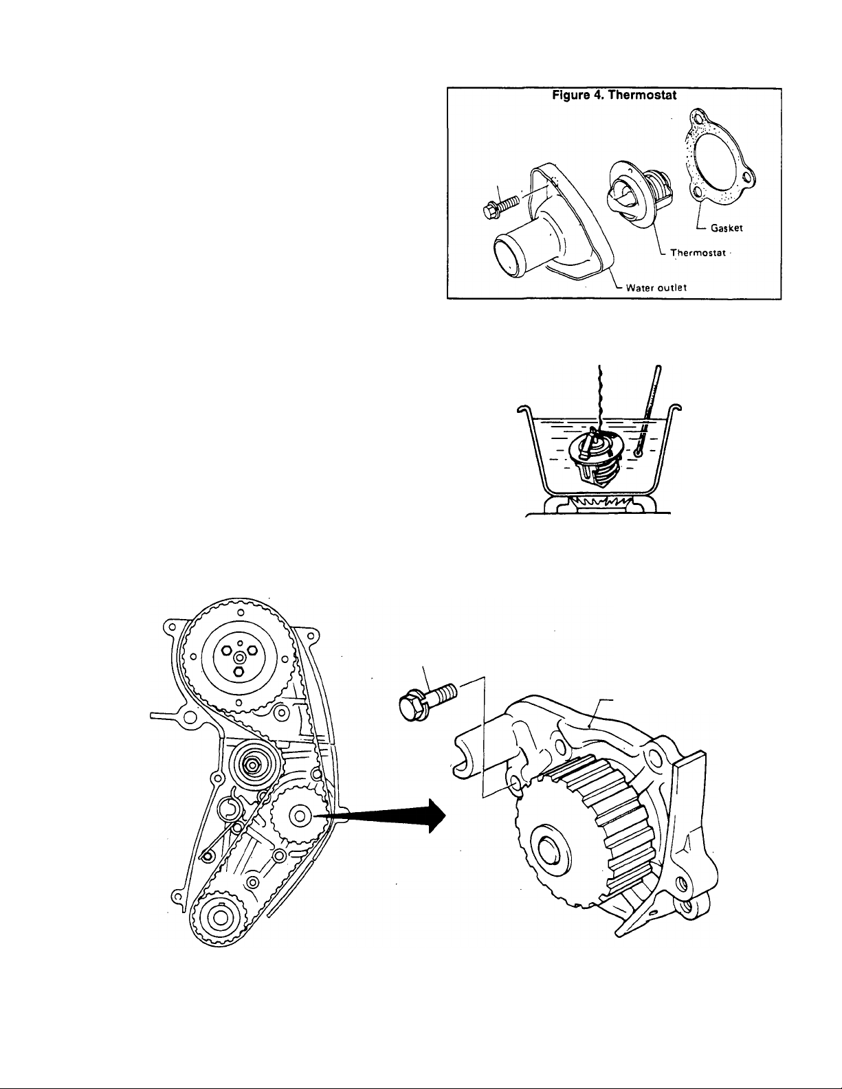
Section 4.2- WATER PUMP AND THERMOSTAT
The engine water pump (Figure 3) cannot be disassem-
Water Pump
bied and must be replaced as a unit. Check the [pump for
excessive end play and smoothness of rotation. Bolt holes
are drilled through the water jacket in the cylinder block. Use
a sealant and tighten the bolts to the recommended torque.
After installation, operate the engine and check for leaks.
Thermostat
Check the thermostat for proper seating at ambient tem
perature. It should seat tightly. Check its opening tempertature and lift.
VALVE OPENING TEMPERATURE
190* F. (88* C.)
MAXIMUM VALVE LIFT
0.31 Inch at 212’ F. (8mm at 100* C.)
Figure 5. Testing the Thermostat
After installing the thermostat, run the engine and check
for leaks.
Figure 3. Engine Water Pump
■ Water pump assembly
Page 4.2-1
Page 55

Section 4.3- COOLING AND VENTILATING AIR
Service technicians sho work on the Series NP (recrea
tional vehicle) and IM (industrial mobile) generators should
be familiar with air flow requirements for these units. Ade
quate air flow for cooling, ventilation and combustion MUST
be provided or serious problems will result.
Types of Cooling Fans
General
Engine-generators may be equipped with either (a) a
PUSHER type fan, or (b) a SUCTION type fan. The suction
type fan used on some models is a 'squirrel cage" fan.
Air Flotw- Pusher Fan Units
See Figure 6. A blower fan, attached to the generator
Rotor, draws air into the generator interior to cool generator
internal parts. The heated generator air is expelled through a
blower air outlet duct on the side of the unit. The engine's
"pusher“ type cooling fan draws air around the unit, then
forces the air through the radiator, outward and away from
the unit.
Air Flow- Suction Fan Units
Generator internal parts are cooled in the same manner
as for "pusher" fan units. The suction type engine cooling fan
is a high capacity, squirrel cage type. The fan draws air in and
across the radiator, then directs the air downward and away
from the unit through an air duct. See Figure 7.
Additional information on cooling and ventilating require
Installation Manual
ments can be found in the "INSTALLATION MANUAL" for
water-cooled RV generators. These manuals can be ordered
from Generac Corporation.
Figure 7. Typical Installation- Unit with Suction Type Fan
-
-----
o
oe
■« j
f=
----;---------
'
□
31
Page 4.3-1
Page 56
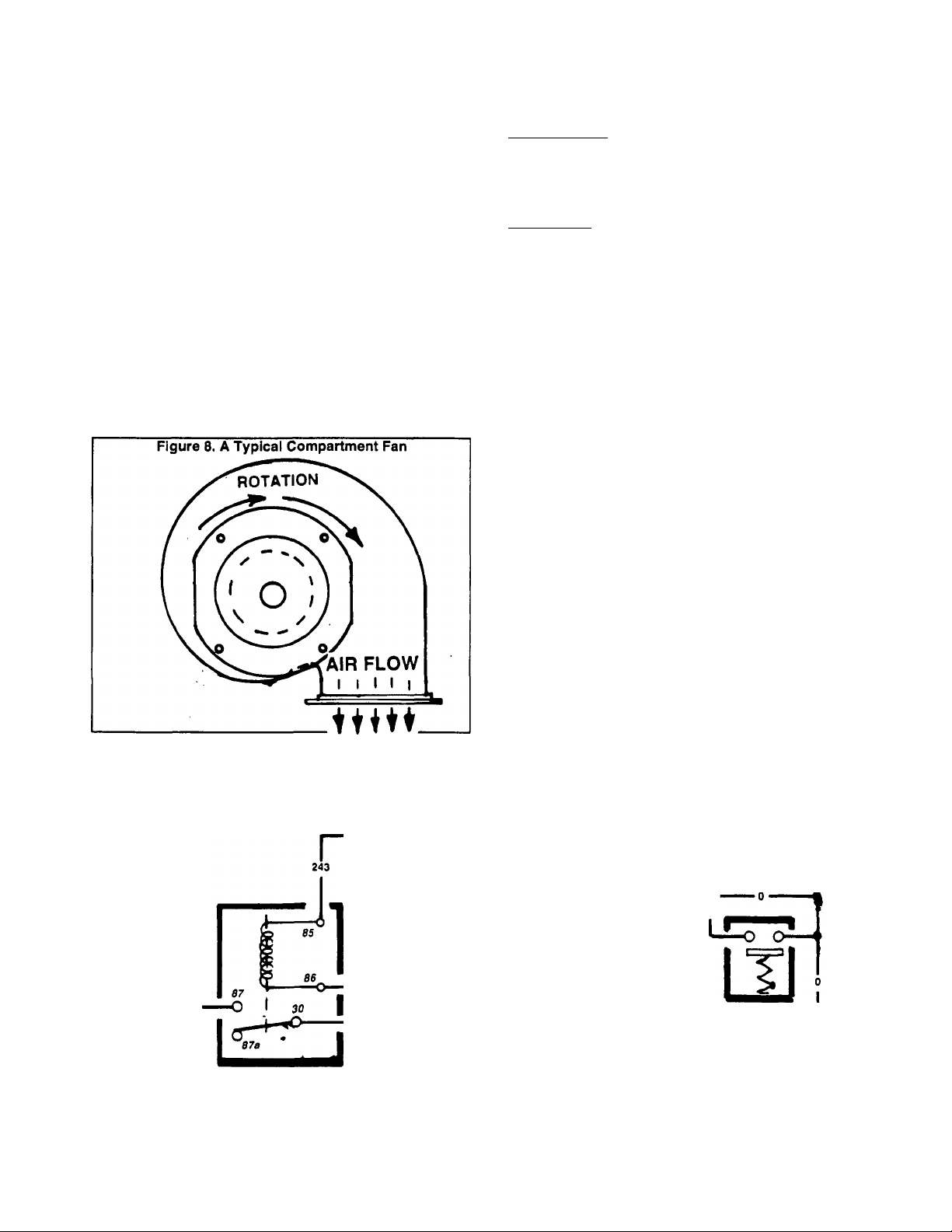
Section 4.4- OPTIONAL REMOTE RADIATOR FAN
Some NP senes engine-generators are not equipped
with a unit-mounted radiator. The radiator on such units is
mounted at a remote location in the vehicle that houses the
generator. Such installations might require the following
options:
An electrically operated RADIATOR FAN, along with a
temperature sensor switch.
A squirrel cage type COMPARTMENT FAN which draws
cooling and ventilating air through the compartment housing
the generator.
Compartment Fan
The compartment fan (Figure 8) must be properly lo
cated during installation. When running, it must draw cooling
and ventilating air through the generator compartment and
expel the air to the outdoors. The compartment fan is needed,
since an engine-driven fan Is not provided.
The compartment fan motor is connected to generator
AC output leads 11 and 22. When the generator is running
and AC voltage is available, the fan will operate.
A Remote Radiator Assembly
COMPONENTS:
Major components of a typical remote radiator and fan
include (a) the radiator, (b) the fan, (c) a thermostatic switch,
(d) mounting hardware, and (e) wiring harnesses. See Figure
10 on next page.
OPERATION:
See Figure 9, below. Battery voltage for fan operation is
always available to Tewrminal 30 of the Fan Relay (SR), via
a 14 amp fuse and Wire 13A. However, the fan relay normallyopen contacts are open and the fan Is NOT running. On
cranking and startup of the generator, an engine control
circuit board delivers 12 volts DC to the Thermostatic Switch
(TS) via Wire 14, Relay Coil, and Wire 243. If coolant temper
ature is below approximately 180' F., the thermostatic switch
contacts will be open. As soon as coolant temperature In
creases above 180' F., the switch contacts close and Wire
243 is grounded. Fan Relay (SR) then energizes, its normally-
open contacts close, and DC voltage is delivered to the FAN
via Wire 244. The fan is now powered and will run.
^ 244
.244 .
Figure 9. Remote Radiator Fan Operating Diagram
i)tt
NOTE: ThermottaUc switch contacts close above 2^3
FAN
RELAY
■ 13A .
^80" F.; fan relay contacts are energised closed
when switch contacts close.
12VDC WITH
- 14——
14 AMP
FUSE
ENGINE RUNNING
"only
,12 VDC FAN
POWER SUPPLY
L
THERMOSTATIC
7777777
Page 4.4-1
Page 57

ITEM QTY
1 1
2
3
4 1 Remote Fan Harness
5 4 Fan to Radiator Brackets 14
6 1
7 4 M5-0.80 X 10mm Capscrew 16
8
9 4
1 Radiator Fan
4 Fan Mounting Bracket 12 4 M6 Hex Nut
4 MS Lockwasher 17
DESCRIPTION
Radiator Assembly
Radiator Cap
M5-1.00 X 12mm Capscrew
ITEM QTY
wM^.
■
Page 4.4-2
DESCRIPTION
10 4
11 4
13 1
15 4 In. Flex-Gard
18
6
6.5 in.
—
1
M6 Flatwasher
M6 Lockwasher
M6 Star Washer
Tie Wrap
Flex-Gard
Pipe Sealant
Thermostatic Switch
Page 58

Section 4.5- OPTIONAL HEAT RECOVERY SYSTEM
Some IM (Industrial Mobile) engine-generators are
General
equipped with a heat recovery system. If desired, the cus
tomer can use this system to provide heated air while working
in cold areas (such as a manhole).
Operation
Figure 1, below, is a schematic diagram of a heat recov
ery system. Factory Installed components include (a) a heat
exchanger, fb) a control valve, (c) a thermostat, (d) the engine
radiator, and (e) interconnecting hoses and fittings. Operation
may be briefly described as follows;
1. Coolant from the engine flows through the heat exchanger
where it is heated by the engine exhaust, which also passes
through the heat exchanger.
2. From the heat exchanger, coolant flows to a control valve
(CV). The control valve can be positioned manually, as fol
lows:
a. It can be actuated manually to direct coolant through a
customer-supplied remote heater and then to a thermostat
housing (TH).
b. It can be actuated manually to direct coolant to the
thermostat housing (TH) and not to the customer’s remote
heater.
3. The thermostat (TH) either delivers the coolant back to the
engine or to the unit radiator, as follows:
a. If coolant temperature Is less than 192’ F. (89’ C.),
additional cooling is not needed, and the coolant Is deliv
ered back to the engine.
b. If coolant temperature is greater than 192’ F. (89’ C.),
additional cooling is needed, and the coolant is delivered
to the unit radiator and then back to the engine.
This heater is usually supplied by the user, in conjunction
with a fan or blower to extract the heat from the remote heater
and deliver it to the desired work area(s). The user must
ensure that the entire system has been properly filled with the
recommended coolant mixture prior to use.
Exploded View of Heat Recovery System
Customer Remote Heater
system. Parts included in the drawing are iisted below.
ITEM DESCRIPTION
1 Exhaust Manifold
2 End Plate
3 Thermostat Hsng.
4 Thermostat
5 Gasket
6 Water Pump
7 Lockwasher
8 Hex Nut
9 Stud
10 Fitting
12 Pipe Plug
13 Gasket
14 Gasket
15 Gasket
16 Fitting
17 90* Fitting
18 Brass Fitting
19 Gasket
Figure 12 (next page) shows a typical heat recovery
ITEM DESCRIPTION
20 Filler Neck
21 Radiator Cap
22 Exhaust Flange
23 Hose Clamp
24 Upper Hose
25 Lower Hose
26 Hose
27 Hose
28 Hose
29 Stud
30 Stud
31 Stud
32 Pipe Plug
34 Hose
35 Fitting
36 Hose Clamp
37 Lifting Lug
38 Lockwasher
Figure 11. Schematic Diagram- Engine Cooling and Heat Exchanger System
Page 4.5-1
Page 59

Figure 12. Exploded View of Heat Recovery System
Page 4.5-2
Page 60

Part 5
GASOLINE
FUEL
SYSTEM
NP and IM Series
RECREATIONAL
VEHICLE &
INDUSTRIAL
SECTION
5.1
5.2
5.3
TABLE OF CONTENTS
TITLE
General information
Fuel Pump
Carburetor
MOBILE
AC GENERATORS
1.2 Liter, Liquid-Cooled
Gas/Gasollne Engine Models
Page 61
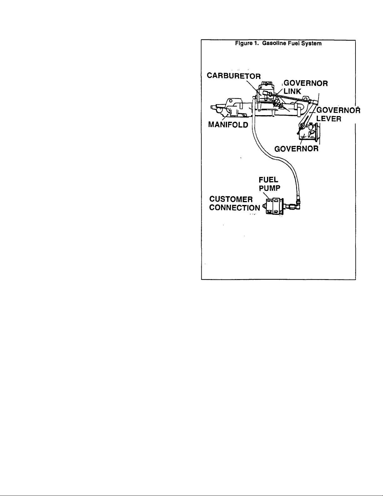
Section 5.1- GENERAL INFORMATION
Any high quality LEADED or UNLEADED regular grade
iasoline having a minimum posted octane number of 86
?
research octane number 90) is satisfactory for use with RV
and IM generators.
Use of any gasoline containing alcohol (either methanol
or ethanol) Is NOT RECOMMENDED. Gasolines containing
alcohol tend to absorb moisture from the air. Such absorption
causes the water and alcohol to separate from the gasoline
in the fuel tank. The adverse affects of alcohol increase in
severity with methyl alcohol (methanol). In addition, the ad
verse affects worsen with increasing alcohol content. Use of
gasoline containing alcohol may result in one or more of the
following:
D Corrosion of metal parts.
Fuel Recommendations
CD Deterioration of elastomer and plastic parts,
n Fuel permeation through flexible fuel lines.
D Wear and damage of internal engine parts.
D Starting and operating difficulties.
If the use of gasoline containing alcohol cannot be
avoided, do not store the gasoiine in fuel tank for long periods
of time. Long periods of fuel storage create unique problems.
Fuel System Components
Major gasoline fuel system components include (at a fuel
pump, (b) the carburetor, and (c) interconnecting fuel lines.
See Figure 1.
When the engine is cranked and started, the 12 volts DC
electric fuel pump is turned ON. At the same time, a solenoid
actuated fuel shutoff valve on the carburetor is opened to
allow fuel flow to the caiburetor.
The carburetor mounts an automatic electric choke
which closes the carburetor choke valve while the engine is
being cranked.
Carburetor throttle valve setting is established by the
action of a constant speed governor. Most generator models
utilize a mechanical, flyweight type governor. Some models,
however, may be equipped with an electronic governor.
#
Page 5.1-1
Page 62

Section 5.2- FUEL PUMP
The fuel pump Is energized ON during cranking and
General
running when an engine controller circuit board delivers 12
volts DC power to a Wire No. 14 circuit. Circuit board action
also energizes (a) a fuel solenoid, (b) a choke heater, and (c)
the engine ignition system.
Testing the Fuel Pump
Use an ohmmeter or a volt-ohm-mllliammeter (VOM) to
test the pump windings for continuity.
To perform an operational test of the pump, disconnect
fuel line from the punp outlet side and connect pump inlet
side to a fuel supply. Connect a +12 volts DC power supply
(such as a battery) to the pump WHITE wire and a -12volts
DC power to the pump’s BLACK wire. The pump should
operate and pump fuel. Replace pump. If defective.
Figure 2. Eiectric Fuel Pump
Page 5.2-1
Page 63

Section 5.3- CARBURETOR
Remove carburetor air intake components as necessary
to gain access to the carburetor. Disconnect the carburetorgovernor link. Disconnect fuel line. Remove carburetor, car
buretor adapter and gaskets.
Disassembly
Removal
See Figure 5 on next page. Disassemble the carburetor
as follows:
1. Remove two screws and lockwashers, then remove FUEL
INLET PLATE and GASKET.
2. Remove two screws and washerts, then remove CHOKE
SOLENOID ASSY.
3. Remove four screws and washers, then remove FLOAT
BOWL COVER along with FLOAT BOWL GASKET, FLOAT,
FLOAT SHAFT, SPfflNG, FUEL VALVE AND SEAT ASSY.
4. Remove FLOAT SHAFT, SPRING, FUEL VALVE and
FLOAT.
5. Remove FLOAT BOWL GASKET.
6. Remove SEAT ASSY.
7. Remove two CHOKE PLATE SCREWS, then remove
CHOKE PLATE.
8. If necessary for replacement, remove FUEL SOLENOID
and seal.
9. Remove IDLE ADJUSTING NEEDLE & SPRING.
10. Clean all parts in clean gasoline.
Reassembly
Reassemble all parts in the reverse order of disassem
bly. During the reassembly process, install new parts from
carburetor repair kit. Pay close attention to the following:
D Open throttle plate slightly for idle speed.
D Set the Idle adjusting needle 3/4 turn open.
With float bowl cover inverted and float bowl gasket
installed, set float level 0.125 inch (3.175mm) from the float
bowl gasket (see Figure 1).
Tighten air intake mounting screws. Make sure the throt
tle shaft rotates freely. Tighten the FUEL SOLENOID to 70
inch-pounds.
Insert short leg of CHOKE SHAFT SPRING into small
hole in CHOKE SHAFT (Figure 2). Wind SPRING 1-1/2 turns
counterclockwise, anchor on retaining screw boss.
Install casket, adapter, gasket and carburetor. Retain
Installation
with socket head machine screws.
Automatic Choke Adjustment
Loosen CHOKE SOLENOID adjusting screws and adjust
choke position so that, with the solenoid pulled in (energized),
the choke piate is closed. With choke plate closed, tighten the
adjusting screws. Then, with solenoid extended, bend tip of
the bi-metal until choke plate is about 1/8 inch from vertical
and towards the closed position.
Page 64

Page 5.3-2
Page 65

Part 6
SECTION
6.1
TABLE OF CONTENTS
TITLE
Introduction to Gaseous Fuel
Systems
GASEOUS
FUEL
SYSTEM
NP and IM Series
RECREATIONAL
VEHICLE &
INDUSTRIAL
MOBILE
AC GENERATORS
1.2 Liter, Liquid-Cooled
Gas/Gasoline Engine Models
6.2
6.3
Major Components- Liquid
Withdrawal System
Major Components- Vapor
Withdrawal System
Page 66
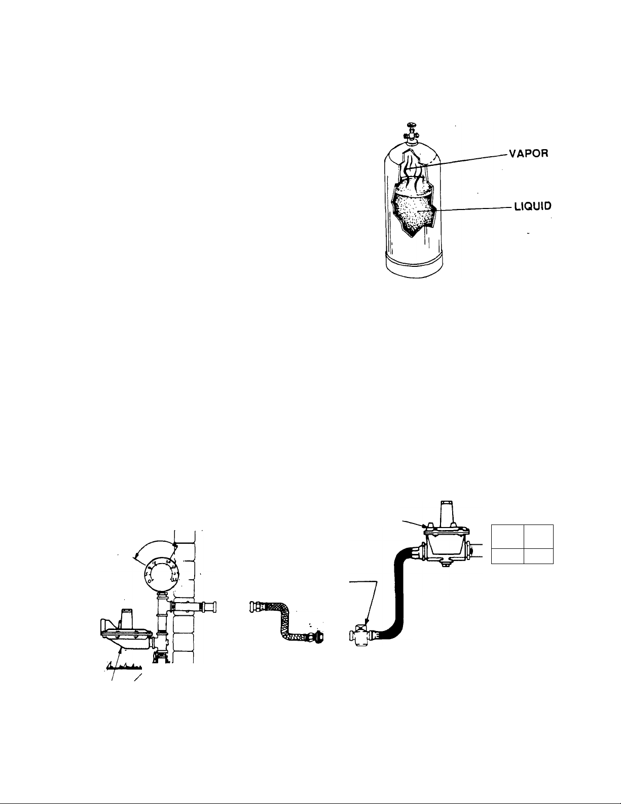
Section 6.1- INTRO. TO GASEOUS FUEL SYSTEMS
Some NP/IM series engine-generators may be equif^ed
General
with optional LP (liquefied petroleum) gas fuel systems. This
fuel is supplied as a liquid in pressure tanks.
LP gas is usually made up of (a) propane, (b) butane, or
(c) a mixture of the two gases. The liquefied fuel must be
converted to its vapor state before it enters the engine carbu
retor. Propane will vaporize at temperatures as low as 20' F.
(-6.7‘ C.). Butane exists in its liquid state when temperatures
drop below 32' F. (O’ C.). In colder weather, fuel suppliers will
usually increase the amount of propane in the fuel mixture for
better vaporization. Under extremely cold conditions, butane
gas may not provide sufficient vapor pressure to operate the
engine.
Q One gallon of butane liquid equals about 31.26 cubic feet
of butane gas.
EH One gallon of propane equals about 36.39 cubic feet of
propane gas.
Vapor Withdrawal System
The LP gas fuel system may be either (a) a vapor
withdrawal system or (b) a liquid withdrawal system.
The vapor withdrawal system utilizes the vapors that
form above the liquid fuel in the supply tank. One typical
vapor withdrawal supply tank is shown in Figure 1.
The vapor withdrawal system, because it uses qaseous
fuel vapors. Is much like a natural gas system. See Figure 2.
The fuel vapors are delivered to a customer-supplied primary
regulator which reduces the gas vapor pressure. The gas
then goes to a fuel lockoff solenoid. Optimum gaseous pres
sure at the inlet to the fuel lockoff solenoid is about 11 inches
(water column) and not to exceed 14 inches (water column).
The function of the primary regulator is to provide this opti
mum fuel pressure to the solenoid. From the fuel lockoff
solenoid, the gaseous fuel is delivered to the inlet of a
pressure reducer valve. The pressure reducervalve receives
the gas at the stated optimum pressure, reduces the gas
pressure to a negative (vacuum) pressure of about -1 inch
(water column). The gas is then delivered to the carburetor
which meters the gas to the engine based on engine demand.
Figure 1. Typical Vapor Withdrawal Supply Tank
Liquid Withdrawai System
A typical liquid withdrawal fuel supply tank is shown in
Figure 3 (next page). A pickup tube extends down into the
tank. Vapor pressure on top of the fuel in the tank forces the
fuel to flow through the pickup tube and to the engine-gener
ator fuel system.
A typical liquid withdrawal type fuel system is shown in
Figure 4 on the next page. From the fuel supply tank, liquid
fuel flows to a fuel lockoff solenoid on the generator. The
liquid fuel Is then delivered to a vaporizer-regulator. Heated
engine coolant also flows through the vaporizer-regulator, to
heat the fuel and change it to its vapor state. The vaporized
fuel is then delivered to the engine carburetor at greatly
reduced pressure.
11 In. H20
OPTIMUM
? FROM SUPPLY TANK
PRIMARY REGULATOR
Figure 2. A Typical Vapor Withdrawal System
SECONDARY REGULATOR
FUEL SHUTOFF VALVE
r CARBURETOR-
'r
br
I
Page 6.1-1
Page 67

As the throttle is opened wider, air flow increases through
the carburetor venturi and the vacuum at the venturi throat
Increases proportionally. Diaphragm movement increases,
the regulator metering valve opens further, and gas flow to
the carburetor increases.
The following facts apply to venturi type gas carburetion
systems:
n The regulator must be properly adjusted so that it will
stop the flow of gas when the engine is not running.
D The slightest vacuum should lift the regulator metering
valve off its seat and allow gas flow to the engine.
D If diaphragm spring force is excessive, too much vacuum
will be needed to open the regulator metering valve. This
will result in a flat spot or sluggish progression off idle.
Lean mixtures and power loss at full loao may also result.
D If diaphragm spring force is too weak, fuel leakage after
shutdown may result. Hard starting and the danger of fire
exist.
See Figure 5. During the engine Intake stroke, air is
Gas Carburation
drawn into the engine. This air flows through a venturi in the
carburetor and creates a vacuum at the venturi throat. The
amount of vacuum created is proportional to the amount of
air flow. That is, the greater the air flow through the venturi,
the greater the amount of vacuum.
The vacuum created at the carburetor venturi throat acts
on a diaphragm in the vaporizer-regulator (liquid withdrawal
system) or pressure reducer valve (vapor withdrawal), to pull
the diaphragm toward the source of vacuum. Diaphragm
movement opens a metering valve and allows gas to flow to
the carburetor.
DANGER: GASEOUS FUEL REGULATORS MUST
BE PROPERLY ADJUSTED AND TESTED AT THE
TIME OF INSTALLATION, TO PREVENT GAS
LEAKAGE AND POSSIBLE FIRE OR EXPLOSION.
INSTALLATION, ADJUSTMENT AND TESTING
SHOULD BE ACCOMPLISHED ONLY BY QUALI
FIED GAS SERVICE TECHNICIANS. THE GAS
FUEL SYSTEM MUST COMPLY WITH ANSI
119.2/NFPA 501C, CHAPTER 2, “FUEL SYSTEMS
AND EQUIPMENT". FOLLOWING INSTALLATION
THE SYSTEM MUST BE PROPERLY PURGED AND
LEAK TESTED. NO LEAKAGE IS PERMISSIBLE.
LP Gas Conversion Kit
An LP gas conversion kit is available for installation on
NP and IM generators with 1.2 liter gas engine. Installation of
thé proper conversion kit will allow LP gas to be used as a
fuel. The Model 9251 kit is a vapor withdrawal type; Model
9052 is a liquid withdrawal type. The kits do not include fuel
supply tanks, nor do they include fittings, lines, etc., required
to store the fuel and deliver the fuel to the fuel lockoff solenoid.
Instructions are included with the kit. To order instructions
only, specify manual Part No. 78360.
A primary regulator Is required for vapor withdrawal
systems. That regulator is not included in the kit.
Page 6.1-2
Page 68
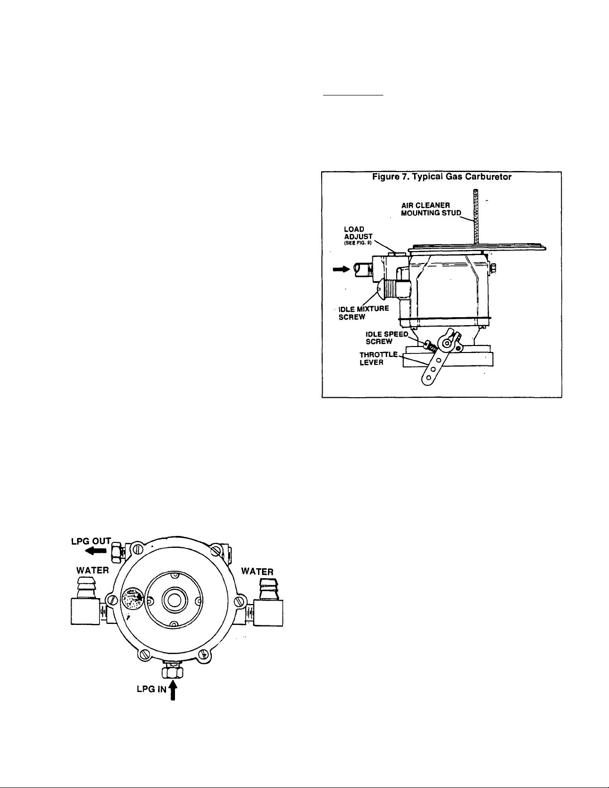
Section 6.2- LIQUID WITHDRAWAL SYSTEMS
Figure 8 (next page) is an Exploded View of a typical
Introduction
LIQUID WITHDRAWAL type gaseous fuel system. Major
components of the system include the following:
D Fuel Solenoid Assembly,
n Vaporizer-Regulator Assembly,
n Carburetor Assembly.
D Air Cleaner Assembly,
n Interconnecting lines and fittings.
Fuel Solenoid Assembly
See Item 12, Figure 8. The electrically actuated fuel
solenoid is energized open, de-energized closed. Mainte
nance on this part Is generally limited to replacement of the
entire solenoid assembly.
NOTE: If the fuel solenoid assembly must be replaced,
use only an assembly that Is useable with a liquid with
drawal system. Fuel solenoids are not Interchangeable
between liquid and vapor withdrawal systems. Fuel
solenoids used on liquid withdrawal systems must be
rated at a much higher pressure than vapor withdrawal
solenoids.
Vaporizer-Regulator Assembly
The vaporizer-regulator included with the Model 9052 LP
gas conversion kit is an IMPCO Model JB. The vaporizer-reg
ulator must perform the following functions:
Carburetor Assembly
DESCRIPTION:
The carburetor assembly included with the Model 9052
gas conversion kit is an IMPCO Model CA50-506. See
Figure 7.
Vaporizer-regulator and carburetor operation are de
scribed under "GAS (^ARBURETION" on Page 6.1-2.
The carburetor is equipped with (a) an idle mixture ad
justment, and (b) a load adjustment.
n It must positively stop the flow of gas when the engine is
not running.
D At the slightest vacuum, the regulator metering valve
must move off its seat and allow gas flow to the engine,
n Heated engine coolant, passing through the vaporizer-
regulator, must vaporize the liquid fuel before it reaches
the carburetor.
See Figure 6. Engine coolant lines connect to the vapor
izer-regulator, as well as inlet and outlet lines for LP gas.
Figure 6. Vaporizer-Regulator
ADJUSTMENTS:
Idle Mixture: This adjustment affects fuel-air mixture
only when the engine is running at idle speed. It has no affect
on operation at the engine’s normal rated speed of approxi
mately 1800 rpm and, for that reason, adjustment is not
required. However, if you wish to adjust idle mixture, proceed
as follows:
1. Connect an AC frequency meter to the generator’s AC
power output leads.
2. Disconnect all electrical loads from the generator.
3. Start the engine, let it stabilize and warm up at no-load.
4. Reduce engine speed until frequency meter reads approx
imately 30-33 Hertz.
5. Slowly turn the idle mixture screw clockwise until engine
starts to run rough. Then, turn the screw counterclockwise
until engine again starts to run rough. Finally, turn the screw
clockwise until smooth operation is obtained.
Load Adjustment: This is an adjustment of fuel-air
mixture with the rated load of the unit applied. Complete the
adjustment as follows:
1. Connect an AC frequency meter to the generator’s AC
power output leads.
2. Disconnect all electrical loads. This can be done by setting
the main circuit breaker to "Off“ or "Open".
3. See Figure 9. Turn the load adjustment as far as it will go
toward the "R" (maximum rich).
4. Start the engine, let it stabilize and warm up at no-load.
Page 6.2-1
Page 69
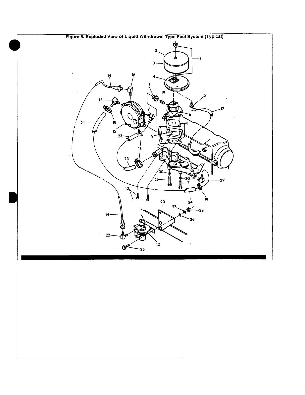
Parts List for Liquid Withdrawal Fuel System
ITEM QTY
1
2 1
3
4
5 1
6
7
8
9 1
10 2
11 1
12
13
14 1
15
NOTE 1: Carburetor adapter shown is for units with mechanical governor.
Page 6.2-2
1
1
1
1
1
2
1
2
1
3/8" NPT X 1/2" Barbed 90’ Fitting 20 1
Carburetor Adapter (See Note 1) 24 1
5/16"-18 X 1" Socket Head Capscrew
3/8" NPT X 5/8" 90* Barbed Fitting 28 2
DESCRIPTION ITEM QTY
Air Cleaner Stud 16
Air Cleaner Cover 17
Air Cleaner Element
Air Cleaner Adapter 19 1
Carburetor Assembly
M8-1.25 X 65mm Capscrew 22 1
Carburetor Gasket 23 1
1" to 3/8" Reducer 26 2
Fuel Solenoid Assembly
LP Gas Fuel Line 29
LP Gas Vaporizer-Regulator
18
21
25 2
27 2
30 2
DESCRIPTION
1
1
4
1
1
1/4" NPT Brass Elbow
Ventilation Hose
" NPT X 1-1/2" long Pipe Nipple
3/8
Solenoid Mounting Bracket
M8-1.25 X 50mm Capscrew
1/4" NPT 90’ Fitting (Brass)
M6-1.00 X 25mm Capscrew
Hose Clamp
5/8" IDxll" long Hose
5/8" ID X 20" long Hose
M6 Flatwasher
M6 Lockwasher
M6 Nut
1/2" NPT X 5/8" 90* Elbow
M8 Lockwasher
Page 70

Carburetor Assembly (Continued)
ADJUSTMENTS (CONTINUED):
5. Apply an electrical load to the unit equal to the generator’s
rated maximum continuous wattage/amperage capacity.
6. Slowiy turn the load adjustment toward the ’L" (leaner) until
the engine starts to run rough and frequency meter reading
starts to decrease.
7. Slowly turn the load adjustment back toward "R" (richer)
until engine starts to run rough and frequency meter reading
again starts to decrease.
8. Turn the load adjustment toward the "L" (leaner) until
smooth operation and highest frequency is obtained.
9. Turn off all electrical loads and check frequency reading.
The no-load frequency should be 60.5-63.5 Hertz for 60 Hertz
units; or 49-52 Hertz for 50 Hertz units.
NOTE: If the no-load frequency reading Is Incorrect,
adjustment of the engine governor may be required. See
Part 7, "ENGINE SPEED CONTROL SYSTEM".
Page 6.2-3
Page 71
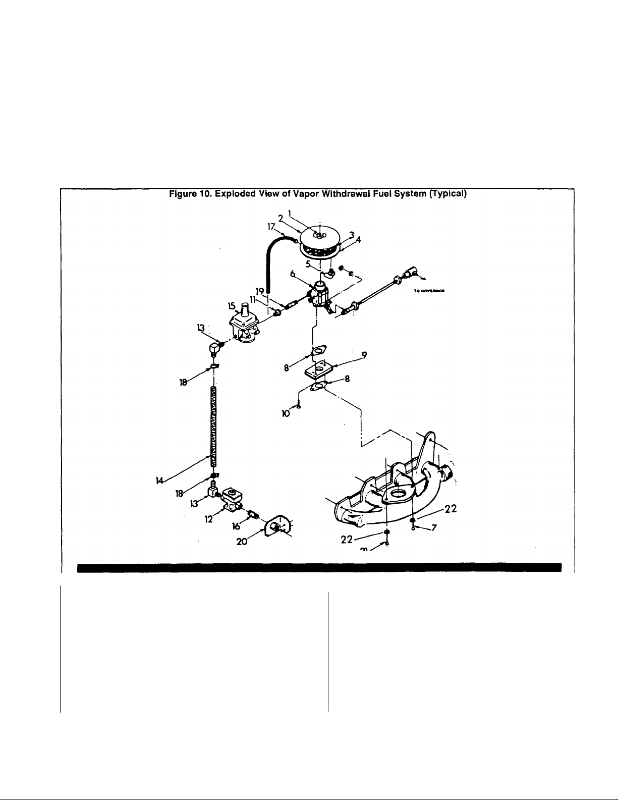
Section 6.3- VAPOR WITHDRAWAL SYSTEM
Figure 10 (below) is an Exploded View of a typical
Introduction
VAPOR WITHDRAWAL type gaseous fuel system. Major
components include the following;
D Fuel Solenoid Assembly.
CH Pressure Reducer Valve.
D Carburetor Assembly.
D Air Cleaner.
n Interconnecting lines and fittings.
The electrically actuated fuel solenoid is energized open,
Fuel Solenoid Assembly
de-energized closed. Maintenance is generally limited to
replacement of the solenoid assembly. When replacing the
solenoid be sure to use the correct one for the system.
Solenoids are not interchangeable between liquid and vapor
withdrawal systems.
The solenoid is energized open by 12 volts DC during
cranking and running. On shutdown, the solenoid must pos
itively close to stop the flow of gas through the system.
Parts List for Vapor Withdrawal Fuel System
ITEM QTY
1
2 1
3
4
5
6
7
8
9
10 2
11 1
NOTE: Carburetor adapter shown Is for units with mechanical engine governor.
1
1
1
1
1
1
2
1
3/8“ NPT X 1/2“ Barbed Fitting (90‘)
5/16’’-18 X 1 ” Socket Head Capscrew
DESCRIPTION
Air Cleaner Stud
Air Cleaner Cover
Air Cleaner Element
Air Cleaner Adapter
Carburetor Assembly
M8-1.25 X 65mm Capscrew
Carburetor Gasket
Carburetor Adapter (NOTE 1)
3/4" to 3/8" Reducer
ITEM QTY
12
13
14
15
16
17
18
19
20
21
22 2
DESCRIPTION
1
2
1
1
1
1
2
1
1
1
Fuel Solenoid Assembly
3/4“ NPT X 5/8” 90* Barbed Fitting
5/8" ID X 18-3/4“ long Hose
Pressure Reducer Valve
3/4" NPT Nipple
Ventilation Hose
Hose Clamp
3/8“ NPT X 1“ long Pipe Nipple
Solenoid Bracket
M8-1.25 X 50mm Capscrew
M8 Lockwasher
Page 6.3-1
Page 72

The pressure reducer valve used in the Model 9251 LP
Pressure Reducer Valve
gas conversion kit is an IMPCO Model IMP-52. LP gas, in
vapor form, is delivered to the valve inlet at approximately 11
inches (water column). Valve inlet pressure should not ex
ceed 14 inches (water column). The pressure reducer valve
provides a regulated pressure decrease down to approxi
mately minus 1 inch (water column) and delivers this reduced
(vacuum) pressure to the carburetor.
The pressure reducer valve is designed for both natural
nd LP gas fuel systems. For LP gas vapor withdrawal
a,
applications, it must be modified as follows (Figure 12):
ai
•
1. Remove END CAP.
2. Remove ITEMS B and A.
3. Install and tighten END CAP.
4. Install the valve In the position
shown (spring neck down).
The Models 9052 liquid withdrawal system and the Model
Carburetor Assembly
9251 vapor withdrawal system both utilize an IMPCO CA50506 carburetor. Refer to ’CARBURETOR ASSEMBLY’ on
Pages 6.2-1, 6.2-2 and 6.2-3.
Page 6.3-2
Page 73

Part 7
ENGINE
SPEED
CONTROL
SYSTEM
NP and IM Series
RECREATIONAL
VEHICLE &
INDUSTRIAL
TABLE OF CONTENTS
SECTION
7.1
7.2
TITLE
Mechanical Governor
Electronic Governor
MOBILE
AC GENERATORS
1.2 Liter, Liquid-Cooled
Gas/Gasoline Engine Models
Page 74
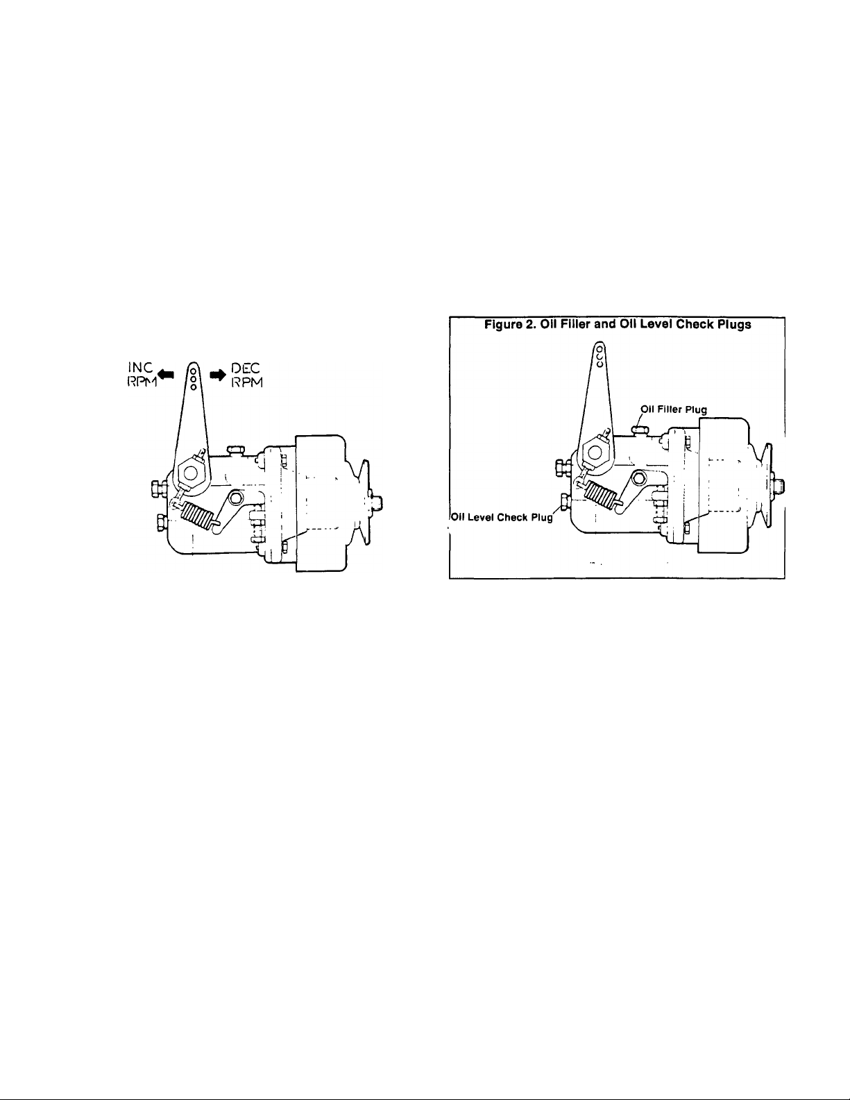
Section 7.1- MECHANICAL GOVERNOR
The mechanical engine governor utilizes the principle of
General Description
spring tension versus centrifugal force to maintain a steady
state engine speed, regardless of the applied load. When
centrifugal flyweight force exceeds governor spring tension,
the flyweights act on a yoke to rotate a rocker shaft. Rocker
shaft rotation decreases carburetor throttle setting and en
gine speed decreases. As engine speed decreases, governor
spring tension becomes greater than flyweight centrifugal
force. The spring then increases carburetor throttle setting
and engine speed increases. The governed speed is that
rpm at which flyweight force and spring force are equal.
The governor flyweights are driven by an engine v-belt.
The pulley which drives the flyweights also dnves a DC
alternator assembly, used to maintain battery state of charge
during engine operation.
Figure 1. Mechanical Engine Governor
Reassemble the DC alternator in the reverse order of re
moval. Install socket head screws that retain the stator and
tighten them to 5 foot-pounds (7 N-m). Tighten the hex jam
nut to 35 foot-pounds (47 N-m).
Governor Lubrication
See Figure 2. To fill the governor with oil, proceed as
follows:
1. Remove OIL FILLER PLUG and OIL LEVEL CHECK
PLUG,
2. Add engine oil through FILLER PLUG until oil just starts to
overflow the OIL LEVEL CHECK PLUG opening. Pour slowly.
3. When oil level is correct, install and tighten OIL FILLER
and OIL LEVEL CHECK PLUGS.
Maintenance and repair of the governor is limited to the
Governor Maintenance
following;
n Removal and replacement of the DC alternator assem-
bly.
□ Removal and replacement of governor lever, links and
springs.
D Removal, replacement and adjustment of governor to
carburetor linkage.
CH Adjustment of governed speed.
dC Alternator Removal
Refer to Figure 4 on next page. Remove the DC alterna
tor assembly as follows:
1. Remove hex jam nut (Item 43), wave washer (Item 48), and
pulley half (Item 44).
2. Remove the DC alternator Rotor (Item 44).
3. Remove socket head screws (Item 35) and lockwashers
(Item 22).
4. Remove the Stator (Item 47).
1. Connect an AC frequency meter across the generator’s AC
Engine Governor Adjustment
output leads.
2. Turn OFF all electrical loads. Initial adjustments will be
accomplished at no-load.
3. Start the engine, let it stabilize and warm up.
4. Check the no-load AC frequency. Readings should be as
follows:
Units Rated at 60 Hertz = 60.5-63.5 Hertz
Units Rated 50 Hertz = 49-51 Hertz
5. No-Load Governed Speed Adjustment: If adjustment of
no-load governed speed is required, proceed as follows (see
Figure 3):
a. Loosen the NO-LOAD BUMPER SCREW lock nut, then
loosen the NO-LOAD BUMPER SCREW so the governor
is not pre-loaded.
b. Adjust the NO-LOAD SPEED ADJUST SCREW to ob
tain a frequency reading as close as possible to 61.5 Hertz
for units rated 60 Hertz; or to 50.0 Hertz for units rated 50
Hertz.
c. Adjust the NO-LOAD BUMPER SCREW to obtain a
frequency of 62 Hertz (60 Hertz units); or 51 Hertz (50 hertz
units).
6. Adjustment Under Load: Apply an electrical load to the
generator equal to the rated wattage/amperage capacity of
the generator. Then, proceed as follows:
Page 7.1-1
Page 75

4
Figure 4. Exploded View of Governor-DC Alternator Assembly
ITEM
1
2
3
4
5
6
7
8
9
10
11
12
13
14
15
16
17
18
19
20
21
22
23
25
26
27
28
DESCRIPTION
Governor Housing
0-Rlng Seal
Governor Flange
Drive Shaft Assembly
Ball Bearing
Oil Seal
Ball Bearing
Truss Head Screw
Flyweight
Flyweight
Dowel Pin
External Retaining Ring
Thrust Sleeve
Needle Bearing
Thrust Washer
Thrust Washer
Roll Pin
External Retaining Ring
Inner Ring Bushing
Bearing Draw Cup
M4-0.70 Hex Screw
M4 Lockwasher
Yoke
Rocker Shaft
Oil Seal
Ball Bearing
Externai Retaining Ring
ITEM
29
30
31
32
33
34
35
36
37
38
39
40
41
42
43
44
45
46
47
48
49
50
51
52
53
54
55
DESCRIPTION
M6-1.00 Hex Screw
M6 Lockwasher
Tension Bracket
Tension Bracket Bushing
M6-i.00 Hex Screw
Sealing Washer
M4-0.70 SWocket Head Capscrew
M6-1.00 Hex Screw
M6-1.00 Nut
Bumper Screw
Compression Spring
1/8“ NPT Pipe Plug
Spacer
Pulley Half
Hex Jam Nut
DC Alternator
Cable Clamp
M4-0.70 Pan Head Screw
DC Stator Assembly
Wave Washer
Tension Spring
M6-1.00 Hex Nut
M6-1.00 Screw
Governor Lever
Governor-Carburetor Link
Ball Joint
No. 10-32 Flanged Lock Nut
Page 7.1-2
Page 76
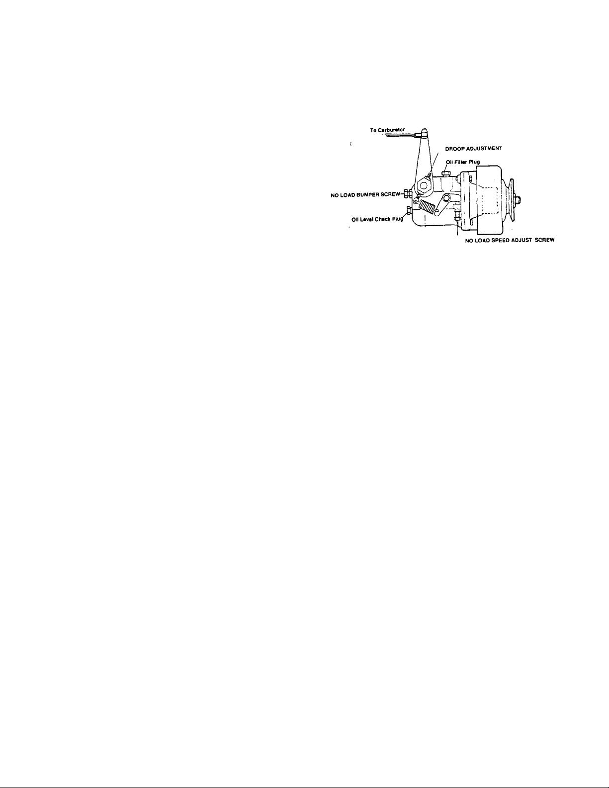
Engine Governor Adjustment (Continued)
a. Check the AC frequency reading under load.
b. If frequency drops below about 58 Hertz (60 Hertz units)
or 49 Hertz (50 Hertz units) under load, adjust the DROOP
ADJUSTMENT downward until application of the load
results in the smallest possible AC frequency droop when
maximum load is applied.
NOTE: If surging occurs when electrical load Is removed,
adjust the NO-LOAD BUMPER SCREW Inward. If
BUMPER SCREW adjustment changes the AC frequency
reading, back the NO-LOAD BUMPER SCREW out until
no-load frequency returns to 62 Hertz (60 Hertz units); or
to 51 Hertz (50 Hertz units).
NOTE: With unit running at correct AC frequency, you
may wish to check the generator’s AC output voltage. If
frequency reading Is correct, but voltage reading Is In
correct, adjustment of the AC voltage regulator may be
required.
Figure 3. Governor Adjustment Points
Page 7.1-3
Page 77

Section 7.2- ELECTRONIC GOVERNOR
Some industrial mobile (IM) series generators may be
General
equipped with an electronic engine governor system. The
system consists of the following major components:
n A 12 volts DC Governor Actuator Relay (GAR).
■ n An Electronic Governor Actuator (EGA),
n An Electronic Governmor Control circuit board (EGC).
n A Magnetic Pickup assembly (MPU).
n Interconnecting wiring.
Figure 4 is an operating diagram of the electronic gover
nor system. Operation may be briefly described as follows:
1. During engine startup and running, an Engine Control
circuit board delivers 12 volts DC to a GOVERNOR ACTUA
TOR RELAY (GAR) via Wire No. 14. The Relay energizes
and its normally-open contacts close.
2. When the Relay contacts close, 12 volts DC is delivered to
the ELECTRONIC GOVERNOR CONTROL (EGC) circuit
board, to turn the governor system on.
3. Engine speed information is delivered to the ELECTRONIC
GOVERNOR CONTROL (EGC) circuit board from a MAG
NETIC PICKUP (MPU). This “actual* speed is electronically
compared to a "reference” speed that has been preset on the
circuit board.
4. If any difference exists between “actual" and "reference"
speed, the ELECTRONIC GOVERNOR CONTROL (EGC)
board sends speed correction signals to an ELECTRONIC
GOVERNOR ACTUATOR (EGA).
5. The ELECTRONIC GOVERNOR ACTUATOR (EGA) is
mechanically linked to the carburetor throttle valve.
Figure 4. Governor System Schematic
energize and normally-open Relay contacts 4 and 7 should
actuate closed.
With the Relay coil energized, a VOM connected across
Relay Terminals 4 and 7 should read “continuity“.
With the Relay coil de-energized, a VOM connected
across Relay Terminals 4 and 7 should read "infinity".
Figure 5. Governor Actuator Relay
COIL
NORMALLY-OPEN
CONTACTS
NORMALLY-CLOSED.
CONTACTS
A. Schematic
ysj -nr
B. Pictorial
Governor Actuator Adjustment
With the engine shut down, adjust the length of the
Electronic Governor Actuator (EGA). With the carburetor
throttle valve closed, adjust so that approximately 0.40-0.78
inch (1-2mm1 of clearance exists between the EGA stop
washer and the EGA body. See Figure 6.
GOVERNOR
CIRCUIT
BOARD
1_ 5 4 3 2 1 _|
166
169
79
168 RELAY
?
I O-
LirJ
GOVERNOR
-0-n
-15
+12 VDC
rh
1-169-TO GOVERNOR ACTUATOR
-79 — FROM RPM SENSOR
Governor Actuator Relay
DESCRIPTION;
See Figure 5. The Relay is housed in the generator
control console. The Relay coil is energized when 12 volts
DC is applied at its Terminal A and the circuit is completed
through the coil to Terminal B and to ground.
TESTING:
To test the Relay, apply +12 volts DC to Relay Terminal
A and -12 volts DC to Terminal B. The Relay coil should
Electronic Governor Setup
The Electronic Governor Control (EGC) circuit board is
housed in the generator control console (see Figure 7). All
circuit board adjustments for new generators have been
completed at the factory and no additional adjustment should
be required. If the circuit board must be replaced, adjust the
governing parameters as follows:
1. See Figure 7. Set the speed pot (R5) fully counterclock-
wise.
2. Set all other potentiometers (R12, R13, R22, R26) to their
mid-point.
Page 7.2-1
Page 78
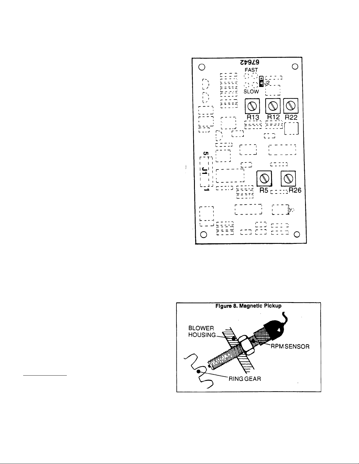
Electronic Governor Setup (Continued)
Figure 7. Electronic Governor Control Circuit Board
*
Set Jumper J2 to Its "FAST* position.
4. Adjust Speed Pot R5 clockwise to obtain the correct AC
frequency.
5. Check no-load stability. System stability can be improved
by adjusting R12 and R13 clockwise.
6. Apply 25 percent of the unifs rated load. Then, check
stability.
a. If undesireable oscillations are observed when the 25%
load is applied, adjust R22 clockwise.
b. Adjusting R22 clockwise will dampen undesireable os
cillations that occur when a load Is applied.
7. Shut the engine down. Then, restart it and observe startup
characteristics. If the overshoot that occurs during startup is
higher than desired, adjust R26 clockwise (to reduce startup
overshoot).
8. Apply rated block load to the generator. Observe the
recovery from block load application and from load dump.
a. Adjusting R12 and R13 counterclockwise will improve
recovery from block load application, but will tend to make
the system less stable.
b. Adjusting R26 counterclockwise will improve recovery
from load dump, but will allow more overshoot at startup.
Complete the preceding adjustments as required to ob
tain the best balance of all parameters. Basic guidelines for
system operation are as follows:
D The system should reach stability at all load points with
not more than four (4) oscillations.
D The system should recover to within one (1) Hertz of
steady state in less than two (2) seconds for all load
transients.
CH No-load to full-load droop should be less than 0.5 Hertz
steady state.
The Magnetic Pickup is installed into a threaded hole in
Magnetic Pickup
the generator's blower housing and prevented from turning
by a stop nut. The tip of the pickup lies directly over the
flywheel’s ring gear teeth.
To install and properly set air gap, thread the pickup in
until its tip just contacts the ring gear. Then, back off about
1/2 to 3/4 turn and hold in that position while tightening the
stop nut.
CAUTION: DO NOT rotate the engine during the
above adjustment.
Page 7.2-2
________________________________
Page 79

Part 8
ENGINE
IGNITION
SYSTEM
NP and IM Series
RECREATIONAL
VEHICLE &
INDUSTRIAL
SECTION
8.1
8.2
TABLE OF CONTENTS
TITLE
General Information
Tests, Checks and Adjustments
MOBILE
AC GENERATORS
1.2 Liter, Liquid-Cooled
Gas/Gasoline Engine Modeis
Page 80
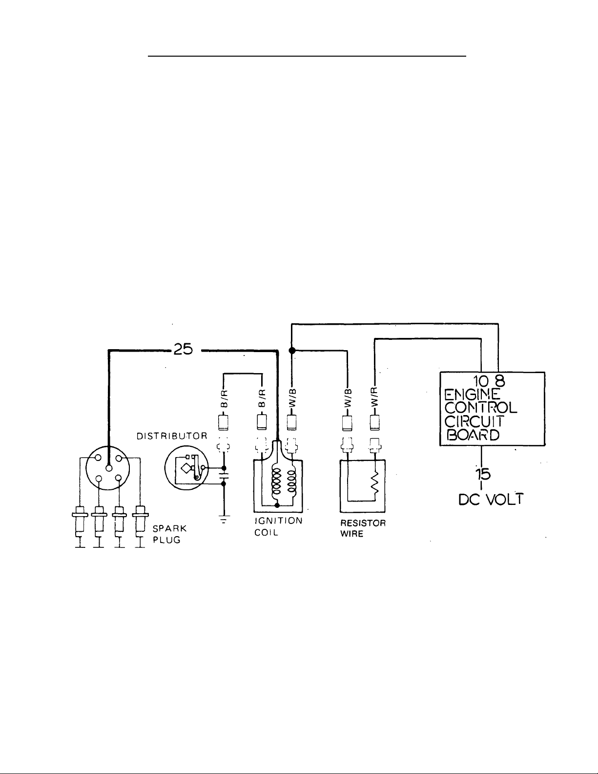
_________
Section 8.1- GENERAL INFORMATION
_________
The engine ignition system consists of (af ignition coil,
(b) a distributor, (c) spark piugs, (d) spark plug leads, and (e) Firing Order......................................1-3-4-2
an ignition resistor. Distributor Rotation
Breaker Point Gap
Distributor Cap insulation
.................
...................
Counterclockwise
0.018-0.022 inch
Ignition System Operation Resistance................................Greater than 50 meg-ohms
During engine cranking and running op^erations, an En- Head Insulation
gine Control circuit board delivers 12 volts DC to the Ignition cn
Major Components Service Data and Specifications
Coil primary winding via Wire No. 9. the coil primary winding Resistance
circuit is completed through the distributor breaker points and Distributor Cap Carbon
to ground. Each time the distributor breaker points open, the Point Length
primary circuit is opened and a magnetic lield around the (3mm) protruded length
primary coil winding collapses to induce a high voltage into ignition Coil Resistance
the ignition coil secondary winding. The high voltage from the Primary Coll 1 3-1 5 ohms
coil secondary winding jumps the gap across the spark plugs. _ ^ ^
When the engine has started, only about 7-9 v^is . Coll
required to maintain ignition. For that reason, once startup sparK Plugs bodcco
has occured, the Engine Control board terminates current NGK...................................BPR6ES
flow to Wire No. 9 and delivers current flow to the ignition coil CHAMPION
primary winding through a resistor wire (RW). AC .....................................R42XLS
Figure 1. Ignition System Diagram
.............................
............................
....................
................
.......................
Spark Plug Gap
Condenser Capacity .. .0.2-0.24 micro-farads
...............
Greater than 50 meg-ohms
More than 0.012 inch
,
8.7-11.7 k-ohms
RN9YC
0.031-0.035 Inch
Page 8.1-1
Page 81

Page 8.1-2
Page 82

Section 8.2- TESTS, CHECKS AND ADJUSTMENTS
See Figure 3. Connect the test leads of an ohmmeter
Ignition Coil
across the positive and negative terminals of the primary
v/inding. Measure the resistance.
PRIMARY WINDING RESISTANCE
AT 68* F. (20‘ C.)
1.3-1.5 ohms
Connect the ohmmeter test leads across the secondary
winding terminal and the primary winding negative terminal.
Measure the resistance.
SECONDARY WINDING RESISTANCE
AT 68* F. (20* C.)
8700-11,700 ohms
Figure 4. Checking Secondary Winding Resistance
Distributor Cap and Rotor Head
Inspect the cap and rotor head for dust, carbon deposits,
cracks. Replace, if necessary.
Contact Set
Inspect surfaces of the contact points. Irregularities may
be rernoved with No. 500 or 600 sandpaper or with oilstone.
Loosen the breaker point set screw and adjust gap with a
feeler gauge.
BREAKER POINT GAP
0.018-0.022 Inch (0.45-0.55mm)
Check Governor Advance
Turn the rotor shaft counterclockwise, then release it and
check that it returns to the clockwise position. Also check that
the rotor shaft is not excessively loose.
Use a capacity tester to check the condenser. If a capac
Checking the Condenser
ity tester is not available, avolt-ohm-milliammeter(VOM) may
be used to test the condenser, as follows:
1. S^t the VOM to a high resistance scale, such as *Rx1 K" or
”Rx10,000". Zero the meter.
2. Connect VOM test leads across the condenser. If the VOM
needle swings violently, then moves back to “Infinity" grad
ually, condenser is good. A reading of “zero” or a steady
reading indicates the condenser has failed.
2. Use a spark plug wrench to remove spark plugs.
3. Clean the spark plugs in a sand blast cleaner. Inspect
insulators for cracks, chipping. Inspect gasket. Check elec
trode for wear, burning or pitting. Replace plug(s) if defective.
4. Check spark plug gap (Figure 7).
SPARK PLUG GAP
0.031-0.035 inch
5. Install and tighten to 14-22 foot-pounds. Install wires.
Page 8.2-1
Page 83
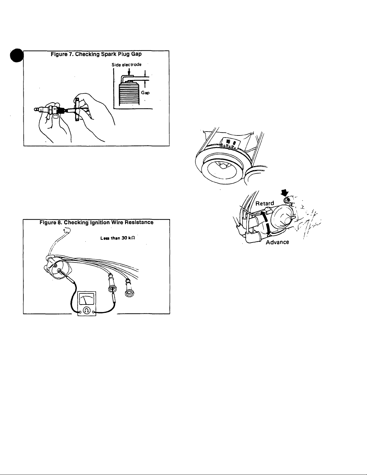
Spark Plugs (Continued)
Use an automotive timing iight to check and adjust
Ignition Timing
ignition timing. A timing mark is provided on the crankshaft
pulley and a degree indicator is also provided. Set timing with
the engine running at no-load as follows:
IGNITION TIMING AT 1860 RPM
21‘BTDC
Figure 9. Ignition Timing
Carefully inspect high tension leads for damage, cracks,
Checking Ignition Wires
burned terminals, proper fit. Measure the resistance of each
wire (Figure 8). Shake the wires during the test.
IGNITION WIRE RESISTANCE
Less than 30,000 ohms
#
Page 8.2-2
Page 84

Part 9
SECTION
9.1
9.2
TABLE OF CONTENTS
TITLE
Standard Battery Charging System
The "DELCO®" Charging System
ENGINE
DC
ELECTRICAL
SYSTEM
NP and IM Series
RECREATIONAL
VEHICLE &
INDUSTRIAL
MOBILE
AC GENERATORS
1.2 Liter, Liquid-Cooled
Gas/Gasoline Engine Modeis
9.3
9.4
9.5
Engine Cranking System
Engine Controi Circuit
Troubleshooting Guide
Page 85

Section 9.1- STANDARD BATTERY CHARGING SYSTEM
A DC ALTERNATOR supplies charging current to the
Components
unit battery during engine operation, as regulated by a DC
VOLTAGE REGULATOR. The circuit is protected by a 30
amp FUSE.
DC Alternator
The belt driven, permanent DC alternator is part of the
engine governor. Maintenance on the DC alternator is limited
to replacement of defective parts. See Part 7, Section 7.1,
"MECHANICAL GOVERNOFT.
Figure 1. Battery Charging System
The solid state DC voltage regulator is housed in an
DC Voltage Regulator
aluminum heat sink. All components are buriedjn an epoxy
resin and the DC regulator is not repairable.
MB
m
Pin 1= charging output to battery (12.5-14.5 volts DC)
Pin 2= charging Input from DC alternator.
Pin 3= charging Inplut from DC alternator.
Pin 4= Not used (charging Indicator lamp)
Pin 5= sensing voltage from battery.
DC regulator
Page 9.1-1
Page 86

Section 9.2- THE "DELCO®" CHARGING SYSTEM
Some industrial-mobile (IM) engine-generators may be
Introduction
equipped with a ’Delcotron®“ battery charging system. This
system utilizes a belt driven DC alternator having an integral
DC voltage regulator.
See Figure 2. During cranking and running operations,
an engine control circuit board delivers battery voltage to the
DC alternator via Wire No. 14, a resistor (R1) and a diode
(D1). This is DC alternator field excitation current. DC alter
nator output (charging) current is delivered to the battery via
Wire No. 13.
DC Alternator Description
See Figure 3. The DC alternator consists primarily of 2
end assemblies, rotor, stator, brushes, slip rings and diodes.
The rotor is supported in the drive end frame by ball bearings
and in the slip ring end frame by roller bearings. Bearings
contain sufficient lubricant to eliminate the need for periodic
lubrication.
DC Alternator Adjustments
No periodic adjustment or maintenance is required on
the DC alternator assembly. Regulator voltage is preset and
no regulator adjustment is needed.
CAUTION: Do NOT attempt to polarize the DC
alternator. Do NOT short or ground any terminals
except as Instructed. Never operate the DC alter
nator with battery out of circuit or with output
terminal open. The DC alternator and the battery
must share the same ground polarity.________________
Testing
GENERAL:
Beforte starting electrical checks, visually inspect all
terminals for clean and tight connections. Check DC alterna
tor mounting bolts and dnve belt tension. Do NOT ground the
No. 2 lead wire. Battery must be in good condition to test the
charging system.
Delcotron Series
System Voltage..................................................12
DELCO® Regulator No......................................1116392
Ground Polarity...................................................Negative
................................................
Figure 3. "Delcotron" DC Alternator
Slip Ring
End Frame
10 SI
Bearing
UNDERCHARGED BATTERY:
1. Connect a DC voltmeter from the DC alternator “BAT"
terminal to ground (Figure 4). Crank the engine and nore the
meter reading. A “zero" reading indicates an open condition
between the “BAT“ connection and the engine control circuit
board.
a. If reading is “zero“ on gaseous fuel unit, test Wire 49
between DC alternator and diode (D1) for open. Check
diode (D1) and resistor (R1), as weil as Wire 14 for open.
b. If unit is a gasoline fueled unit and reading is "zero",
check Wire 49, diode (D1), resistor (R1) and Wire 14
between DC alternator and carburetor fuel valve for open.
Also check Wire 14, between carburetor fuel valve and
engine control circuit board, for open.
Rotor
Stator
Page 87

2, Disconnect the battery ground cable. Connect an ammeter
Testing (Continued)
jin series at “BAT" terminal of DC alternator. See Figure 5.
' Reconnect the battery ground cable. Connect a carbon pile
across the battery. Operate engine at 1860 rpm and adjust
carbon pile as necessary to obtain maximum current output.
a. If ampere output Is within 10 amps of the rated output
stamped on DC alternator case, the alternator is good.
b. If output is NOT within 10 amps of rated output, ground
the field windino tab by inserting a screwdriver into the end
case test hole (Figure 6).
CAUTION; The field winding tab is within 3/4 inch
of the casting surface. Do NOT force screwdriver
deeper than 1 Inch Into end frame._____________________
c. With field winding tab grounded, run engine at 1860 rpm
and again adjust carbon pile to obtain maximum current
output. If output is now within 10 amps of rated output,
check the field winding and check DC voltage regulator
with tester. If output is NOT within 10 amps of rated output,
check field winding, diode trio, rectifier bridge and stator.
OVERCHARGED BATTERY;
Connect a voltmeter from the DC alternator's No. 2
terminal to ground. If reading is “zero“. No. 2 lead circuit is
open. If the battery and the No. 2 lead circuit test good, but
overcharge exists, overhaul the DC alternator. Check field
windings for grounds and shorts. If defective, replace rotor
and test regulator.
Figure 6. Grounding the Field Winding Tab
Insert Screwdriver And Ground Tab
To End Frame By.Touching Screwdriver
To Both Tab and End Frame
End Frame
Hole
#
Page 9.2-2
Page 88

Section 9.3- ENGINE CRANKING SYSTEM
Cranking System Description
See Figure 7, below. Battery power is available to a
large terminal stud of the STARTER CONTACTOR. How
ever, the STARTER CONTACTOR contacts are normally-
open. From the STARTER CONTACTOR, battery voltage is
available to the ENGINE CONTROL circuit board, via Wire
13, a 10 amp CIRCUIT BREAKER, and Wire 15. Major
components of the engine cranking system include the fol
lowing:
D Engine control circuit board.
D Start-Stop switch,
n 10 amp Circuit Breaker.
CD
Starter Contactor,
n Starter.
CD
12 volts Battery.
Figure 7. Engine Cranking System Diagram
Engine Control Circuit Board
See Section 9.4, "ENGINE CONTROL CIRCUIT.
Start-Stop Switch
DESCRIPTION;
See Figure 8. Wires 17 (start), 18 (stop), and 0 (ground)
connect to the start-stop switch terminals.
Setting the switch to "Start" connects the Wire 17 circuit
to Wire 0 (ground). Engine control circuit board action then
initiates engine cranking and startup.
Setting the switch to "Stop" connects the Wire 18 circuit
to ground. The circuit board.then opens its circuit to Wire 14
and engine shutdown occurs.
Operation of the engine cranking system may be briefly
Operational Analysis
descrioed as follows (Figure 7):
1. Battery power is available to the STARTER CONTACTOR,
via the positive battery cable. Battery power is also available
to the ENGINE CONTROL circuit board, via Wire 13, a 10
amp CIRCUIT BREAKER, and Wire 15.
2. When the START-STOP SWITCH is set to “Start", Wire 17
and Pin 3 of the ENGINE CONTROL board are connected to
ground. Circuit board action then delivers 12 volts DC to the
STARTER CONTACTOR coil, via Wire 56. The STARTER
CONTACTOR is energized and its contacts close.
3. On closure of the STARTER CONTACTOR contacts, 12
volts DC is delivered to the STARTER. The engine cranks.
4. When the engine starts, the START-STOP SWITCH is
released and Wire 17 is no longer grounded. Circuit board
action opens the 12 volts DC circuit to Wire 56 and cranking
terminates.
TESTING THE SWITCH:
The start-stop switch can be tested using a volt-ohm-milliammeter (VOM). Set the VOM to its "Rxl" scale and zero
the meter.
D Connect the VOM test leads across the Wire 17 and the
Wire 0 terminal of the switch. With switch at “Start", the
meter should read "continuity": at “Stop", switch should
read “infinity".
D Connect the VOM test leads across the Wire 18 and the
Wire 0 terminals of the switch. Set switch to “Start" and
meter should read “infinity". Set switch to “Stop" and it
should read “continuity”.
10 Amp Circuit Breaker
Refer to Section 9.4, "ENGINE CONTROL CIRCUIT.
Starter Contactor
DESCRIPTION:
The starter contactor (or starter solenoid) is attached to
the engine-generator control panel. See Figure 9.
TESTING THE STARTER CONTACTOR:
If the engine will not crank, the starter contactor can be
tested as follows:
1. Check for normal battery voltage at the large terminal stud
to which the positive battery cable connects.
a. If battery voltage is zero or low, check the battery cable
and the battery.
b. If normal battery voltage is read, go on to Step 2.
Page 9.3-1
Page 89

2. Connect the positive VOM test iead to the large contactor
starter Contactor (Continued)
>
terminal stud to which the starter cabie attaches and the
common VOM test iead to ground. Hold the start-stop switch
at “Start“ and battery voltage should be indicated,
a. If normal battery voltage is indicated, but engine does
not crank, check the contactor to starter cable and the
starter itself.
b. If normal battery voltage is NOT indicated when the
start-stop switch is set to “Start“, go to Step 3.
3. Check for battery voltage at the small starter contactor
terminal to which Wire 56 attaches. When the start-stop
switch Is set to “Start" battery voltage should be indicated,
a. If batte^ voltage is indicated in Step 3 but was NOT
indicated in Step 2, check the starter contactor ground
wire. If ground wire is good, replace the starter contactor,
b. If battery voltage is NOT indicated in Step 3 when the
start-stop switch is set to "Start“, check the following:
(1) Wire 56 between the starter contactor and the engine
control circuit board.
(2) The start-stop switch.
(3) The 10 amp circuit breaker.
(4) Power supply to the engine control circuit board.
springs. Tighten brush screw to 30-35 inch-pounds. Tighten
the hot stud nut to 45-50 inch-pounds.
5. Armature: Check the armature for an open, shorted or
grounded condition with a growler. Hold armature in a vise
while installing or removing the drive assembly. Apply a thin
film of non-conducting grease to the commutator end of the
armature shaft and to the portions of the shaft that contact
the bearings.
STARTER PERFORMANCE TEST:
CAUTION: DO NOT operate the starter continuously for longer than 30 seconds.
_____________________
Use a fully charged, 12 volts battery to test the starter.
Attach the battery’s positive terminal to the starter motor input
stud, and the battery negative terminal to the starter motor
housing. Use a No. 10 (or larger) cable not more than 6 feet
long. Maximum current draw and starter speed should be as
follows:
MAXIMUM NO-LOAD CURRENT DRAW & SPEED
17 amps at 6000-7200 rpm
Battery
RECOMMENDED BATTERY:
When anticipated ambient temperature will consistently
be above 32" F. (O’ C.), use a 12 volts, automotive type
storage battery rated at 70 amp-hours and capable of deliv
ering at least 360 cold cranking amperes.
If ambient temperatures will be below 32" F. (O’ C.), use
a 12 volts battery rated 95 amp-hours and having a cold
cranking capacity of 450 amps.
Starter
DESCRIPTION:
The starter assembly is shown in Figure 10. It is rated 12
volts DC. Never apply any voltage in excess of rated voltage
or magnets in the starter may become demagnetized.
STARTER MOTOR SERVICING:
1. Inspection: Check for adverse wear on all bearings,
gears, shafts, etc. Check the sprino washer for wear, convex
side next to bearing. Add a drop of oil to face of bearing.
2. Thru-Bolts: Tighten thru-bolts to 75 inch-pounds.
3. Drive Cap: Apply a film of SAE #10 oil to the bearings in
the drive cap. During reassembly, the insulating washer must
be placed against the drive cap.
4. Brush Assembly: Brushes and brush springs should be
replaced at each overhaul. Any brush that is worn to 5/16 inch
or less, measured on short side of brush, or that has been in
contact with grease, oil or cleaning fluid, must be replaced.
Assemble brushes with their chamfered side sway from the
BA’TTERY CABLES:
Use of battery cables that are too small in diameter or
too long will result in excessive voltage drop. For best cold
weather starting, voltage drop between the battery and starter
should not exceed 0.12 volt per 100 amperes of cranking
current.
Select battery cables based on total cable length and
prevailing ambient temperatures. Generally, the longer the
cable and the colder the weather, the larger the required
cable diameter. The following chart applies:
CABLE LENGTH (IN FEET)
TTTB
16-20 No. 000
EFFECTS OF TEMPERATURE ON BATTERY:
RECOMMENDED CABLE SIZE
R5r2
RoTO
Battery efficiency is greatly reduced by a decreased
electrolyte temperature, because such low temperatures
have a decided numbing effect on the electrochemical action.
Under high discharge rates (such as cranking), battery volt
age will drop to much lower values in cold temperatures than
in warm temperatures. The freezing point of battery electro
lyte fluid is affected by the state of charge of the electrolyte.
SPECIFIC GRAVITY
1.220
1.200
TTreo
FREEZING POINT
^3rT;"(-37' c. )
-SO' F. (-29' C.)
ITTVi-IO' C.)
Page 9.3-2
Page 90

o
---------
Figure 10. Starter Assembly
0
Q
DRIVE KIT
“B
DRIVE PINION
COMMUTATOR
CAP
O O Ù ^
BRUSH & SPRING KIT
PARTS IN
COMMUTATOR CAP
DRIVE CAP
THRU BOLTS
I
ARMATURE
ASSEMBLY
Page 9.3-3
Page 91

Battery (Continued)
ADDING WATER:
Water is lost from the battery as a result of charging and
^discharging, and must be replaced. If the water is not re
placed and the separator plates become exposed, they may
become permanently sulfated. In addition, the plates cannot
take full part in the battery action unless they are completely
immersed in electrolyte.
CHARGING A BATTERY:
When charging a battery, an explosive gas mixture forms
in each cell. Battery electrolyte fluid is an extremely caustic
sulfuric acid solution that can cause severe burns. For that
reason, the following precautions must be observed;
□
The area must be well ventilated.
Do NOT smoke or break a live circuit near the top of the
□
battery- sparking could cause an explosion.
□
Avoid spillage of battery electrolyte fluid. If spillage oc
curs, flush the affected area with clear water im
mediately.
Wear eye protection when handling a battery.
□
Page 9.3-4
Page 92
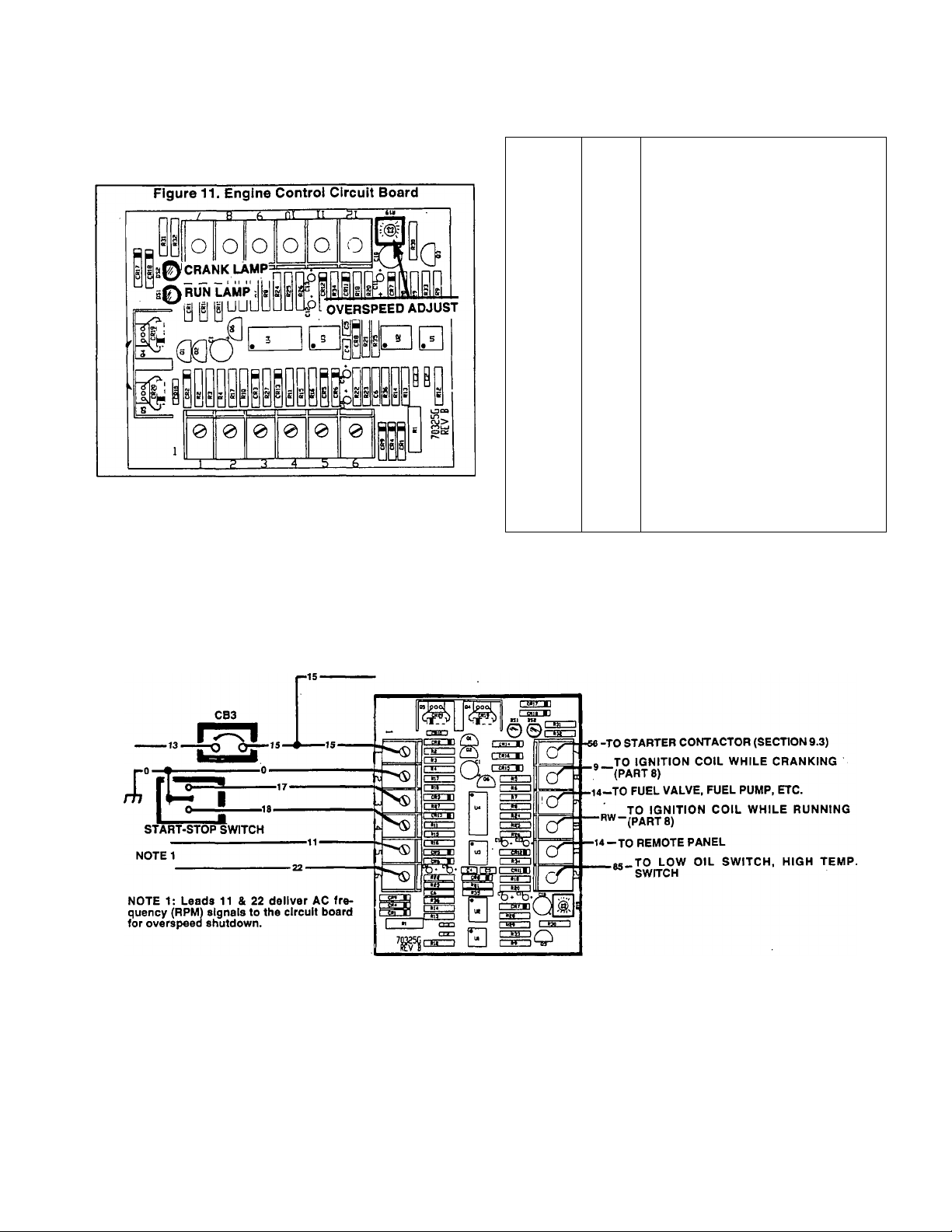
Section 9.4- ENGINE CONTROL CIRCUIT
An engine control circuit board (Figure 11), noused in the
Engine Control Circuit Board
generator control panel, controls engine starting, running and
shutdown functions. A 12 volts DC power supply is delivered
to the board for control of those functions.
Circuit board terminals, connecting wires and a descrip
tion (or function) of the wires is listed in the following chart:
Figure 12. Engine DC Control Circuit
TERMINAL
1 15
2
3
4 18
5&6
7 56
8
9
10
11
12 85
WIRE
11, 22 Frequency (engine speed) signals
DESCRIPTION OR FUNCTION
Breaker protected 12 volts DC power
to operate engine control system.
0
17
9
14 Delivers 12 volts DC to carburetor
RW
14
Common ground.
Engine will crank when this circuit
Engine will shut down when this
from generator AC power leads for
fuel valve, fuel pump and DC alter
Once cranking has ended, battery
power Is delivered to the Ignition
When this circuit Is grounded by
automatic engine shutdown will
is grounded.
circuit is grounded.
automatic engine shutdown.
Crank signal- starter contactor
energizes when circuit board
energizes Wire 56 circuit.
Delivers 12 volts DC to ignition
coil for engine cranking only.
nator for running.
coil via a resistance wire.
Delivers 12 volts DC to a
remote panel only when the
engine is running.
closure of either (a) a low oil
pressure switch, or (b) a high
coolant temperature switch, an
occur
Page 9.4-1
Page 93

Enqine Control Circuit Board (Continued)
See Figure 11 on previous page. The service technician
hould be aware of the following features on the engine
ontrol circuit board:
1. An adjustment potentiometer (R19) is provided to permit
adjustment of the rpm at which an overspeed shut down will
occur.
a. Automatic shutdown should occur when AC frequency
(engine speed) exceeds approximately 69-71 Hertz (2070-
2130 rpm).
b. Adjustment is required whenever the engine control
circuit board is replaced.
2. The circuit board mounts a red crank lamp (LED) which
should turn on when the engine is cranking.
a. A “Lamp On" condition indicates that (a) the Wire 17
circuit has been grounded by start-stop switch action, and
(b) circuit board action has delivered battery voltage to the
Wire No. 56 circuit to initiate cranking.
b. The lamp should go out when the start-stop switch is
released and cranking has terminated.
3. The circuit board mounts a green run iamp (LED).
a. The run lamp should illuminate when circuit board action
has delivered 12 volts DC to the Wire No. 14 circuit (to open
the carburetor fuel valve, and turn on the fuel pump).
b. If the run lamp does NOT turn on during cranking, engine
will not start.
Overspeed Shutdown Adjustment
To adjust the overspeed shutdown setting, proceed as
follows:
1. On the engine control circuit board, turn the OVERSPEED
SHUTDOWN POT counterclockwise until it just contacts its
stop. DO NOT FORCE.
2. Connect an accurate AC frequency meter across the
generator’s AC output leads.
3. Start the engine, let it stabilize and warm up at no-load.
4. SLOWLY increase engine speed until the frequency meter
reads 69-71 Hertz.
5. Hold the throttle at 69-71 Hertz, then SLOWLY turn the
OVERSPEED SHUTDOWN POT clockwise. When the en
gine shuts down, overspeed setting is correct.
Page 9.4-2
Page 94

TEST 1- CHECK
10 AMP CIRCUIT
BREAKER
POSITION
Section 9.5- TROUBLESHOOTING GUIDE
Problem 1. Engine Will Not Crank
CLOSEDhhh^
TEST 2-CHECK
VOLTAGE AT
STARTER
CONTACTOR
TERMINAL
— GOOD ^
TEST 3-CHECK
VOLTAGE AT
STARTER
CONTACTOR
o 1 1
CABLE
1 bHMiNAL
I BAD.
/
V
OPEN
i
CLOSE CIRCUIT
BREAKER
TEST 4-CHECK
BATTERY
CABLES
CLEAN OR REPLACE
TEST 8- CHECK VOLTS O.K.
WIRE 56 VOLTS
AT STARTER
CONTACTOR
IGOOD.
mmm NOW BUTi^h^-
NOT IN CONTACTOR
TEST3
BAD
TEST 5-CHECK
BATTERY
BAD
RECHARGE OR REPLACE
I
TEST 9-CHECK
STARTER ^HGOOCtai^
GROUND
BAD
CLEAN OR REPLACE
GOOD BUT WONT CRANK
■ W
REPLACE
STARTER
CONTACTOR
TEST 7- CHECK
STARTER
MOTOR
BAD
REPAIR OR REPLACE
NO GOOD
TEST 10-CHECK
WIRE 56
I
BAD
I
REPAIR,
RECONNECT
OR REPLACE
GOOD.
BAD
I
REPAIR OR REPLACE
TEST 11-TEST
10 AMP
BREAKER
BAD
L.
iGOO
REPLACE
BAD
I
REPLACE
TEST 12-TEST
START-STOP
SWITCH
-T
__
iGOOC^
I
TEST 13-CHECK POWER SUPPLY
TO CIRCUIT BOARD, IF GOOD
REPLACE ENGINE CONTROL
CIRCUIT BOARD
Page 9.5-1
Page 95

Problem 2. Engine Cranks But Will Not Start
TEST 14-CHECK
FUEL SUPPLY
•l
OUT OF FUEL
REPLENISH FUEL
SUPPLY OR TURN
ON FUEL AS
REQUIRED
TEST 17-CHECK
FUEL PUMP
BAD
I
iO.Kj
GOOD^B^
TEST 15-CHECK
ENGINE CONTROL
CIRCUIT BOARD
WIRE #14
OUTPUT
NO WIRE #14 OUTPUT
i
REPLACE ENGINE
CONTROL
CIRCUIT BOARD
TEST 18-TEST
AUTOMATIC CHOKE
(GASOLINE ONLY)
BAD
iO.Kj
_GOOD^^
TEST 16-CHECK
FUEL VALVE
BAD
i
REPLACE FUEL
VALVE
TEST 19-CHECK
ENGINE
IGNITION
SYSTEM
bId
1 GOODi
GOODk
i
REPLACE BAD PUMP
TEST 20-CHECK
ENGINE FUEL
SYSTEM
iGOOC
i
REPLACE BAD PART(S)
TEST 21-CHECK
ENGINE
MECHANICAL
SYSTEMS
REPAIR OR REPLACE
I
PART(S) AS
NECESSARY
Page 9.5-2
Page 96

Test numbers in the test procedures that follow corre
Introduction
spond to the numbered tests in the troubleshooting flow
charts of Pages 9.5-1 and 9.5-2.
Test 1- Check 10 Amp Circuit Breaker
Position
DISCUSSION:
Battery power must be available to the engine control
circuit board in order for engine cranking to occur. This power
is delivered to the circuit board via Wire 13, the 10 amp circuit
breaker and Wire 15. If the 10 amp breaker is open, cranking
will not be possible.
PROCEDURE:
Check if 10 amp breaker is set to “Off“ or "Open”. If it is
set to “Off" or "Open", reset it to its “On“ or "Closed" position.
Test 5- Check Battery
DISCUSSION:
If the engine will not crank, the unit battery may be
discharged or worn out. ',
PROCEDURE:
Use an automotive type battery hydrometer to test the
battery for (a) state of charge and (b) condition. Follow the
hydrometer manufacturer’s instructions carefully.
State of Charge: If the hydrometer used does not have
a “Percentage of Charge" scale, the following chart may be
used:
SPECIFIC GRAVITY PERCENTAGE OF CHARGE
1.260
1.230
T25S
1.170
ÏÔÜ95
7s^
5ÜÎ5
25^S
RESULTS:
1. If the 10 amp breaker is set to “On" or "Closed", go on to
Test 2.
2. If the 10 amp breaker is set to "Off" or "Open", reset it to
its "On" or "Closed" position.
Test 2- Check Voltage at Starter Contac
tor Battery Terminal
DISCUSSION:
See “reST/NG THE STARTER CONTACTOR' on
Pages 9.3-1 and 9.3-2.
RESULTS:
1. if battery voltage is read at the starter contactor battery
terminal, go on to Test 3.
2. If low or no voltage is indicated at starter contactor battery
terminal, go on to Test 4.
Test 3- Check Voltage at Starter Cable
Terminal
DISCUSSION:
See "TESTING THE STARTER CONTACTOR" on Pages
9.3-1 and 9.3-2.
RESULTS:
1. If low or no voltage is indicated at starter cable terminal
stud of starter contactor when start-stop switch is held at
"Start", go to Test 8.
2. If normal battery voltage is indicated at starter cable
terminal stud of the starter contactor when start-stop switch
Is set to “Start", but the engine will NOT crank, go to Test 6.
Test 4- Check Battery Cables
DISCUSSION:
See "TESTING'THE STARTER CONTACTOR" on Pages
9.3-1 and 9.3-2.
RESULTS:
Clean or replace battery cables as necessary. If battery
cables are good, go to Test 5.
Condition: If the difference in specific gravity between
the highest and lowest reading cells is greater than 0.050 (50
points), the battery should be replaced.
RESULTS:
1. Recharge or replace battery as needed.
Test 6- Check Starter Cable
DISCUSSION:
When the start-stop switch is set to "Start", battery volt
age should be available at the starter motor, indicating that
the starter contactor has energized and its contacts have
closed. If such voltMe was available at the starter contactor
(Test 3) but is NOT available to the starter motor terminal
stud, the starter cable (bètween the contactor and the starter)
is corroded or defective.
PROCEDURE:
Check for battery voltage at the starter motor terminal
stud when the start-stop switch Is set to "Starf.
RESULTS:
1. Clean or replace starter contactor to starter motor
cable as required.
2. If starter cable is good, go to Test 7.
Test 7- Check Starter Motor
DISCUSSION:
Refer to Section 9.3.
Test 8- Check Wire 56 Volts at Starter
Contactor
DISCUSSION:
When the start-stop switch is set to "Start", engine control
circuit board action should deliver battery voltage to the Wire
56 terminal of the starter contactor. The starter contactor
should then become energized and the engine should crank.
This test will determine if battery voltage Is available to
energize the starter contactor and initiate cranking.
Page 9.5-3
Page 97

Test 8- Check Wire 56 Volts at Starter
Contactor (Continued)
ROCEDURE:
m-
See "STARTER CONTACTOR" on Pages 9.3-1 and
9.3-2.
RESULTS:
1. If battery voltage is not Indicated, go to Test 10.
2. If normal battery voltage is Indicated In this test, but was
NOT indicated in Test 3, go to Test 9.
Test 9- Check Starter Contactor Ground
DISCUSSION:
A ground wire connects to one of the smaller starter
contactor terminals and to frame ground. If this wire is open
or if a good ground connection is not available, the starter
contactor will not energize.
PROCEDURE”
Test the starter contactor ground lead for "continuity".
DISCUSSION:
Test 12- Test Start-Stop Switch
When the start-stop switch is set to "Start", switch action
must connect Wire 17 to ground or cranking will not occur, in
addition, when the switch is set to "Stop", Wire 18 must be
connected to ground or engine shutdown will not occur.
PROCEDURE:
1. Connect VOM test leads across the Wire 17 terminal of
switch and the Wire 0 (ground) terminal. Set Switch to "Start"
and meter should read^continuity". Set switch to "Stop" and
meter should read "infinity".
2. Connect the VOM test leads across Wire 18 terminal of
switch and Wire 0 terminal. Set switch to "Start" and VOM
should read "infinity". Set switch to "Stop" and meter should
read "continuity".
RESULTS:
1. Replace the start-stop switch if it fails the test.
2. if switch is good, go to Test 13.
RESULTS:
1. Repair, reconnect or replace the starter contactor ground
wire as necessary.
2. if the ground lead is good, replace the starter contactor.
Test 10. Check Wire 56
ISCUSSION:
if Wire 56, between the engine control circuit board and
the starter contactor, is open, cranking will not occur when
the start-stop switch is set to "Start".
PROCEDURE:
Inspect Wire 56 between the starter contactor and the
engine control circuit board. Test the wire for "continuity".
RESULTS:
1. Repair, reconnect or replace Wire 56 as required.
2. if Wire 56 is good, go to Test 11.
Test 11. Test 10 Amp Circuit Breaker
DISCUSSION:
Battery power must be available to the engine control
circuit board or cranking cannot occur, if the 10 amp breaker
has failed open, battery power will not be available to the
circuit board.
PROCEDURE:
Test the 10 amp breaker for continuity with the breaker
set to "On" or "Closed".
RESULTS:
1. Replace the 10 amp breaker, if it is defective,
if the 10 amp breaker is good, go to Test 12.
Test 13. Check Power Supply to Circuit
Board
DISCUSSION:
In test 8, battery voltage was NOT available to the Wire
56 terminal of the starter contactor. Wire 56 was checked in
Test 10 and it was good. The 10 amp breaker was then tested,
as well as the start-stop switch, and both were good. The
engine control circuit board is left as a suspect.
PROCEDURE:
Connect a DC voltmeter across circuit board Pin #1 and
ground. Battery voltage should be indicated.
RESULTS:
if battery voltage is indicated, replace the engine control
circuit board.
NOTE: Perform Tests 14 through 21 If the enhgine cranks
normally, but will not start.
Test 14. Check Fuel Supply
DISCUSSION:
Orten, the most obvious cause(s) of a problem are overlooked
when troubleshooting.
PROCEDURE:
if the engine cranks but will not start, check the fuel
supply. Also make sure that any shutoff valve(s) in the fuel
supply lines are open.
RESULTS:
1. Replenish fuel supply as necessary.
2. if fuel supply is good but engine will not start, go to Test
15.
Page 9.5-4
Page 98

Test 15. Check Engine Control Circuit
Board Wire #14 Output
DISCUSSiON:
During a startup attempt, when the start-stop switch is
set to “Start“, engine control circuit board action must deliver
battery voitage to the Wire 14 circuit. Wire 14 voitage ener
gizes a fuel solenoid open to aliow fuel flow. On units with
gasoline fuel system, Wire 14 turns on the fuel pump. And,
on units with electronic governor. Wire 14 turns on the gov
ernor circuit.
The fact that the engine cranks when the start-stop
switch is set to "Start“ is adequate verification that battery
power is available to the engine control circuit board.
PROCEDURE:
Use a VOM to check for batteiy voltage at terminal #9
(Wire 14) of the engine control circuit board when the engine
is being cranked. Battery voltage should be indicated.
RESULTS:
1. If battery voltage is indicated, go to Test 16.
2. If battery voltage is NOT indicated, replace the engine
control circuit board.
Test 16. Check Fuel Valve
DISCUSSION:
Units with gasoline fuel system are equipped with a fuel
solenoid valve that is attached to the gasoline carburetor (see
Part 5 of this Manual).
Units with gaseous fuel system have separately mounted
solenoid valve (see Part 6).
The fuel valve MUST open if fuel Is to be introduced to
the engine carburetor.
Test 17. Check Fuel Pump
DISCUSSION:
This check applies to gasoline fuel systems only, since
gaseous fuel systems do not require a fuel pump. The fuel
pump MUST operate on these systems or the engine will not
start.
PROCEDURE:
See Section 5.2 of this Manual.
RESULTS:
1. Replace fuel pump if defective.
2. If fuel pump is good, go to Test 18.
Test 18. Test Automatic Choke
DISCUSSION:
This test applies to gasoline fuel systems only, since
gaseous fuel systems do not require a carburetor choke. The
automatic choke on gasoline units actuates only during en
gine cranking.. Choke operation is terminated at the same
time that cranking ends.
PROCEDURE:
1. Crank the engine. During cranking, the choke solenoid
should pull in about every 2 to 5 seconds.
a. If choke solenoid functions normally, go to Test 19.
b. If choke solenoid does NOT pull in while cranking, go to
Step 2.
2. Try adjusting the choke. See "AUTOMATIC CHOKE AD
JUSTMENT" on Page 5.3-1.
3. Inspect ground wire (No. 0) between choke module and
start-stop switch.
4. Disconnect Wire 90 from choke module and hold it into firm
contact with a clean frame ground. When engine is cranked,
choke solenoid should pull in.
PROCEDURE:
Gasoline Units: Remove the fuel valve from the engine
carburetor. Hold the valve housing into firm contact with a
clean frame ground and set the start-stop switch to "Start".
The valve tip should pull in, indicating that it has been actu
ated to its open position.
Gaseous Fuel Units: Disconnect the inlet and outlet
lines from the gaseous fuel valve. Apply 12 volts DC to the
valve wires and the valve should open. Remove the 12 volts
DC and the valve should close. Use your mouth to blow
through the valve, to verify valve open and closed conditions.
CAUTION: If 12 volts DC Is available to the gas
eous system fuel valve, but valve does not appear
to open, be sure to check gaseous fuel pressure
before rejecting the valve. At pressures in excess
of 14 inches water column (1/2 psi), the valve may
not open.
RESULTS:
1. Replace fuel valve if it is defective.
2. If fuel valve checks good, go to Test 17.
________________________________________
RESULTS:
1. Repair, replace or reconnect ground wire (Step 3) as
necessary.
2. In Step 4, if choke solenoid pulls in when engine is cranked
and Wire 90 is grounded but does NOT puil in otherwise,
replace the choke module.
3. In Step 4, if choke solenoid does not pull in and does not
actuate normally either, replace the choke solenoid.
Test 19. Check Engine Ignition System
DISCUSSION:
If engine cranks normally but won't start, the ignition system
may be at fault.
PROCEDURE:
Test ignition system. See Part 8 of this Manual.
RESULTS:
1. Repair or replace defective ignition system parts as re
quired.
2. If ignition system is functioning normally, go to Test 20.
Page 9.5-5
Page 99

Test 20. Check Engine Fuel System
DISCUSSION:
It the engine cranks normally but will not start, the fuel
Fsystem may be the cause of the problem. Refer to Part 5 for
information on gasoline fuel systems; or Part 6 for gaseous
fuel systems.
RESULTS:
1. Repair or replace defective fuel systems components.
2. If fuel system is functioning properly, go to Test 21.
Test 21- Check Engine Mechanical Sys
tems
DISCUSSION:
failure of the engine to start may be the result of a
mechanical problem in the engine.
PROCEDURE:
See PartT,""ENGINE MECHANICAL". Check engine
compression (see Page 2.1-1).
Page 9.5-6
Page 100

Part 10
OPTIONS
AND
ACCESSORIES
NP and IM Series
RECREATIONAL
VEHICLE &
INDUSTRIAL
SECTION
10.1
10.2
TABLE OF CONTENTS
TITLE
Remote Start-Stop Panels
Remote Gauge Panel
MOBILE
AC GENERATORS
1.2 Liter, Liquid-Cooled
Gas/Gasoline Engine Models
 Loading...