

Generac GP7500E-5943-0, 5943-0 Owner’s Manual
G ®
IIVlODELS:005942-0,
005943-0
Owner'siVlan
7, WattGPSeries
Generator
introduction.............................................................1
ReadthisiVlanualThoroughly.................................1
Safety Rules...........................................................1
StandardsIndex.............................................................3
Generalinformation................................................4
1.1 Unpacking......................................................................4
1.1.1 Accessory Box..................................................4
1.2 Assembly.......................................................................4
1.2.1 Assemblingthe AccessoryKit............................4
1.2.2 BatteryCableConnection(ElectricStart Only)....4
Operation................................................................4
2.1 Knowthe Generator.......................................................4
2.2 Hourmeter......................................................................6
2.3 CordSets andConnectionPlugs....................................6
2.3.1 120 VAC,20 Amp,DuplexReceptacle...............6
2.3.2 120/240VAC,30 Amp, Receptacle....................6
2.4 Howto Usethe Generator..............................................6
2.4.1 Groundingthe Generator....................................7
2.4.2 ConnectingElectricalLoads...............................7
2.5 Don'tOverloadthe Generator..........................................7
2.6 WattageReferenceGuide...............................................7
2.7 BeforeStartingtheGenerator.........................................8
2.7.1 Adding EngineOil..............................................8
2.7.2 Adding Gasoline.................................................8
2.8 Starting Pull StartEngines..............................................8
2.9 Starting ElectricStart Engines........................................9
2.10 Stoppingthe Engine.....................................................10
2.11 Low Oil LevelShutdownSystem..................................10
2.11.1 SensingLow Oil Level......................................10
2.12 Chargingthe Battery(ElectricStart Units Only).............10
Maintenance.........................................................10
3.1 MaintenanceSchedule.................................................10
3.2 ProductSpecifications..................................................11
3.2.1 GeneratorSpecifications..................................11
3.2.2 EngineSpecifications.......................................11
3.2.3 EmissionsInformation.....................................11
3.3 GeneralRecommendations...........................................11
3.3.1 GeneratorMaintenance....................................11
3.3.2 ToCleanthe Generator.....................................11
3.3.3 EngineMaintenance.........................................11
3.3.4 CheckingOil Level...........................................11
3.3.5 Changingthe Oil..............................................12
3.3.6 Replacingthe SparkPlug.................................12
3.3.7 BatteryReplacement........................................12
3.4 ServiceAir Cleaner.......................................................12
3.5 ValveClearance............................................................13
3.6 General........................................................................13
3.5 Long TermStorage....................................................... 13
3.6 OtherStorageTips.......................................................13
Troubleshooting....................................................14
4.1 TroubleshootingGuide..................................................14
Notes....................................................................15
Warranty...............................................................16
MANUALDELPROPIETARIO.............................19
MANUELD'ENTRETIEN......................................39
INTRODUCTION
Thankyou for purchasingthis model by GeneracPowerSystems,
Inc. This model is a compact, high performance, air-cooled,
engine driven generatordesigned to supply electrical power to
operateelectrical loads where no utility power is availableor in
placeof utility dueto apoweroutage.
BEADTHiSMANUALTHOROUGHLY
If any portion of this manual is not understood, contact the
nearest Authorized Dealer for starting, operating and servicing
procedures.
The operator is responsiblefor proper and safe use of the
equipment.We strongly recommendthat the operator read this
manualandthoroughlyunderstandall instructionsbeforeusingthe
equipment.Wealsostronglyrecommendinstructingother usersto
properlystart andoperatethe unit.This preparesthem ifthey need
to operatetheequipmentin anemergency.
Thegeneratorcan operatesafely,efficiently andreliablyonly if it
is properlylocated, operatedand maintained.Beforeoperatingor
servicingthe generator:
• Becomefamiliar with and strictly adhereto all local, stateand
nationalcodes andregulations.
• Study all safety warnings in this manual and on the product
carefully.
• Becomefamiliarwith this manualandthe unit beforeuse.
Themanufacturercannot anticipateevery possible circumstance
that might involvea hazard.Thewarnings inthis manual,and on
tags and decals affixedto the unit are, therefore,not all inclusive.
If usinga procedure,work method oroperatingtechniquethat the
manufacturerdoes not specifically recommend,ensurethat it is
safe for others. Also makesure the procedure,work methodor
operatingtechniqueutilizeddoes not renderthe generatorunsafe.
THE INFORMATIONCONTAINEDHEREIN WAS BASED ON
MACHINESIN PRODUCTIONAT THE TIME OF PUBLICATION.
GENERACRESERVESTHERIGHTTOMODIFYTHISMANUALAT
ANYTIME.
SAFETYRULES
Throughoutthis publication,and ontags anddecals affixedto the
generator,DANGER,WARNING,CAUTIONand NOTEblocks are
usedto alert personnelto special instructionsabout a particular
operation that may be hazardous if performed incorrectly or
carelessly. Observe them carefully. Their definitions are as
follows:
iNDICATESA HAZARDOUSSiTUATiONORACTIONWHICH,IF
NOTAVOIDED,WiLLRESULTiN DEATHORSERIOUSiNJURY.
Indicatesa hazardoussituationor actionwhich,if not
avoided, couldresultin deathorseriousinjury.
,ACAUTION!
Indicatesa hazardoussituationoraction which,if not
avoided, couldresultin minorormoderateinjury.
NOTE:
Notescontain additionalinformationimportantto aprocedure
and will be found within theregular textbodyof thismanual.
These safety warnings cannot eliminatethe hazards that they
indicate. Common sense and strict compliancewith the special
instructionswhileperforming theaction orserviceareessentialto
preventingaccidents.
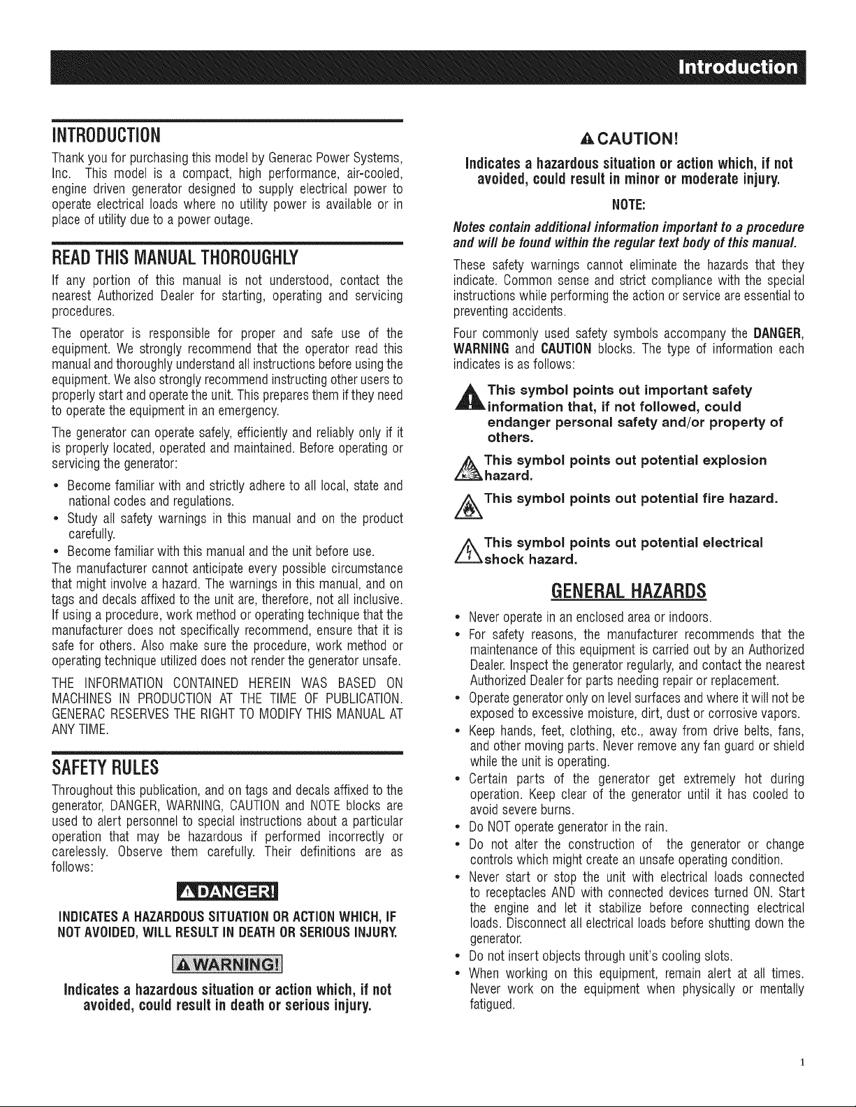
Four commonly used safety symbols accompanythe DANGER,
WARNINGand CAUTIONblocks. The type of information each
indicatesis asfollows:
,_This symbol points out important safety
information that, if not followed, could
endanger personal safety and/or property of
others.
This symbol points out potential explosion
hazard.
i/_This symbol points out potential fire hazard.
i/_This symbol points out potential electrical
shock hazard.
GENERAL HAZARDS
• Neveroperatein anenclosedareaor indoors.
• For safety reasons, the manufacturer recommends that the
maintenanceof this equipmentis carried outby an Authorized
Dealer.Inspectthe generatorregularly,and contactthe nearest
AuthorizedDealerfor parts needingrepairor replacement.
• Operategeneratoronly on levelsurfacesandwhereit will notbe
exposedto excessivemoisture,dirt, dust orcorrosivevapors.
• Keephands, feet, clothing, etc., away from drive belts, fans,
and other moving parts. Neverremoveany fan guardor shield
whilethe unit is operating.
• Certain parts of the generator get extremely hot during
operation. Keep clear of the generator until it has cooled to
avoidsevereburns.
• Do NOToperategeneratorinthe rain.
• Do not alter the construction of the generator or change
controlswhich might createan unsafeoperatingcondition.
• Neverstart or stop the unit with electrical loads connected
to receptaclesAND with connecteddevicesturned ON. Start
the engine and let it stabilize before connecting electrical
loads. Disconnect all electricalloads beforeshutting downthe
generator.
• Do notinsert objectsthrough unit's cooling slots.
• When working on this equipment, remain alert at all times.
Never work on the equipment when physically or mentally
fatigued.
* Neveruse the generatoror anyof its parts as a step. Stepping
on the unit can stress and break parts, and may result in
dangerousoperating conditions from leakingexhaust gases,
fuel leakage,oil leakage,etc.
* Onelectricstart models, disconnectthe POSITIVE(+) battery
cable from the enginestarter ORthe NEGATIVE(-) battery
cable from the battery terminal, whichever is easier, before
transportingthe generator.
NOTE:
This generator is equippedwith a spark arrestor muffler. The
spark arrestor must be maintained in effective working order
by the owner/ operator. In the State of California, a spark
arrestor is required by law (Section 4442 of the California
PublicResourcesCode).Otherstates may have similar laws.
Federal lawsapply on federal lands.
EXHAUST & LOCATIONHAZARDS
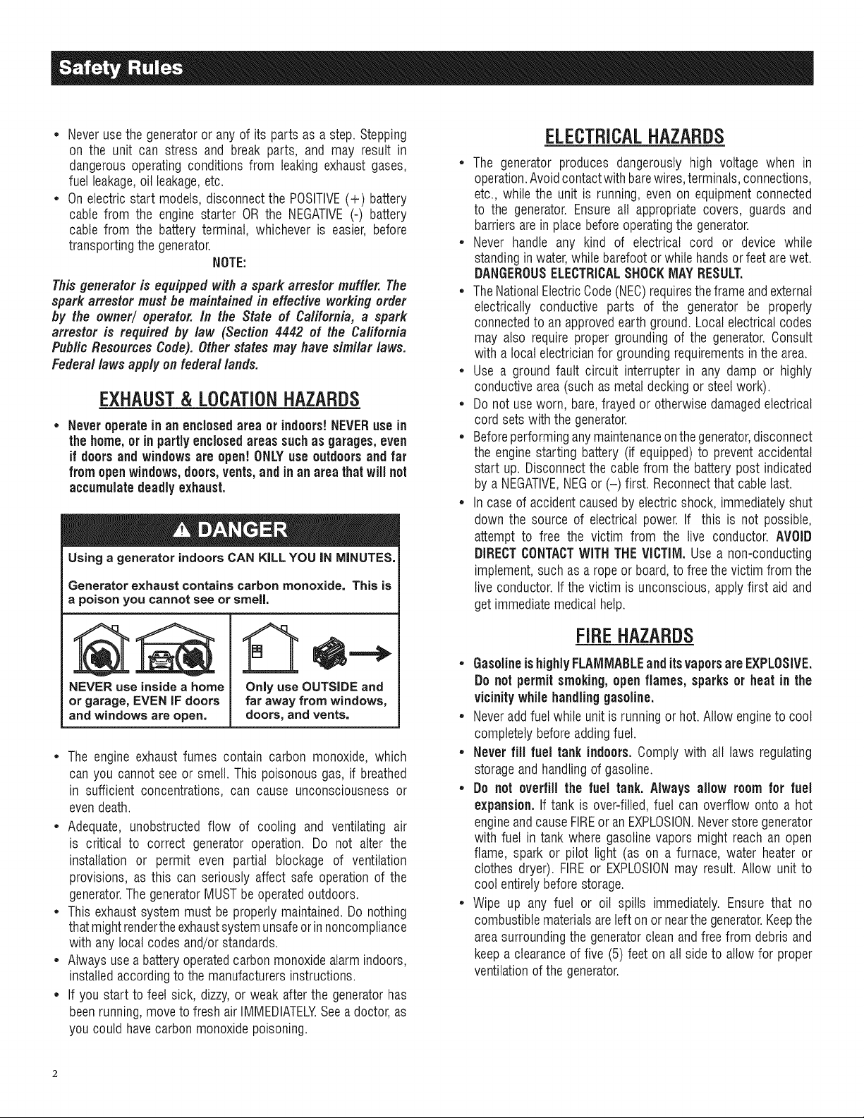
• Neveroperate in an enclosed areaor indoors!NEVERuse in
the home,or in partlyenclosedareassuchas garages, even
if doors and windowsare open! ONLYuse outdoors and far
fromopenwindows,doors, vents,andin anarea thatwill not
accumulatedeadly exhaust.
Using a generator indoors CAN KiLL YOU iN MINUTES.
Generator exhaust contains carbon monoxide. This is
a poison you cannot see or smell,
ELECTRICALHAZARDS
* The generator produces dangerously high voltage when in
operation.Avoidcontactwith barewires,terminals,connections,
etc., while the unit is running,even on equipmentconnected
to the generator. Ensureall appropriate covers, guards and
barriersarein placebeforeoperatingthe generator.
* Never handle any kind of electrical cord or device while
standinginwater,while barefootorwhile handsor feetarewet.
DANGEROUSELECTRICALSHOCKMAYRESULT.
* TheNationalElectricCode(NEC)requirestheframe andexternal
electrically conductive parts of the generator be properly
connectedto an approvedearthground.Local electricalcodes
may also requireproper groundingof the generator.Consult
with a local electricianfor groundingrequirementsin thearea.
* Use a ground fault circuit interrupter in any damp or highly
conductivearea(such as metaldecking or steelwork).
* Do not useworn, bare,frayed orotherwisedamagedelectrical
cord setswith the generator.
* Beforeperforminganymaintenanceonthegenerator,disconnect
the enginestarting battery (if equipped)to preventaccidental
start up. Disconnectthe cablefrom the batterypost indicated
by aNEGATIVE,NEGor (-) first. Reconnectthatcable last.
* In caseof accidentcausedby electricshock, immediatelyshut
down the source of electrical power.If this is not possible,
attempt to free the victim from the live conductor. AVOID
DIRECTCONTACTWITH THEVICTIM. Usea non-conducting
implement,such as a ropeor board,to freethevictim from the
live conductor.If the victim is unconscious, apply first aid and
getimmediatemedical help.
NEVER use insidea home
or garage, EVEN IF doors
and windows are open.
* The engine exhaust fumes contain carbon monoxide, which
can you cannot see or smell. This poisonousgas, if breathed
in sufficient concentrations, can cause unconsciousness or
evendeath.
* Adequate, unobstructed flow of cooling and ventilating air
is critical to correct generator operation. Do not alter the
installation or permit even partial blockage of ventilation
provisions, as this can seriously affect safe operationof the
generator.ThegeneratorMUSTbeoperatedoutdoors.
* Thisexhaustsystem must be properlymaintained.Do nothing
that mightrendertheexhaustsystemunsafeorinnoncompliance
with any localcodes and/or standards.
* Alwaysusea battery operatedcarbonmonoxidealarmindoors,
installedaccordingto themanufacturersinstructions.
* If you start to feet sick, dizzy,or weak afterthe generatorhas
beenrunning,moveto freshair IMMEDIATELYSeea doctor,as
you couldhavecarbonmonoxidepoisoning.
Only use OUTSIDE and
far away from windows,
doors, and vents.
FIREHAZARDS
• GasolineishighlyFLAMMABLEand itsvaporsare EXPLOSIVE.
Do notpermitsmoking,open flames, sparksor heat in the
vicinitywhilehandlinggasoline.
• Neveraddfuel whileunit isrunning or hot.Allow engineto cool
completelybeforeaddingfuel.
• Never fill fuel tank indoors, Comply with all laws regulating
storageand handlingof gasoline.
• Do not overfill the fuel tank. Always allow roomfor fuel
expansion. If tank is over=filled,fuel can overflow onto a hot
engineandcauseFIREor an EXPLOSION.Neverstoregenerator
with fuel in tank where gasolinevapors might reach an open
flame, spark or pilot light (as on a furnace, water heateror
clothes dryer). FIREor EXPLOSIONmay result. Allow unit to
cool entirelybeforestorage.
• Wipe up any fuel or oil spills immediately.Ensure that no
combustiblematerialsareleft on ornearthegenerator.Keepthe
areasurroundingthe generatorcleanandfree from debrisand
keepa clearanceof five (5) feet onall side to allow for proper
ventilationof the generator.
* Do not insert objectsthrough unit's coolingslots.
* Do not operatethe generatorif connected electrical devices
overheat,if electricaloutputislost, if engineorgeneratorsparks
or ifflames orsmokeare observedwhileunit is running.
* Keepafire extinguishernearthe generatoratall times.
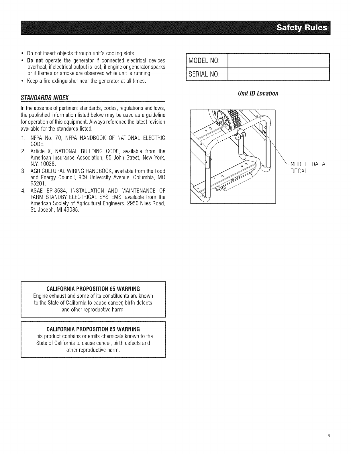
MODELNO:
SERIALNO:
STAtVDARDS/#DEX
Intheabsenceof pertinentstandards,codes,regulationsandtaws,
the publishedinformationlistedbelowmay be usedas aguideline
foroperationof this equipment.Alwaysreferencethelatestrevision
availablefor the standardslisted.
1. NFPANo. 70, NFPAHANDBOOKOF NATIONALELECTRIC
CODE.
2. Article X, NATIONALBUILDINGCODE, available from the
American InsuranceAssociation, 85 John Street, NewYork,
N.Y 10038.
3. AGRICULTURALWIRINGHANDBOOK,availablefrom the Food
and EnergyCouncil, 909 UniversityAvenue, Columbia, MO
65201.
4. ASAE EP-3634, INSTALLATIONAND MAINTENANCEOF
FARMSTANDBYELECTRICALSYSTEMS,availablefrom the
AmericanSocietyof AgriculturalEngineers,2950 NilesRoad,
St. Joseph, MI 49085.
UnitIBLocation
DATA
DECAL
CALIFORNIAPROPOSITION65 WARNING
Engineexhaustandsomeof itsconstituentsareknown
to theStateof Californiato causecancer,birth defects
andotherreproductiveharm.
CALIFORNIAPROPOSITION65 WARNING
This productcontains or emitschemicalsknown tothe
Stateof Californiato causecancer,birth defectsand
otherreproductiveharm.
1.1 UNPACKING
• Removeall packagingmaterial.
• Removeseparateaccessorybox.
• Removethegeneratorfrom carton.
1.1.1 ACCESSORYBOX
Checkall contents.If anyparts aremissing or damaged,locatean
authorizeddealerat 1-888-436-3722.
e
1 - Owner's Manual • 1 - Handle Assembly
e
1 - Liter Oil SAE 30 • 1 - Frame Foot
e
2 - Never-Flat Wheels • 1 - Battery Charger (electric
start only)
1 - Hardware Bag (containing the following):
• 2-Rubber Feet • 2-M8 Bolt (Long)
• 2-1/2" Axle Pins • 2-M8 Bolts (Short)
• 2-Cotter Pins • 2-M8 Acorn Nut
• 2-1/2" FlatWashers • 4-Hex FlangedM8 Nuts
• 2-Short Bolts • 2-Lock Washers
• 2-FlangeNuts (electricstart only)
1.2 ASSEMBLY
Thegeneratorrequiressomeassemblypriorto usingit. Ifproblems
arise when assemblingthe generator,pleasecall the Generator
Hetplineat 1-888-77LOWES.
1.2.1 ASSEMBLINGTHEACCESSORYKIT
The wheels are designed into the unit to greatly improve the
portability ofthe generator.
You will needthe following tools to properlyinstall the accessory
kit.
• NeedleNosePliers
• Ratchetanda 13mm (1/2") socket
• 13mm (1/2") box wrench
NOTE:
The wheels are not intendedfor over-the-road use.
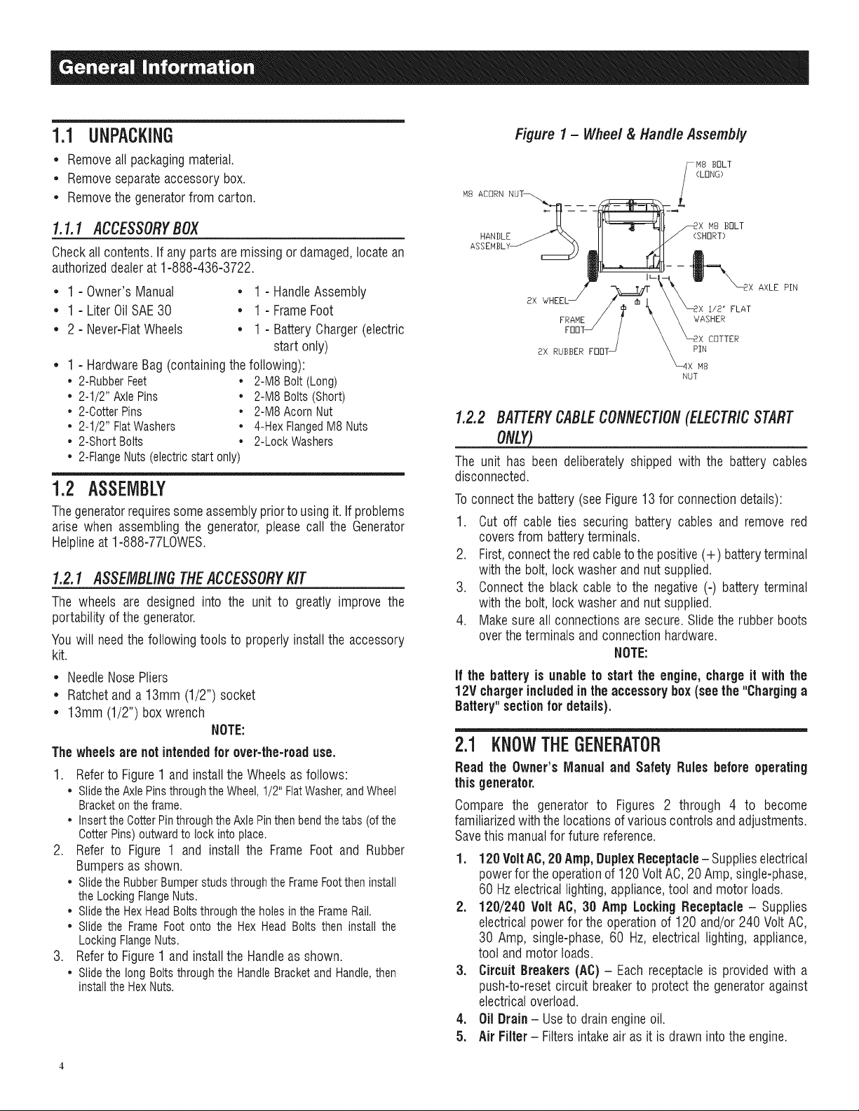
1. Refer to Figure 1 and install the Wheels as follows:
• Slidethe AxlePinsthroughthe Wheel,1/2" FlatWasher,andWheel
Bracketon the frame.
• Insertthe CotterPinthroughthe AxlePinthenbend thetabs (ofthe
OotterPins) outward to lock into place.
2. Refer to Figure 1 and install the Frame Foot and Rubber
Bumpers as shown.
• Slidethe RubberBumperstuds throughthe FrameFootthen install
the LockingFlangeNuts.
• Slidethe HexHeadBoltsthrough the holesin the FrameRail.
• Slide the Frame Foot onto the Hex Head Bolts then install the
LockingFlangeNuts.
3. Refer to Figure 1 and install the Handle as shown.
• Slidethe long Bolts through the HandleBracketand Handle,then
installthe HexNuts.
Figure 1- Wheel & Handle Assembly
AXLE PIN
2X
FRANE WASHER
NUT
i/£ _ FLAT
COTTER
PIN
N8
1.2.2 BATTERYCABLECONNECTION(ELECTR/CSTART
ONLY)_
The unit has been deliberatelyshipped with the battery cables
disconnected.
Toconnectthe battery(seeFigure13 for connectiondetails):
1. Cut off cable ties securing battery cables and remove red
coversfrom batteryterminals.
2. First,connecttheredcableto thepositive(+) batteryterminal
with the bolt, lock washerandnut supplied.
3. Connectthe black cable to the negative(-) batteryterminal
with the bolt, lock washerandnut supplied.
4. Makesure allconnectionsare secure.Slidethe rubber boots
overtheterminals and connectionhardware.
NOTE:
If the battery is unable to start the engine,charge it with the
12V chargerincludedinthe accessory box(seethe "Charginga
Battery" section for details).
2.1 KNOWTHEGENERATOR
Read the Owner'sManual and Safety Rules before operating
this generator.
Compare the generator to Figures 2 through 4 to become
familiarizedwiththelocations of variouscontrolsandadjustments.
Savethis manualfor future reference.
1. 120 VoltAC,20 Amp, DuplexReceptacle- Supplieselectrical
powerfor theoperationof 120Volt AC,20 Amp,single-phase,
60 Hzelectricallighting,appliance,tool and motor loads.
2. 120/240 VoltAC, 30 Amp LockingReceptacle - Supplies
electricalpowerfor the operationof 120 and/or240 Volt AC,
30 Amp, single-phase, 60 Hz, electrical lighting, appliance,
tool andmotor loads.
3. Circuit Breakers(AC)- Eachreceptacleis providedwith a
push-to-reset circuit breakerto protectthe generatoragainst
electricaloverload.
4. Oil Drain- Useto drainengineoil.
5. AirFilter - Filtersintakeair as it isdrawn intothe engine.

6, ChokeKnob- Usedwhen startinga coldengine.
7, FuelTank- SeegeneratorSpecificationsfor tank capacity.
8, GroundingLug- Groundthe generatorto an approvedearth
groundhere.See"GroundingtheGenerator"for details.
g, Run/StopSwitch - Controls the operation of the generator
(pull start models).
CA,Start Switch - Used to start engine from the starter motor
(electricstart modelsonly).
10, Muffler - Quietsthe engine.
Figure2 - Centre/Panel
Figure3 - Generator Controls
Figure 4 - Generator Controls
11. Handle - Pivot and retract for storage. Press the spring-
loadedbuttonto move handles.
12, GasCap- Fuelfill location.
13. FuelGauge- Showsfuel levelin tank.
14. OilFill - Addoil here.
15, Recoil Starter - Useto start enginemanually.
16. FuelShut Off - Valvebetweenfueltank andcarburetor.
17. Battery Charger Input - Thisreceptacleallowsthe capability
to recharge the 12 volt DO storage battery provided with
the 12 Volt Adaptor Plug Chargerwhich is included in the
Accessory Box. Locatedbehindthe battery chargerinput is
a 1.50 Amp in-linefuse which is inside the control panelto
protectthe battery(electricstart modelsonly).
18. Battery - Powersthe electric starter (electric start models
only).
lg. Hourmeter- Trackshoursof operation.
2.2 HOURMETER
The Hourmeter tracks hours of operation for scheduled
maintenance:
Therewill be a"CHGOIL"messageevery100 hours.Themessage
will flash one hour before and one hour after each 100 hour
interval,providinga two hourwindow to perform service.
This messagewill actuallybeginflashing at 99 hoursand disable
itselfat 101 hoursagain,providingatwo hourwindow to perform
the service.
Every200 hours the "SVC"icon on the lower left hand corner of
the displaywill flash. Themessagewill flash one hourbeforeand
onehourafter each200 hourintervalprovidingatwo hourwindow
to performservice.
Whenthe hour meter is inthe FlashAlert mode,the maintenance
message will always alternate with elapsedtime in hours and
tenths. The hours wilt flash four times, then alternate with the
maintenancemessagefourtimes untilthe meterresetsitself.
• 100 hours- CHGOIL-- OilChangeInterval(Every100 hrs)
Note:
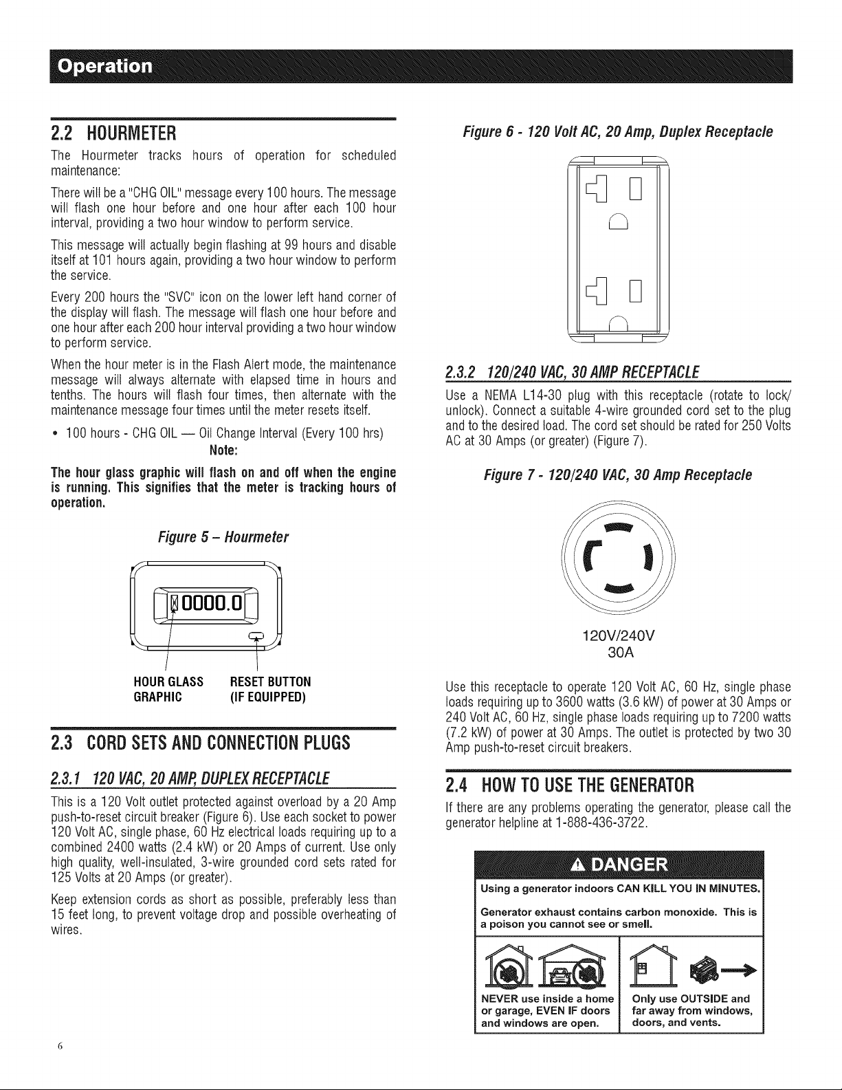
Figure 6 - 120 Volt AC, 20 Amp, Duplex Receptacle
D
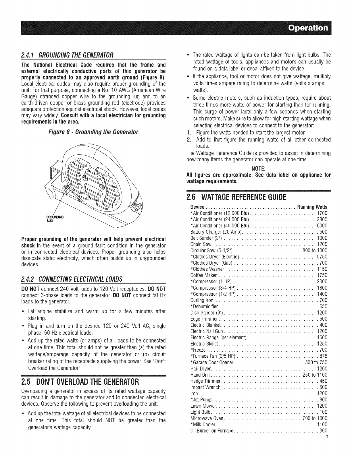
2.3.2 120/240 V4C,30AMPRECEPTACLE
Use a NEMA L14-30 plug with this receptacle (rotate to lock/
unlock). Connecta suitable4-wire groundedcord set to the plug
andto thedesiredtoad.Thecordset shouldbe ratedfor 250 Volts
ACat 30Amps (or greater)(Figure7).
The hour glassgraphicwill flash on and off when the engine
is running.This signifiesthat the meter is tracking hoursof
operation.
Figure 5 - Hourmeter
oooo.oq
I!
i i
HOURGLASS RESETBUTTON
GRAPHIC (IF EQUIPPED)
2.3 CORDSETSANDCONNECTIONPLUGS
2.3.1 120V4C,20 AMP,DUPLEXRECEPTACLE
This is a 120 Voltoutlet protectedagainst overloadby a 20 Amp
push-to-resetcircuit breaker(Figure6). Useeach socketto power
120 Volt AC, singlephase,60 Hzelectricalloadsrequiringup to a
combined 2400 watts (2.4 kW) or 20 Amps of current.Use only
high quality,welt-insulated,3-wire groundedcord sets ratedfor
125 Volts at20 Amps (orgreater).
Keep extensioncords as short as possible,preferably less than
15 feet long, to preventvoltage drop and possibleoverheatingof
wires.
Figure 7 - 120/240 VAC, 30 Amp Receptacle
120V/240V
30A
Use this receptacleto operate120 Volt AC,60 Hz, single phase
loadsrequiringup to 3600 watts (3.6kW) of power at 30 Ampsor
240 Volt AC,60 Hz,singlephaseloadsrequiringup to 7200 watts
(7.2 kW) of powerat 30 Amps.Theoutlet is protectedby two 30
Amp push-to-resetcircuit breakers.
2.4 HOWTOUSETHEGENERATOR
If there are any problems operatingthe generator,pleasecall the
generatorhetplineat 1-888-436-3722.
Using a generator indoors CAN KILL YOU iN MINUTES.
Generator exhaust contains carbon monoxide. This is
a poison you cannot see or smell
NEVER use inside a home
or garage, EVEN IF doors
and windows are open.
Only use OUTSIDE and
far away from windows,
doors, and vents.
2.4.1 GROUNDINGTHEGENERATOR
The National Electrical Code requires that the frame and
external electrically conductive parts of this generator be
properlyconnectedto an approvedearth ground (Figure 8).
Local electrical codes may also requireproper groundingof the
unit. Forthatpurpose, connectinga No. 10 AWG(AmericanWire
Gauge) stranded copper wire to the grounding lug and to an
earth-driven copper or brass grounding rod (electrode)provides
adequateprotectionagainstelectricalshock. However,local codes
may vary widely. Consultwith a localelectricianfor grounding
requirementsin the area.
Figure8 - Groundingthe Generator
GROL_
LUG
Proper groundingof the generatorwill help preventelectrical
shockin the event of a ground fault condition in the generator
or in connected electrical devices. Proper groundingalso helps
dissipate static electricity,which often builds up in ungrounded
devices.
2.4.2 CONNECTINGELECTR/CALLOADS
DONOTconnect240 Volt loadsto 120Volt receptacles.DO NOT
connect 3-phaseloads to the generator.DO NOTconnect 50 Hz
loadsto thegenerator.
• Let engine stabilize and warm up for a few minutes after
starting.
• Plug in and turn on the desired 120 or 240 Volt AO, single
phase,60 Hzelectrical loads.
• Addup the ratedwatts (or amps) of all loadsto be connected
at onetime. Thistotal should not begreaterthan (a) the rated
wattage/amperagecapacity of the generator or (b) circuit
breakerratingof thereceptaclesupplyingthe power.See"Don't
Overloadthe Generator".
2.5 DON'TOVERLOADTHEGENERATOR
Overloadinga generator in excessof its ratedwattage capacity
can resultin damageto the generatorandto connectedelectrical
devices.Observethefollowing to preventoverloadingthe unit:
• Addupthetotal wattageofall electricaldevicesto be connected
at one time. This total should NOT be greater than the
generator'swattagecapacity.
• The ratedwattageof lights can betaken from light bulbs.The
ratedwattageof tools, appliancesand motors can usually be
foundon a data labelor decalaffixedto the device.
• If the appliance,tool or motor does not give wattage,multiply
voltstimes ampereratingto determinewatts (voltsx amps =
watts).
• Some electric motors, such as inductiontypes, require about
threetimes morewatts of powerfor startingthan for running.
This surge of power lasts only a few seconds when starting
suchmotors. Makesureto allowfor highstartingwattagewhen
selectingelectrical devicesto connectto the generator:
1. Figurethe watts neededto start the largestmotor.
2. Add to that figure the running watts of all other connected
loads.
TheWattageReferenceGuideis providedto assist in determining
how manyitemsthegeneratorcan operateat onetime.
NOTE:
All figures are approximate. See data label on appliance for
wattage requirements.
2.6 WATTAGEREFERENCEGUIDE
Device................................... RunningWatts
*AirConditioner(12,000Btu).......................... 1700
*AirConditioner(24,000Btu).......................... 3800
*AirConditioner(40,000Btu).......................... 6000
BatteryCharger(20Amp).............................. 500
BeltSander(3").................................... 1000
ChainSaw........................................ 1200
CircularSaw(6-1/2")........................... 800to 1000
*ClothesDryer(Electric)............................. 5750
*ClothesDryer(Gas)................................. 700
*ClothesWasher................................... 1150
CoffeeMaker...................................... 1750
*Compressor(1HP)................................. 2000
*Compressor(3/4HP)............................... 1800
*Compressor(1/2HP)............................... 1400
CurlingIron......................................... 700
*Dehumidifier....................................... 650
DiscSander(9").................................... 1200
EdgeTrimmer....................................... 500
ElectricBlanket...................................... 400
ElectricNailGun.................................... 1200
ElectricRange(perelement)........................... 1500
ElectricSkillet...................................... 1250
*Freezer............................................ 700
*FurnaceFan(3/5HP)................................ 875
*GarageDoorOpener............................ 500to 750
HairDryer......................................... 1200
HandDrill.................................... 250to 1100
HedgeTrimmer...................................... 450
ImpactWrench...................................... 500
Iron.............................................. 1200
*JetPump......................................... 800
LawnMower....................................... 1200
LightBulb.......................................... 100
MicrowaveOven............................... 700to 1000
*MilkCooler....................................... 1100
OilBurneronFurnace................................. 300
"7
OilFiredSpace Heater(140,000 Btu) ..................... 400
OilFiredSpace Heater(85,000 Btu) ...................... 225
OilFiredSpace Heater(30,000 Btu) ...................... 150
*Paint Sprayer,Airless(1/3 HP)......................... 600
PaintSprayer,Airless (handheld)......................... 150
Radio......................................... 50 to 200
*Refrigerator........................................ 700
SlowCooker........................................ 200
*SubmersiblePump (1-1/2 HP) ........................ 2800
*SubmersiblePump (1 HP) ........................... 2000
*Submersible Pump(1/2 HP).......................... 1500
*Sump Pump................................. 800 to 1050
*Table Saw (10") ............................. 1750 to 2000
Television..................................... 200 to 500
Toaster..................................... 1000 to 1650
WeedTrimmer ...................................... 500
* Allow 3 times the listedwatts for startingthese devices.
2.7 BEFORESTARTINGTHEGENERATOR
Priorto operatingthe generator,engineoil and gasolinewill need
to beadded,asfollows:
2,7,1 IIL #/tVGENG/NEO/L
All oil should meet minimum American PetroleumInstitute (API)
Service Class SJ, SL or better.Use no special additives. Select
the oil's viscosity grade according to the expected operating
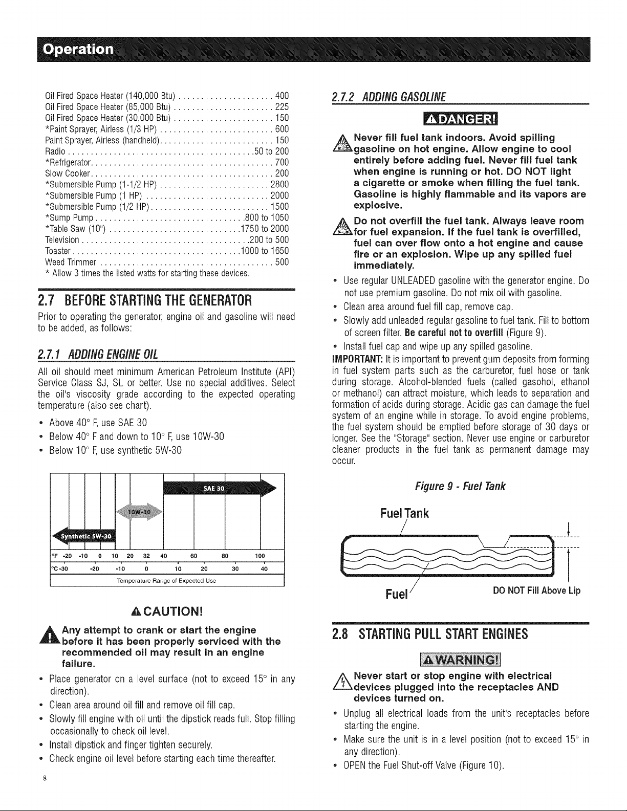
temperature(also seechart).
• Above40° F,useSAE30
• Below40° Fand down to 10° F,use10W-30
• Below10° F,usesynthetic5W-30
2.7,2 IIDO/NGGASOL/NE
Never fill fuel tank indoors. Avoid spilling
gasoline on hot engine. Allow engine to cool
entirely before adding fuel. Never fill fuel tank
when engine is running or hot. DO NOT light
a cigarette or smoke when filling the fuel tank.
Gasoline is highly flammable and its vapors are
explosive.
Do not overfill the fuel tank. Always leave room
for fuel expansion, if the fuel tank is overfiJJed,
fuel can over flow onto a hot engine and cause
fire or an explosion. Wipe up any spilled fuel
immediately.
• UseregularUNLEADEDgasolinewith the generatorengine.Do
not usepremiumgasoline.Do notmix oil with gasoline.
• Cleanareaaroundfuelfill cap, removecap.
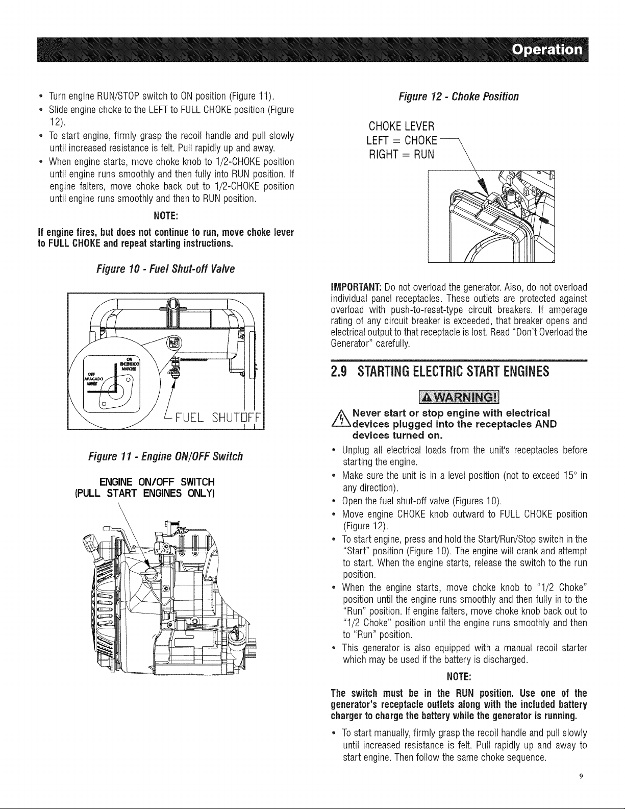
• Slowlyaddunleadedregulargasolineto fueltank. Fillto bottom
of screenfilter.Be carefulnotto overfill (Figure9).
• Installfuel cap andwipe up any spilledgasoline.
IMPORTANT."Itis importantto preventgum depositsfrom forming
in fuel system parts such as the carburetor,fuel hose or tank
during storage. Alcohol-blendedfuels (called gasohol, ethanol
or methanol)can attract moisture, which leadsto separationand
formationof acidsduringstorage.Acidic gas can damagethefuel
system of an enginewhile in storage.Toavoid engineproblems,
the fuel system should be emptiedbefore storage of 30 days or
longer.Seethe "Storage"section. Neveruseengineor carburetor
cleaner products in the fuel tank as permanent damage may
occur.
mEm
°F =20 =10 O 10 20 32 40 60 80 1OO
oc4'0 -2'o -io o io 2'o 3'0 40
Temperature Range of Expected Use
_,CAUTJON!
,_Any attempt to crank or start the engine
before it has been properly serviced with the
recommended oil may result in an engine
failure.
• Placegenerator on a levelsurface (not to exceed15° in any
direction).
• Cleanareaaroundoil fill andremoveoil fill cap.
• Slowlyfill enginewith oil until the dipstick readsfull. Stopfilling
occasionallyto check oil level.
• Installdipstick andfingertighten securely.
• Checkengineoil levelbeforestarting eachtime thereafter.
Figure9 - Fuel Tank
FuelTank
T
Fuel/ Do NOTFillAboveLip
2.8 STARTINGPULLSTARTENGINES
Never start or stop engine with electrical
devices plugged into the receptacles AND
devices turned on.
• Unplug all electrical loads from the unit's receptaclesbefore
startingthe engine.
• Makesurethe unit is in a levelposition (notto exceed15° in
anydirection).
• OPENthe FuelShut-offValve(Figure10).
• TurnengineRUN/STOPswitch to ON position(Figure11).
• Slideenginechoketo the LEFTto FULLCHOKEposition (Figure
12).
• Tostart engine,firmly graspthe recoil handleand pull slowly
untilincreasedresistanceisfelt. Puttrapidlyup and away.
• Whenenginestarts, movechoke knobto 1/2-CHOKEposition
until engineruns smoothly andthenfully into RUNposition.If
engine falters, move choke back out to 1/2-CHOKEposition
untilengineruns smoothlyandthen to RUNposition.
NOTE:
if enginefires, but does notcontinueto run,move chokelever
to FULLCHOKEand repeatstartinginstructions.
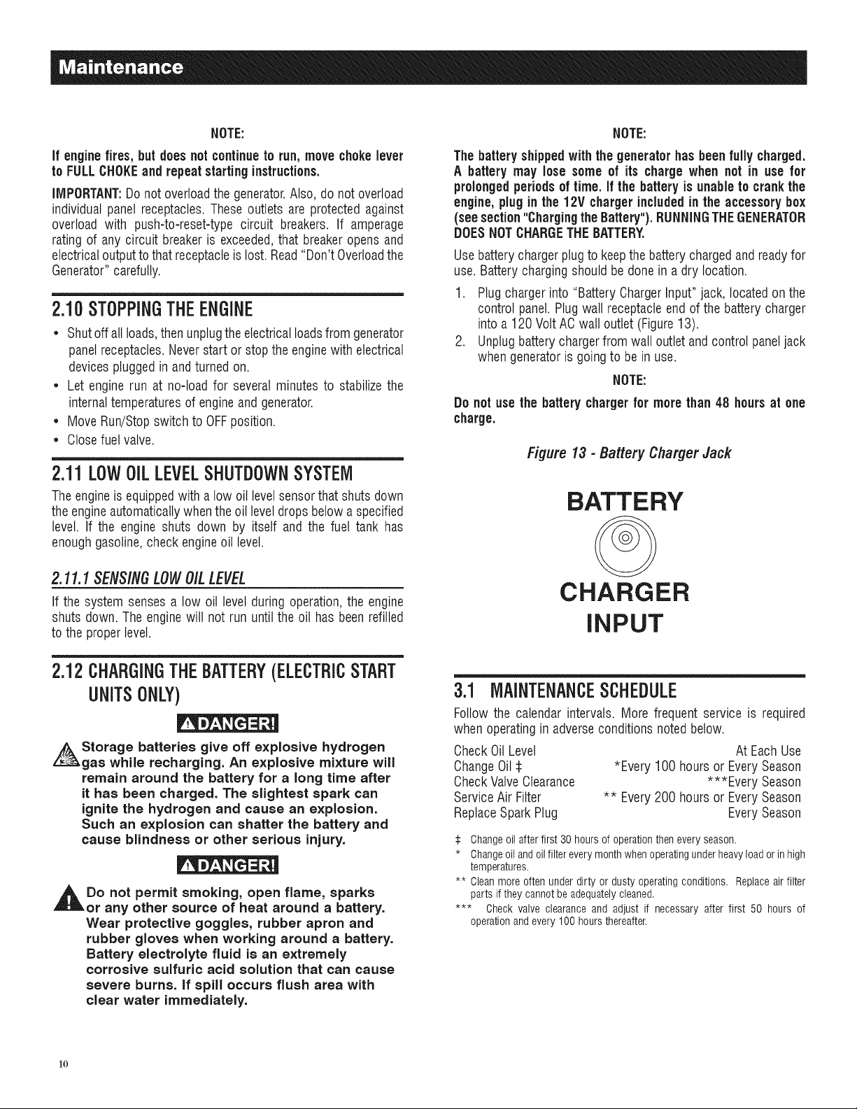
Figure 10 - Fuel Shut-off Valve
Figure 12 - Choke Position
CHOKELEVER
LEFT= CHOKE--
RIGHT= RUN
IMPORTANT:Donotoverloadthe generator.Also, donotoverload
individual panelreceptacles.These outlets are protectedagainst
overload with push-to-reset-typecircuit breakers. If amperage
ratingof any circuit breakeris exceeded,that breakeropens and
electricaloutputto that receptacleis lost.Read"Don't Overloadthe
Generator"carefully.
2.g STARTINGELECTRICSTARTENGINES
FUEL 3HUTOFF
Figure 11 - Engine ON/OFF Switch
ENGINE ON/OFF SWITCH
(PULL START ENGINES ONLY)
\
=11
z_Never start or stop engine with electrical
devices plugged into the receptacles AND
devices turned on.
• Unplug all electrical loads from the unit's receptaclesbefore
startingthe engine.
• Makesurethe unit is in a levelposition (notto exceed15° in
anydirection).
• Openthefuel shut-off valve (Figures10).
• Move engine CHOKEknob outward to FULLCHOKEposition
(Figure12).
• Tostart engine,pressandhold the Start/Run/Stopswitch inthe
"Start" position(Figure10). Theenginewill crankand attempt
to start. Whenthe enginestarts, releasethe switch to therun
position.
• When the engine starts, move choke knob to "1/2 Choke"
position until the engineruns smoothly and thenfully into the
"Run" position. If enginefalters, movechokeknob backoutto
"1/2 Choke" positionuntil the engine runs smoothlyand then
to "Run" position.
• This generatoris also equippedwith a manual recoil starter
which may beusedif the battery is discharged.
NOTE:
The switch must be in the RUN position. Use one of the
generator's receptacle outlets along with the includedbattery
chargerto chargethe battery whilethe generator is running.
• Tostart manually,firmly graspthe recoil handleand pullslowly
until increasedresistanceis felt. Pull rapidly up and away to
start engine.Thenfollow thesame chokesequence.
NOTE: NOTE:
if enginefires, but doesnot continueto run,movechokelever
to FULLCHOKEand repeatstartinginstructions.
IMPORTANT:Donotoverloadthe generator.Also, do not overload
individual panelreceptacles.These outlets are protectedagainst
overload with push-to-reset-type circuit breakers. If amperage
rating of any circuit breakeris exceeded,that breakeropensand
electricaloutputtothat receptacleis lost. Read"Don't Overloadthe
Generator"carefully.
2.10STOPPINGTHEENGINE
• Shutoff allloads,thenunplugthe electricalloadsfrom generator
panelreceptacles.Neverstart or stoptheenginewith electrical
devicespluggedin andturnedon.
• Let enginerun at no-load for several minutes to stabilizethe
internaltemperaturesof engineandgenerator.
• MoveRun/Stopswitch to OFFposition.
• Closefuelvalve.
2.11LOWOiLLEVELSHUTDOWNSYSTEM
Theengineis equippedwitha low oil levelsensorthat shutsdown
the engineautomaticallywhenthe oil leveldropsbelowa specified
level. If the engine shuts down by itself and the fuel tank has
enoughgasoline,checkengineoil level.
Thebattery shipped withthe generatorhasbeen fully charged.
A battery may lose some of its charge when not in use for
prolongedperiodsof time. If the battery is unableto crank the
engine, plugin the 12V chargerincludedin the accessory box
(seesection"Chargingthe Battery").RUNNINGTHEGENERATOR
DOESNOTCHARGETHEBATTERY.
Usebatterychargerplugto keepthebatterychargedandreadyfor
use. Batterychargingshouldbe done ina dry location.
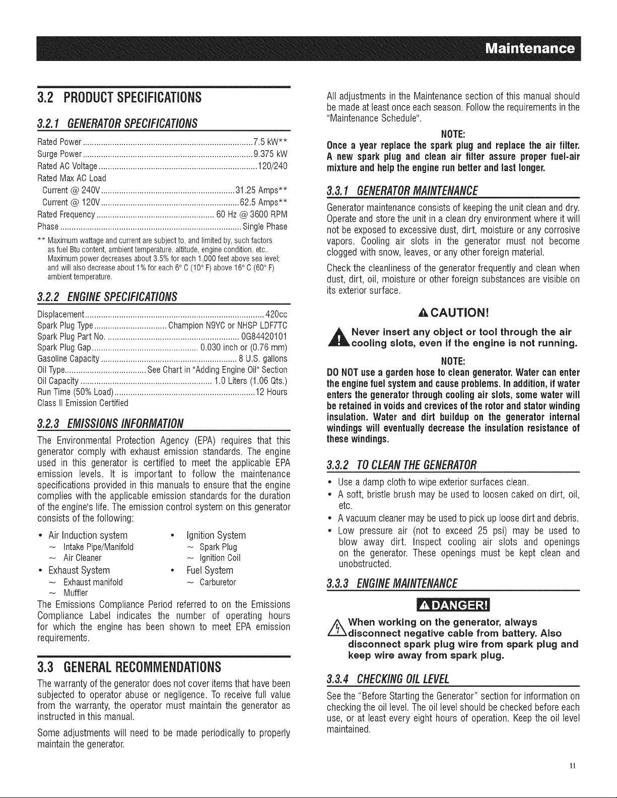
1. Plugchargerinto "BatteryChargerInput"jack, locatedon the
control panel.Plugwall receptacleendof the batterycharger
into a120 Volt AC wall outlet (Figure13).
2. Unplugbattery chargerfrom wall outlet andcontrol paneljack
whengeneratoris goingto be in use.
NOTE:
Do not use the battery chargerfor more than 48 hours at one
charge.
Figure 13 - Battery Charger Jack
BATTERY
2.11.1 SENSINGLOWOILLEVEL
If the system senses a low oil level during operation,the engine
shuts down.The enginewill not run until the oil has beenrefilled
to the properlevel.
2.12CHARGINGTHEBATTERY(ELECTRICSTART
UNITSONLY)
Storage batteries give off explosive hydrogen
gas while recharging. An explosive mixture will
remain around the battery for a long time after
it has been charged. The slightest spark can
ignite the hydrogen and cause an explosion.
Such an explosion can shatter the battery and
cause blindness or other serious injury.
,_Do not permit smoking, open flame, sparks
or any other source of heat around a battery.
Wear protective goggles, rubber apron and
rubber gloves when working around a battery.
Battery electrolyte fluid is an extremely
corrosive sulfuric acid solution that can cause
severe burns, if spill occurs flush area with
clear water immediately.
CHARGER
INPUT
3.1 MAINTENANCESCHEDULE
Follow the calendar intervals. More frequentservice is required
whenoperatingin adverseconditions noted below.
CheckOil Level
ChangeOil
CheckValveClearance
ServiceAir Filter
ReplaceSparkPlug
:i: Changeoil afterfirst 30 hours of operationthen every season.
* Changeoiland oilfilter every monthwhen operatingunderheavyload or in high
temperatures.
** Cleanmore often under dirty or dusty operatingconditions. Replaceair filter
parts ifthey cannot beadequatelycleaned.
*** Check valve clearance and adjust if necessary after first 50 hours of
operationand every100 hours thereafter.
*Every 100hoursor EverySeason
** Every200 hoursor EverySeason
At EachUse
***Every Season
EverySeason
1o
3.2 PRODUCTSPECiFiCATiONS
3.2.1 GENERATORSPEC/F/CAT/ONS
RatedPower........................................................................... 7.5 kW**
SurgePower........................................................................... 9.375 kW
RatedACVoltage...................................................................... 120/240
RatedMax ACLoad
Current@ 240V........................................................... 31.25 Amps**
Current@ 120V............................................................. 62.5 Amps**
RatedFrequency.................................................... 60 Hz@ 3600 RPM
Phase................................................................................ SinglePhase
** Maximumwattageandcurrentaresubjectto,andlimitedby,suchfactors
asfuelBtucontent,ambienttemperature,altitude,enginecondition,etc..
Maximumpowerdecreasesabout3.5%for each1,000feetabovesealevel;
andwillalsodecreaseabout1%for each6° C(10° F)above16°C(60° F)
ambienttemperature.
3.2.2 ENG/NESPECIFICATIONS
Displacement............................................................................... 420cc
SparkPlugType................................ ChampionN9YCor NHSPLDF7TC
SparkPlug PartNo........................................................... 0G84420101
SparkPlug Gap............................................... 0.030 inch or (0.76 mm)
GasolineCapacity............................................................ 8 U.S.gallons
OilType.................................... SeeChart in "AddingEngineOil"Section
OilCapacity.......................................................... 1.0Liters (1.06Qts.)
RunTime (50%Load)..............................................................12 Hours
ClassI1EmissionCertified
3.2.3 EMISS/ONS/NFORMATiON
The EnvironmentalProtection Agency (EPA) requires that this
generatorcomply with exhaustemission standards. The engine
used in this generator is certified to meet the applicable EPA
emission levels. It is important to follow the maintenance
specifications provided in this manualsto ensurethat the engine
complies withthe applicableemission standardsfor the duration
of theengine'slife. Theemissioncontrolsystem onthis generator
consists ofthe following:
* Air Induction system * Ignition System
IntakePipe/Manifold - SparkPlug
Air Cleaner _ IgnitionCoil
* Exhaust System * Fuel System
Exhaustmanifold _ Carburetor
Muffler
The EmissionsCompliancePeriod referred to on the Emissions
Compliance Label indicates the number of operating hours
for which the engine has been shown to meet EPA emission
requirements.
3.3 GENERALRECOMMENDATIONS
Thewarranty of the generatordoesnotcover items thathavebeen
subjectedto operatorabuse or negligence.To receive full value
from the warranty, the operatormust maintain the generatoras
instructed inthis manual.
Some adjustmentswill needto be made periodicallyto properly
maintainthegenerator.
All adjustments in the Maintenancesection of this manualshould
be madeatleastonceeachseason.Followthe requirementsin the
"MaintenanceSchedule".
NOTE:
Once a year replacethe sparkplug and replacethe air filter.
A new spark plugand clean air filter assure proper fuel-air
mixture andhelpthe enginerun better andlast longer.
3.3.1 GENERATORMA/NTENANCE
Generatormaintenanceconsists of keepingthe unit cleanand dry.
Operateandstorethe unitin a cleandry environmentwhereit will
not beexposedto excessivedust, dirt, moistureor any corrosive
vapors. Cooling air slots in the generator must not become
cloggedwith snow, leaves,or anyother foreign material.
Checkthe cleanlinessof the generatorfrequently andclean when
dust, dirt, oil, moisture or otherforeign substancesarevisible on
its exteriorsurface.
A.CAUTION!
_h Never insert any object or tool through the air
cooling slots, even if the engine is not running.
NOTE:
DONOTuse agarden hoseto cleangenerator.Water can enter
the enginefuel systemand causeproblems.In addition,if water
entersthe generatorthrough coolingair slots, some water will
be retainedinvoidsand crevicesof therotorand stator winding
insulation.Water and dirt buildup on the generator internal
windingswill eventually decrease the insulationresistanceof
these windings.
3.3.2 TOCLEANTHEGENERATOR
* Usea dampcloth to wipe exteriorsurfaces clean.
* A soft, bristlebrush may be used to loosencaked ondirt, oil,
etc.
* Avacuumcleanermay beusedto pick up loosedirt anddebris.
* Low pressure air (not to exceed 25 psi) may be used to
blow away dirt. Inspect cooling air slots and openings
on the generator.These openings must be kept clean and
unobstructed.
3.3.3 ENG/NEMAINTENANCE
//_When working on the generator, always
disconnect negative cable from battery. Also
disconnect spark plug wire from spark plug and
keep wire away from spark plug.
3.3.4 CHECK/NGOILLEVEL
Seethe "BeforeStartingthe Generator"sectionfor informationon
checkingthe oil level.Theoil levelshouldbe checkedbeforeeach
use, or at least everyeight hours of operation.Keepthe oil level
maintained.
11
3.3.5 CHANGINGTHEOIL
Changethe oil after the first 30 hours of operation.Changethe
oil every 100 hours or every seasonthereafter. If running this
unit underdirty or dusty conditions, or in extremelyhot weather,
changethe oil more often.
CAUTION!
,l_ Hot oil may cause burns. Allow engine to
cool before draining oil. Avoid prolonged
or repeated skin exposure with used oil.
Thoroughly wash exposed areas with soap.
Usethe following instructionsto changethe oil afterthe engine
coolsdown:
• Cleanareaaroundoil drain plug.
• Removeoil drain plugfrom engine andoil fill plug to drain oil
completelyintoa suitablecontainer.
• When oil has completely drained, install oil drain plug and
tighten securely.
• Filloil sumpwith recommendedoil. (See"Before Startingthe
Generator"for oil recommendations).
• Wipeup anyspilled oil.
• Disposeof usedoil at a propercollectioncenter.
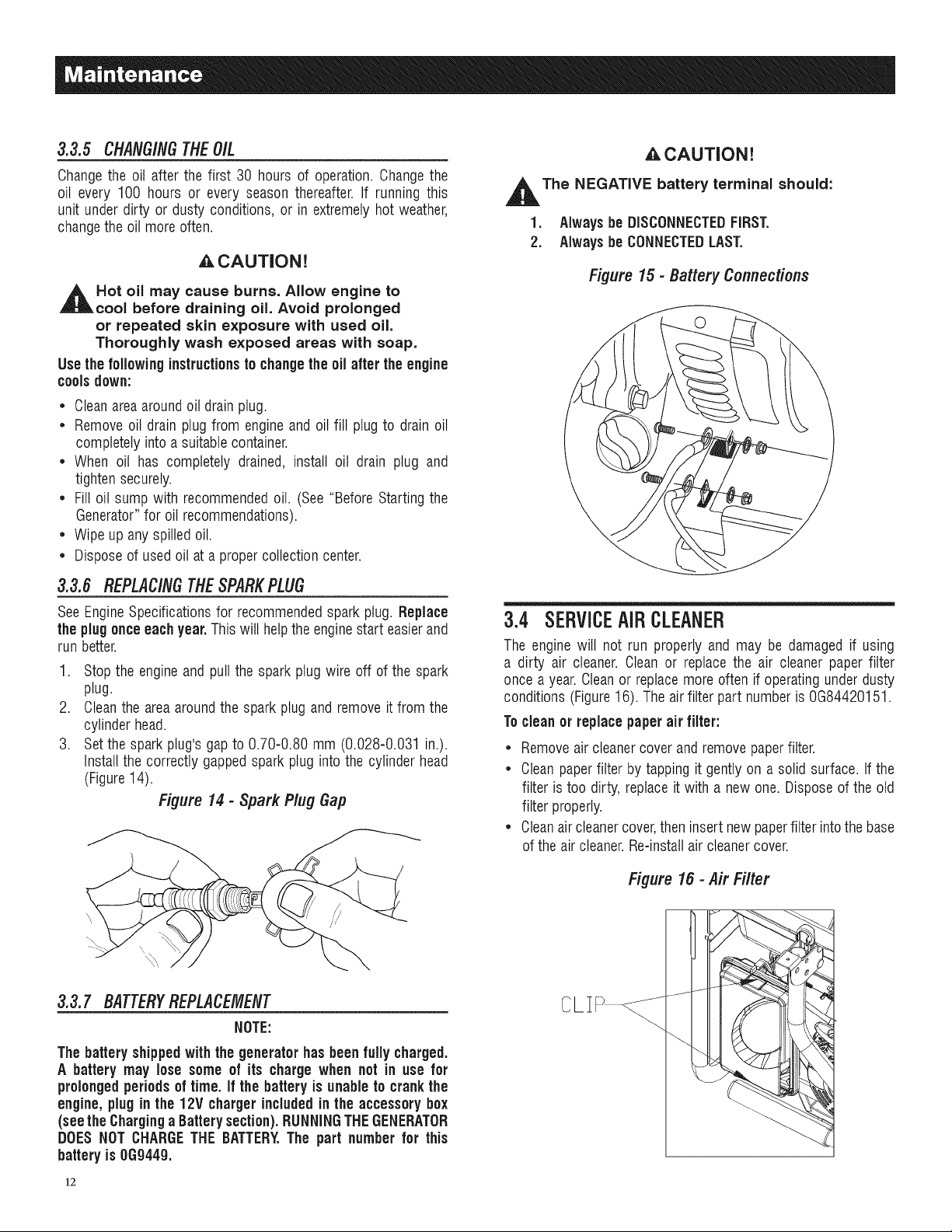
3.3.6 REPLACINGTHESPARKPLUG
_,CAUTION!
,_The NEGATIVE battery terminal should:
1. Always beDISCONNECTEDFIRST.
2. Alwaysbe CONNECTEDLAST.
Figure 15 - Battery Connections
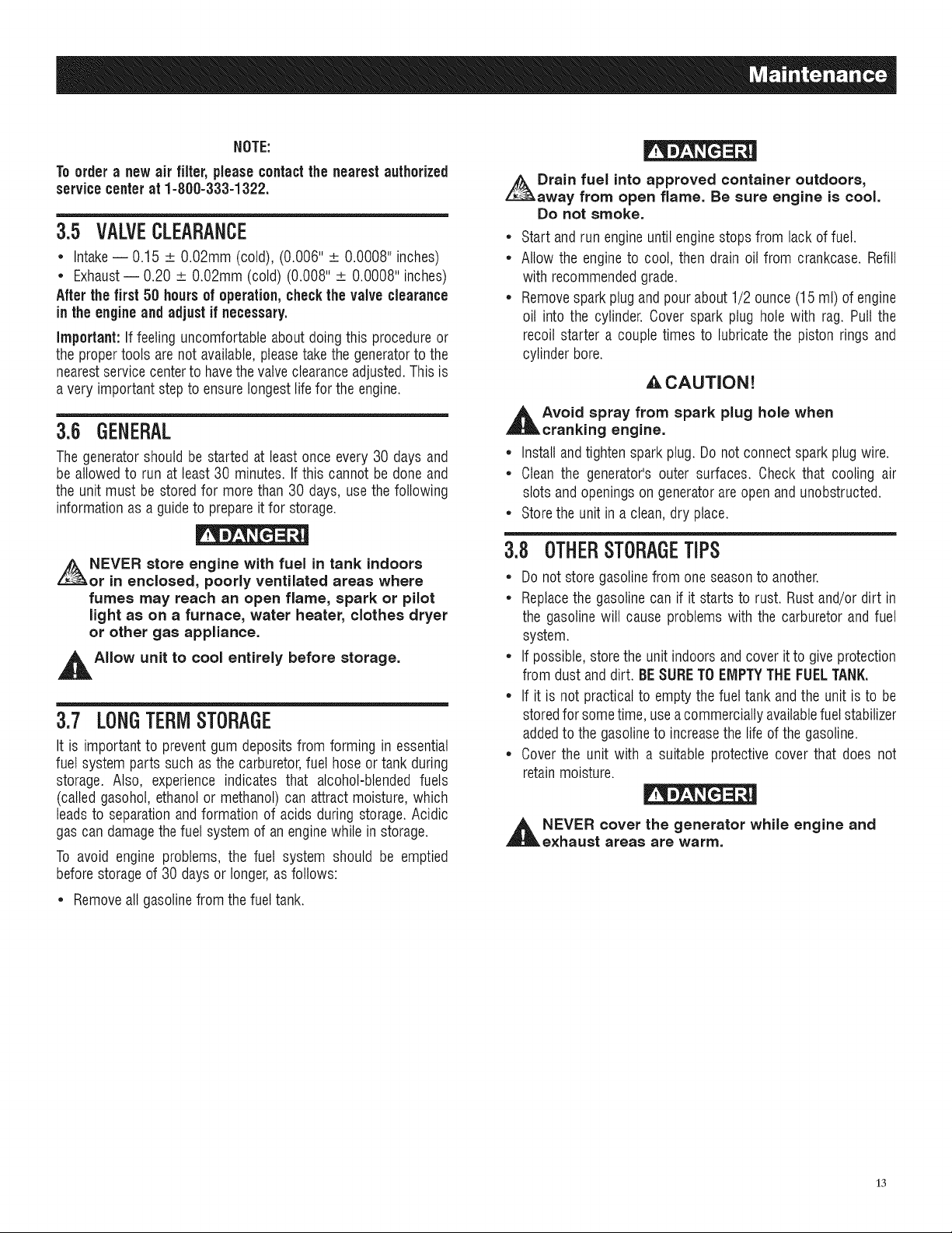
SeeEngineSpecificationsfor recommendedspark plug. Replace
the plugonce eachyear.This will helpthe enginestart easierand
run better.
1. Stopthe engineand pullthe spark plug wire off of the spark
plug.
2. Cleanthe areaaroundthe spark plug and removeit from the
cylinder head.
3. Setthe sparkplug'sgap to 0.70-0.80 mm (0.028-0.031 in.).
Installthe correctlygapped spark pluginto the cylinderhead
(Figure14).
Figure 14 - Spark Plug Gap
3.3.7 BATTERYREPLACEMENT
NOTE:
The battery shippedwiththe generator hasbeenfully charged.
A battery may lose some of its chargewhen net in use for
prolongedperiodsoftime. if the batteryis unableto crankthe
engine,plugin the 12V chargerincludedin the accessory box
(seetheCharging a Batterysection).RUNNINGTHEGENERATOR
DOESNOTCHARGETHE BATTERY.The part numberfor this
batteryis 069449.
12
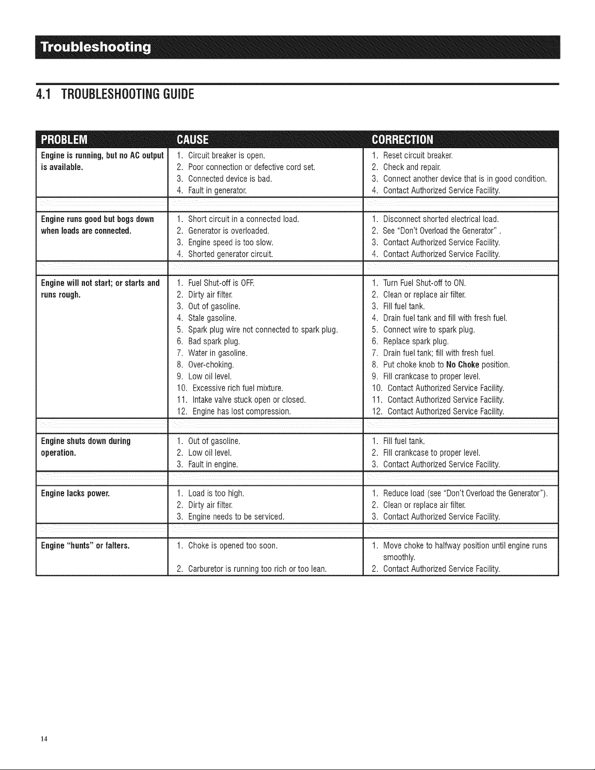
3.4 SERVICEAIRCLEANER
The enginewill not run properly and may be damagedif using
a dirty air cleaner.Cleanor replacethe air cleaner paper filter
oncea year.Cleanor replacemore oftenif operatingunderdusty
conditions(Figure16). Theair filter part numberis 0G84420151.
Toclean or replacepaperair filter:
• Removeair cleanercover andremove paperfilter.
• Cleanpaperfilter by tapping it gently on a solid surface. Ifthe
filter is too dirty, replaceit with a newone. Disposeof the old
filter properly.
• Cleanaircleanercover,theninsert newpaperfilter intothe base
ofthe aircleaner.Re-installair cleanercover.
Figure 15 - Air Filter
CLIf::::>
NOTE:
Toorder a new air filter, pleasecontactthe nearestauthorized
servicecenterat 1-800-333-1322.
3.5 VALVECLEARANCE
* Intake-- 0.15 _ 0.02mm (cold), (0.006" _ 0.0008" inches)
, Exhaust-- 0.20 _ 0.02mm (cold) (0.008" _ 0.0008" inches)
After the first 50 hours of operation, checkthe valve clearance
in the engine and adjust if necessary.
Important: If feelinguncomfortableaboutdoing this procedureor
theproper tools arenot available,pleasetakethe generatorto the
nearestservicecenterto havethevalveclearanceadjusted.Thisis
a very important stepto ensurelongestlife for theengine.
3.6 GENERAL
Thegeneratorshould be started at leastonce every 30 days and
be allowed to run at least 30 minutes.If this cannotbe done and
the unit must be storedfor more than 30 days, use thefollowing
informationas aguideto prepareitfor storage.
NEVER store engine with fuel in tank indoors
or in enclosed, poorly ventilated areas where
fumes may reach an open flame, spark or pilot
light as on a furnace, water heater, clothes dryer
or other gas appliance.
AIIow unit to cool entirely before storage.
3.7 LONGTERMSTORAGE
It is importantto preventgum depositsfrom forming in essential
fuel systemparts such asthe carburetor,fuel hoseor tank during
storage. Also, experience indicates that alcohol-blended fuels
(called gasohol,ethanol or methanol)can attractmoisture,which
leadsto separationandformation of acids duringstorage.Acidic
gascan damagethefuel systemof an enginewhile in storage.
To avoid engine problems, the fuel system should be emptied
beforestorageof 30 daysor longer,asfollows:
Drain fuel into approved container outdoors,
away from open flame. Be sure engine is cool.
Do not smoke.
• Startand runengineuntilenginestopsfrom lackof fuel.
• Allow the engineto cool, then drain oil from crankcase. Refill
with recommendedgrade.
• Removesparkplugandpour about 1/2 ounce(15 ml) of engine
oil into the cylinder. Cover spark plug hole with rag. Pull the
recoil starter a couple times to lubricatethe piston rings and
cylinder bore.
ACAUTION!
,_Avoid spray from spark plug hole when
cranking engine.
• Installandtighten spark plug.Donot connectspark plugwire.
• Cleanthe generator'souter surfaces. Check that cooling air
slots andopeningson generatorareopen andunobstructed.
• Storethe unit ina clean, dry place.
3.B OTHERSTORAGETiPS
* Do notstore gasolinefrom oneseasonto another.
, Replacethe gasolinecan if it starts to rust. Rustand/ordirt in
the gasolinewill cause problems with the carburetor andfuel
system.
, If possible,storethe unit indoorsandcover it to giveprotection
from dust anddirt. BESURETO EMPTYTHEFUELTANK.
* If it is not practicalto emptythe fuel tankand the unit is to be
storedfor sometime, useacommerciallyavailablefuelstabilizer
addedto the gasolineto increasethe lifeof thegasoline.
* Coverthe unit with a suitable protective cover that does not
retainmoisture.
,_ NEVER cover the generator while engine and
exhaust areas are warm,
• Removeall gasolinefrom the fueltank.
13
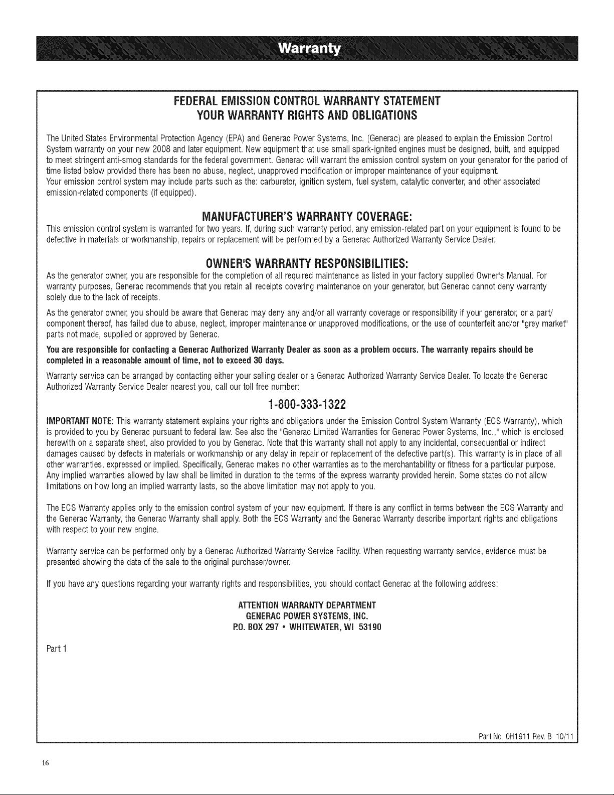
4.1 TROUBLESHOOTINGGUIDE
Engineis running,but noAC output
is available.
1. Circuit breakeris open.
2. Poorconnectionor defectivecord set.
3. Connecteddevice is bad.
4. Faultin generator.
= m ¸¸
1. Reset circuit breaker.
2. Check and repair.
3. Connect anotherdevicethat is in good condition.
4. Contact AuthorizedServiceFacility.
Engine runs good butbogs down 1. Short circuit in aconnectedload. 1. Disconnect shorted electricalload.
whenloads areconnected. 2. Generatoris overloaded. 2. See"Don't Overloadthe Generator".
3. Enginespeed is tooslow. 3. Contact AuthorizedService Facility.
4. Shorted generatorcircuit. 4. ContactAuthorizedServiceFacility.
Enginewill notstart; or startsand
runsrough.
FuelShut-off is OFR 1.
,
2.
Dirtyair filter. 2.
3.
Out of gasoline. 3.
4.
Stale gasoline. 4.
5.
Spark plugwire not connectedto sparkplug. 5.
6.
Badsparkplug. 6.
7. Water ingasoline.
8. Over-choking.
9. Low oil level.
10. Excessiverich fuel mixture.
11. Intakevalvestuck open or closed.
12. Enginehas lost compression.
. =
TurnFuelShut-offto ON.
Cleanor replaceair filter.
Fillfuel tank.
Drainfuel tank andfill with fresh fuel.
Connectwire to sparkplug.
Replacespark plug.
7. Drainfuel tank;fill withfresh fuel.
8. Put chokeknob to No Chokeposition.
9. Fill crankcaseto properlevel.
10. ContactAuthorizedService Facility.
11. ContactAuthorizedService Facility.
12. ContactAuthorizedService Facility.
Engineshuts down during 1. Out of gasoline. 1. Fillfuel tank.
operation. 2. Lowoil level. 2. Fill crankcaseto properlevel.
3. Faultin engine. 3. Contact AuthorizedServiceFacility.
Engine lacks power. 1. Loadis too high. 1. Reduceload (see"Don't Overloadthe Generator").
2. Dirty air filter. 2. Cleanor replaceair filter.
3. Engineneedsto beserviced. 3. Contact AuthorizedServiceFacility.
I |
Engine "hunts" or falters. 1. Chokeis openedtoo soon. 1. Move choke to halfway position untilengineruns
smoothly.
2. Carburetoris runningtoo rich or too lean. 2. ContactAuthorizedServiceFacility.
14

15
FEDERALEMiSSiONCONTROLWARRANTYSTATEMENT
YOURWARRANTYRIGHTSANDOBLiGATiONS
TheUnitedStates EnvironmentalProtectionAgency (EPA)and GeneracPowerSystems, Inc. (Generac)are pleasedto explainthe EmissionOontrol
Systemwarranty onyour new 2008and laterequipment.Newequipmentthat usesmall spark-ignitedenginesmust be designed,built, and equipped
to meetstringentanti-smog standardsfor the federalgovernment. Generacwill warrantthe emission control system onyour generatorfor the periodof
time listed below providedtherehas beenno abuse,neglect,unapprovedmodificationor improper maintenanceof your equipment.
Youremission control system may includeparts such asthe: carburetor,ignitionsystem,fuel system,catalytic converter,andother associated
emission-relatedcomponents (if equipped).
MANUFACTURER'SWARRANTYCOVERAGE:
This emission control system is warrantedfor two years. If, during such warranty period,any emission-relatedpart onyour equipmentis foundto be
defectivein materials or workmanship,repairs or replacementwill beperformed bya GeneracAuthorizedWarrantyServiceDealer.
OWNER'SWARRANTYRESPONSiBiLiTiES:
Asthe generatorowner,you areresponsiblefor the completion of all requiredmaintenanceas listedin your factory supplied Owner'sManual.For
warrantypurposes, Generacrecommendsthat you retainall receipts covering maintenanceon your generator,butGeneraccannot deny warranty
solelydueto thelack of receipts.
Asthe generatorowner,you shouldbe awarethat Generacmay denyany and/orall warranty coverageor responsibilityif your generator,or a part!
componentthereof, hasfailed dueto abuse,neglect, improper maintenanceor unapprovedmodifications,or the useof counterfeit and/or "grey market"
parts notmade, suppliedor approvedby Generac.
Youare responsible for contactinga GeneracAuthorizedWarrantyDealer as soon as a problemoccurs.The warrantyrepairsshould he
completed in a reasonable amount oftime, not to exceed30 days.
Warrantyservice canbe arrangedbycontactingeitheryour sellingdealer or a GeneracAuthorizedWarrantyService Dealer.Tolocatethe Generac
AuthorizedWarrantyService Dealernearestyou, call ourtoll free number:
1-800-333-1322
IMPORTANTNOTE:Thiswarranty statementexplainsyour rightsand obligations underthe EmissionOontrolSystemWarranty(EOSWarranty),which
is providedto youby Generacpursuanttofederal law. Seealso the "GeneracLimitedWarrantiesfor GeneracPowerSystems, Inc.,"which is enclosed
herewith on aseparatesheet, alsoprovidedto you by Generac.Notethatthis warrantyshall not applyto anyincidental,consequentialor indirect
damagescausedby defectsin materials or workmanshipor anydelayin repair or replacementof the defectivepart(s). This warranty is in placeof all
other warranties,expressedor implied. Specifically,Generacmakes no otherwarranties asto the merchantabilityor fitness for a particular purpose.
Any impliedwarrantiesallowedby law shall belimited in durationto theterms of the expresswarranty providedherein.Somestates do not allow
limitationson how longan impliedwarranty lasts, so theabovelimitation may not applyto you.
TheEOSWarrantyapplies only to theemission controlsystem of your new equipment.If thereis any conflict in termsbetweenthe ECSWarranty and
the GeneracWarranty,the GeneracWarrantyshall apply.Boththe EOSWarrantyand the GeneracWarrantydescribe importantrights and obligations
with respectto your new engine.
Warrantyservice canbe performed only by aGeneracAuthorizedWarrantyService Facility.Whenrequestingwarranty service,evidencemust be
presentedshowing the dateof thesaleto the original purchaser/owner.
If you haveany questionsregardingyour warranty rights andresponsibilities,you should contactGeneracatthe following address:
ATTENTIONWARRANTYDEPARTMENT
GENERACPOWERSYSTEMS,iNC.
P.O.BOX297 • WHITEWATER,Wl 53190
Part I
Part No. 0H1911 Rev.B 10/11
16
 Loading...