

Page 1
This is the safety alert symbol. It is used to alert you to potential personal injury hazards. Obey all safety
messages that follow this symbol to avoid possible injury or death.
Model No. 11400 (5000 Watt AC Generator) Manual No. B2267 Revision 2 (7/15/1999)
Visit our Generac website: www.generac-portables.com
Problems?
Questions?
Before taking your unit
back to the store,
call the generator
helpline at
1-800-270-1408
M-F 8-5 CT
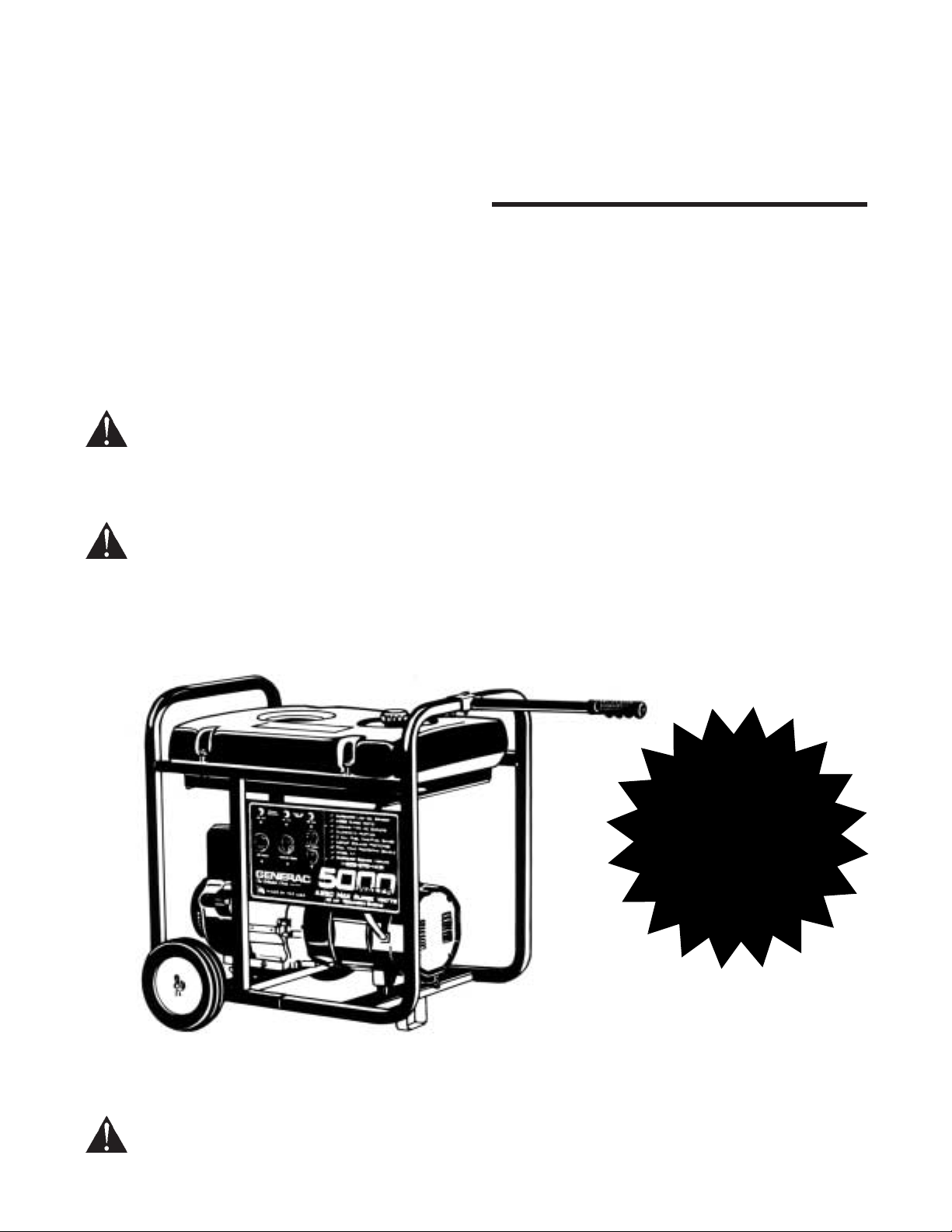
Portable Generator Owner’s Manual
DANGER! This generator is designed for outdoor use only. Never use this generator inside any building
or enclosure including the generator compartment of a recreational vehicle (RV). Carbon monoxide
poisoning, fire and/or an explosion may result. No user performed modifications, including venting of
exhaust and/or cooling ventilation, will eliminate the danger. Always have at least two feet of clearance on
all sides of the generator even while operating the unit outdoors.
DANGER! You must isolate the generator from the electric utility by opening the electrical systems main
circuit breaker or main switch if this unit is used for backup power. Failure to isolate the generator from
the power utility may result in injury or death to electric utility workers and damage to the
generator due to a backfeed of electrical energy.
The Emission Control System for this generator is warranted for standards set by the
Environmental Protection Agency. For warranty information refer to the Engine Owners manual.
PP5000T
GENERAC
The Reliable Ones
Page 2
Generac Portable Products PP5000T Generator
2
EQUIPMENT DESCRIPTION
The generator is an engine-driven, revolving field,
alternating current (AC) generator. It was designed to
supply electrical power for operating compatible
electrical lighting, appliance, tool and motor loads.
This manual contains information for a generator that
operates 120 and/or 240 Volt, single phase, 60 Hz
devices that require up to 5000 watts (5.0 kW) of
power that pull up to 41.7 Amps at 120 Volts or
20.8 Amps at 240 Volts
CAUTION! Do not exceed the generators
wattage/amperage capacity. See Dont
Overload the Generator on page 9.
The generators revolving field is driven at about
3600 rpm by a single-cylinder engine.
DANGER! Do not tamper with engine
governed speed. Improper operating speeds
are dangerous and increase risk of personal
injury or damage to equipment.
If you have any problems with the use of your
generator, please call the Generator Helpline at
1-800-270-1408.
Important: Any attempt to run the engine before it
has been serviced with the recommended oil will
result in an engine failure.
CONTENTS
Included with your generator are:
The main unit.
Wheel kit.
Video.
Engine Owners Manual.
Generator Owners Manual.
If unit is operated in cold weather, please review
Cold Weather Operation on page 7 before
discarding carton.
SAFETY RULES
This generator set was designed and manufactured
for specific applications. Do not attempt to modify the
unit or use it for any application it was not designed
for. If you have any questions about your generators
application, ask your dealer or consult the factory.
The manufacturer could not possibly anticipate every
circumstance that might involve a hazard. For that
reason, warnings in the manual and warnings on tags
or decals affixed to the unit are not all-inclusive. If you
intend to handle, operate or service the unit by a
procedure or method not specifically recommended
by the manufacturer, first make sure that such a
procedure or method will not render this equipment
unsafe or pose a threat to you and others.
Read this manual carefully and become familiar
with your generator set. Know its applications, its
limitations and any hazards involved.
The generator produces a very powerful voltage
that can cause extremely dangerous electrical
shock. Avoid contact with bare wires, terminals, etc.
Never permit an untrained person to operate or
service the generator.
Never handle any kind of electrical cord or device
while standing in water, while barefoot, or while
hands or feet are wet.
The National Electric Code requires the frame and
external electrically conductive parts of the
generator be properly connected to an approved
earth ground. Local electrical codes may also
require proper grounding of the generator. Consult
with a local electrician for grounding requirements
in your area.
Use a ground fault circuit interrupter in any damp or
highly conductive area (such as metal decking or
steel work).
The engine exhaust from this product contains
chemicals known to the State of California to
cause cancer, birth defects, or other
reproductive harm.
WWAARRNNIINNGG::
Page 3
Generac Portable Products PP5000T Generator
3
Do not use worn, bare, frayed or otherwise
damaged electrical cord sets with the generator.
Using a defective cord set may result in electrical
shock or damage to equipment and/or property.
Operate unit only on level surfaces and where it will
not be exposed to excessive moisture, dirt, dust or
corrosive vapors.
Gasoline is highly FLAMMABLE and its vapors are
EXPLOSIVE. Do not permit smoking, open flames,
sparks or heat in the vicinity while handling
gasoline. Avoid spilling gasoline on a hot engine.
Comply with all laws regulating storage and
handling of gasoline.
Do not overfill the fuel tank. Always allow room for
fuel expansion. If tank is overfilled, fuel can overflow
onto a hot engine and cause FIRE or EXPLOSION.
Never store a generator with fuel in the tank where
gasoline vapors might reach an open flame, spark
or pilot light (as on a furnace, water heater, clothes
dryer). FIRE or EXPLOSION may result.
Generator exhaust gases contain DEADLY carbon
monoxide gas. This dangerous gas, if breathed in
sufficient concentrations, can cause
unconsciousness or even death. Operate this
equipment only in the open air where adequate
ventilation is available.
The engine-generator requires an adequate flow of
cooling air for its continued proper operation. Never
operate the unit inside any room or enclosure
where the free flow of cooling air into and out of the
unit might be obstructed. Without sufficient cooling
air flow, the unit quickly overheats, damaging the
generator or nearby property.
Allow at least 2 feet of clearance on all sides of
generator, even while operating unit outdoors, or
you could damage the unit. However, when
operating unit in cold weather, refer to the Cold
Weather Operation section on page 7.
Never start or stop the engine-generator with
electrical loads connected to receptacles AND with
the connected devices turned ON. Start the engine
and let it stabilize before connecting any electrical
loads. Disconnect all electrical loads before shutting
down the generator.
Do not insert any object through cooling slots of the
engine-generator. You could damage the unit or
injure yourself.
Never operate the generator: in the rain; in any
enclosed compartment; if connected electrical
devices overheat; if electrical output is lost; if
engine or generator sparks; if flame/smoke is seen
while unit is running; if unit vibrates excessively.
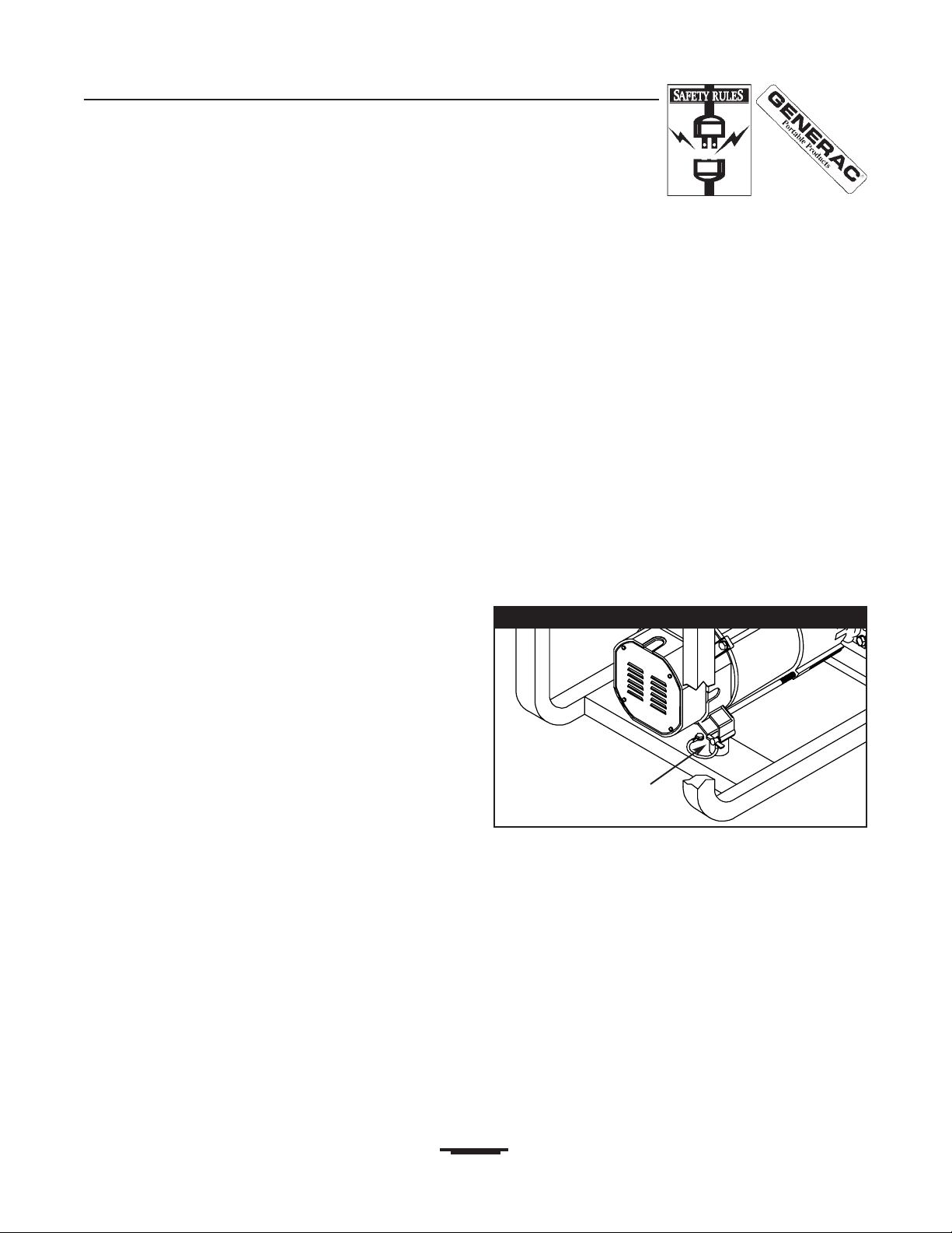
GROUNDING THE
GENERATOR
The National Electrical Code requires that the frame
and external electrically conductive parts of this
generator be properly connected to an approved
earth ground. Local electrical codes may also require
proper grounding of the unit. For that purpose, a
GROUNDING WING NUT is provided on the
generator (Figure 1).
Generally, connecting a No. 12 AWG (American Wire
Gauge) stranded copper wire to the grounding wing
nut and to an earth-driven copper or brass grounding
rod (electrode) provides adequate protection against
electrical shock. Be careful to keep the grounding
wire attached after connecting the stranded copper
wire. However, local codes may vary widely. Consult
with a local electrician for grounding requirements in
your area.
Properly grounding the generator helps prevent
electrical shock if a ground fault condition exists in the
generator or in connected electrical devices. Proper
grounding also helps dissipate static electricity, which
often builds up in ungrounded devices.
Figure 1 Grounding Wing Nut
Grounding Wing Nut
Page 4
Generac Portable Products PP5000T Generator
4
120 Volt AC, 20 Amp Receptacles May be used
to supply electrical power for the operation of 120 Volt
AC, 20 Amp, single phase, 60 Hz electrical lighting,
appliance, tool and motor loads.
120 Volt AC, 30 Amp Locking Receptacle May
be used to supply electrical power for the operation of
120 Volt AC, 30 Amp, single phase, 60 Hz electrical
lighting, appliance, tool and motor loads.
120/240 Volt AC, 20 Amp Locking Receptacle
May be used to supply electrical power for the
operation of 120 and/or 240 Volt AC, 20 Amp, single
phase, 60 Hz AC electrical lighting, appliance, tool
and motor loads.
Air Filter This engine assembly filters air entering
the engine.
Circuit Breakers (AC) Each receptacle is
provided with a circuit breaker to protect the
generator against electrical overload. Breakers are
"push to reset" type.
Fuel Shut Off Valve Controls fuel supply to
engine.
Fuel Tank Capacity of 4 U.S. gallons.
Grounding Wing Nut Provides a tie-point for
connecting the generator frame to earth ground.
Run/Stop Switch Must be in Run position to start
engine. Set to Stop to stop a running engine.
SPECIFICATIONS
Rated Maximum Continuous
Wattage Capacity 5000 Watts
Power Factor 1.0
Rated Maximum Continuous Load Current
At 120 Volts 41.67 Amps
At 240 Volts 20.83 Amps
Phase 1-phase
Rated Frequency 60 Hertz
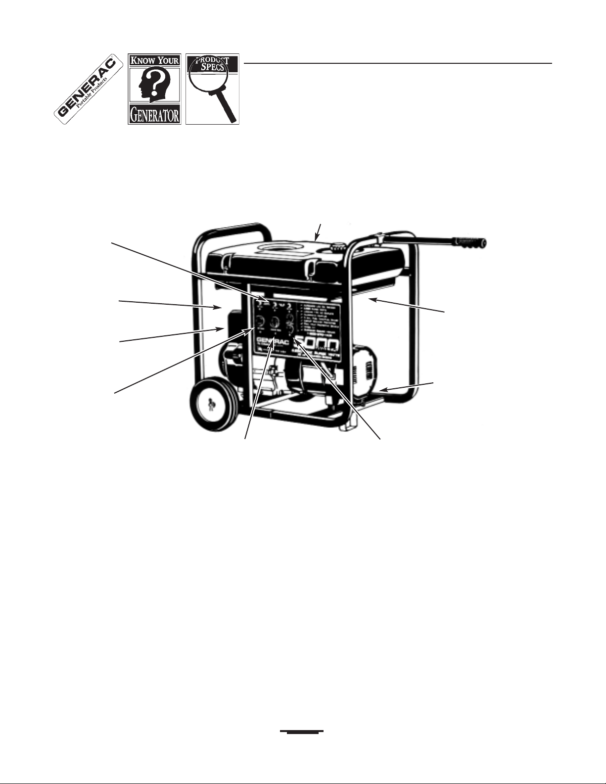
KNOW YOUR GENERATOR
Read this owners manual and safety rules before operating your generator.
Compare the illustrations with your generator to familiarize yourself with the locations of various controls and
adjustments. Save this manual for future reference.
Circuit Breakers (AC)
Fuel Tank
120 Volt AC, 30 Amp
Locking Receptacle
Run/Stop Switch
Air Filter
120/240 Volt AC, 20 Amp
Locking Receptacle
120 Volt AC, 20 Amp
Receptacles
Grounding Wing Nut
Fuel ShutOff Valve
Page 5
Generac Portable Products PP5000T Generator
5
WHEEL KIT INSTALLATION
To install wheel kit you need the following tools:
15/16" (22mm) box, open end, or socket wrench
Two 13mm box, open end, or socket wrenches
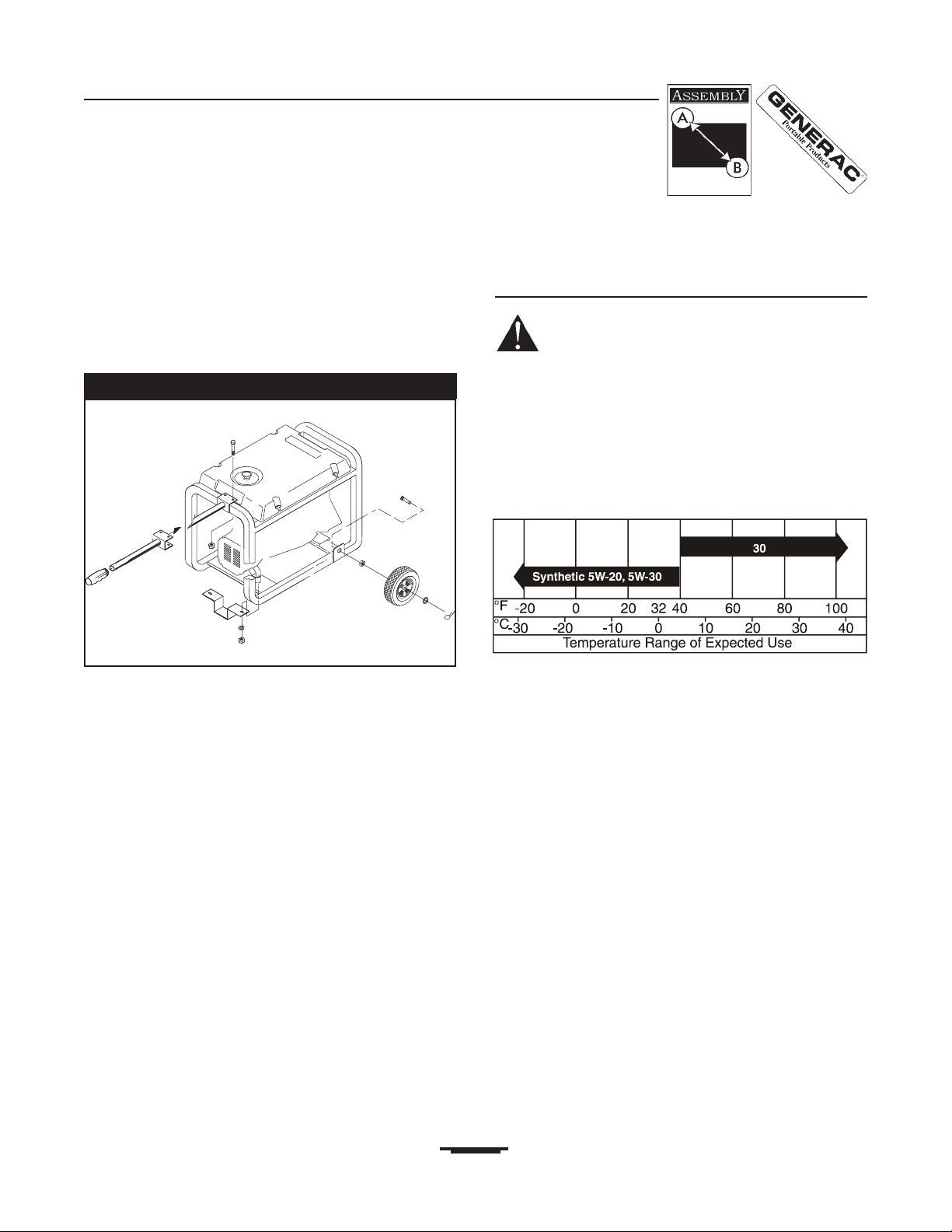
Install Wheel Kit as follows: (Refer to Figure 2)
Place bottom of generator cradle on a flat surface.
Place axle stud through wheel retainer on cradle
frame.
Use 15/16 wrench to secure the axle stud to frame
with 5/8-18 jam nut.
Install the other axle stud in the same manner.
NOTE: Be sure to install wheel with raised hub
inboard.
Place flat washer over axle stud, tip unit and install
the wheel.
Retain wheel on axle stud with retaining pin. Install
other wheel on remaining axle shaft the same way.
Remove two front nuts and lock washers from
vibration mount with 13mm wrench. Use these nuts
to retain the mounting leg.
Center the lifting handle on generator end of cradle.
Attach the handle using two 13mm wrenches with
two capscrews and two hex nuts.
BEFORE STARTING UNIT
Add Oil
WARNING! Any attempt to start the engine
before it has been properly filled with the
recommended oil may result in engine failure.
NOTE: When adding oil to the engine crankcase in
the future, use only clean, high quality detergent oil
rated with API service classification SF, SG, SH,
SH/CD or higher rated SAE 30. Use no special
additives.
Select the oil's viscosity grade according to your
expected operating temperature:
Summer - Above 40°F, use SAE 30.
Winter - Below 40°F, use synthetic SAE 5W30 or
SAE 10W.
DO NOT USE SAE 10W40
Although multi-viscosity oils (5W30, 10W30, etc.)
improve starting in cold weather, these multi-viscosity
oils will result in increased oil consumption when used
above 32°F. Check your engine oil level more
frequently to avoid possible damage from running low
on oil. Review oil fill instructions in the engine manual.
To fill your engine with oil:
Place generator on a level surface.
Clean area around oil fill and remove oil fill plug and
dipstick.
Wipe dipstick clean.
Pour oil into oil fill opening until oil reaches FULL
mark on the dipstick. Do not overfill!
NOTE: The generators revolving field rides on a pre-
lubricated and sealed ball bearing that requires no
additional lubrication for the life of the bearing.
Figure 2 Installing the Wheel Kit
Capscrew
Handle
Grip
Nut
Mounting Leg
Use Existing
Fasteners to
Secure Leg
Jam Nut
Retaining Pin
Wheel
Washer
Axle Stud
Page 6

Generac Portable Products PP5000T Generator
6
Add Gasoline
DANGER! NEVER fill fuel tank indoors.
NEVER fill fuel tank when engine is running or
hot. DO NOT light a cigarette or smoke when
filling the fuel tank.
WARNING! Do not overfill the fuel tank.
Always allow room for fuel expansion.
Use regular UNLEADED gasoline with the
generator engine. Do not use gasoline containing
methanol. Do not mix oil with gasoline.
Clean area around fuel fill cap, remove cap.
Slowly add unleaded regular gasoline to fuel tank.
Be careful not to overfill. Allow about 1/2" of tank
space for fuel expansion, as shown in Figure 3.
Install fuel cap and wipe up any spilled gasoline.
IMPORTANT: It is important to prevent gum deposits
from forming in essential fuel system parts such as
the carburetor, fuel filter, fuel hose or tank during
storage. Also, experience indicates that alcoholblended fuels (called gasohol or ethanol) can attract
moisture, which leads to separation and formation of
acids during storage. Acidic gas can damage the fuel
system of an engine while in storage.
To avoid engine problems, the fuel system should be
emptied before storage of 30 days or longer. See
Storage on page 10. Never use engine or carburetor
cleaner products in the fuel tank or permanent
damage may occur.
OPERATING THE
GENERATOR
CAUTION! Never start or stop the engine
with electrical loads connected generator AND
with the connected devices turned ON.
Starting the Engine
DANGER! Breathing Hazard! Never run
engine indoors or in enclosed poorly ventilated
areas. Engine exhaust contains carbon
monoxide, an odorless and deadly gas.
WARNING! Burn Hazard! Temperature of
muffler and nearby areas may exceed 150°F
(65°C). Avoid these areas.
Unplug all electrical loads from generator
receptacles before starting the engine.
Make sure the unit is in a level position.
Open the fuel shutoff valve (Figure 4).
Move the choke lever to the Full Choke position
(Figure 5).
Figure 5 Choke Positions
Full Choke Position
No Choke
Position
Figure 4 Open Fuel Tank Valve
Figure 3 Recommended Air Space
Page 7

Generac Portable Products PP5000T Generator
7
Set the engine Run/Stop switch to the On ()
position.
Grasp starter grip and pull slowly until you feel
some resistance. Then pull cord out with rapid full
arm stroke. Let rope return slowly. Do not let rope
snap back against starter.
When engine starts, move choke lever to a
Half Choke position until the engine runs
smoothly and then to No Choke position. If engine
falters, move choke lever to Half Choke position
until the engine runs smoothly and then to
No Choke position.
NOTE: If engine fails to start after 3 pulls, move the
choke lever to No Choke position and pull starter
rope again.
NOTE: If the engine fails to start after three (3) pulls,
check for proper oil level in crankcase. Unit is
equipped with a low oil shutdown system. Refer to
engine owners manual for further information.
NOTE: If engine fires, but does not continue to run,
move choke lever to Full Choke and repeat starting
instructions.
Connecting Electrical Loads
Let engine stabilize and warm up for a few minutes
after starting.
Plug in and turn on the desired 120 and/or 240 Volt
AC, single phase, 60 Hz electrical loads.
Do not connect 240 Volt loads to the 120 Volt
receptacles.
Do not connect 3phase loads to the generator.
Do not connect 50 Hz loads to the generator.
DO NOT OVERLOAD THE GENERATOR. Add up
the rated watts (or amps) of all loads to be
connected at one time. This total should not be
greater than the rated wattage/amperage capacity
of the generator. See Dont Overload the
Generator on page 9.
Stopping the Engine
Unplug all electrical loads from generator panel
receptacles. Never start or stop engine with
electrical devices plugged in and turned on.
Let engine run at no-load for several minutes to
stabilize the internal temperatures of engine and
generator.
Move engine control switch to Off (o) position.
Close the fuel shutoff valve.
COLD WEATHER
OPERATION
Under certain weather conditions (temperatures
below 40°F [4°C] and a high dew point), your
Generac generator may experience icing of the
carburetor and/or the crankcase breather system.
In an emergency, use the original shipping box as a
temporary shelter:
Cut off all flaps
Cut out one of the long sides of the box to expose
exhaust side of unit. Ensure a minimum of two feet
clearance between open side of box and nearest
object.
Cut appropriate slots to access receptacles of unit.
You may also need to cut a clearance slot for the
handle.
Start unit, then place box over it.
IMPORTANT!: Remove shelter when temperature is
above 40°F [4°C].
For a more permanent shelter, build a structure that
will enclose three sides and the top of the generator:
Make sure entire muffler-side of generator is
exposed. A typical generator is shown in Figure 6.
Figure 6 Temporary Shelter (handle/wheels omitted)
Page 8

Generac Portable Products PP5000T Generator
8
Ensure a minimum of two feet clearance between
open side of box and nearest object.
Face exposed end away from wind and elements.
Enclosure should hold enough heat created by the
generator to prevent icing problems.
CAUTION: NEVER run unit indoors; Do not
enclose generator any more than shown.
Remove shelter when temperatures are above
40°F [4°C].
RECEPTACLES
120 Volt, 20 Amp Duplex Receptacle
Each of these receptacles is protected against
overload by a 20 Amp push-to-reset type circuit
breakers. Use each receptacle to operate 120 Volt
AC, 20 Amp, 60 Hz, single phase loads (Figure 7).
120/240 Volt, 20 Amp Locking
Receptacle
Use a NEMA L14-20P type plug with this receptacle.
Connect a 4-wire cord set rated for 250 Volts at
20 Amps (or greater) (Figure 8).
You can use the same 4-wire cord if you plan only to
run a 120 Volt load. This receptacle powers 120 or
240 Volt AC, 60 Hz, single phase loads and is
protected by a 20 Amp push-to-reset circuit breaker.
120 Volt, 30 Amp Locking
Receptacle
Use a NEMA L5-30P type plug with this receptacle.
Connect a 3-wire cord set rated for 125 Volts at
30 Amps to the plug (Figure 9).
Use this receptacle to operate 120 Volt AC, 60 Hz,
single phase loads requiring up to 3600 watts
(3.6 kW) of power at 30 Amps. The outlet is protected
by a 30 Amp push-to-reset circuit breaker.
Figure 9 120 Volt, 30 Amp Locking Receptacle
Figure 8 120/240 Volt, 20 Amp Locking Receptacle
Figure 7 120 Volt, 20 Amp Receptacle
Page 9

Generac Portable Products PP5000T Generator
9
DONT OVERLOAD THE
GENERATOR
Overloading a generator in excess of its rated wattage
capacity can result in damage to the generator and/or
connected electrical devices. Observe the following,
to prevent overloading the unit:
Add up the total wattage of all electrical devices to
be connected at one time. This total should NOT be
greater than the generators wattage capacity.
The rated wattage of lights can be taken from light
bulbs. The rated wattage of tools, appliances and
motors can usually be found on a data plate or
decal affixed to the device.
If the appliance, tool or motor does not give
wattage, multiply 120 Volts times ampere rating to
determine watts (volts x amps = watts).
Some electric motors, such as induction types,
require about three times more watts of power for
starting than for running. This surge of power lasts
for only a few seconds when starting such motors.
Be sure you allow for this high starting wattage
when selecting electrical devices to connect to your
generator. First figure the watts needed to start the
largest motor. Add to that figure the running watts of
all other connected loads.
Items in the wattage reference guide (Figure 10)
are provided to help you to determine how many
items the generator can operate at one time.
RUNNING WATTS
*Air Conditioner (12,000 Btu)......................................1700
Battery Charger (20 amp).............................................500
Belt Sander (3) ..........................................................1000
Chain Saw ..................................................................1200
Circular Saw (6-1/2) .......................................800 to 1000
Coffee Maker..............................................................1000
*Compressor (1 HP) ...................................................2000
*Compressor (3/4 HP) ................................................1800
*Compressor (1/2 HP) ................................................1400
Curling Iron...................................................................700
*Freezer........................................................................500
Disc Sander (9) .........................................................1200
Edge Trimmer...............................................................500
Electric Nail Gun.........................................................1200
Electric Range (one element).....................................1500
Electric Skillet .............................................................1250
*Furnace Fan (1/3 HP) ...............................................1200
Hair Dryer ...................................................................1200
Hand Drill (1) .............................................................1100
Hand Drill (1/2) ...............................................750 to 1000
Hand Drill (3/8) ............................................................500
Hand Drill (1/4) ............................................................250
Hedge Trimmer.............................................................450
RUNNING WATTS
Impact Wrench .............................................................500
*Jet Pump.....................................................................800
Lawn Mower ...............................................................1200
Light Bulb......................................................................100
Microwave Oven...........................................................700
*Milk Cooler ................................................................1100
Oil Burner on Furnace ..................................................300
Oil Fired Space Heater (140,000 Btu) ..........................400
Oil Fired Space Heater (85,000 Btu) ............................225
Oil Fired Space Heater (30,000 Btu) ............................150
*Paint Sprayer, Airless (1/3 HP) ...................................600
Paint Sprayer, Airless (handheld) .................................150
Radio ...................................................................50 to 200
*Refrigerator .................................................................600
Slow Cooker .................................................................200
*Submersible Pump (1-1/2 HP) ..................................2800
*Submersible Pump (1 HP) ........................................2000
*Submersible Pump (1/2 HP) .....................................1500
Sump Pump................................................................. 600
*Table Saw (10) ............................................1750 to 2000
Television...........................................................200 to 500
Weed Trimmer..............................................................500
* Allow 3 times the listed watts for starting these devices.
Figure 10 Wattage Reference Guide
Page 10

Generac Portable Products PP5000T Generator
10
GENERAL MAINTENANCE
RECOMMENDATIONS
The Owner/Operator is responsible for making sure
that all periodic maintenance tasks are completed on
a timely basis; that all discrepancies are corrected;
and that the unit is kept clean and properly stored.
Never operate a damaged or defective generator.
Engine Maintenance
See Engine Owners Manual for instructions.
Generator Maintenance
Generator maintenance consists of keeping the unit
clean and dry. Operate and store the unit in a clean
dry environment where it will not be exposed to
excessive dust, dirt, moisture or any corrosive vapors.
Cooling air slots in the generator must not become
clogged with snow, leaves or any other foreign
material.
NOTE: We do not recommend using a garden hose to
clean generator. Water can enter engine fuel system
and cause problems. In addition, if water enters
generator through cooling air slots, some of the water
will be retained in voids and cracks of the rotor and
stator winding insulation. Water and dirt buildup on
the generator internal windings will eventually
decrease the insulation resistance of these windings.
To Clean the Generator
Use a damp cloth to wipe exterior surfaces clean.
Soft, bristle brush may be used to loosen caked on
dirt or oil.
A vacuum cleaner may be used to pick up loose dirt
and debris.
Low pressure air (not to exceed 25 psi) may be
used to blow away dirt. Inspect cooling air slots and
opening on generator. These openings must be
kept clean and unobstructed.
STORAGE INSTRUCTIONS
The generator should be started at least once
every seven days and allowed to run at least
30 minutes. If this cannot be done and you must
store the unit for more than 30 days, use the following
information as a guide to prepare it for storage.
Generator Storage
Clean the generator as outlined earlier in To Clean
the Generator.
Check that cooling air slots and openings on
generator are open and unobstructed.
DANGER! Storage covers can be flammable.
Do not place a storage cover over a hot
generator. Let the unit cool for a sufficient time
before placing the cover on the unit.
Engine Storage
See Engine Owners Manual for instructions.
Other Storage Tips
Do not store gasoline from one season to another.
Replace your gasoline can if it starts to rust. Rust
and/or dirt in a gasoline can cause problems when
you use that fuel with this unit.
Store in clean and dry area.
Page 11

Generac Portable Products PP5000T Generator
11
TROUBLESHOOTING
Problem
Engine is running, but no AC
output is available.
Engine runs good but bogs
down when loads are
connected.
Engine will not start; or starts
and runs rough.
Engine shuts down during
operation.
Engine lacks power.
Engine hunts or falters.
Cause
1. Circuit breaker is open.
2. Poor connection or defective cord
set.
3. Connected device is bad.
4. Fault in generator.
1. Short circuit in a connected load.
2. Generator is overloaded.
3. Engine speed is too slow.
4. Shorted generator circuit.
1. On/Off switch set to Off (o).
2. Dirty air cleaner.
3. Out of gasoline.
4. Stale gasoline.
5. Spark plug wire not connected to
spark plug.
6. Bad spark plug.
7. Water in gasoline.
8. Overchoking.
9. Low oil level.
10. Excessively rich fuel mixture.
11. Intake valve stuck open or closed.
12. Engine has lost compression.
1. Out of gasoline.
2. Low oil level.
3. Fault in engine.
1. Load is too high.
2. Dirty air filter.
3. Engine needs to be serviced.
1. Choke is opened too soon.
2. Carburetor is running too rich or
too lean.
Solution
1. Reset circuit breaker.
2. Check and repair.
3. Connect another device that is in
good condition.
4. Contact Generac service facility.
1. Disconnect shorted electrical load.
2. See Dont Overload the Generator
on page 9.
3. Contact Tecumseh service facility.
4. Contact Generac service facility.
1. Set switch to On ().
2. Clean or replace air cleaner.
3. Fill fuel tank.
4. Drain gas tank and fill with fresh
fuel.
5. Connect wire to spark plug.
6. Replace spark plug.
7. Drain gas tank; fill with fresh fuel.
8. Put choke lever to no choke
position.
9. Fill crankcase to proper level.
10. Contact Tecumseh service facility.
11. Contact Tecumseh service facility.
12. Contact Tecumseh service facility.
1. Fill fuel tank.
2. Fill crankcase to proper level.
3. Contact Tecumseh service facility.
1. See Dont Overload the Generator
on page 9.
2. Replace air filter.
3. Contact Tecumseh service facility.
1. Move choke to halfway position till
engine runs smoothly.
2. Contact Tecumseh service facility.
Page 12

Generac Portable Products PP5000T Generator
12
SCHEMATIC & WIRING DIAGRAM
Page 13

Generac Portable Products PP5000T Generator
13
WHEEL KIT EXPLODED VIEW & PARTS LIST
Item Part # Qty Description
1 87005A 2 PIN, Retaining
2 87280 2 WHEEL, 8" Dia.
3 93728 2 STUD, Axle
4 94222Q 2 NUT, 5/8" - 18 Jam
5 49808 2 WASHER, Flat
Item Part # Qty Description
6 94034 1 LEG, Mounting
8 84910 1 HANDLE, Lifting
9 75928 1 GRIP, Handle
10 39287 2 CAP SCREW, M8-1.25 x 45
11 52858 2 NUT, M8-1.25 Hex Lock
10
8
3
5
4
2
1
9
6
Use Existing Fasteners
to Secure #6
11
Page 14

Generac Portable Products PP5000T Generator
14
UNIT EXPLODED VIEW
Page 15

Generac Portable Products PP5000T Generator
15
UNIT EXPLODED VIEW
Item Part # Qty Description
1 NSP 1 ENGINE, Tecumseh 10HP
2 66825B 1 CARRIER, Rear Bearing
3 91825 1 ASSEMBLY, Brush & Bridge
Rectifier
4 66365D 1 ADAPTER, Housing
5 22129 2 LOCK WASHER, M8
6 86307 4 SCREW, Hex Hd 5/16-24 x 3/4
Sems
7 74716J 1 ASSEMBLY, Rotor
8 65791 1 BEARING
9 96796 1 WASHER, Special
10 75431 1 BOLT, Rotor
11 91859J 1 ASSEMBLY, Stator
12 81917 1 PIN, Roll M4 x 10 Lg.
13 86308C 4 BOLT, Stator
14 22769 1 WASHER, Shakeproof Int #10
15 22145 2 WASHER, Flat 5/16, M8
16 70642 2 MOUNT, Vibration - 45°
17 67025 1 COVER, Bearing Carrier
18 52858 6 LOCK NUT, M8-1.25 Flange
19 76222 2 PPHMS, M8-1.25 x 40 mm
20 143-53621 1 WIRE, Ground
21 82881 3 WASHER, Internal Lock
22 86292 5 SCREW, #10 Self Drilling
23 38150 6 WASHER, #8 Flat
24 23365 6 WASHER, Lock Serrated # 8
26 84324 1 SHIELD, Heat
28 77374 1 TANK, Gas Plastic 5 Gal.
30 78831B 4 CAPSCREW., Hex Hd. M6 x
60mm Blk
31 94834 1 CAP, Fuel Gauge, 5 Gal.
32 77395 4 NUT, Hex Lock - M6
33 78299 1 BUSHING, Plastic Tank
34 80270 1 VALVE, Plastic Tank
35 81897 1 PANEL, Control
36 81898 1 PANEL, Control Back Plastic
37 68868 1 OUTLET-120 Volt
30 Amp.Locking
Item Part # Qty Description
38 68867 1 OUTLET, 120/240 Locking
39 68759 1 OUTLET, 120 Volt 20 Amp
40 84242 2 GROMMET, Rubber
41 45771 2 NUT, Hex M8 - 1.25
42 74908 4 SCREW, Hex M5 - 0.80 x 10
43 22264 6 WASHER, #8 Lock
44 51715 6 NUT, Hex - M4 - 0.7
45 75207A 1 CIRCUIT BREAKER - 30
Amp.
46 75207 2 CIRCUIT BREAKER - 20
Amp.
47 26850 2 WASHER, Shakeproof 1/4"
48 75475 6 SCREW, M4 - 0.7 x 10 Pan
Head
49 85652 2 MOUNT, Rubber
50 82308 6 SCREW, Self Tapping
51 86494 1 SCREW, M6 x 16 Lg. Wing
53 B2265 1 CRADLE
54 67022 1 GROMMET, Rubber
57 66849 2 SCREW, M5 - 0.8 x 15
59 22695 1 6-PIN CONNECTOR, Male
60 22694 1 6-PIN CONNECTOR
63 83465 4 GROMMET, Mounting Tank
65 48031C 3 CLAMP, Hose - 1/4"
72 92982 1 DECAL, Danger
73 93826 1 DECAL, Operating Instructions
74 68740 1 FILTER, Fuel
75 B2266 1 DECAL, SVP 5000T
Accessories Not Illustrated:
B2267 Owners Manual
B2770 Video
Optional Items Available:
37806 120 Volt 30 Amp plug
43438 120/240 Volt 20 Amp plug
84883 Cord Wrap
Page 16

LIMITED WARRANTY FOR PORTABLE GENERATORS
Generac Portable Products (hereafter referred to as THE COMPANY) warrants to the original purchaser that its
generator will be free from defects in materials or workmanship for a period of one year* from the date of original
purchase. This warranty does not apply to units used for prime power in place of utility. This warranty does not
include the gasoline engine when furnished or attached because such engine is covered solely by the warranty of
the manufacturer of the engine. Starting batteries are not warranted by THE COMPANY.
*NOTE: Rental units, demonstrators, commercial applications, such as construction or income producing, are
warranted for 90 days. Rental units, demonstrators, or commercial applications such as construction or utility
which are resold are not covered under warranty by THE COMPANY. Any warranty, whether expressed or
implied, rests solely with the seller.
During said warranty period, THE COMPANY will, at its option, repair or replace any part which, upon
examination by THE COMPANY is found to be defective under normal use and service. All transportation costs
under warranty, including return to the factory if necessary, are to be borne by the purchaser and prepaid by the
purchaser. This warranty does not include nominal maintenance and service and does not apply to a generator
set, or parts, which have been subjected to improper or unauthorized installation, misuse, negligence, accident,
overloading, overspeeding, improper maintenance, repair or storage so as, in THE COMPANY's judgment, to
adversely affect its performance and reliability.
THERE IS NO OTHER EXPRESS WARRANTY. THE COMPANY HEREBY DISCLAIMS ANY AND
ALL IMPLIED WARRANTIES, INCLUDING BUT NOT LIMITED TO THOSE OF MERCHANTABILITY
AND FITNESS FOR A PARTICULAR PURPOSE TO THE EXTENT PERMITTED BY LAW. THE
DURATION OF ANY IMPLIED WARRANTIES WHICH CANNOT BE DISCLAIMED IS LIMITED TO
THE TIME PERIOD AS SPECIFIED IN THE EXPRESS WARRANTY. LIABILITY FOR
CONSEQUENTIAL, INCIDENTAL, OR SPECIAL DAMAGES UNDER ANY AND ALL WARRANTIES
IS EXCLUDED TO THE EXTENT PERMITTED BY LAW. THE COMPANY ALSO DISCLAIMS ANY
RESPONSIBILITY FOR INCIDENTAL OR CONSEQUENTIAL DAMAGES SUCH AS THE LOSS OF
TIME OR THE USE OF THE POWER EQUIPMENT, OR ANY COMMERCIAL LOSS DUE TO THE
FAILURE OF THE EQUIPMENT; AND ANY IMPLIED WARRANTIES ARE LIMITED TO THE
DURATION OF THIS WRITTEN WARRANTY.
Some states do not allow limitations on how long an implied warranty lasts, or the exclusions or limitations of
incidental or consequential damages, so the above limitations or exclusions may not apply to you. This warranty
gives you specific legal rights and you may also have other rights, which vary from state to state.
This warranty is effective for all products manufactured after June, 1998, and supersedes all prior warranties of
THE COMPANY.
For service, contact your nearest THE COMPANY authorized warranty service facility or call 1-877-544-0982.
Warranty service can only be performed by a THE COMPANY authorized service facility. At the time of requesting
warranty service, evidence of original purchase date must be presented.
GENERAC PORTABLE PRODUCTS
Jefferson, WI 53549
 Loading...