

Page 1
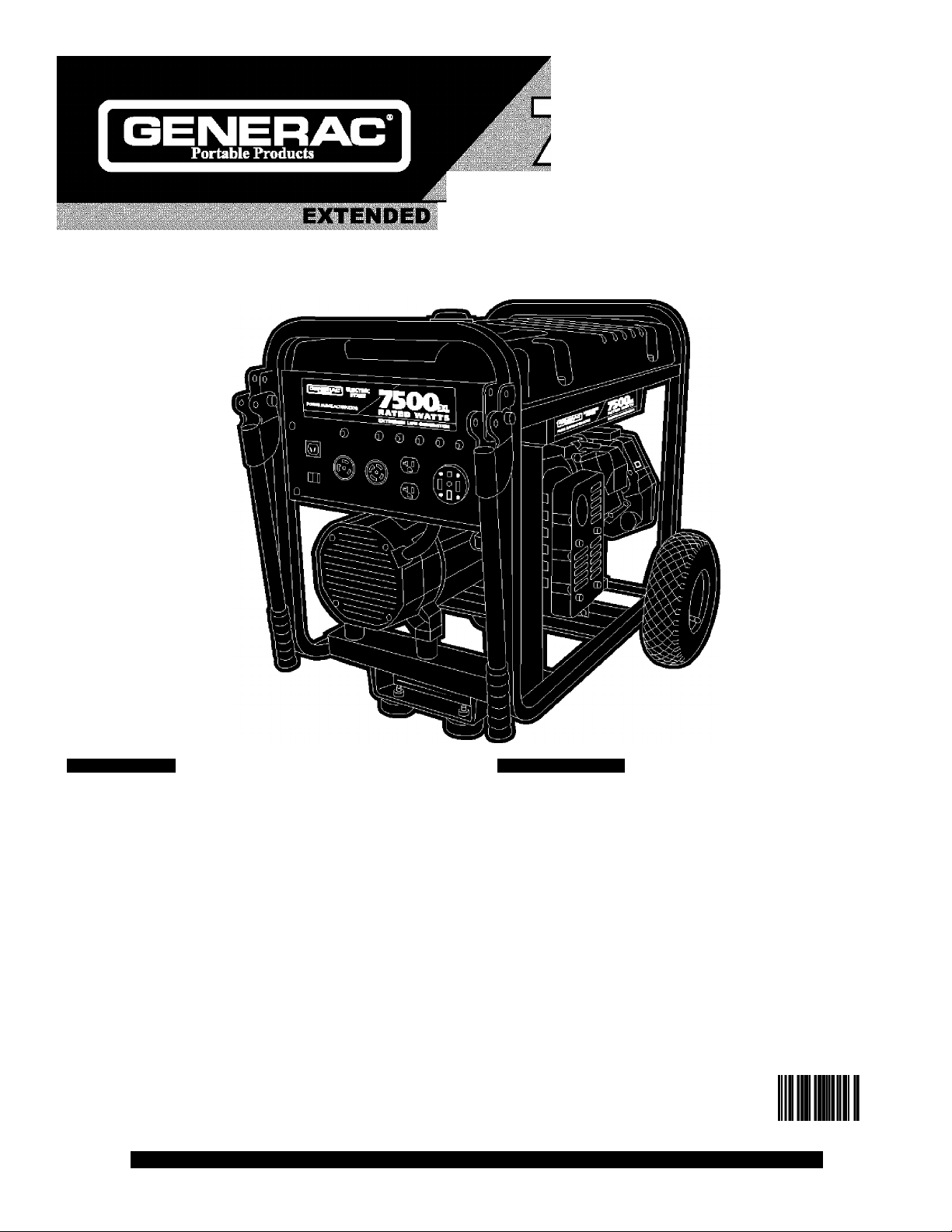
ATED WATT
LIFE GENERATOR
Owner's Manual
Parts Included*
• Generator
• Wheel kit
• Storage Cover
• Battery
• Battery Float Charger
• Battery Charge Cables
• Spare Spark Plug, Air Filter, and Oil Filter
• Spark Plug Wrench
• (2) Locking 30 Amp Plugs
• Engine Oil
• Oviiner's Manual
• Engine Manual
*lf any parts are missing or damaged, call 1-800-270-1408.
Questions? Help is just a moment away!
CalLGenerac Generator Helpline - 1-800-270-1408 M-F 8-5 CT
Web: www.generac-portables.com
Model No. 1019-3 (7,500 Watt AC Generator) Manual No. I897I3GS Revision 5 (12/18/2003)
Table of Contents
Safety Rules
Knov^ Your Generator
Assembly............................................................................6-7
Operation..........................................................................8-13
Product Specifications.......................................................14
Maintenance........................................................................14
Storage.................................................................................15
Troubleshooting..................................................................15
Schematic............................................................................16
Wiring Diagram....................................................................17
Replacement Parts
Notes....................................................................................23
Warranty
.......................................................................
.........................................................
........................................................
....................................................................
0"«24847"05311
2-4
18-22
Last Page
5
Page 2
EQUIPMENT
SAFETY RULES
DESCRIPTION
Read this: manual carefully and become
familiar with your ^^nerator. Know its
applications, its limitations and any hazards
involved.
The generators are an engine-driven, revolving field,
altsrnating current (AC) generator. It was designed to
supp y electrical power for operating compatible electrical
lighting, appliances, tools and motor oads.The generator’s
revo ving field is driven at about 3,600 rpm by a single-
cy inder engine.
CAUTION! DO NOT exceed the generator’s
wattage/amperage capaci^. See "Don’t Overload
Generator” on pa;^ 13,
Every effort has been made tx> ensure that information in
this manual is accurats and current. However, we reserve
the right to change, altsr or otherwise improve the product
and this document at any time without prior notice.
The Emission Contro System for this generator is
warranted for standards set by the Environmental
Protection A;^ncy, For warranty information refer to the
engine owner’s manual.
In the:State:ofGaiifOrhla: a spare arrester is :reqUlred: :by :laW:
(Section 4442
Other states wlay have similar laws. Federal law^ apply on
federai iandsulf you ecuic the muffler with a: spark arrester, :
itimust ibeimaintainedi in effecti\eiv«5rdng order
of the GàiifOriiia-Public- Riésourcés -Godè).
.............
A
The safe^ alert symbol (A) is used with a signal word
(DANGER, CAUTION,WARNING), a pictorial and/or a
safety messa;^ to alert you to hazards, DANGER indicates
a hazard which, if not avoided, will result in death or serious
injury, WARNING indicates a hazard which, if not avoided,
could result in death or serious injury, CAUTION
indicates a hazard which, if not avoided, m/g/it result in
minor or moderate injury. CAUTION, when used
without the alert symbol, indicates a situation that could
result in equipment damage. Follow safety messages to
avoid or reduce the risk of injury or death.
The engine exhaust from this product contains
chemicals known to the State of California to cause
cancer, birth defects, or other reproductive harm.
Hazard Symbols and Meanings
...........
This is the safety alert symbol. It is used to
alert you to potential personal injury hazards.
Obey all safety messages that follow this
symbol to avoid possible injury or death.
^WARNING
^ >
Electrocution Electrical Shock Electrical Shock.
M
Toxic Fumes
Explosive Pressure Chemica Burn Hot Surface
Explosion
Fire
Page 3
7500EXL Extended Life Generator
Id=lw^l=l=F±T-y
Parta DU rrodncti
^DANGER
Running generator gives off carbon monoxide,
an odorless, colorless, poison gas.
Breathing cai'bon monoxide will cause nausea,
fainting or deacii.
Qfxsratcl^nbrator ONJ' outdoors.
<ccp :àt: least :2| feet: of clearance ori all I sides of Igtìhbràtor for 11
adequate :ycntilation,
DO NOT operate: generator inside:an>' :building or:encbsurc,
includitig thci^ncratpr: TOmparoiiicnt of a: тсспж^рп^ lydiblq
WHEN ADDING FUEL
• Turn generator OFF and lot ic cool at least 2 minutes before
::: removing @»s| Cap. -oosen cap ;sloy^tp rdieTC|pressurc in rank.!
.
»:: Fill :fijel|tank outdoors. 11111111111111111111111111111111111111111111111111
• DO NOT overfill tank,Allow space for fuel expansion,
DANGER
Generator produces powerful voltage.
Failure to Isolate generator from power utility
can result In deatli or injury to electric utility
workers due to backfeed of electrical energy.
•;; vyhonl using gohej^r lfer backup pcwen lnotify utility 11111111111
::: Company,;Usc approved: transfer;equipment to isolate ;;;;;;;;;;;
;;; generator from electric uti)!^. II
•I I Use a groundl circuit fault interrupter l(GFCI)l in lany damp lor 11
highly conductive area, such as metal decking or steel work.
•I I DO F40~ touch bare Wirtsl Or receptacles.
• DO NOT use gonerabar with electrical cords which are worn,
111 fti^cd, bare or otherwise dama^d.l I
» DO NOT operate generator in the rain, u y
•I I DO NOT I handtel generator or electrical cor ds while Sttinding |
in water, while barefoot or while hands or feet are wet,
i>:: DO NO”a|tow lunqualifled;persons or children to operate or
111 service generator,! 11111111111111111111111111111111111111111111111111111111
*■; Keep fuel I awayi from; sparks, open ;flamts.| pilot lights, hear, and ;
other ignition sources.
• DO NOT light a ciprette or smoke.
WHEN OF>ERATING EQUIPMENT
•I I DO NOT Itiplengine orlixjurpment at angle which causes fuel
I to spill................................
• This generator is not for use in mobile equipment or marine
111 applications. 111111111111111111111111111111
WHEN TRANSPORTING OR REPAIRING EQUIPMENT
• Transport/repair with fuel tank EMPTY or with fuel shutoff
valve OFF.
• Disconnect spark plug wire.
WHEN STORING FUEL OR EQUIPMENT WITH FUEL
IN TANK
.
rl I Store:aw!y:fromlfu:maces,:stoves,vmtor heaters, clothes
111 dryers or other applimctalthai lhave pilot light or other 11111111
111 ighMph source | tecause they can ignite fuel vapors. |
Fuel and its vapors are extremely flammable and
explosive.
Fire or explosion can cause sevei e bui iis or
deatli.
^V^RNING
* •
...
;;
.........................
..
Ш Ш Ш
Storage batteries give off explosive hydrogen gas
dui'ing rechai'ging,
Hydi’ogen gas stays around battery for a long
time after battery has been charged.
Slightest spai'k will Ignite hydrogen and cause
explosion.
You can be blinded or severely injured.
Battery electrolyte fluid contains acid and is
extremely caustic.
Contact with battei'y fluid will cause sevei'e
chemical burns.
1 • DO NOT allow any open flame, spaHc, heat, or lit cigarcctc I
during and for several m
• Wear protective gosgli^
inutts after charging: a battery.:
, rubber apron, and rubber gloves.
~his generator docs not moot U. S. Coast Guard Regulatibnl
I SSGFR“ jSj and I should; not be used on marine applications.
I Failure to use the appropriate! U. S. Coast Guard lappnovedl 11
Igéhératór could result in bodily injury and/or property 111111
I damage.; ;;;;;;;;;;;;;;;;;;;;;;;;;;;;;;;;;;;;;;;;;;;;;
.........
Page 4

шштшшт
forbibk Prodicti
7500EXL Extended Life Generator
A WARNING
Exceeding generators wattage/amperage capacity can
Unintentional spai'king can result in fire oi'
electric shock.
WHEN
gene
i>:: OisGonnpct |tho Spark :pl pg wire; from: thpi spark; pi ug; and pjaco;
::: the WirC:WhCTC:lt :Cahhbt: COntaCC spark plug.:::::::::::::::::::::::
ADJUSTING OR MAKING REPAIRS TO YOUR
RA
iTOR
Щ Щ Ш Ш Ш
Running engines produce heat.Temperature of
muffler and neai'by areas can reach oi' exceed
I50T f65X),
Severe burns can occur on contact.
: DO h40~ touch hot sur&ces.: i i i i i i i i i i i i i i i
; ^ low equipment; № gqqI; bqfp touehihg.
Ж CAUTION
Excessively higli opeivating speeds increase risk of injury
and damage to geneivatot:
Excessively low speeds impose a heavy load.
DO NOT tamper with governed speed. Generator supplies
correct rated frequency and voltage when running at governed
speed, ;;;;;;;;;;;;;;;;;;;;;;;;;;;;;;;;;;;;;;;;;;;;;;;;;;;;;;;;;;;;;;;;;;;;;;;
DO NOTImbdii^ gohoratdrfnlahylmy.: 11111111111111111111111111111
damage generator and/or electrical devices connected
*;; See “Opn'tiOyerlpad ;Gensratpri*; on page 13.
•:: Start gcheratbrand: let engine stahilrzel before connecting: 11
;;; eliectriiat ibadsi 1111111111111111111111111111111111111111111 k
•:: Connect:electrical: loads:in: OFF :pos№on.then turn GN for
::: bfXSI^oh.::::::::::::::::::::::::::::::::::::::::::::::::: k
Turn;dectrical; loads ;OPF; and disconnect fram; generator;;;
before Upping generator. ;;;
Improper treatment of generator can damage it and
shoi'ten its life.
•;; Use; generator brily for intended; uses.
• If you have questions about intondtsd use, ask dealer or call
I -8Da-2H)-IdOS.
• Operate gonorator only on level surfaces.
• DO NOT expose generator to excessive moisture, dust, dirt,
;;; br:C0rri3S)¥C:VapbrSi::::::::::::::::::::
•:: DO NOT Insertjany:objects;through cooling slots,
•; ; If ebnnectod dbviciS QVcrhbat. turn them off and disconnect
them from generator,
•:: Shut off generator if:
;;;;;;;;; -electrical output is lost:
;;;;;;;;; -equipment ;spark3,;siT1bkbs,; or ;emte flarnes;;;;;;;;;;;;;;;;;
......... vibrates excessively.
CAUTION
.......
CAUTION
...............................
Page 5
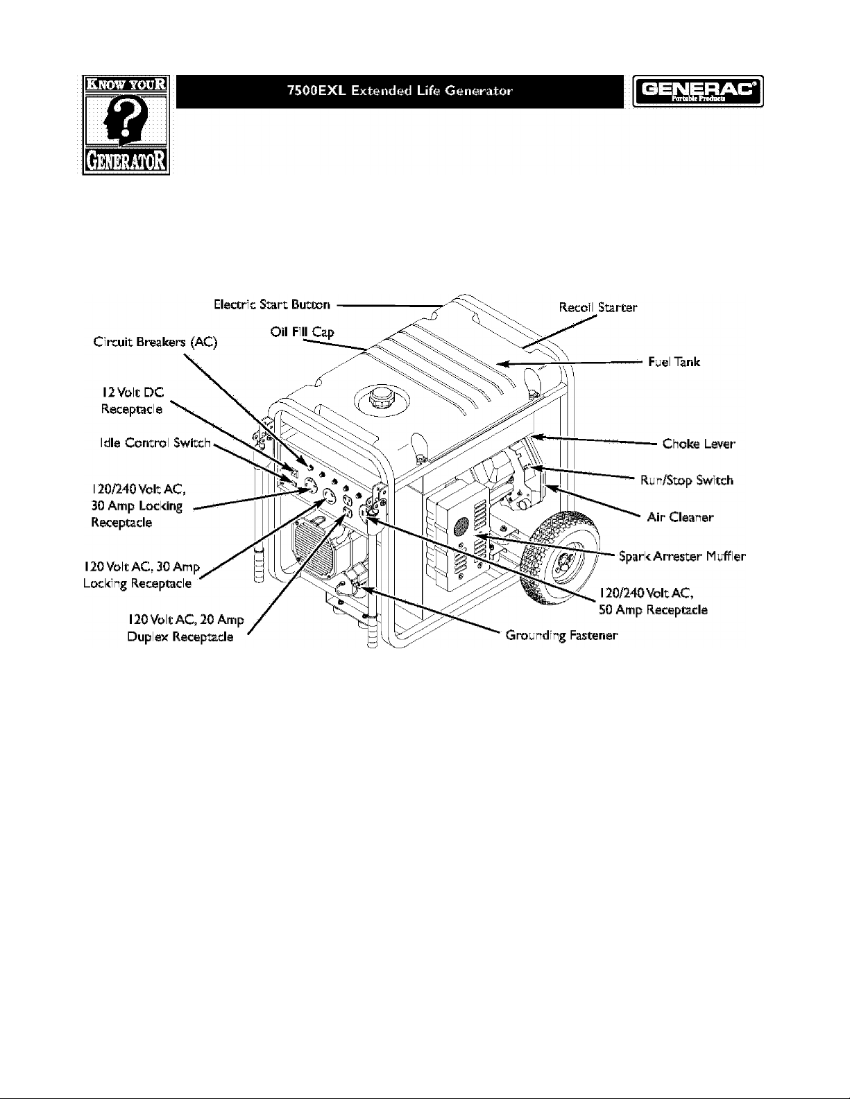
KNOWYOUR GENERATOR
Read this owners manual and safety rules before operating your generator.
Compare the illustrations with your generator, to femiliarize yourself with the locations of wirious controls and
adjustments. Save this manual for future reference.
; 12 Volt pc ; Receptacle 1^ Use this I receptacle w’tfi
battery charge I cables l&i Ichairge I a 112Vólt baittèry. Il II II II II II II II
Il2blVdltACfl2ÒAmp Duplex Rècéptacléli-I-I- May be
lùislédltbl isltij3j2lyl electrical Ipc^er fori the operaio ' of
|j2QYoItlAGilsihj^e phase.60 I Izlélectlriléallllightingi.làpplliahce.-
Itpoli and; motor iloadis.i 1111111111111111111111111111111111111
i j 20iVbjt ACti30 Amp iLocking iRecejAaclei i— May be
used|toi supplyelectrical ip^erifòrithe lopertópn ;pf...........
: 120 Volt AG, 130: Amp,l single | phase, 601 Hz I electrical llìghtìng,
lajjpliahceljltoòll land Imbiioir I Heads; 11111111111111111111111
Il 20/240 yoltlAC,l30 lArnpl ILockingl Receptacle — May
Iblei usèdi Ito Isupp y lelèctricàJl power fòr thel opèratiort cf
I j 20 and/or 24Ól¥óllt AC. |3Q Amipj islh^él phase, 60 Hz
iejectrical; iightjng,appliance;,itooi land ; motor; loads,; ; ;;;;;;;;
120/240 VoltAdC^ 50 Amp i^ceptade ™ May be used
to supply eiectrical povrer for the operation of 240 Vo t AC.
50 ;Amp,;slngle Iphase, 60 ;Hz leiectrlcal; loads. ;;;;;;;;;;;;;;;;;;
Air iCleaner l-^l Uses; a dry ^pe filter; element and foam
Ipire^leanerltol mit thel amount I of dirt and I dust i sucked I
intol the lengine. 1111111111111111111111111111111111111111111111111111111111
' Choke Lever Used whehlstariilng a cold; e-gi-e.
.......
i iCii-cuitiBreatere pC) Each receptaclei isi provided i i i i i
: :with: al "pUSh: iiXJ: itieset'' :circuit :brea!cer 'to. :p:ratect: the
I generator lapinlstl eleittrical loverioad, 11111111111111111111111111111111
I iFuel Tank ~l Cajsadtyl of seven I (7) I U.S. gallons. 111111111111111
; ;E jectric; S^rt ;Switch Press ;to ;start the; engine,;;;;;;;;;
: :G№und|ng; Fastener—;|f;required,; please ;consu ;;;;;;;
cual;ifjed;eleGtricia"*, electrical inspector, or ccal agency ;
'•avlhg jurisdictio", ; ;
Idle iGlOntrall iSwitch — Tre id e control runs the engine
at ;nprhial; ;(h!gh); ;speeds;when ;there; is; a; load; present ;and
r'un;s;the ;engine ;at idle ilpy/j ;speeds: when a load is not
..
I Ipriesentt: 111111111111111111111111111111111111111111111111111111111111111111111111
Oil Fill Cap — Add oil to engi ne here.
Recoil Starter — Used to start the engine manually,
Run/Stop Switch — Must be in “Run” position to start
ertgine. Set to “Stop” to stop a running engine.
SparkArresteriMuffler-^:Exhaust muffler lowers engine
; ;noise; and; is equipped; with a;spar4arrester screen.
..........
............
..............
;
.....
Page 6
ASSEMBLY
Your generator requires some assemb y and is ready for
use after it has been praper y serviced with the
recommended oil and fuel.
If you have any problems: with the assembly of your
generator, please call the generator helpline at
1-800-270-1406.
IMPORTANT: Any attempt to run the unit before it has
been serviced with the recommended oi will result in an
engine ^ilure.
Remove Generator From Carton
1. Set carton on a rigid flat surface with “This Side Up”
arrows pointing upvrard.
2. Carefully open top flaps of shipping carton. Review
"Cold Weather Operation” on page 10,
3. Cut down corners at one end of carton from top tx>
bottom and lay that side of carton down flat
4. Remove all packing materia, carton fillers, etc,
5. Remove the generator from the shipping carron.
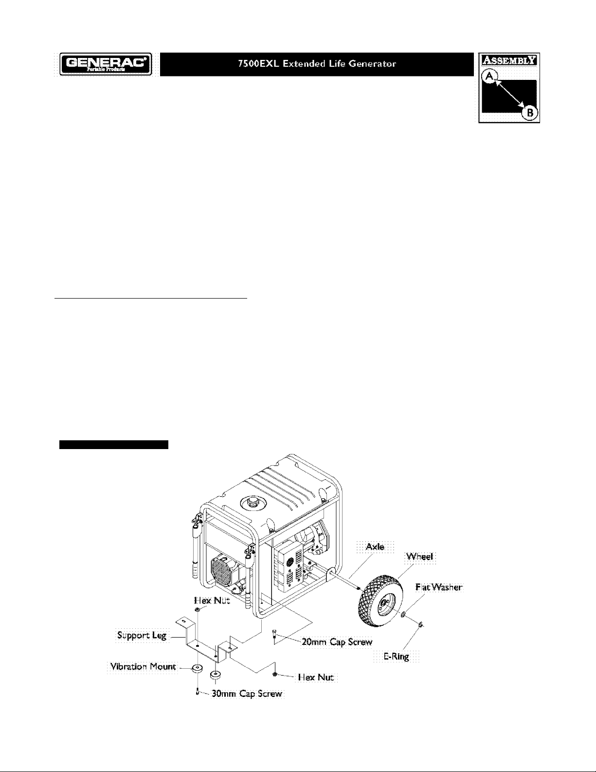
Install Wheel Kit
The wheel kit is designed to greaty improve the portability
of your generator.
NOTE; Whee kit is not intended for over-the-road use.
You will need a socket wrench with 1/2” or 13mm sockets
and a need e-nose p ier to install this kit.
Refer to Figure I and install the wheel kit as follows:
I.
Place the bottom of the generator cradle on a flat,
even surfice.Temporarily place unit on blocks to ease
assembly.
2.
Slide axle through both axle mounting bracl@ts on
cradle frame, as shown in Figure I,
3.
Slide a whee over the axle.
NOTE; Be sure to install both whee s with the air
pressure valve on the outboard side.
4. Place the e-ring onto the groove in the axle,You may
add the flat washer if desired.
NOTE; Use retaining pins instead of e-clip, if app icab e,
5. Place one end of the needle nose p iers on the bottom
of the ax e and the other end of the pliers on top of
the e-ring. Seat the e-ring by pressing the p iers closed.
6. Repeat step 3 through 5 to secure second wheel.
Figure I —liistallWhccI Kit
Page 7
7500EXL Extended Life Generator
Id=lw^l=l=F±T-y
Farta DU rrodncti
7. Remove the temporary blocks.
8. Ata,di the vibration mounts to the support eg with
30mm capscrews, vrashers and lock nuts,
9. With the wheels on, you can now lift up the handle
end and attach the support leg with 20mm cap screws
and lock nuts.
ID. Check that a I fasteners are tight and the tires are inflated
to the та1ие marl®d on the tire or within 15 and 40 psi.
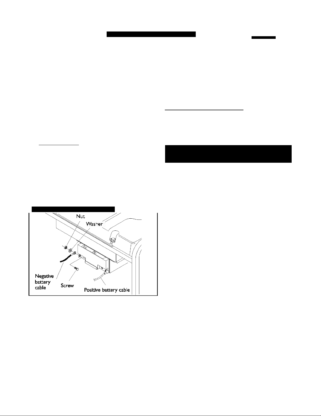
Check Battery / Attach Negative
Battery Wire
The sealed battery on the generator is fully charged and
pre-installed except for the ne;^tive (blacic) battery cable.
To install:
1. Cut off tie wrap securing oose end of ne;^tive (b ack)
cable.
2. Remove nut and v^isher on neptive battery terminal.
3. S ide negative battery cab e over screw on ne;^tive
terminal (Figure 2),
Figure 2— Negative Battery Connection
____________________
BEFORE STARTING THE
ENGINE
Add Engine Oil and Fuel
• Place generator on a level surface.
• Refer to engine owner’s manual and follow oil and fuel
recommendations and instructions.
CAUTION
Any
attempt to crank or stai't the engine before it has
been propei'ly filled with the recommended oil
in equipment failure.
; Refer to engine manuai for oil; and fuel fill information,
: Damage tol equilpmant resulting from failure to follow this
; instruetioh will void warranty.
NOTE; Check; oil often during engine break—in. Refer to
engine owner’s manual for recommendations,
NOTE: The generator assemb y rotates on a prelubricated
and sealed ball bearing that requires no additiona
lubrication for the life of the bearing.
will
___________
I'esult
.....
4. Reattach washer and nut and tighten.
5. Verify that connections to battery and generatx>r are
tight and secure.
Page 8

шштшшт
forbibk Prodicti
7500EXL Extended Life Generator
USING THE GENERATOR
System Ground
The generator has a system ground that connects the
generator frame components to the ground tormina s on
the AC output receptacles.The system ground is connected
to the AC neutral wire (see "Equipment Description”,
eariier in this manua).
Special Requirements
There may be Federal or State Occupationa Safety and
Health Administration (OSHA) regu ations, local codes, or
ordinances that app у to the intended use of the generator.
Piease consuita qualified eiectrician, eiectricai inspector, or
the loca agency having jurisdiction,
• In some areas, generators are required to be registered
with bcai utiii^ companies,
• If the generator is used at a construction site, there may
be additionai reguiations which must be observed.
Connecting to a Building’s Electrical
System
Connections for standby power to a building’s e ectrica
system must be made by a qua ifled eiectrician. The
connection must isolate the generator power fram utiiily
power, and must сотр у with a I app icab e aws and
electrical codes.
_____________________
How to Use the Battery Charger
Use battery float charger jack to keep the starting battery
charged and ready for use. Battery charging should be done
in a dry bcation, such as inside a ;^rage,
• Plug the charger into the unit’s “Battory Float Char^r”
jack, which is located on the starter switch (Figure 3).
Plug battery charger into a 120 Volt AC wal recepto.de.
Figure 3 — Battery Cliaigcr Jack
■) j''
• Unp ug the char^r from the unit and the wall outlet when
generator is being started and while it is in operation.
• Keep this charger plugged in when generator is not in
use to prolong battery ife.The charger has a built in float
equalizer and will not overcharge the battery, even when
plugged in for an extended period of time.
IMPORTANT; See “Battery Maintenance” on page 14 for
additional information,
OPERATING THE
GENERATOR
IMPORTANT; A wa)^ unplug the battery float charger
before starting the generator.
Generatoi' produces powerful voltage.
Failure to Isolate generator from power utility
can result In deatli or injury to electric utility
workers due to backfeed of electi'ical energy.
VyhRh; using generator ifbr backtip powenihotily iutiiity i i 111111111
ccMT|pany.:Use appraved: tranter: qquipmqnc to isolate
gerieiatbr froffi electric Utili^i::::::::::::::::::::::::::
Use a ground: fault idrcult interrupter (C-C) in any idarfip ibr::
highly conductive; areavSUGh as ;metef decking or steel work,
30 NOT touch I bare wlrt»: br rbcoplaclcs.i i k k k k
:DO: NOT use: generator with electrical: cords which are vtrorn,
fti^cd, bare;or:othcrwise damaged.
DO NO~ operate generator in the tain,
DO NOT handle generator or electrical cords while standing
in watenwhiic barefoot or while hands or foot arc wet.
DO NOT al low unqualifled persons or children to operate or
service generator:^
.....
......
.
Exceeding generators watcage/amperage capacity can
damage generator and/or’ electrical devices connected
•:: Sbe ■‘DQfi’tlOveriQad iGchdratbr^ ■ bh ppgcl 13. I
*:: Start gGncf^tqr:an(d: jot onginc 5toi>t|rzc before connecting;;;
::: elCCttiral: llbads;::::::::::::::::::::::::::::::::::::::::::::::: k
*;; Gbririoct electrical loads in OFF positron, then turn ON for
;;; qpet^pn,;;;;;;;;;;;;;;;;;;;;;;;;;;;;;;;;;;;;;;;;;;;;;;;;;;;;;;;;;;;;;;;
•:: Turn: cjcctrical: loads :0:FF: affd :disc6hnect from generator
;;; befcre stbpprr|g;generi№brt;;;;;;;;;;;;
eAUTION
Page 9

Щ
Ш
7500EXL Extended Life Generator
Id=lw^l=l=F±T-y
Porteble rrodech
Starting the Engine
Disconnect all electrical bads from the generator. Use the
following start instruction steps by numerica order:
1. Mate sure unit is on a level surface,
IMPORTANT: Failure to start and operate unit on a level
surface wi I cause the unit not to start or shut down during
operation.
2. Turn the fuel valve to the “On” position (Figure 4),The
fuel va ve handle should be vertical (pointing toward
the ground) for fuel to flow.
Figure 4 — FucIValvc
Fuel Valve its; shown
in the; Oh;position;
3. Mate sure the Id e Control switch is in "Off” position
(Figure 5).
Stopping the Engine
1. Unp ug all e ectrical loads from generator panel
receptacles. NEVER start or stop engine with electrical
devices plugged in and turned on.
2. Put idle control switch in “Off” position,
3. Let engine run at no-load for 30 seconds to stabilize
internal temperatures of engine and generator.
4. Turn engine off according to instructions given in
engine owner’s manual,
5. Move fuel valve to “Off” position.
Operating Automatic Idle Control
This switch is designed to greatly improve fuel economy.
When this switch is turned ON, the engine will only
run at its normal high governed engine speed when an
e ectrical load is connected.When an electrica load is
removed, the engine will run at a reduced speed. With the
switch off, the engine wi I run at the normal high engine
speed. Always have the switch off when starting and
stopping the engine.
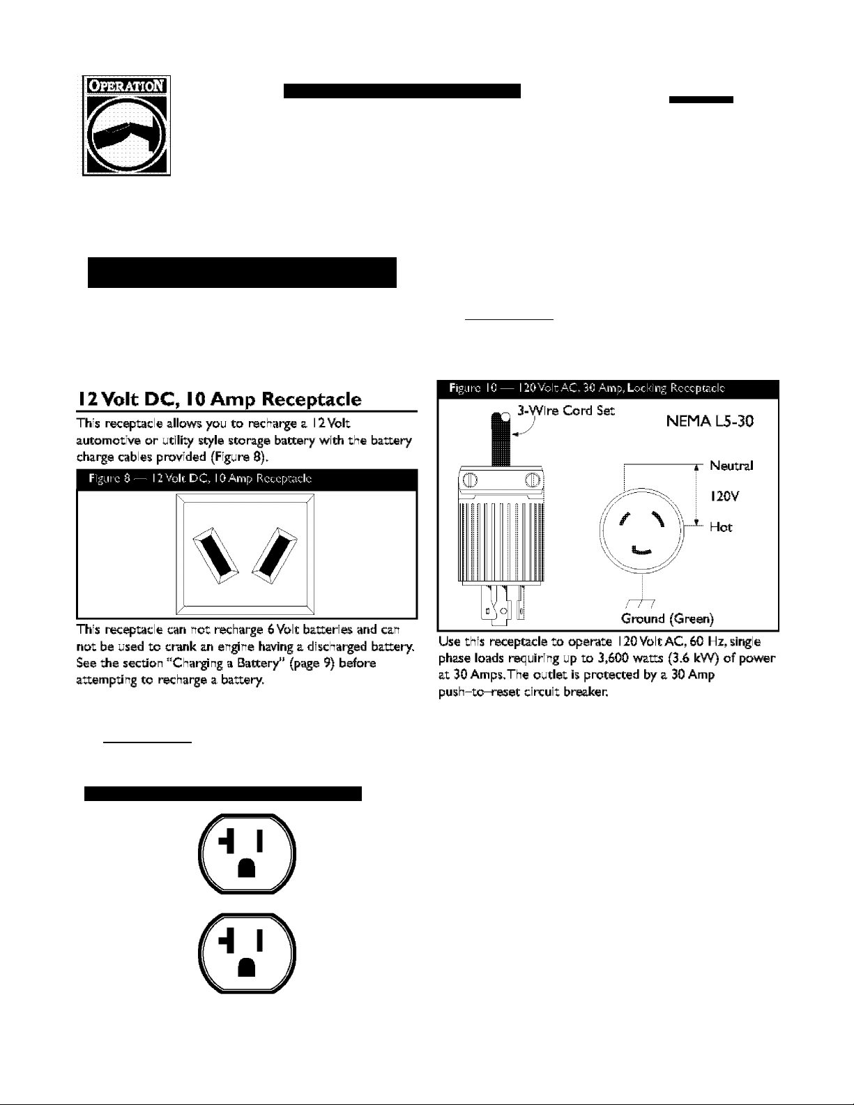
Charging a Battery___________________
Your generats>r has the capability of recharging a discharged
12 Vo t auts>motive or utility style storage battery. DO
NOT use the unit to charge any 6 Volt batteries, DO NOT
use the unit to crank an engine having a discharged battsry.
4. Start the engine according to instructions given in the
engine owner’s manual.
NOTE; If engine starts after 3 pu Is but fai s to run, or if
unit shuts down during operation, mate sure unit is on a
level surface and check for proper oil level in crankcase.
This unit may be equipped with a low oil protection device.
See engine manual.
Connecting Electrical Loads
• Let engine stabilize and warm up for a few minutes after
starting.
• Plug in and turn on the desired 120 and/or 240 Volt AC,
single phase, 60 Hz electrical loads.
• DO NOT connect 240 Volt bads to the 120 Vo t
receptacles.
• DO NOT connect 3-phase loads to the generator.
• DO NOT connect SO Hz loads to the generats>r.
• DO NOT OVERLOAD THE GENERATOR. See
"Don’t Overbad Generator” on page 13.
* •
Ж e^ancer
Storage batteries give off explosive hydrogen gas
diii'ing recharging.
Hydrogen gas stays near battery foi' a long time
after battery has been charged.
Slightest spark will ignite hydrogen and cause
explosion.
You can be blinded or severely injured.
Battery electrolyte fluid contains acid and Is
extremely caustic.
Contact wicli battery fluid will cause severe
chemical burns.
*;; DO;NOT ;allqw any open ;flame,;3park,; htsat;qr lit; cigarette
;;; during; and for several minutes after charging a battery,
•;; Wear; protecfyo gb^lesi rubber; apron, and rubber gloves.
To recharge 12 Volt batteries, proceed as follows:
I. Check fuid level in all battery cells. If necessary, add
ONLY distilled vsiter to cover separators in battsry
ce Is. DO NOT use tap water.
Page 10

fortiibk Prodicta
7500EXL Extended Life Generator
2. If battery is equipped with vent caps, make sure they
are installed and are tight.
3. If necessary, clean battery termina s,
4. Connect battery charge cab e connector plug to panel
receptac e identified by the words "12-VOLTS D.C.”
5. Connect battery charge cab e c amp with red handle
ts> the positive (+) battery terminal (Figure 6).
Figure 6— Battery Connections
Connect battery charge cab e c amp with black handle
6,
the negative (-) battery terminal (Figure 6).
7. Start engine. Let engine run whi e battery recharges.
8. When battery has charged, shut down engine
NOTE: Use an automotive hydrometer to tBSt Ixittery sate
of charge and condition. Follow the hydrometer
manufecturer^s instructions careful y. Genera ly a battery is
considered to be at 100% state of charge when specific gravity
of its fluid (as measured by hydrometer) is 1.260 or higher.
Bui d a structure that will enclose three sides and the top
of the generator,
I. Mai® sure entire muffler-side of generator is exposed.
3.
4.
Note that your generator may appear different from
that shown in Figure 7.
Figure 7 — Pcrmaiiciu Cold Wcatiicr Shelter
side of box and nearest object
Face exposed end avray from wind and elements.
Enclosure should hold enough heat created by
generator to prevent problems,
^DANGER
Running generator gives off carbon monoxide,
an odorless, colorless, poison gas.
Bi'eathing carbon monoxide will cause nausea,
fainting or death.
COLD WEATHER
OPERATION
Under certain weather conditions (temperatures below
40°F [4*C] and a high dew point), your generator may
experience icing of the carburetor and/or the crankcase
breather system.
•IIQpcraitelgciicratorGNLY: outdoors.
*■ ■ Keep at (past 1: foot of clcar^ncp; on: all sides of generator for
i i i adequate ventilstibh.: 111111111111111111111111111111111111111 h
•:: DOINGTIoperabiilgerieriadsi’ insicfelary buiHing or erdosure,
;;; indud|rig;tjys|gener^r compare itscr^pnal vchido
•:: Rdrhovc gonotatdrlfromlsheltcr when torTtporaturcl Is I above I
........
Page 11
7500EXL Extended Life Generator
Id=lw^l=l=F±T-y
Porteble rrodech
RECEPTACLES
...................
Receptacles may be marked wtdi rating value greater
than generator output capacity.
NEVER, latt^mpttpippwara device irequiringi more
amperage ithanigeneratPPiP :receptac)eican supp y.; y y y
DO NOT overload the ;^neraton See "Don’t Overload
Generator”,
........ C^UTiON
Use each recepude to operate 120 Volt AC, single-phase,
60 Hz electrical loads requiring up to 2,400 mtts (2.4 kW)
at 20 Amps of current. Use cord sets that are rated for
125 Vo t AC loads at 20 Amps (or greater),
120 Volt AC, 30 Amp Locking
Receptacle
Use a NEMA L5-30 plug with this lecepude. Connect a
3-^ire cord set rated for 125 Vo t AC loads at 30 Amps to
the plug (Figure 10),
______________________
120 Volt AC, 20 Amp, Duplex
Receptacle
Each receptac e (Figure 9) is protected against overload by
a 20 Amp push-to-reset circuit breaker.
Figure 9— l20VoltAC.2€ Amp, Duplex Receptacle
______________________
Page 12

шштшшт
forbibk Prodicti
7500EXL Extended Life Generator
120/240 УШ AC, 30 Amp, Locking l 20/240^lt AC, 50 Amp Receptacle
:::::: :|%6С0рШС||О i i i i i i i i i i i i i i i i i i i i i i i i i i i i i Ш Use NEMA 1^30 :pJÜg With thfS :ГеСерШс1е: (Figure: 12).::
Use a; NEMA;u ^30. p!;:g w=th.this. receptada. Connect a. ^™®-t^.;4.™re.ccrd;3etra^^^^ 230VotAC loads atll
ne:cord Isett Inrted: for 250 yqlt AGI loads at: 30 Amps (or 11111
greater): (Figure! f II) Той I cari I use Itttel same I4l-iwiral cord Í 1111
yotil piahitbl rúlnia I liO^oitl load; 111111111111111111111111111111111111111111
Figure 11 — 120/240 Volt AC, 30 Amp Rcccptadc
: 4‘'Wtre :Gord: Set:
--
-----------
240V
----------
I
^2GV-T^I20V-<-
{ )
►
I ■ W (Neutral)
Figure 12— 120/240VokAC, SOAmp Rcccpcadc
240 Volts AG
Frame Ground
ll
Y (I lot)
X (Hot)
//
Y (Hot)
NEMA LI4-30
This receptae e powers l20/240Volt AG, 60 Hz,single
phase loads requiring up tti 3,600 watts of power at
30 Amps fcr 120 Volts; 7,200 vratts of povrer (7.2 <W) at
30 Amps; for 240 yo|ts;.Ti?e;outlet Is pretected; ;Ьу a; 30 Amp;
pusr-tó;-iesét; circuit bleaker,.
71 Ground! (Green) I
X (Hot)
Use :this: receptacle to :c^erate: 120/240 Volt AC, 60 Hz, ;
single phase loads requirVig up to 7,500 watts (7.5 kW) of
power. The outlet is protected by a 33 Amp push-to-reset
circuit breaker.
120 Volts
AC
W (Neutral)
NEMA 14-50
120 Volts
AC
Page 13
7500EXL Extended Life Generator
Id=lw^l=l=F±T-y
Porteble rrodech
DON'T OVERLOAD
GENERATOR
Capacity
You must make sure your generator can supp y enough
rated (running) and surge (starting) vfiitts for the items you
will power at the same time, Fo low these simple steps:
1. Select the items you will power at the same time.
2. Total the rated (running) vratts of these items.This is
the amount of power your ;^nerator must produce to
keep your itoms running. See Figure 13.
3. Estimate how many surge (starting) watts you will
need. Surge vrattage is the short burst of power
needed to start electric motor-driven tools or
appliances such as a circular saw or refrigerator.
Because not all motors start at the same time, tx>tal
surge watts can be estimated by adding only the
item(s) with the highest additional surge watts to the
total rated watts from step 2.
Example;
Tool or Appliance
Window Air
Conditioner
Refrigerator
Deep Freeaor
Television:
Light (75: Watts):
Toul Rated (Running) Watts = 3075
Highest Additional Surge Watts =1800
Total Generator Output Required = 4875
Power Management
To prolong the ife of your generator and attached devices,
it is important to take caro when adding electrical loads to
your generator.Thero shou d be nothing connected to the
generator outlets beforo starting it s engine.The correct
and safe vray to manage generator power is to sequentially
add loads as follows:
1. With nothing connected to the generator, start the
engine as described in this manua.
2. Plug in and turn on the first load, preferab y the largest
load you have.
3. Permit the generator output to stabilize (engine runs
smoothly and attached device operates properly.
__________________________
Rated (Running)
Watts
.......
I2ÍK)
800
500
500
175.
I T3075ITcatall III III III TISOOlHiglu^l I
I Running Wattsi 11111111 li&rgeWatK 11
Addidonal Surge
; (Starting; Watts: I
iSOO
Í600
500
4. Plug in and turn on the next bad,
5. Again, permit the ;^nerator to stabi ize.
6. Repeat steps 4 and 5 for each additional load.
NEVER add more loads than the generator capacity.Take
special care t» consider surge loads in generator capaci^,
as described above.
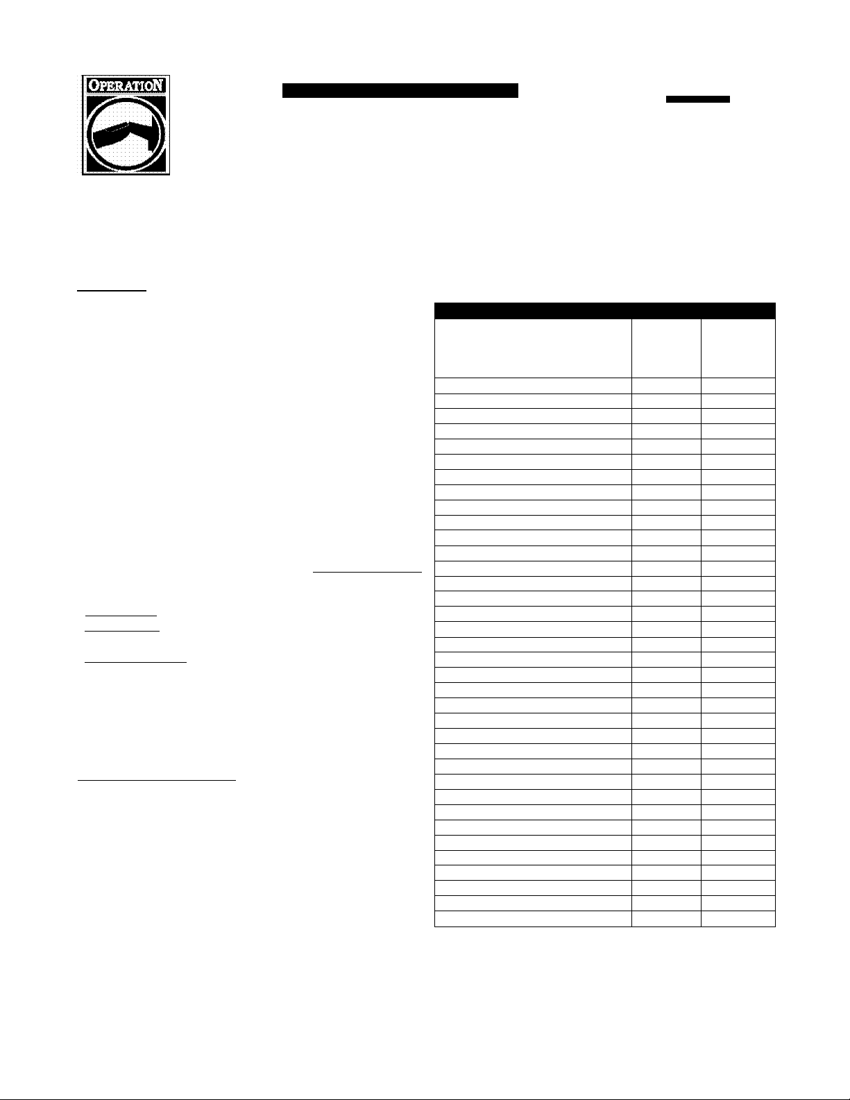
Figure 13 - Wattage Reference Chart
Rated*
Tool or Appliance
Essentials
Light Bulb - 75 watt 75
Deep Freezer
Sump Pump
Refrigerator/Freezer - 18 Cu. Ft
Water Well Pump - 1/3 HP
Heat1ng/Cool1ng
Window AC - 10,000 BTU 1200 1800
Window Fan
Furnace Fan Blower - 1/2 HP
Kitchen
Microwave Oven - 1000 Watt 1000
Coffee Maker
Electric Stove - Single Element 1500
Hot Plate 2500
Fartiily Room
DVD/CD Player
VCR 100
Stereo Receiver
Color Television - 27”
Personal Computer w/l 7” monitor 800
Other
Security System
AM/FM Clock Radio
Garage Door Opener - 1/2 HP
Electric Water Heater - 40 Gallon
DIY/Job Site
Quartz Halogen Work Light
Airless Sprayer - 1/3 HP
Reciprocating Saw
Electric Drill - 1/2 HP
Circular Saw - 7 1/4” 1500 1500
Miter Saw - 10” 1800 1800
Planer/lointer - 6”
Table Saw/Radial Arm Saw - 10” 2000 2000
Air Compressor - 1 -1 /2 HP
WVattages isted are approximate only. Check tool or
app iance for actúa wattage.
(Running)
Watts
500 500
800 1200
800 1600
1000 2000
300 600
800 1300
1500
100
450
500
ISO
300
480 520
4000
1000
600 1200
960 960
1000 1000
1800 1800
2500 2500
Additional
Surge
(Starting)
Watts
-
-
-
-
-
-
-
-
-
-
-
-
-
-
Page 14

fortiibk Prodicta
7500EXL Extended Life Generator
SPECIFICATIONS
Maximum Surge Watts..............................
Continuous Wattage Capacity
Power Factx>r
Rated Maximum Continuous AC Load Current:
At 120 Volu.................................................62.5 Amps
At 240 Volu.................................................31.2 Amps
Phase
..................................................................
Rated Frequency .............
Fuel Tanic Capacity
ShippingWeight
............................................................
............
...............
..................
......................................................................
.................... 7 U.S. gallons
..................
13,500 watts
7,500 watts
.............
1.0
I-phase
240 bs.
GENERAL MAINTENANCE
RECOMMENDATIONS
The Owner/Operator is responsible for making sure that
all periodic maintenance tasks are completed on a timely
basis; that all discrepancies are corrected; and that the unit
is kept clean and proper y stored. NEVER operate a
damaged or defective generator.
Engine Maintenance
See engine owner’s manual for instructions.
Avoid prolonged or repeated skin contact with used
motor oil.
Used wQisr |oih has shown; ts; cause cancer in
certain: jaboTatory animals.;;;;;;;;;;;;;;;;;;;;;;;;
ThoTOugh^imshlexposed areas: with soap and watch 111
KEEP OUT OF REACH OF CHILDREN. DON’T
POLLUTE. CONSERVE RESOURCES. RETURN
USED OIL TO COLLECTION CENTERS.
Generator Maintenance
Generator maintenance consists of keeping the unit clean
and dry. Operate and stor^ the unit in a clean dry
environment where it will not be exposed to excessive
dust, dirt, moisture or any corrosive vapors. Cooling air
slots in the generator must not become clogged with snow,
leaves or any other foreign material.
NOTE; DO NOT use a prden hose to clean generator.
Water can entsr engine fue system and cause prob ems. In
addition, if water enters generator through coo ing air slots,
.60 Hertz
some of the water will be refined in voids and cracks of
the rotor and statx>r winding insulation.Watsr and dirt
buildup on the generator interna windings will eventua ly
decrease the insulation resistance of these windings.
Battery Maintenance
Other than float charging, described elsewhere, no
maintenance is required for the battery. Keep the battery
and terminals clean and dry.
IMPORTANT; Battery charging should be performed in a
dry location, such as inside a garage.
To Clean the Generator
• Use a damp cbth to wipe exterior surfaces clean.
_______________
CAUTION
Improper ti'eatment of genei'ator can damage it and
shoi'ten its life.
DO; NOT expose ;gehera1fer:tQ:exce33lye moiscure, dust, dire,:
pr;c;prresiye;yappr3,;;;;;;;;;;;;;;;;;;;;;;;;;
DO:NOT:ihsert:ariy:dbjectS:thrQUgh:COOling:Slot3::::::::::::::
Use a soft bristle brush to loosen caked on dirt or oi
Use a vacuum cleaner to pick up loose dirt.
Use low pressure air (not to exceed 25 psi) to blow
away dirt. Inspect coo ing air slots and opening on
generator.These openings must be kept clean and
unobstructed.
......................
Page 15

7500EXL Extended Life Generator
Id=lw^l=l=F±T-y
Parta DU rrodncti
STORAGE
The generator should be started at least once every seven
da)ra and a lowed to run at least 30 minutss. If this cannot
be done and you must store the unit for more than
30 days, use the following guidelines to prepare it for
storage.
Generator Storage
• C ean the generator as outlined in “To Clean the
Generator.”
• Check that cooling air slots and openings on generator
are open and unobstructed.
Storage covers can be flamntnble.
; DO NOT; place a stora^ cover; over a; hoi gororaton ;;
: LoC equipment cool for a sufficient time before placing the
: cover on the equipment:::::::::::::::::::::::::::::::::
__________________
WARNING
Engine Storage
See engine owner’s manua for instructions.
Other Storage Tips
To prevent gum fram forming in fue system or on
essential carburetor parts, add fuel stabilizer into fuel
Шпк and fil with fresh fue, Run the unit for several
minutes to circu ate the additive through the carburetor.
The unit and fue can then be stored for up to
24 months. Fue s^bilizer can be purchased loca ly,
DO NOT store fuel from one season to another unless
it has been treated as described above.
Replace fuel conuiner if it surts t» rust. Rust and/or dirt
in fuel can cause problems if it‘s used with this unit.
Store unit in a clean and dry area.
TROUBLESHOOTING
РтоЫепп
No ДС output is available,
but engine is running.............
Engine runs good at: no^:
I load but
iwhién; ioadis connected.
Engine will not starts or
starts and runs njugh.
Engine shuts down during
operation, ...............................
Engine lacks power.
■ down”
Cause
: One :of thé:CÌrCUÌt:brèaterS:ÌS: Орёп;
2, : : : Faultin generator"
3. : : : РООГ: СОППесИОП :ЬГ: defective cor d set.: : :;3.;;;;Check; and; repair
4, Connected; device ;is; bad.
I , Short circu Ч in a co'^ected toad,
2. Ge-erator’s overoaded.
3, Shorted generator c rcuit.
1; Fuel iValve; is; in the; “Off'; position.;
2.;;; Failed; battery.
Out ;of gasoline,; Fill fuel;tank.
Load ;ls;too; high,; See "Don’t O^rload Generator".
...............................
Correction
....
1. Reset dixutt breaker.
2, Contact Generile service facility.
.....................
4, Connect another; device; diat;is ; in
.......
good condit on. ...........................
; Diisconh:ect;s;horted; electrical ;|cKid,
iSeel-'Dlbn-tOverload Generator".;
Contact Ge~erac service fecility.
;Turn; ;fuel та1Уе to ‘'On" position.
Rep ace battery.
Page 16

шштшшт
forbibk Prodicti
SCHEMATIC
7500EXL Extended Life Generator
тага
Page 17
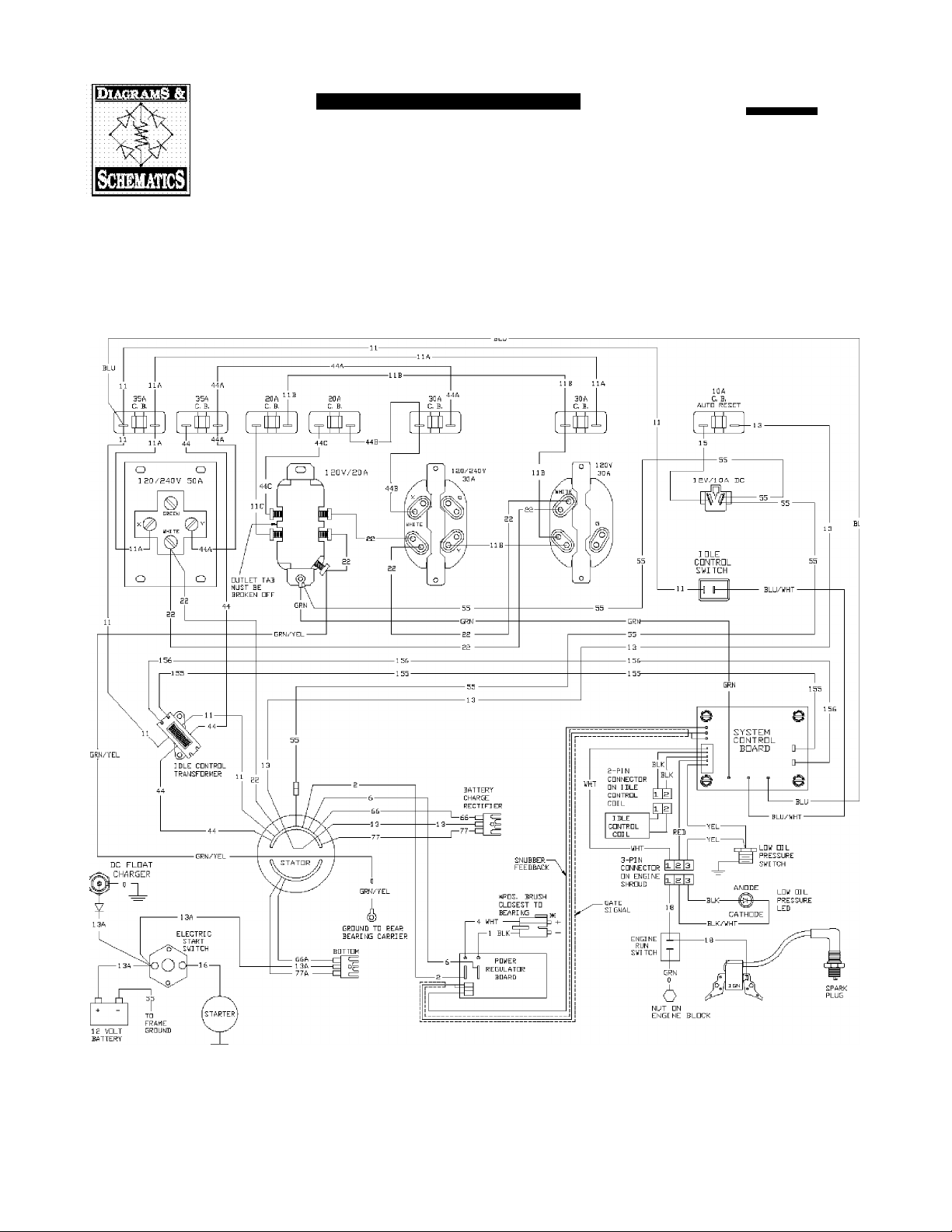
WIRING DIAGRAM
7500EXL Extended Life Generator
Id=lw^l=l=F±T-y
Porteble rrodech
Page 18
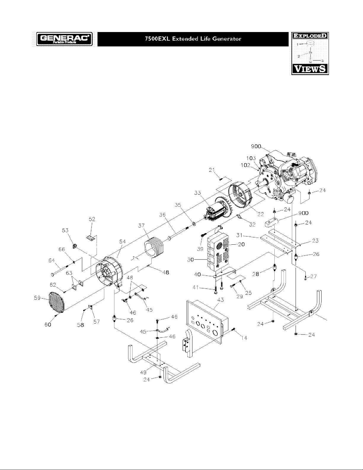
EXPLODED VIEW »ALTERNATOR
Page 19

EXPLODEDVIEW» FRAME
Page 20

PARTS LIST »ALTERNATOR & FRAME
Item Part #
1
BI87024GS
2
I94389GS
3 92982GS
4
9266SGS
5 I93823GS
6 B4363GS
7 83000GS
8 93826GS DECAL, Start Instructions 66 22097GS
9 78831BGS SCREW
10 83463GS
11
7739SGS
12
I92980GS
14
B2I53GS SCREW 80 I88989GS
15 431I6GS SCREW 81 22287GS SCREW
17 73034GS
18 22I27GS
19 778I6GS
20 83083GS
21
86307GS SCREW 86 I89302CGS ASSYWire
22
92247GS
23 M9253IGS
24
I89I60GS
25 22I29GS
26 828S7GS
27 2233IGS SCREW 99 B4I35GS
28 92609GS
29 22I42GS SCREW 101 22I29GS
30 A7433GS
31 B9273IGS
32
90239GS
33 BI342GS
35 96796GS
36 4748IGS SCREW BB306IGS
37 BI897AGS
39 40976GS SCREW 72347GS
40 92332GS
41
66476GS SCREW 7311 IGS
43 B4366GS
44
I94390GS
45 1433362IGS
46 I93646GS
48 8I9I7GS PIN,Rol B4I77GS
49 B4986GS
51 36893GS SCREW 37806GS PLUG, 120V, 30A
32
S4I32GS
S3 67022GS
34
SRV66823DGS
36 23762GS
Description
CRADLE
SHIELD, Heat, Tank
DECAL, Dan;^r
INSULATION
ASSY,Tank, Fuel 62
CAP, with Gauge, Fuel
CLIP, Insulation 64
GROMMET,Tank
NUT, Lock
KIT, Valve Tank
DECAL, Fuel Shut-Off
NUT
DECAL, Hot Muffler 84
SCREEN, Spark Arrestor
HOUSING, Engine Adapter
SUPPORT, Engine
NUT
WASHER, Lock
MOUNXVibration
MOUNXVibration
MUFFLER 102
SUPPORT, Engine & Muffler
GASKET, Muffler
ASSY, Rotor
WASHER
ASSY, Stator
BRACKET, Muffler
ASSY, Contra Panel (see page 21)
SHIELD, Heat
WIRE, Ground
KIT, Grounding Hardware
DECAL, Ground
ASSY, Power Regulator
GROMMET, Rubber
CARRIER, Rear Bearing
WASHER
Item Part#
57 66386GS
58 66849GS SCREW
59 B487IGS
60 74908GS SCREW
63 65795GS
74
77 I89302BGS ASSYWire
78 77282GS
79 I88987GS
82
83 96II3GS ASSYWire
85 B4489GS
87 I85939HGS ASSYWire
88 I93347GS
90 38359GS LUG
97 BI93200GS
98 I897I8GS GRIP
100 22259GS
103 22I25GS
900 NSP
Parts Not Illustrated
Optional Accessories Not Included;
66849CGS SCREW
66449LGS
I94034GS KIT, Fold Down Handle Hardware
22097GS
I92985GS
498I3GS
B4767GS COVER, Storage
I897I3GS
84882GS
43438GS
70I85GS FILTER, Oi
A8927GS
65787GS
I94033GS
84883GS
Description
ASSY, Brush Ho der
COVER, Bearing Carrier
RECTIFIER, Battery Charge
BOLT, Stator
WASHER, Lock
SWITCH, Starter
BRACKET, Switch
ASSY, Jack, DC
WASHER, Lock
TRAY, Battery
BATTERY
KIT, Battery Hardware
ASSY, Handle with Grip
PIN, with L:an^rd
NUT
WASHER, Lock
NUT
WASHER, Lock
ENGINE
BOTTLE, Oil
PLUG, Spark
MANUAL, Owner's
FILTER, Air
WRENCH, Spark P ug
PLUG, l20/240V,30A,4p
MANUAL, Engine
CHARGER, Battery Float
CABLE, Battery Chartge
KIT, Decals
Cord Wrap
Page 21
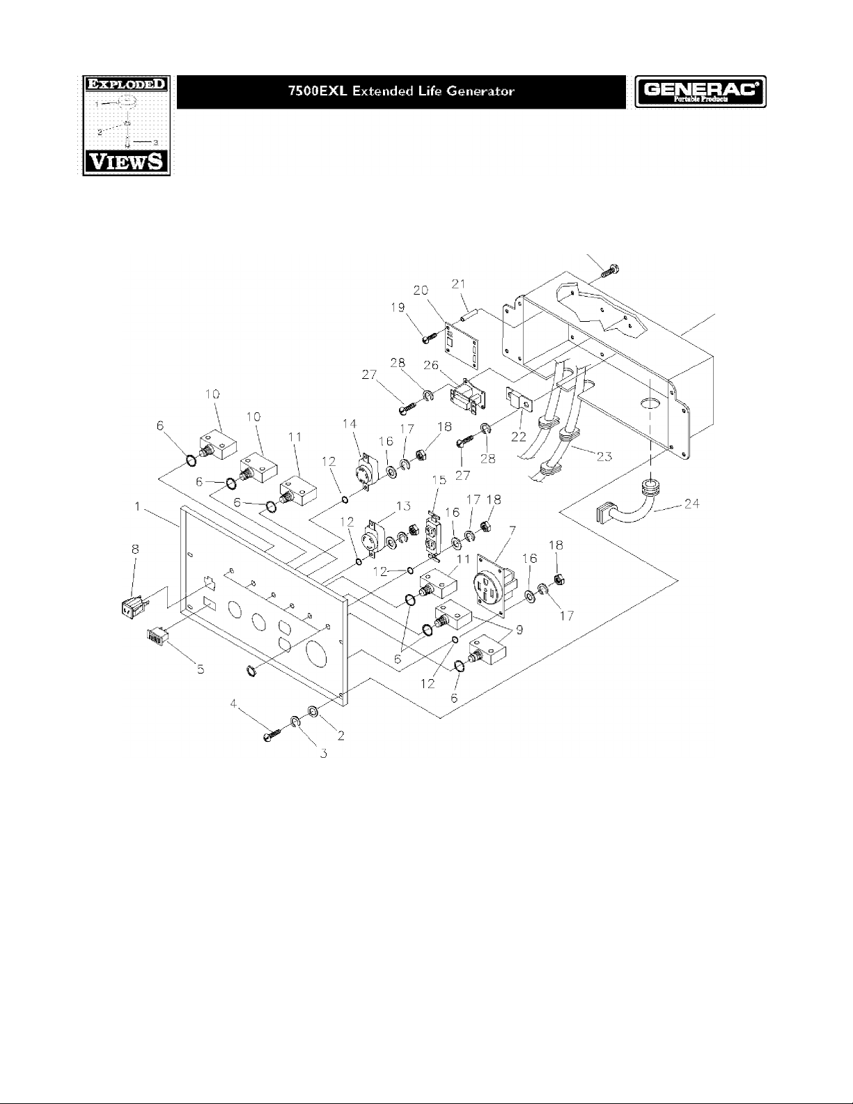
EXPLODED VIEW AND PARTS LIST - CONTROL PANEL
19
25
Item
Part #
1
BB446IGS
2
23897GS
3 49226GS
4
9I526GS SCREW 18 5I7I5GS
3 82538GS
6 8288IGS
7 B4262GS
8 904I8GS
9 75207NGS
ID 75207AGS
1 1
75207GS
12
23365GS
13 68868GS
14
43437GS
Description Item
PANEL, Control
WASHER
WASHER, Lock;
SWITCH, Idle Contro
WASHER, Lock;
OUTLET, 50A, 240V 21
OUTLET, lOA, I2VDC 22
BREAKER, Circuit
BREAKER, Circuit
BREAKER, Circuit
WASHER
OUTLET, 30A, 120V Locking
OUTLET, 30A, 120V/240V Locking
Part #
15 68759GS
16 43i80GS
17 22264GS
19 64526GS SCREW
20 83970GS
64525GS
87962GS BREAKER, Circuit, lOA (auto), 12V
23 84335GS ASSY,Wire Harness
24
84i34GS
25 B92069GS
26 84028GS
27 43I8IGS SCREW
28 43i82GS
Description
OUTLET, 20A, i20V
WASHER
WASHER, Lock
NUT
BOARD, System Controi
STANDOFF, Hex
GROMMET, Rubber Connector
BOX, Control Panel
TRANSFORMER, Id e Control
WASHER, Lock
Page 22

EXPLODED VIEW AND PARTS LIST-WHEEL KIT
15-
Item Part#
I
BI93200GS
1
B4966GS
3
I9I267GGS
4
I9I265GS
3
39287GS
6
BI86927GS
7
I9I4I3GS
8
224I3GS
9
52858GS
ID
22247GS
I I
39253GS
12
22I45GS
13
49820GS
14
I87I04GS
15
I897I8GS
16
B4I35GS
17
I92432GS
Description
HANDLE (Includes Item 15)
WHEEL
AXLE
E-RING
SCREW
LEG, Support
VIBE MOUNT, with Washer
SCREW
NUT, Lock;
WASHER
SCREW
WASHER
NUT, Nylok;
WASHER, Nylon
GRIP
PIN,with Lanyard
NUT, Lock;
Page 23

NOTES
Page 24

G EN ERAC PORTABLE PRODUCTS OWN ER WARRANTY POLICY Eff^ctiw January 1,2003
LIMITED WARRANTY
"Generac Portable Products is a licensed trademark of Brig^ it Stratton Power Products. Briggs & Stratton Power Products win
repair or replace, free of charge, any part, or parts of the eOM'P'^ont^ that are defective in materia!or workmanship or both,
Transporation;charges on; parts ;stibmitted; for repair; or replacement under; this; warranty;must;be; borne by purchaser:Tfiis
warranty is effective for the; time perlods and; subject; to; the conditions provided for; in this policy; For vtarranty service, find your
nearest Authorized seiwice dealer by calling I -SOO-270-14GS, Warranty service may only be ferformed by a Briggs & Stratton
Power Products Authorized service dealer:
TH ERE IS NO OTHER EXPRESS WARRANTY, IMPHEGi WARRANTIES^ INGEUDING THOSE OF MERCHANTABILITY AND
FITNESS FOR A PARTICULAR PURPOSE,ARE LI MIXED TO THE TIME PERIOD SPECIFIED, OR TO THE EXTENT PERMITTED
BY LAWANY ANDALi lMPLIEDWARRANTIES ARE EXCLUDED. LIABILITY FDR CONSEfXJENTIAL DAMAGES UNDER
ANY AND ALL WARRANTIES ARE EXCLUDED TO Tl IE EXTENT EXCLUSION IS PERMITTED BY LAW. Some countr ies or
states do not allow imitat’ons o- how ong an implied warranty lasts, errd some countries or states do not allow tire exclusion
or limitation of ihddeh&i or consequential; darTiageSiisoithe iaboveilirriitaticai; and; exeiusion ;may; hot;E^ply; to; you.This Vrarranly;;;;
gives ;ybu; specific; legal; rights; and; you may also ;have; other; rig^u that vary fixan; cbu;ntry; to; country ;ar; state ;to; state.”;;;;;;;;;;;;;;;;
WARRANTY PERIOD*
Equipment **
Pressure-Washer..................................................
Portab e Generator 2Yea.rs (2nd year parts only)
* The warranty period begins on tne date of purciiase by tire first retail consumer Or cornmercia end User, and corttinues for the
period of time stated in the table above. "Consumer use" means personal residentia household use by a retail consumer,
^Commercial use" means all other uses, including use for commeixial, income producing or rental purposes. Once equipment has
been; used commercially, it shall thereafter ;be; considered to ;be; In commercial ; use for; purposes ;of this ;warranqr.
^The; engine and starting; batteries areilwsrrantsd solely by the manufacturers; of those; products. ;;;;;;;
WARRANTY REGISTRATION IS NOT NECESSARY TO OBTAIN WARRANTY ON BRIGGS & STRATTON
POWER PRODUCTS EQUIPMENT SAVE YOUR PROOF OF PURCHASE RECEIPT IF YOU DO NOT PROVIDE
PROOF OF THE INITIAL PURCHASE 13ÄTEÄT THE TIME VVARRANTY SEFtVlCE IS REQUESTEDi.THE
MANUFACTURING PATE OF THE EQUIPMENT WILL BE US ED TO DET ERMINE THE WARRANTY PERIOD.
About your;equipment warrantys; ;;;;;;;;;;;;;;;;;;;;;;;;;;;;;;;;;;;;;;;;;;;;;;;;;;;;;;;;;;;;;;;;;;;;;;;;;;;;;;;;;;;;;;;;;;;
We; welcome warrant repair;and apologize;to; you; for ;being; inconvenienced.;Any Authorized;ser¥ice;d^ler may perform warranty
repairs, Most ;vrarranty; lepairs are; handled; routinely but sometimes; requests for; warranty ;service rnay not be appropriate. For
example, ;warranty; service; would ; not lapplyiif lequiprnent Idamage; occurred I because; Of;rniSüse,; lack of ;routine maintenance, shipping,
handling, Warehciustnglor improper' instailaticin,;SirTÌi[arty,;the; warraniy; is! void! if Ithe Imäntifactüririg date dr Ithel serial Inumber Ion thel
equifjrnent; has ;been Iremdvedlòr: the; equipment; has ;b®d^; ^Ifd^eid; pf Imddified. Düring; the Ivrarräniy; f5eriod,;the Authorized; service! I
deafer,;at ;its;pptionj;w||l; ;repatr;pr replace iany; part; that, upon; examination;,;is;found; to; be defective; under normal use and; service.
This; warrantyiv^ll mot cover following: impairs land; equipment: ;;;;;;;;;;;;;;;;;;;;;;;;;;;;;;;;;;;;;;;;;;;;;;;;;;;;;;;;;;;;;;;;;;;;;;;;;;;;;;;;;;;;
* ; ; ; Normal; Weiar;; Outdoor; power; equipment; ;like; all; mechanical ideyices, needs iperiodic; parts,;serytce ;and ; replacement to
; ; ; ; ;perfprm: welL This I warranty ;does; ;not cover repair when; normal; use; has ;6xhausied:the ;l;ife of a part or; the; equipment.
* ; ; ;|nstid;tation ;and ;Maiutenifoc6i This; warraniy id Udt apply ;fo ;equiprhent ;or;partSI tbat;hayei been;subjected; to improper or;
; ; ; ; ;unauthorized: Installation: or ;alterati:Oh; and; rhodiflicatidni mtsusei negligehcei aceidenL overloading,;overspeeding,; im:proper; ;
.................
..........................
Cònsiihriér :Usiè................
1-Year
........................
....
.................
..........................
............................
Commercial Use
90 Days
..........................
|: Year...........................
...
1111 imaihtenancei,irepair or istoragei so; aSiiiini our; judgmenLitoiadverseiyiaffect litsipefformanceiimdi reliability This warranty; also :does:
; ; ; ; InOfmai Imaintehance: such las adjustmehtsufoel Isystern Icleahtnglaind Idbstraicttcnl (due ltd Ichemical, dirt,!carbon :or: lime: I
; ; ; ; ;etc.). ; ; ; ; ; ; ; ; ; ; ; ; ; ; ; ; ; ; ; ; ; ; ; ; ; ; ; ; ; ; ; ; ; ; ; ; ; ; ; ; ; ; ; ; ; ; ; ; ; ; ; ; ; ; ; ; ; ; ; ; ; ; ; ; ; ; ; ; ; ; m
* : : lOther lExciUsidns; Also lexclUdedl frornlthislwafralniy lare! wear iternslsuchl as! cjütcklcdüplerä. Oil l^u;^s, belts, lol-rings,Titers,
; ; ; ; pump ;piacklng,;etc:, pumps which lhave; been;run ;wlth0üt;viäter;supplied ;or;damage or;malfunctions Iresulting from accidents,
abuse, modifications, aerations, or improper servicing or freecingor chemical deterioration, Accessory parts such as guns,
; ; ; ; ;hoses, wands;and; nozzles ;are;exc|uded from ;the; product; vrarranty.Also; excluded ;ts;used,;reconditioned, and demonstration
; ; ; ; ;equipment;;equipment;used ;for ;prime;power; in ;place;of;ut{lity ;power;and ;equipmeht;used; iu; life;support applications.
..................................................
BRIGGS & STRATTON POWER PRODUCTS GROUP, LLC
JEFFERSON, WISCONSIN, U.S.A,
 Loading...