

Page 1

0F9765MNL
3.0 liter
G A S
P.O. BOX 310 EAGLE WI 53119
Ford
Duratec
ENGINE
PARTS
MANUAL
PRINTED IN U.S.A.
Revision 0: 09/12/06
Page 2

3.0L GAS ENGINE TABLE OF CONTENTS
QUICK REFERENCE GUIDE ................................................................................................................................... 1
SERVICE RECOMMENDATIONS ............................................................................................................................2
CYLINDER BLOCK & RELATED PARTS ................................................................................................................. 6
CYLINDER BLOCK & RELATED PARTS ................................................................................................................. 7
CYLINDER HEAD & RELATED PARTS ...................................................................................................................8
CYLINDER HEAD & RELATED PARTS ...................................................................................................................9
PISTON & CONNECTING ROD ............................................................................................................................. 10
TIMING COMPONENTS ........................................................................................................................................ 11
CRANKSHAFT & RELATED PARTS ...................................................................................................................... 12
CRANKSHAFT & RELATED PARTS ...................................................................................................................... 13
ENGINE COMMON PARTS ....................................................................................................................................14
LEGEND
“ A R ” A S R E Q U I R E D
“ S T D ” S TA N D A R D S I Z E
“ O. S .” O V E R S I Z E
“ U . S .” U N D E R S I Z E
“ N A ” N O T AVA I L A B L E
NOTICE!
THE INFORMATION IN THIS MANUAL IS KNOWN TO BE ACCURATE AS OF THE DATE OF
RELEASE SHOWN ON THE COVER. HOWEVER, ENGINEERING CHANGES CAN OCCUR
WITHOUT NOTICE. TO OBTAIN THE PROPER PARTS, PLEASE BE SURE TO USE THE
MODEL NUMBER OF THE UNIT BEING SERVICED WHEN ORDERING FROM THIS MANUAL.
Page 3
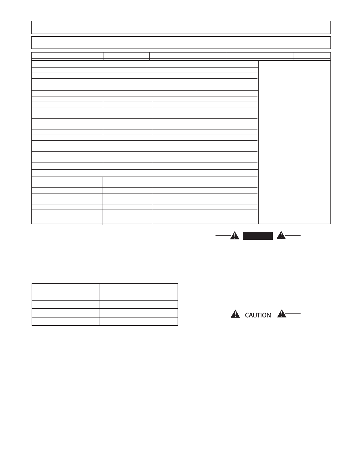
3.0L GAS ENGINE QUICK REFERENCE GUIDE
DANGER
QUICK REFERENCE ENGINE PARTS
ENGINE SIZE: 3.0 Liter FUEL: Gas MAKE: Ford ENGINE P/N: 0F9765 MODEL: —
OIL CAPACITY: 1.0 gallons (w/filter) COOLANT CAPACITY: 4.0 gallons
scheduled maintenance kits
Description Part Number
Oil/Air NA
– –
common reference parts
Description Part Number Special Notes
Oil Filter (Main) 0D5419
Fuel Filter NA
Air Cleaner Element Check BOM
V-Belt 0D3488N Serpentine
Thermostat 075885
Thermostat Gasket 048665
Water Pump 0F9225
Starter Motor 0E9747
Spark Plug 0F97650226
additional reference parts
Alternator 0E9868A
Ignition Coil 0F9228
User Notes
◆ Engine Oil Recommendations
The unit has been filled with “break in” engine oil
at the factory. Use a high-quality detergent oil classified “For Service CC, SD, SE or SF.” Detergent oils keep
the engine cleaner and reduce carbon deposits. Use oil
having the following SAE viscosity rating, based on the
ambient temperature range anticipated before the next
oil change:
Temperature Oil Grade (Recommended)
Above 75º F (24º C) SAE 30W
40º to 75º F (4.4º to 24º C) SAE 20W or 15W-40
10º to 40º F (-12º to 4.4º C) SAE 10W or 15W-40
Below 10º F (-12º C) SAE 5W-30 (Synthetic) or 5W-20
◆ Coolant
Use a mixture of half low silicate, ethylene glycol base
antifreeze and half soft water. Use only soft water and
only low silicate antifreeze. If desired, you may add a
high quality rust inhibitor to the recommended coolant
mixture. When adding coolant, always add the recommended 50-50 mixture.
Do not remove the radiator pressure cap while
the engine is hot or serious burns from boiling
*
liquid or steam could result.
Ethylene glycol base antifreeze is poisonous.
Do not use your mouth to siphon coolant from
*
the radiator, recovery bottle or any container.
Wash your hands thoroughly after handling.
Never store used antifreeze in an open container
because animals are attracted to the smell and
taste of antifreeze even though it is poisonous to
them.
Do not use any chromate base rust inhibitor with
*
ethylene glycol base antifreeze, or chromium
hydroxide (“green slime”) will form and cause
overheating. Engines that have been operated
with a chromate base rust inhibitor must be
chemically cleaned before adding ethylene glycol
base antifreeze. Using any high silicate antifreeze boosters or additives also will cause overheating. We also recommend that you DO NOT
use any soluble oil inhibitor for this equipment.
1
Page 4

3.0L GAS ENGINE SERVICE RECOMMENDATIONS
8 kW - 35 kW Small Standby Generator Sets
Following is a recommended maintenance schedule for Generac small standby and residential generator sets
from 8 kW to 35 kW in size, and applies to both diesel engine and gas engine driven units. The established
intervals in the schedule are the maximum recommended when the unit is used in an average service application. They will need to be decreased (performed more frequently) if the unit is used in a severe application.
Use the unit hour meter or calendar time, whichever occurs first, from the previous maintenance interval to
determine the next required maintenance interval.
Service Maintenance Interval Information:
The various service maintenance intervals are designated by interval numbers as follows:
1 An early inspection of the generator set to insure it is ready to operate when required and to identify any
potential problem areas.
Performed monthly or following each 10 hours of operation of the unit and requires approximately .5
man-hours per unit to complete.
This inspection may be performed by the end user providing the following safety steps are taken to pre-
vent the engine from starting automatically without warning:
To prevent injury, perform the following steps in the order indicated before starting any maintenance:
• Disable the generator set from starting and/or connecting to the load by setting the control panel
Auto-Off-Manual switch to the “OFF” position.
• Remove the control panel fuse.
• Turn off the battery charger.
• Remove the negative battery cable.
The battery charger must be turned off BEFORE removing the battery cable to prevent an over current con-
dition from burning out sensitive control panel components and circuits.
*
Following all maintenance, reverse these steps to insure the unit is returned to standby setup for normal
operation when required.
2 A break-in service inspection of the generator set to insure it is ready to operate and carry the load when
required, and to identify any potential problem areas.
Performed ONLY ONCE following the first three months or the first 30 hours of operation after purchase
of the unit and requires approximately 2.5 man-hours per unit to complete.
This inspection contains some maintenance tasks which require special tools, equipment, and/or knowl-
edge to accomplish and should be performed only by an authorized Generac Service Dealer.
3 An operational inspection of the generator set to insure it is ready to operate and carry the load when
required, and to identify any potential problem areas.
Performed semi-annually or following each 50 hours of operation of the unit and requires approximately
1.5 man-hours per unit to complete.
This inspection contains some maintenance tasks which require special tools, equipment, and/or knowl-
edge to accomplish and should be performed only by an authorized Generac Service Dealer.
4 A mid-level inspection of the generator set to insure it is ready to operate and carry the load when required,
and to identify any potential problem areas.
Performed annually or following each 100 hours of operation of the unit and requires approximately 4.0
man-hours per unit to complete.
This inspection contains some maintenance tasks which require special tools, equipment, and/or knowl-
edge to accomplish and should be performed only by an authorized Generac Service Dealer.
2
Page 5
!
!
3.0L GAS ENGINE SERVICE RECOMMENDATIONS
GENERAC POWER SYSTEMS, INC.
RECOMMENDED SCHEDULED MAINTENANCE PROGRAM
SERVICE WORK TO BE PERFORMED BY FACTORY-TRAINED PERSONNEL ONLY.
DEALER INFORMATION
NAME: ____________________________________
ACCOUNT #: _______________________________
ADDRESS: _________________________________
PHONE: ___________________________________
TECHNICIAN: ______________________________
SIGNATURE: _______________________________
PURCHASE DATE: ____________________ START-UP DATE: ____________________
APPLICATION: ____ Standby Power ____ Prime Power ____ Rental/Trailerized
NAME: ____________________________________
ADDRESS: _________________________________
SITE: _____________________________________
PHONE: ___________________________________
SIGNATURE: _______________________________
OWNER INFORMATION
GENERATOR & TRANSFER SWITCH INFORMATION
GENERATOR
MODEL NUMBER:___________________________
SERIAL NUMBER:___________________________
MODEL NUMBER:___________________________
SERIAL NUMBER:___________________________
TRANSFER SWITCH
HOUR METER READING at Completion of the Inspection:___________________________
WARNING!
To prevent injury, perform the following steps in the order indicated before starting any maintenance:
• Disable the generator set from starting and/or connecting to the load by setting the control panel
Auto-Off-Manual switch to the “OFF” position.
• Remove the control panel fuse.
• Turn off the battery charger.
• Remove the negative battery cable.
NOTE:
The battery charger must be turned off BEFORE removing the battery cable to prevent an over current
condition from burning out sensitive control panel components and circuits.
Following all maintenance, reverse these steps to insure the unit is returned to standby setup for normal
operation when required.
3
Page 6
3.0L GAS ENGINE SERVICE RECOMMENDATIONS
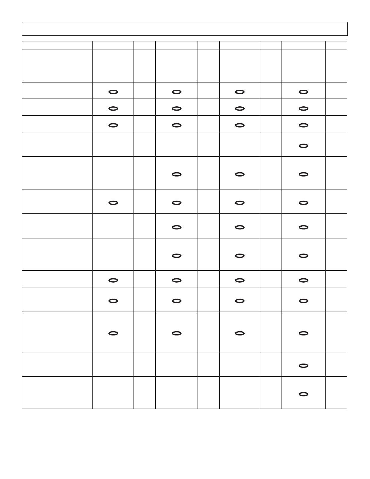
Maintenance Tasks Level 1 Level 2 Level 3 Level 4
1. Disable the unit from operating
per the first page warning.
2. Check the engine oil level. Adjust
as necessary.
3. Check the engine coolant level.
Adjust as necessary.
4. Check the engine coolant ther-
mal protection level. Correct as
necessary.
5. Check the natural gas delivery
system on gas engine driven
units. Tighten connections as
necessary.
6. Check the diesel fuel supply
level for diesel engine driven
units. Fill as necessary.
7. Drain water and sediment from
the diesel fuel tank on diesel
engine driven units.
8. Drain water from the fuel line
water separator on diesel
engine driven units if the unit is
equipped with one.
9. Check the air inlets and outlets
for debris. Clean as necessary.
10. Check the battery electrolyte
level if accessible. Adjust as
necessary.
11. Check the battery posts,
cables, and charger for loose
connections, corrosion, and
proper operation. Correct as
necessary.
12. Check the unit wiring for loose
connections, corrosion, and
damage. Correct as necessary.
13. Check the engine accessory
drive belts for wear, weather
cracking, and damage. Replace
as necessary.
Recommended to
be done monthly/
10 hrs.
Task
Comp.
(Date-
Initials)
Required to be
done 3 months/
Break-in /30 hrs.
• • • •
• • • •
• • • •
• • •
• • • •
• • •
• • •
• • • •
• • • •
• • • •
Task
Comp.
(Date-
Initials)
Required to
be done Semi-
Annually/50 hrs.
Task
Comp.
(Date-
Initials)
Required to be done
Annually/ 100 hrs.
•
•
•
Task
Comp.
(Date-
Initials)
4
Page 7

3.0L GAS ENGINE SERVICE RECOMMENDATIONS
Maintenance Tasks Level 1 Level 2 Level 3 Level 4
14. Visually inspect the unit look-
ing for leaks, wear or damage,
loose connections or compo-
nents, and corrosion. Correct
as necessary.
15. Test the engine and transfer
switch safety devices. Correct
and/or adjust as necessary.
16. Initiate an automatic start and
transfer of the unit to site load
and exercise it for at least 1
hour looking for leaks, loose
connections or components,
and abnormal operating condi-
tions. Correct as necessary.
17. Start and exercise the unit at
full rated load (use a load bank
if the site load is not enough)
for at least 2 hours looking
for leaks, loose connections
or components, and abnormal
operating conditions. Correct as
necessary.
Recommended to
be done monthly/
10 hrs.
Task
Comp.
(Date-
Initials)
Required to be
done 3 months/
Break-in /30 hrs.
• • • •
• •
Task
Comp.
(Date-
Initials)
Required to
be done Semi-
Annually/50 hrs.
Task
Comp.
(Date-
Initials)
Required to be done
Annually/ 100 hrs.
•
•
Task
Comp.
(Date-
Initials)
18. Change the engine oil.
19. Replace the engine oil filter(s).
20. Replace the engine air filter(s).
21. Replace the engine fuel filter(s)
on diesel engine driven units
and re-prime the fuel system.
22. Check the engine spark plugs
on gas engine driven units.
Clean and re-gap orreplace as
necessary.
23. Perform a 5 minute no-load
operational run of the unit
looking for any post service
problems.
24. Return the unit to standby
setup for operation when
required.
•
• •
• •
• •
• •
• •
• • • •
5
Page 8
3.0L GAS ENGINE CYLINDER BLOCK & RELATED PARTS
6
Page 9

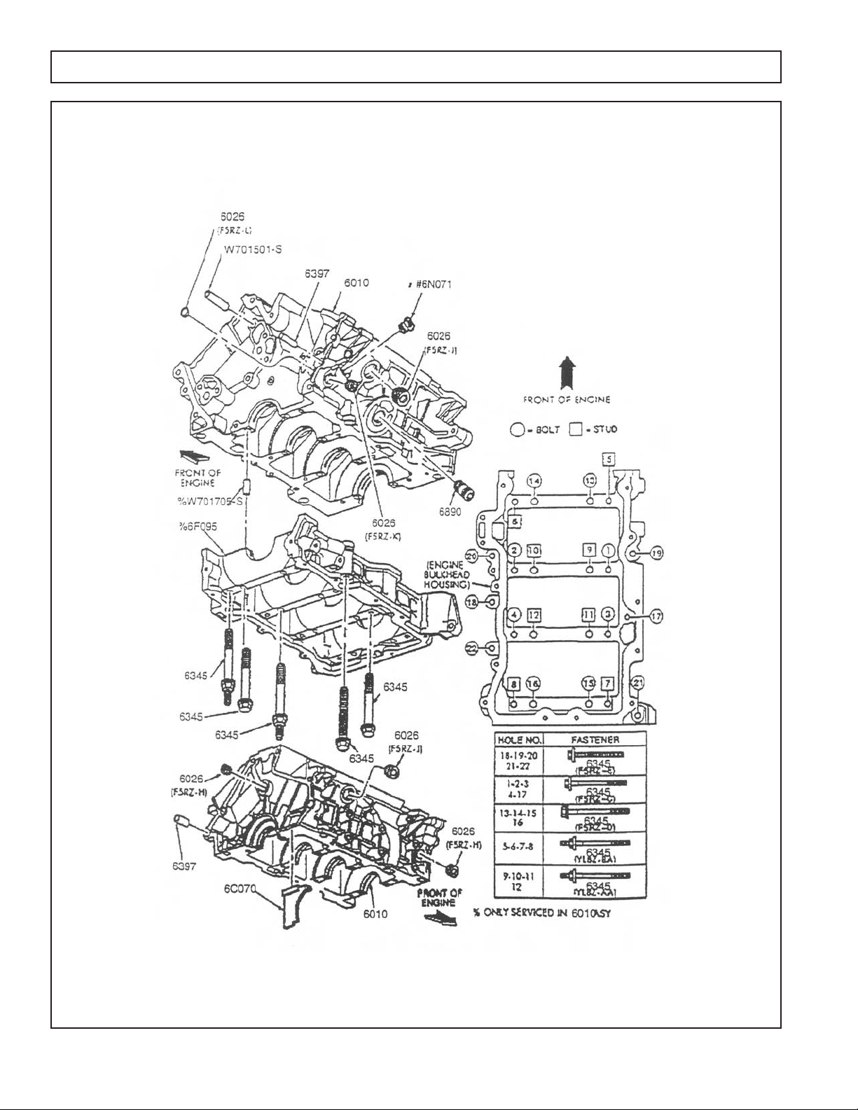
3.0L GAS ENGINE CYLINDER BLOCK & RELATED PARTS
ITEM PART NUMBER DESCRIPTION QTY
ENGINE BLOCK
0F9765 SHORT BLOCK 1
REMAN ENGINE ASSY 1
6890 0F97650100 OILFILTER MOUNTING INSERT 1
W701501 0F97650101 DOWEL, TIMING CHAIN GUIDE 1
TIMING COVER
6019 0F97650102 FRONT TIMING COVER 1
6020 0F97650103 TIMING COVER GASKET, RH 1
6020 0F97650104 TIMING COVER GASKET, CENTER 1
6020 0F97650105 TIMING COVER GASKET, LH 1
6700 0F97650106 TIMING COVER SEAL 1
W701525 0F97650107 BOLT,M8 X 51MM POS.4,10,13,14,15 & 16 6
W701240 0F97650108 BOLT, M8 X 34MM POS.7 & 9 2
W701581 0F97650109 STUD M8 X 68MM X M8 X 2MM POS.2,3,5,6,8,11, &12 7
W701712 0F97650110 STUD M6 X 20 M8 X 47.5 POS. 1 1
W701228 0F97650111 DOWEL TIMING COVER TO BLOCK 2
PLUGS-CYLINDER BLOCK
6026 0F97650112 1/2" X 14 MM PIPE, RG & CENTER REAR OF BLOCK 2
6026 0F97650113 3/4" X 14MM PIPE RH & LH SIDE OF BLOCK 2
6026 0F97650114 3/8" X 18MM PIPE LH SIDE OF BLOCK 1
6026 0F97650115 19.35MM CUP LH SIDE OF BLOCK 1
6026 0F97650116 1 X 11.5MM PIPE RH & LH CYLINDER HEAD 2
6026 0F97650117 1/4" X 18 MM PIPE RH & LH CYLINDER HEAD 9
6391 0F97650118 DOWEL TRANY TO BLOCK 2
OIL PRESSURE SENDING UNIT
9278 0F97650119 OIL PRESSURE SENDING UNIT 1
6N071 0F97650120 OIL PRESSURE SENDING UNIT TO BLOCK ADAPTER 1
MAIN BOLTS
6345 0F97650121 HOLE # 1,2,3,4 &17 5
6345 0F97650122 HOLE # 13,14,15,& 16 4
6345 0F97650123 HOLE # 18,19,20,21,& 22 5
6345 0F97650124 HOLE #9,10,11 & 12 4
6345 0F97650125 HOLE #5,6,7,& 8 4
7
Page 10

3.0L GAS ENGINE CYLINDER HEAD & RELATED PARTS
8
Page 11

3.0L GAS ENGINE CYLINDER HEAD & RELATED PARTS
ITEM PART NUMBER DESCRIPTION QTY
CYLINDER HEAD ASSEMBLY
6049 0F97650126 CYL., HEAD, COMPLETE WITH VALVES, LESS CAMS 1
6049 0F97650127 CYL., HEAD, COMPLETE WITH VALVES, LESS CAMS 1
6051 0F97650128 HEAD GASKET, LH 1
6051 0F97650129 HEAD GASKET, RH 1
6065 0F97650130 HEAD BOLT,M10 X 156MM, PKG OF 8 16
VALVES
6505 0F97650131 EXHAUST VALVE, STANDARD 6
6507 0F97650132 INTAKE VALVE, STANDARD 6
6571 0F97650133 VALVE STEM SEAL, INTAKE 6
VALVE TRAIN
6513 0F97650134 VALVE SPRING 6
6514 0F97650135 VALVE SPRING RETAINER 12
6518 0F97650136 VALVE SPRING LOCK KEY 24
6564 0F97650137 ROCKER ARM 24
6C501 0F97650138 LASH ADJUSTER 24
6L293 0F97650139 CAMSHAFT BEARING CAP BOLT (NOT REPLACED 11-97) A/R
CAMSHAFT
6250 0F97650140 CAMSHAFT, RH INTAKE 1
6250 0F97650141 CAMSHAFT, LH INTAKE 1
6250 0F97650142 CAMSHAFT, RH EXHAUST 1
6250 0F97650143 CAMSHAFT, LH EXHAUST 1
6L253 0F97650144 ARM, TINING CHAIN TENSIONER 2
OIL FILLER / BREATHER / PCV VALVE
6A785 0F97650145 OIL SEPERATOR ASSEMBLY 1
W701504 0F97650146 BOLT, OIL SEPERATOR 1
6A664 0G0607 CRANKCASE ASPIRATOR HOSE ASSEMBLY 1
6762 0F97650147 ELBOW 1
6A666 0F97650148 PCV VALVE 1
9
Page 12

3.0L GAS ENGINE PISTON & CONNECTING ROD
ITEM PART NUMBER DESCRIPTION QTY
PISTON & PIN ASSEMBLY
6100 0F97650149 PISTON, PIN, RINGS & CONNECTING ROD, STANDARD 6
6148 0F97650150 RINGSET, STANDARD 3
CONNECTING ROD
6200 0F97650151 CONECTING ROD 6
6135 0F97650152 PISTON PIN 6
6207 0F97650153 BUSHING, PISTON PIN 6
6140 0F97650154 PISTON PIN RETAINING CLIP 12
6214 0F97650155 BOLT, ROD 12
ROD BEARINGS
(SOLD IN PACKS OF TWO HALVES)
6211 0F97650156 ROD BEARING,STANDARD, UPPER & LOWER 12
10
Page 13

3.0L GAS ENGINE TIMING COMPONENTS
ITEM PART NUMBER DESCRIPTION QTY
6268 0F97650157 TIMING CHAIN, RH OR LH 2
6L253 0F97650158 TENSIONER ARM, RH OR LH 2
6K297 0F97650159 TIMING CHAIN GUIDE, RH 1
6K297 0F97650160 TIMING CHAIN GUIDE, LH 1
6L266 0F97650161 TIMING CHAIN TENSIONER, RH OR LH 2
W701524 0F97650162 BOLT TENSIONER 4
W701232 0F97650163 BOLT, TENSIONER ARM 6
6306 0F97650164 CRANKSHAFT SPROCKET, TWO ROW 1
11
Page 14

3.0L GAS ENGINE CRANKSHAFT & RELATED PARTS
12
Page 15

3.0L GAS ENGINE CRANKSHAFT & RELATED PARTS
ITEM PART NUMBER DESCRIPTION QTY
CRANKSHAFT ASSEMBLY
6303 0F97650165 CRANKSHAFT 1
6B316 0F97650166 CRANKSHAFT KEY 1
12A227 0F97650167 PULSATOR RING, CRANKSHAFT SENSOR 1
6C315 0F97650168 CRANKSHAFT TIMING SENSOR 1
12257 0F97650169 BRACKET, IGNITION MOUNTING 1
18801 0F97650170 CAPACITOR 1
CRANKSHAFT PULLEY
6316 0F97650171 CRANKSHAFT DAMPER 1
6A340 0F97650172 BOLT, CRANKSHAFT DAMPER 1
6378 0F97650173 WASHER, PULLEY TO CRANKSHAFT 1
6A312 0F97650174 PULLEY, CRANKSHAFT 1
CRANKSHAFT MAIN BEARING KITS
6D309 0F97650175 MAIN BEARING KIT, STANDARD 1
6D309 0F97650176 MAIN BEARING KIT, .010" UNDERSIZE(25MM) 1
6D309 0F97650177 MAIN BEARING KIT, .020" UNDERSIZE (50MM) 1
13
Page 16

3.0L GAS ENGINE OIL PUMP, OIL PAN & RELATED PARTS
14
Page 17

3.0L GAS ENGINE OIL PUMP, OIL PAN & RELATED PARTS
ITEM PART NUMBER DESCRIPTION QTY
OIL PUMP
6600 0F97650178 OIL PUMP ASSEMBLY 1
W500300 0F97650179 BOLT,PUMP TO BLOCK 4
W700005 0F97650180 BOLT, PICK UP TO PUMP 2
6622 0F97650181 OIL PUMP PICK UP TUBE & SCREEN 1
6626B 0F97650182 OIL PUMP INLET TUBE GASKET 1
OIL PAN
6675 0F97650183 OIL PAN 1
6687 0F97650184 BAFFLE, OIL PAN 1
W701542 0F97650185 NUT,M6 X 1MM 5
6730 0F97650186 OIL PAN DRAIN PLUG 1
6734 0F97650187 OIL PAN DRAIN PLUG GASKET 1
6710 0F97650188 OIL PAN GASKET 1
W701605 0F97650189 BOLT, OIL PAN A/R
W701606 0F97650190 STUD OIL PAN A/R
6754 0F97650191 DIPSTICK TUBE 1
6750 0F97650192 DIPSTICK 1
W701585 0F97650193 BOLT, TUBE TO BLOCK 1
6C629 0F97650194 OIL PAN SPACER,SELECT FIT,YELLOW (#SILVER) 1
6C629 0F97650195 OIL PAN SPACER,SELECT FIT,BLUE (#GOLD) 1
OIL FILTER
6731 0D5419 OIL FILTER 1
15
Page 18

3.0L GAS ENGINE ROCKER COVER & RELATED PARTS
ITEM PART NUMBER DESCRIPTION QTY
6582 0F97650196 ROCKER COVER, RH 1
6582 0F97650197 ROCKER COVER, LH 1
6584 0F97650198 ROCKER COVER GASKET, RH 1
6584 0F97650199 ROCKER COVER GASKET, LH 1
6C519 0F97650200 STUD & GROMMET 1
6C519 0F97650201 BOLT & GROMMET 1
6766 0F97650202 OIL FILLER CAP 1
16
Page 19

3.0L GAS ENGINE COOLING SYSTEM
ITEM PART NUMBER DESCRIPTION QTY
8501 0F9225 WATER PUMP 1
8A507 0F97650203 WATER PUMP OUTLET CONNECTION 1
8508 0F97650204 COVER WATER PUMP 1
8A505 0F97650205 INLET WATER TUBE 1
8555 0F97650206 WATERTUBE, CROSSOVER 1
6A312 0F97650207 ACCESSORY DRIVE PULLEY 1
8620 0F9562 BELT, WATER PUMP 1
17
Page 20

3.0L GAS ENGINE INTAKE AND EXHAUST MANIFOLD
ITEM PART NUMBER DESCRIPTION QTY
INTAKE MANIFOLD
9424 0F9222 UPPER INTAKE MANIFOLD ASSEMBLY 1
9424 0F9221 LOWER INTAKE MANIFOLD ASSEMBLY 2
9H486 0F9224 GASKETS, UPPER TO LOWER INTAKE MANIFOLD 6
9439 0F9223 GASKETS, LOWER MANIFOLD TO HEAD (PKG OF 6) 2
9E470 0F97650208 TUBE ASSY,EGR VALVE OUTLET 1
W701504 0F97650209 BOLT, EGR TUBE TO UPPER INTAKE MANIFOLD 2
9S479 0F97650210 ISOLATOR ASSY, INTAKE MANIFOLD 1
9F593 0F97650211 INJECTOR 6
9F792 0F97650212 FUEL RAIL 1
9H321 0F97650213 FUEL PRESSURE RELIEF VALVE 1
9H323 0F97650214 FUEL PRESSURE RELIEF VALVE CAP 1
9F972 0F97650215 FUEL INJECTOR SENSOR 1
W500203 0F97650216 SCREW, SENSOR TO RAIL 2
W701572 0F97650217 BOLT,FUEL RAILTO LOWER INTAKE MANIFOLD 4
W708187 0F97650218 BOLT,FUEL RAILTO LOWER INTAKE MANIFOLD 4
EXHAUST MANIFOLD
9448 0G0100 EXHAUST MANIFOLD GASKET 2
9E498 0F97650219 CONNECTOR, EMMISSION VACUMN CNTRL 1
9D476 0F97650220 GASKET EGR VALVE 1
9D477 0F97650221 TUBE , EGR TO EXHAUST MANIFOLD 1
W701732 0F97650222 STUD, EXHAUST MANIFOLD TO HEAD 12
W701706 0F97650223 NUT, EXHAUST MANIFOLD TO HEAD 12
18
Page 21

3.0L GAS ENGINE IGNITION
ITEM PART NUMBER DESCRIPTION QTY
12029 0F9228 COIL 1
18801 0F97650224 IGNITION INTERFERENCE CAPACITOR 1
W701547 0F97650225 BOLT, COIL TO ENG,3/8" 16X.75" 4
0F97650226 SPARK PLUG 6
12259 0F9556 WIRESET, SPARK PLUGS 1
12297 0F97650227 SEPERATOR, IGNITION WIRE 1
12297 0F97650228 SEPERATOR, IGNITION WIRE 1
12A581 0F97650229 ENGINE CONTROL WIRE HARNESS 1
14536 0F97650230 BRACKET, WIRING 1
19
Page 22

G-8403-C
6/21/06
ENGINE COMMON PARTS
0F9766
D
DRAWING #:
EXPLODED VIEW:
REVISION:
DATE:
PAGE 1 OF 3
GROUP
SPECIFIC
AT
I
ON
S
FOR ENGINE
OI
L
OW
N
ERS MANU
AL
REFER
T
O
0
F
5
1
1
4
WIRE
GRD.
85
84
82
83
11
50
24
"B"
25
51
96
32
45
31
102
97
47
46
59
15
62
39
63
98
9
58
43
42
49
64
2
32
45
31
"C"
65
18
44
19
2
66
55
105
32
75
35
73
21
76
53
52
77
76
"TO A"
35
56
100
36
99
20
104
1
61
74
32
17
72
56
LOWER
RADIATOR
HOSE
31
30
8
"TO B"
82
2
42
"A"
27
28
92
87
32
49
90
35
36
91
31
36
68
79
88
80
82
81
82
4
68
79
82
UPPER
RADIATOR
HOSE
70
41
26
2
48
44
14
ROUTED UNDER STATOR
CAN
"TO C"
67
28
35
103
16
12
34
84
83
86
28
94 (GRD. SCREW)
89
43
36
3.0L GAS ENGINE COMMON PARTS
20
Page 23

3.0L GAS ENGINE COMMON PARTS
ITEM PART NUMBER DESCRIPTION QTY
1 0F9765X ENGINE FWD MAKE 1
2 022131 WASHER FLAT 3/8-M10 ZINC 5
4 085662D TIE WRAP UL 17.7 X .35 BLK HT 1
8 0F9258 SUPPORT COOLANT TUBE 1
9 0D5419 (REF.) OIL FILTER 1
11 0F8931 SPACER FLEX PLATE 1
12 027482 WASHER SHAKEPROOF EXT 5/16 STL 1
14 0A6751 SWITCH HI-TEMP 245D X 3/8 NPT 1
15 033472 RIVET POP .125 X .400 AL 6
16 0E9747 STARTER 12 VOLT 1
17 0E6585 COVER IAC ACTUATOR 1
18 0F8425 ADAPTER ENGINE 1
19 0F9965C FLEX PLATE 2 POLE 1
20 055476 BSHG RDCR HEX 3/8 TO 1/8 GALV 1
21 0A8584 SWITCH OIL PRESSURE 10 PSI 2 POL 1
24 083896 WASHER LOCK 1/4-M6 SS 6
25 084929 WASHER FLAT 1/4 SS 6
26 0F3844 WASHER FLAT .45 X 1.00 8
27 077996 CAP ANTIFREEZE RUBBER 1
28 057823 CLAMP HOSE #10 .56-1.06 3
30 047411 SCREW HHC M6-1.0 X 16 G8.8 2
31 022097 WASHER LOCK M6-1/4 8
32 022473 WASHER FLAT 1/4-M6 ZINC 16
34 0G0153 BARBED EL 90 1/2 NPT X 3/4 HOSE 1
35 022129 WASHER LOCK M8-5/16 14
36 022145 WASHER FLAT 5/16-M8 ZINC 14
39 067989 NUT HEX FL WHIZ M8-1.25 12
41 0D5417 SCREW HHC M10-1.0 X 25 G10.9 8
42 046526 WASHER LOCK M10 3
43 049226 WASHER LOCK M5 8
44 064416 SCREW HHC M10-1.5 X 45 G8.8 FT 6
45 043116 SCREW HHC M6-1.0 X 12 G8.8 5
46 051769 WASHER LOCK M12 1
47 049808 WASHER FLAT M12 1
48 025507 WASHER SHAKEPROOF EXT 7/16 STL 5
49 045772 NUT HEX M10-1.5 G8 YEL CHR 3
50 085296 SCREW HHC 1/4-20 X 1/2 SS 6
51 0E7202 HEAT SHIELD 260 X 80 HOT 2
52 0F8795A MANIFOLD EXHAUST LH 1
53 0G0100 GASKET EXHAUST 2 (REF.)
55 0E0992A PLUG EXPANSION 14 OD 6
56 039253 SCREW HHC M8-1.25 X 20 G8.8 5
58 051713 WASHER FLAT M5 2
59 052617 SCREW HHC M12-1.75 X 20 G8.8 1
60 0F9556 WIRES, SPARK PLUG 1
21
Page 24

G-8403-C
6/21/06
ENGINE COMMON PARTS
0F9766
D
DRAWING #:
EXPLODED VIEW:
REVISION:
DATE:
PAGE 1 OF 3
GROUP
SPECIFIC
AT
I
ON
S
FOR ENGINE
OI
L
OW
N
ERS MANU
AL
REFER
T
O
0
F
5
1
1
4
WIRE
GRD.
85
84
82
83
11
50
24
"B"
25
51
96
32
45
31
102
97
47
46
59
15
62
39
63
98
9
58
43
42
49
64
2
32
45
31
"C"
65
18
44
19
2
66
55
105
32
75
35
73
21
76
53
52
77
76
"TO A"
35
56
100
36
99
20
104
1
61
74
32
17
72
56
LOWER
RADIATOR
HOSE
31
30
8
"TO B"
82
2
42
"A"
27
28
92
87
32
49
90
35
36
91
31
36
68
79
88
80
82
81
82
4
68
79
82
UPPER
RADIATOR
HOSE
70
41
26
2
48
44
14
ROUTED UNDER STATOR
CAN
"TO C"
67
28
35
103
16
12
34
84
83
86
28
94 (GRD. SCREW)
89
43
36
3.0L GAS ENGINE COMMON PARTS
22
Page 25

3.0L GAS ENGINE COMMON PARTS
ITEM PART NUMBER DESCRIPTION QTY
61 0F5114 DECAL REFER TO OWNERS MANUAL 1
62 0F5966 REFLECTIVE HEAT SHIELD 2
63 022985 WASHER FLAT #6 ZINC 6
64 0F9225 PUMP WATER 1.(REF.)
65 0F9227 TENSIONER WATER PUMP 1
66 0F9562 BELT WATER PUMP 1
67 050968 HOSE COOL 3/4 ID 20R3 (51.5” LG) 1
68 0F6746 TUBE UPPER COOLANT 2
70 052243 SCREW HHC M10-1.5 X 60 G8.8 1
72 0F9563 GASKET IDLE AIR CONTRL ACT CVR 1.(REF.)
73 0F9564 GASKET INTAKE ADAPTER 1.(REF.)
74 0F9222 MANIFOLD INTAKE UPPER 1
75 0F9224 GASKET INTAKE MANIFOLD UPPER 6(REF)
76 0F9221 MANIFOLD INTAKE LOWER 2
77 0F9223 GASKET INTAKE LOWER 6
79 055934V CLAMP VINYL 1.5 X .281 Z 2
80 0F9220 HOSE UPPR RAD REAR 1
81 0F9239 HOSE,LOWR RAD REAR 1
82 035685 CLAMP HOSE #28 1.32-2.25 6
83 0A2711A ADAPTER THERMOSTAT 2
84 048665 GASKET THERMOSTAT 2
85 075885 THERMOSTAT 195 DEG 1
86 0F9252 MACHINING,THERMOSTAT ADPTR 1
87 0F9259 BRACKET,THERMOSTAT 1
88 0C2454 SCREW THF M6-1X16 N WA Z/JS 2
89 052207 SCREW HHC M8-1.25 X 80 G8.8 2
92 0F9232 HOSE UPPR RAD REAR 1
96 0F9271 GUARD WATER PUMP REAR 1
97 0F9270 GUARD WATER PUMP FRNT 1
98 0F9314 BRKT WATERPUMP GUARD 1
99 0F7695 EGR GASKET 1
100 0F6658 COVER EGR 1
102 051716 NUT HEX M5-0.8 G8 CLEAR ZINC 4
103 049821 SCREW SHC M8-1.25 X 30 G12.9
104 0G0607 ASSEMBLY HOSE PCV VALVE 3
23
Page 26

G-8403-C
6/21/06
ENGINE COMMON PARTS
0F9766
D
EXPLODED VIEW:
DRAWING #:
REVISION:
DATE:
PAGE 2 OF 3
GROUP
35
36
2
*REFERENCE COOLING PACKAGE EXP. VW. 0F9367.
6
93
36
6
7
71
35
38
40
60
STUD. STUD SUPPLIED
REMOVE & REPLACE
53
51
W / ENGINE.
25
50
24
78
38
15
62
63
39
22
23
36
35
33
29
37
101
95
43
13
43
102
57
49
42
5
38
35
36
36
*3
10
1
69
3.0L GAS ENGINE COMMON PARTS
24
Page 27

3.0L GAS ENGINE COMMON PARTS
ITEM PART NUMBER DESCRIPTION QTY
1 0F9765X ENGINE FWD MAKE 1
2 022131 WASHER FLAT 3/8-M10 ZINC 5
3* 0F8046 ADAPTER CRANKSHAFT (REF.)
5 0F9625 BRACKET DC ALTERNATOR 1
6 0E9868A ALTERNATOR DC W/OUT PULLEY 1
7 0F3216 PULLEY 80 OD DC ALTERNATOR 1
10 0D3488N BELT SERPENTINE 28.92” 1
13 029187 SPACER .19 X .31 X .50 PL 2
15 033472 RIVET POP .125 X .400 AL 6
22 0C7649 CLAMP HOSE .38-.87 1
23 069860E HOSE DRAIN ASSY 28" 1
24 083896 WASHER LOCK 1/4-M6 SS 6
25 084929 WASHER FLAT 1/4 SS 6
29 055596 BARBED STR 3/8 NPT X 3/8 1
33 077456 ADAPTER M12-1.75 X 3/8 NPT 1
35 022129 WASHER LOCK M8-5/16 14
36 022145 WASHER FLAT 5/16-M8 ZINC 14
37 052677 WASHER NYLON .50 X .87 X .06 1
38 043107 SCREW HHC M8-1.25 X 25 G8.8 3
39 067989 NUT HEX FL WHIZ M8-1.25 12
40 0F9228 COIL IGNITION 1
42 046526 WASHER LOCK M10 3
43 049226 WASHER LOCK M5 8
49 045772 NUT HEX M10-1.5 G8 YEL CHR 3
50 085296 SCREW HHC 1/4-20 X 1/2 SS 6
51 0E7202 HEAT SHIELD 260 X 80 HOT 2
53 0G0100 GASKET EXHAUST 2 (REF.)
57 0F9617 SPACER ALTERNATOR 1
60 0F9556 WIRES, SPARK PLUG 1
62 0F5966 REFLECTIVE HEAT SHIELD 2
63 022985 WASHER FLAT #6 ZINC 6
69 051731 SCREW HHC M8-1.25 X 50 G8.8 1
93 057645 SCREW HHC M10-1.5 X 50 G8.8 1
95 055440 SCREW HHC M5-0.8 X 25 G8.8 3
101 0F9498 BRACKET COIL 1
102 051716 NUT HEX M5-0.8 G8 CLEAR ZINC 4
25
Page 28

 Loading...