

Page 1

F Two
Operating Manual
Käyttöohje
Page 2
F Two Active Subwoofer
General description
The Genelec F Two is a very compact
active subwoofer designed to complement
up to five Genelec G One or G Two active
loudspeakers or a pair of the slightly bigger
G Threes. Linked together two F Two’s
can also be used with G Fours. The F Two
extends the system’s bass response down
to 27 Hz and integrates perfectly with the
main loudspeakers in any environment. The
playback level for the whole system is conveniently controlled by the wireless volume
control provided with the subwoofer. A wired
volume control is available as an option.
The F Two has an integrated bass management for the five main channels which directs
the frequencies below 85 Hz to the subwoofer
and higher frequencies through the output
connectors to the main loudspeakers.
Installation
Before connecting the audio signals, ensure
that all equipment is switched off.
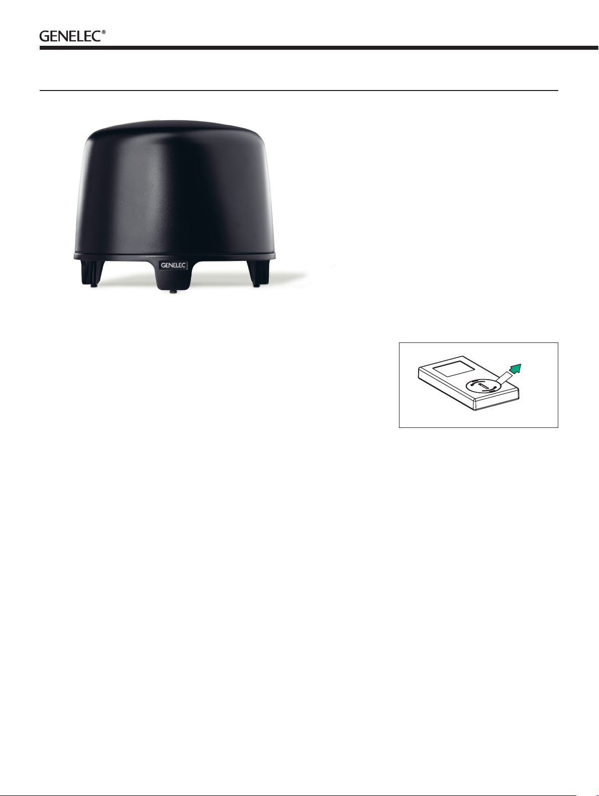
Pull out the battery insulating strip from
the underside of the remote control as
shown in figure 1. This strip insulates the
battery from the contacts on the remote
control during shipping and the remote control does not function before it is removed.
The subwoofer is equipped with six RCA
signal inputs (L, R, C, LS, RS and LFE/LINK
IN) and two balanced XLR inputs (LEFT,
RIGHT). These allow connecting the F Two
to a variety of line level audio sources with
either unbalanced RCA or balanced XLR
type audio connectors. Suitable sources are
preamplifiers, computer sound cards, portable audio players, “PRE OUT” connectors
on a Home Theater receiver, etc.
The output section of the subwoofer contains corresponding L, R, C, LS and RS RCA
connectors for the main loudspeakers, a
LINK OUT RCA connector for linking multiple
subwoofers together and two balanced male
XLR connectors (LEFT, RIGHT).
The L and R RCA inputs and outputs are
working in parallel with LEFT and RIGHT
XLR inputs and outputs.
As the F Two contains its own amplifier, no
separate power amplifier is needed. Never connect the F Two to the loudspeaker outputs of a
power amplifier, integrated amplifier or receiver.
Connecting a stereo system
Connect the audio signal cables from your
source to the corresponding input connectors. The F Two offers both balanced and
unbalanced signal routes. For stereo signals,
use either the LEFT and RIGHT XLR inputs
or the L and R RCA inputs. Next, connect
the subwoofer to the main loudspeakers with
RCA or XLR cables from the corresponding
output (OUT) connectors on the subwoofer
to the signal inputs of the main loudspeakers.
You can also connect an unbalanced
Figure 1. Removing the battery insulating strip
from the remote control
source to the RCA L and R inputs and use
the
parallel LEFT and RIGHT XLR output
connectors as outputs. This provides balanced signal from the subwoofer onwards,
and facilitates easy connection to main loudspeakers with XLR inputs, such as the G
Three or G Four.
Connecting a
surround system
The F Two has an integrated crossover network for the five main channels which directs
the frequencies below 85 Hz to the subwoofer
and higher frequencies through the output
connectors to the main loudspeakers. When
using a surround sound processor, select a
loudspeaker setting “Large” for the channels
routed through the subwoofer.
Connect the five main channel signal RCA
cables from the signal source to the RCA
input connectors L, R, C, LS and RS.
The LFE channel of the preamplifier or
processor can be connected to the LFE IN/
Page 3
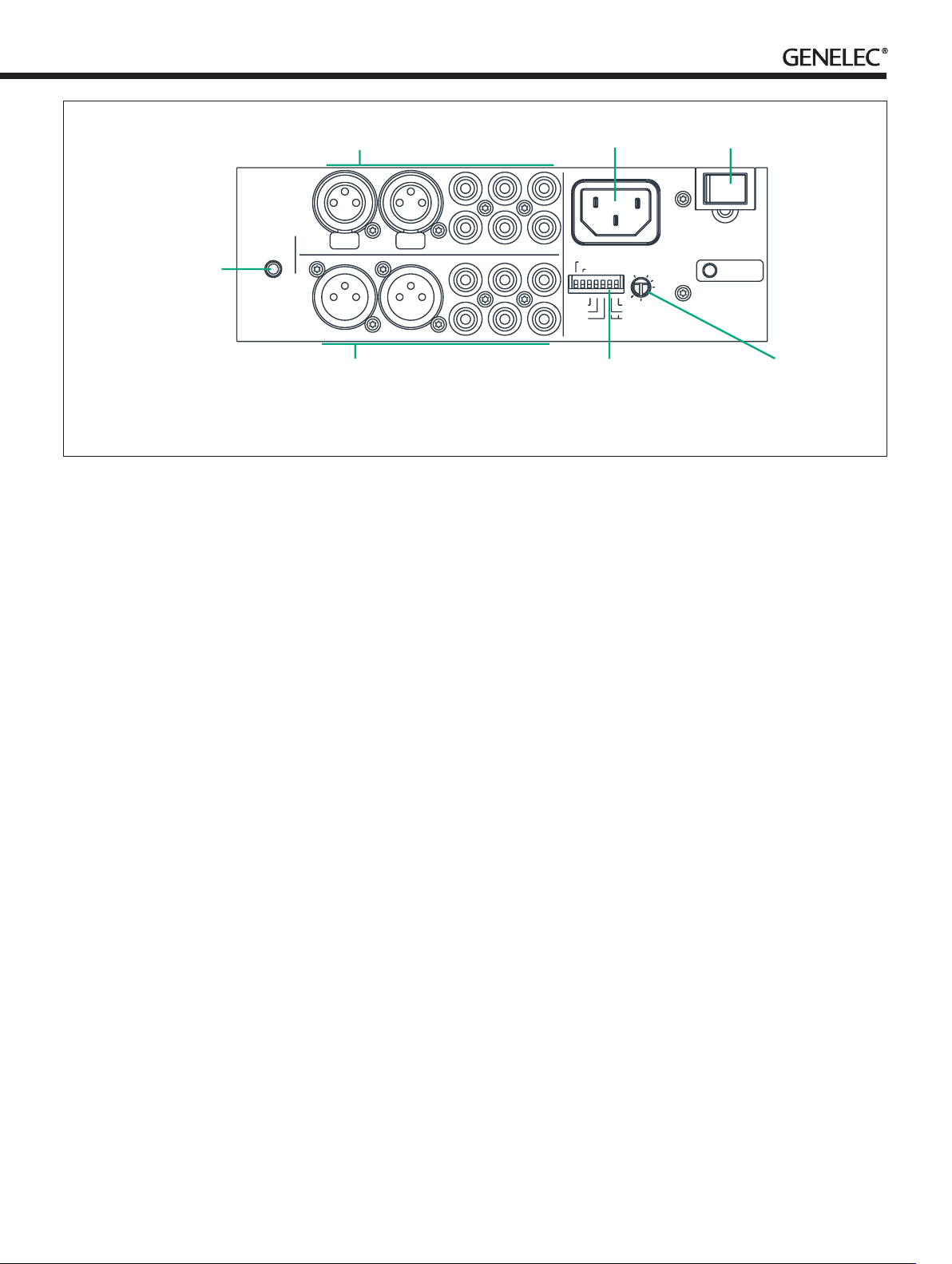
INPUT CONNECTORS
MAINS INPUT
POWER SWITCH
IN
CONNECTOR
FOR OPTIONAL
SYSTEM
VOLUME
CONTROL
WIRED SYSTEM
VOLUME CONTROL
OUT
OUTPUT CONNECTORS
Figure 2. Connectors and controls of the F Two.
LINK IN connector. The LFE channel on the
F Two can reproduce signals up to 120 Hz.
Next connect the main loudspeakers to the
corresponding L, R, C, LS and RS signal outputs on the subwoofer with RCA cables.
Once all connections have been made, the
subwoofer and main loudspeakers are ready
to be powered up.
Positioning in the room
The placement of the subwoofer in the room
affects the overall frequency response and
sound level of the system dramatically, as at
low frequencies the effects of the room are
strong. Even a slight change in the location of
the subwoofer can cause a marked difference
in the frequency balance and often patient
and methodical experimentation and testing
is needed to find the optimum placement.
The placement will also affect the bass
roll-off rate and the phase difference between
the main loudspeakers and the subwoofer.
These effects can be compensated using the
controls in the subwoofer but we recommend
that at first you leave the switches untouched
and concentrate on finding the position where
the subwoofer gives the smoothest response,
and only then use the controls to fine-tune
the balance and phase alignment between
the subwoofer and the main loudspeakers.
Start by placing the subwoofer close to the
center of the front wall. We recommend a distance of less than 60 cm / 24” to the wall. This
LS
L
LEFT
LEFT
RIGHT
RIGHT
R
RS
LS
L
R
RS
position gives increased acoustic loading and
sound pressure level due to the proximity of
the front wall and floor. Ideally the subwoofer
and main loudspeakers should be positioned
symmetrically and at an equal distance from
the listening position.
If the frequency balance is not quite right,
try moving the subwoofer to the left or right
along the wall so that different room modes
are excited at different levels. Positioning
the subwoofer close to a corner will boost
the bass level at lower frequencies and may
cause asymmetrical spatial imaging.
Setting the playback level
The “LEVEL +10 dB” switch on the subwoofer’s connector panel should be switched to
“ON” when the F Two is used with Genelec G
Three or G Four active loudspeakers and the
“LEVEL +10 dB” switches on the main loudspeakers are set to “1.”
Setting the Bass
Roll-Off switches
The acoustic response of the subwoofer
may have to be matched to the characteristics of the room and the positioning in which
it will be used (see Table 1). To adjust the
subwoofer to match these characteristics
use the ‘’BASS ROLL-OFF’ control switches
located on the connector panel. When all
Roll-Off switches are ‘OFF’, a flat anechoic
response is obtained.
C
LFE/LINKIN
C
LINK OUT
ON
-6 dB
-4 dB
-2 dB
LINK IN
LEVEL +10dB
BASS
ROLL-OFF
SUBWOOFER
LEVEL
MAX
-180°
-90°
-270°
PHASE
MIN
CONTROL SWITCHES
-LINK IN
-LEVEL+10 dB
-BASS ROLL-OFF
-PHASE
The effect of incorrect phase alignment
between the main loudspeakers and the
subwoofer is a drop in the frequency
response of the whole system at the main
loudspeaker / subwoofer crossover frequency. The phase difference between the
main loudspeakers and subwoofer at the
listening position is dependent upon the distance from the listener to the subwoofer in
relation to the main loudspeakers. To avoid
phase differences between the left and right
main loudspeakers and the subwoofer, the
subwoofer should be placed close to the
center of the front loudspeaker array.
crossover allow compensation for incorrect
phase alignment. Four settings are provided
between 0° and -270°.
Connect an audio frequency signal generator
to a signal input on the subwoofer which has
a main loudspeaker connected to the corresponding “OUT” connector. Set the generator
to 85 Hz. If a signal generator is not available,
it is possible to use an audio test recording
which has a test frequency in the range 70
Hz to 100 Hz. Suitable test signals can be
downloaded at www.genelec.com.
MAINS INPUT
50/60Hz
120 W 230 V~
ON
POWER
SUBWOOFER LEVEL
ADJUSTMENT
Setting the phase control
Two phase matching switches in the
Coarse phase
correction method
Page 4
Subwoofer
OFF
placement
Near a wall -4 dB (sw 4 “ON”)
In a corner -6 dB (sw 3 “ON”)
Table 1. Suggested Bass Roll-Off settings in
typical situations
ON
7
6
5
OFF
ON
7
6
5
OFF
Bass Roll-Off
Toggle the -180° phase
switch ‘ON’ and ‘OFF’
and set it to the position which gives the
lowest sound level at
the listening position.
Next toggle the
-90°phase switch ‘ON’
and ‘OFF’, and again
set it to the position which gives the
lowest sound level.
Finally, set the
-180°phase switch to
the opposite setting.
ON
7
6
5
Using the F Two subwoofer
When the subwoofer is powered up or after
being disconnected from the mains supply,
the power indicator LED blinks and the
subwoofer stays muted for approximately
seven seconds. This is normal and after this
the LED lights up and playback begins.
The delay allows matching the remote
control to a specific subwoofer unit (see
chapter “Matching the remote control to the
subwoofer” below). This is only necessary
when there are several F Two subwoofers
within the range of the remote control (in
adjacent rooms, for instance) and the user
wishes to avoid the situation that more than
one subwoofer reacts to the commands
given by the remote control.
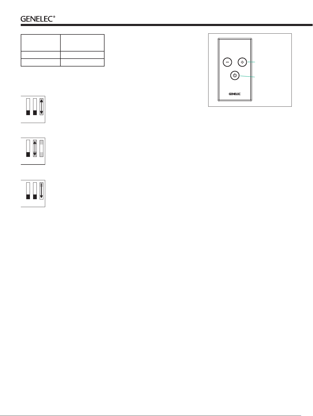
The playback volume can be adjusted with
the “+“ and “-“ buttons on the remote control
(see Figure 3). The LED on the subwoofer
connector panel blinks while the adjustment
is being done and stops blinking when the
minimum or maximum level of the adjustment
range is reached.
The F Two can be muted by a short push
on the POWER/STANDBY button. A new short
push on the POWER/STANDBY button or the +
button resumes playback. The power indicator
LED blinks approximately once per second to
indicate that the subwoofer is in “mute” mode.
Pushing the “-“ button while the subwoofer is
muted reduces the volume setting.
Switch the F Two to stand-by mode by
pushing and holding the POWER/STANDBY
button down until the power indicator LED
switches off. Respectively, the subwoofer
powers up again with a push on the POWER/
STANDBY button.
The F Two is equipped with an automatic
signal sensing function that switches the
subwoofer to stand-by mode if no signal is
present in the audio input for approximately
one hour. The subwoofer resumes playback
automatically when it detects an audio signal
being fed into any of the input connectors.
Alternatively, the subwoofer can be activated
by pushing any button on the remote control.
Automatic protection function
The F Two has an integrated protection function that automatically reduces the playback
volume to a safe level if the subwoofer is
overloaded. This function overrides commands given with the remote control. If this
occurs frequently, reduce the playback level
until the subwoofer starts to function normally.
Matching the remote control
to the subwoofer
When shipped, the remote controls delivered
with F Two subwoofers will function with any
other F Two subwoofer as well. If this is not
desirable, for instance when there are several
F Two subwoofers in the same premises, and
the user wishes to avoid the situation that more
than one subwoofer reacts to the commands
given by each remote control, the remote
controls can be matched to operate only one
subwoofer. This can be done during the seven
second delay in powering up that follows after
connecting the subwoofer to the mains supply.
1. Disconnect the power supply from the
mains connector for a moment and reconnect it or use the power switch to temporarily
switch off the subwoofer. The power indicator
LED will start blinking indicating the seven
second delay.
2. During the delay, first press and hold
down the volume “+“ button on the remote
control and then the volume “-“ button. Keep
both buttons pressed for a few seconds until
VOLUME
CONTROL
BUTTONS
POWER /
STANDBY
BUTTON
Figure 3. F Two remote control
the power indicator LED on the subwoofer
stops blinking. This indicates that matching
is completed.
Now the subwoofer should only respond
to commands given by the matched remote
control, and respectively, the matched
remote control should not work with other
F Two units.
Using multiple subwoofers
The Genelec F Two subwoofer is equipped
with a LINK OUT connector to provide an
easy way of coupling two or more subwoofers together in high SPL applications, for
instance when using the subwoofers with
Genelec G Four active loudspeakers. Connected as described below, the “master”
subwoofer controls the volume of all subwoofers linked to it through this connector.
Connect an RCA cable from the LINK OUT
connector of the “master” subwoofer to which
the main loudspeaker channels are connected, to the LFE / LINK IN connector of the
other, “slave” subwoofer and turn the LINK IN
dip switch on the “slave” subwoofer to “ON”.
In the LINK IN mode, the subwoofer level is
automatically set to maximum and the “slave”
subwoofer does not react to volume control
commands given with a remote control. It
only follows the volume adjustment done in
the “master” subwoofer.
When two subwoofers connected in this
way are positioned close to one another,
bass level increases by 6 dB. Three subwoofers give an SPL increase of 9.5 dB and
four subwoofers 12 dB compared to a single
subwoofer.
The rotary “SUBWOOFER LEVEL” adjustment knob should be turned counter-clockwise to the next line mark on its scale. Phase
and Bass Roll-Off adjustments should be
done individually for each subwoofer in the
Page 5

chain, especially if they are not placed close
together. To check the phase alignment for
the “master” subwoofer switch off the “slave”
subwoofer and follow the instructions given in
the previous sections.
To adjust the phase alignment of the “slave”
subwoofer, you need to switch off the “master”
subwoofer, connect a signal cable from the
“slave” subwoofer’s “C“ channel output connector to the center channel loudspeaker and
switch the LINK IN switch to “OFF”. This effectively changes the “slave” to “master” mode
and the phase adjustment can be carried out.
If you have a stereo system use either “L” or
“R” channel to complete the adjustments.
Return the connections and LINK IN setting
on the “slave” subwoofer back to the “ON”
mode after completing the adjustment.
Safety considerations
The Genelec F Two complies with international safety standards. However, to ensure
safe operation and maintain the equipment in
safe operating condition the following warnings and cautions must be observed.
• Do not use this product with an
unearthed mains cable or a mains
connection without the protective earth
contact as this may lead to personal injury.
• Danger of explosion if battery is
incorrectly replaced. Replace only with the
same or equivalent type.
• The battery shall not be exposed to
excessive heat such as sunshine, fire or
the like.
• Servicing and adjustment must only be
performed by qualified service personnel.
• Opening the subwoofer is strictly
prohibited except by qualified service
personnel.
• Do not expose the subwoofer to water
or moisture. Do not place any objects
filled with liquid, such as vases on the
subwoofer or near it.
• Note that the amplifier is not completely
disconnected from the AC mains service
unless the mains cable is removed from
the amplifier or the mains outlet.
Warning!
This equipment is capable of delivering sound
pressure levels in excess of 85 dB, which
may cause permanent hearing damage.
Compliance to FCC rules
Remote control
This device complies with Part 15 of the FCC
Rules. Operation is subject to the following
two conditions:
(1) this device may not cause harmful
interference, and (2) this device must accept
any interference received, including interference that may cause undesired operation.
This product emits radio frequency energy,
but the radiated output power of this device
is below FCC radio frequency exposure
limits. This equipment complies with FCC RF
radiation exposure limits forth for an uncontrolled environment. Nevertheless, the device
should be used in such a manner that the
potential for human contact with the antenna
during normal operation is minimized.
Changes or modifications not expressly
approved by the party responsible for compliance could void the user’s authority to operate the equipment.
Subwoofer
This device complies with part 15 of the FCC
Rules. Operation is subject to the following
two conditions:
• This device may not cause harmful
interference, and
• This device must accept any
interference received, including
interference that may cause undesired
operation.
Note: This equipment has been tested
and found to comply with the limits for a
Class B digital device, pursuant to part 15
of the FCC Rules. These limits are designed
to provide reasonable protection against
harmful interference in a residential installation. This equipment generates, uses and
can radiate radio frequency energy and, if
not installed and used in accordance with
the instructions, may cause harmful interference to radio communications. However,
there is no guarantee that interference will
not occur in a particular installation. If this
equipment does cause harmful interference
to radio or television reception, which can be
determined by turning the equipment off and
on, the user is encouraged to try to correct
the interference by one or more of the following measures:
• Reorient or relocate the receiving
antenna.
Figure 4. Changing the remote control battery
• Increase the separation between the
equipment and receiver.
• Connect the equipment into an outlet
on a circuit different from that to which the
receiver is connected.
• Consult the dealer or an experienced
radio/TV technician for help.
Modifications not expressly approved
by the manufacturer could void the user’s
authority to operate the equipment under
FCC rules.
Changing the remote control
battery
The remote control battery can be changed
by turning the battery cover on the back of
the remote control anticlockwise. Use a small
screwdriver under the right side of the battery (see figure 4) to wedge the battery out.
Replace the battery with a similar CR2032
type battery. Insert the battery with the left
side first as shown in figure 4 and close the
battery cover.
Take the used battery to your local battery recycling point. Under no circumstances
should the battery be disposed with general
dry waste.
Maintenance
There are no user serviceable parts inside
the subwoofer. Any maintenance of the unit
must only be performed by qualified service
personnel.
Guarantee
This product is supplied with two year guarantee against manufacturing faults or defects
that might alter the performance of the unit.
Refer to supplier for full sales and guarantee
terms.
Page 6

SYSTEM SPECIFICATIONS
F Tw o
Free field frequency response (± 3 dB) Main 27 Hz...85 Hz
Maximum short term sine wave SPL output
averaged from 30 to 85 Hz, measured in half
space at 1 meter
Self generated noise level in half space at 1 m
on axis (A-weighted)
Driver, magnetically shielded 205 mm (8")
Weight 9.8 kg (21.6 lb)
Dimensions
Height
Diameter
LFE 27 Hz...120 Hz
102 dB
≤ 15 dB SPL
300 mm (1113/16”)
362 mm (141/4”)
CONNECTORS
F Tw o
RCA input connectors
RCA output connectors
XLR input connectors
XLR output connectors
Input impedance 10 kOhm
6 (5+LFE/LINK IN)
6 (5+LINK OUT)
2
2
AMPLIFIER SECTION
F Tw o
Amplifier short term output power
(Long term output power is limited by driver
unit protection circuitry)
Amplifier system THD at nominal output ≤ 0.05 %
Mains voltage 100, 120 or 230 V
Power consumption (average)
Stand by
Idle
Full output
150 W
0.5 W
12 W
120 W
CROSSOVER SECTION
F Tw o
Subsonic filter (18 dB/octave) below 27 Hz
Crossover frequency
(subwoofer/main channels)
LFE channel cutoff frequency 120 Hz
Midband rejection >400 Hz >50 dB
Input level for 90 dB SPL output at 1 m -18 dBu at level control
Sensitivity adjustment range 18 dB
Bass Roll-Off control operating range
in 2 dB steps
Phase matching control in 90° steps From 0 to -270° @ 85 Hz
85 Hz
max
From 0 to -6 dB @ 27 Hz
Page 7

F Two Aktiivisubwoofer
Yleistä
Genelec F Two on kompakti aktiivisubwoofer, joka on tarkoitettu tukemaan Genelec
G One- ja G Two-aktiivikaiuttimia stereotai surroundjärjestelmissä ja suurempia G
Three-aktiivikaiuttimia stereojärjestelmissä.
Kaksi tai useampia F Two-subwooferia voidaan ketjuttaa yhteen, jolloin niiden äänenpainekapasiteetti riittää käyttöön myös
Genelec G Four-mallin kanssa.
F Two:n bassotoisto ulottuu 27 hertsiin
saakka, ja sen liitännät mahdollistavat helpon
kytkennän ja yhteensovittamisen pääkaiuttimien kanssa. Koko järjestelmän äänenvoimakkuutta voidaan säätää F Two:n mukana
toimitettavalla langattomallla kaukosäätimellä. Lisävarusteena on saatavissa myös
pöydälle sijoitettava langallinen kaukosäädin.
F Two:ssa on sisäänrakennettu bassonhallinta viidelle pääkanavalle,
taa pääkanavien signaaleista alle 85 hertsin
taajuudet subwooferin toistettaviksi, ja ohjaa
korkeammat antoliitäntöjen kautta pääkaiuttimille.
joka suodat-
Käyttöönotto
Varmista, että kaikista laitteista on kytketty
virta pois.
Vedä pois kaukosäätimen pariston
eristysliuska kuvan 1 mukaisesti. Liuska
eristää pariston toisen navan johdinpinnastaan, joten kaukosäädin ei toimi ennen
kuin se on poistettu.
Subwooferissa on audiosignaaleille kuusi
RCA-ottoliitintä (L, R, C, LS, RS ja LFE/
LINK IN) ja kaksi symmetristä XLR-ottoliitintä (LEFT, RIGHT). F Two voidaan liittää
linjatasoista signaalia antaviin äänilähteisiin, kuten etuvahvistimeen, tietokoneen
äänikorttiin, kannettaviin mp3- ja CD-soittimiin tai kotiteatterivahvistimen ”PRE OUT”liittimiin.
pääkanavalle (L, R, C, LS ja RS), ”LINK OUT”
RCA-liitin useamman subwooferin ketjuttamiseen ja kaksi symmetristä XLR-antoliitintä
(LEFT, RIGHT).
LEFT ja RIGHT XLR-liittimien kanssa.
F Two:ssa on viisi RCA-antoliitintä viidelle
L ja R RCA-liittimet on rinnankytketty
Kuva 1. Kaukosäätimen pariston eristysliuskan
poistaminen
Koska F Two sisältää oman päätevahvistimen, sitä ei koskaan saa kytkeä integroidun
vahvistimen passiivikaiuttimille tarkoitettuihin
kaiutintasoisiin liitäntöihin.
Stereojärjestelmän
kytkeminen
Kytke äänilähteeltä tulevat signaalikaapelit
subwooferin ottoliittimiin. Kaksikanavainen
signaali voidaan tuoda subwooferiin joko
L ja R RCA-liittimien tai LEFT ja RIGHT
XLR-liittimien kautta. Voit käyttää molempia
liitäntöjä samanaikaisesti kahden äänilähteen kytkemiseen, mutta joissakin tapauk-
Page 8

OTTOLIITÄNNÄT
VERKKOVIRRAN LIITIN
VIRTAKYTKIN
IN
LISÄVARUSTEENA
TOIMITETTAVA N
SYSTEM
VOLUME
CONTROL
LEFT
LANGALLISEN
KAUKOSÄÄTIMEN
LIITIN
OUT
LEFT
ANTOLIITÄNNÄT
Kuva 2. F Two:n liitännät ja kytkimet.
sissa tämä voi aiheuttaa kohinatason nousemista.
S
euraavaksi kytke signaalikaapelit subwooferin antoliittimistä (L ja R RCA tai
LEFT ja RIGHT XLR) pääkaiuttimien ottoli-pääkaiuttimien ottoliittimiin.
Voit myös kytkeä äänilähteen subwooferin
RCA L ja R ottoliittimiin ja käyttää antoliitäntöinä niiden kanssa rinnan kytkettyjä
LEFT ja
RIGHT XLR-antoliittimiä. Näin saat käyttöön
symmetrisen signaalitien subwooferin ja
pääkaiuttimien välille, mikä parantaa häiriönsietoa ja helpottaa XLR-liittimillä varustettujen aktiivikaiuttimien (esim. Genelec G Three
ja G Four) liittämistä F Two:hon.
Surroundjärjestelmän
kytkeminen
F Two-subwoofer on varustettu jakosuotimella,
joka suodattaa kaikkien viiden pääkanavan
signaaleista alle 85 hertsin taajuudet subwooferin toistettaviksi, ja ohjaa korkeammat
antoliitäntöjen kautta pääkaiuttimille. Näin subwoofer ottaa kantaakseen osan pääkaiuttimien
bassokuormasta. Kun pääkanavat on kytketty
tällä tavoin subwooferin kautta, tulee surround-dekooderin kaiutinasetuksissa käyttää
asetusta ”suuri” (Large) kaikille pääkaiuttimille.
Kytke äänilähteeltä tulevat pääkanavien
signaalikaapelit F Two:n RCA-ottoliittimiin L,
R, C, LS ja RS.
Kytke äänilähteen LFE-kanava subwooferin LFE IN/LINK IN-ottoliitäntään.
F Two:n
LS
RIGHT
RIGHT
L
R
L
R
C
LFE/LINKIN
RS
LS
RS
C
LINK OUT
ON
-6 dB
-4 dB
-2 dB
LINK IN
BASS
ROLL-OFF
LEVEL +10dB
PHASE
SÄÄTÖKYTKIMET
-LINK IN
-LEVEL+10 dB
-BASS ROLL-OFF
-VAIHE
LFE-kanavan ylärajataajuus on 120 Hz, mikä
on yhteensopiva yleisimpien tallennusformaattien kanssa.
Seuraavaksi kytke signaalikaapelit subwooferin antoliittimistä (L, R, C, LS ja RS)
pääkaiuttimien ottoliittimiin.
Kytke laitteet päälle vasta kun kaikki signaalijohdot on saatu liitettyä paikoilleen.
Subwooferin sijoitus
Bassotoiston taso ja tasapaino riippuu suuressa määrin bassotaajuuksia tuottavan kaiuttimen sijainnista huoneessa. Suhteellisen
pienikin siirtäminen voi aiheuttaa merkittävän
muutoksen sointitasapainoon. Subwooferin
oikean paikan etsimiseen kannattaakin paneutua kärsivällisesti ja huolellisesti ja jättää herkkyys- vaiheenkääntö- ja basson tason säädöt
alkuasetuksiinsa, kunnes akustisesti edullisin
sijoitus on löydetty. Sen jälkeen niitä voidaan
käyttää toiston lopulliseen hienosäätöön.
Hyvä sijoitus löytyy usein etukaiuttimien
takana olevalta seinältä, hieman sivussa huoneen keskilinjalta. Subwoofer kannattaa pitää
lähellä seinää, alle 60 cm:n etäisyydellä. Tällöin subwoofer toimii neljännesavaruudessa
(kahden rajapinnan risteyksessä), mikä tukee
sen bassotoistoa ja eliminoi haitalliset heijastukset etuseinästä ja lattiasta. Etukaiuttimien
takana oleva seinä voi aiheuttaa äänenlaatua
heikentäviä heijastuksia, jolloin kaiuttimesta
taaksepäin säteilevät ääniaallot kimpoavat
seinästä ja summautuvat viivästyneinä kai-
ON
POWER
SUBWOOFER
LEVEL
MAX
MIN
-180°
-90°
-270°
MAINS INPUT
50/60Hz
120 W 230 V~
SUBWOOFERIN
ÄÄNENVOIMAKKUUDEN
PERUSSÄÄTÖ
uttimesta kuuntelupaikalle suuntautuvaan
ääneen. Tämä ongelma voidaan minimoida
käytettäessä subwooferin sisäistä 85 hertsin
jakosuodatusta ja siirtämällä etukaiuttimet
vähintään 110 cm:n etäisyydelle seinästä.
Ellei bassotoisto ole tasapainossa, siirrä
subwooferia vasemmalle tai oikealle. Nurkkaan sijoittaminen korostaa bassotaajuuksia
ja saattaa vääristää akustista tilavaikutelmaa.
F Two:n käyttö eri
pääkaiuttimien kanssa
F Two-subwooferin ”LEVEL +10 dB”-kytkimen perusasetus Genelec G -sarjan aktiivikaiuttimien kanssa on ”OFF.”
Käytettäessä subwooferia Genelec G
Three- tai G Four-aktiivikaiuttimien kanssa.
kun pääkaiuttimien “LEVEL +10 dB”-toiminto
on käytössä, tulee subwooferin “LEVEL +10
dB”-kytkin kääntää asentoon “ON”.
Subwooferin
äänenvoimakkuuden
perussäätö
Subwooferin ja pääkaiuttimien äänenvoimakkuuserojen tasoittamiseksi F Two on varustettu äänenvoimakkuuden perussäädöllä.
Säädin (SUBWOOFER LEVEL) on subwooferin pohjalevyssä. Subwooferin äänen voimakkuus lisääntyy säädintä myötäpäivään
kiertämällä ja vähenee säädintä vastapäivään kiertämällä. Vakioasetus säädölle on -6
dBu (kello 9).
Page 9

Subwooferin
sijoitus
Lähellä seinää -4 dB (sw 4 “ON”)
Nurkassa -6 dB (sw 3 “ON”)
Taulukko 1. Ohjeellisia Bass Roll-Off -säädön
asetuksia tyypillisissä tilanteissa.
Bass Roll-Off
Lopuksi käännä
-180° vaihekytkin
OFF
vastakkaiseen
asentoonsa.
ON
7
6
5
Subwooferin käyttö
ÄÄNENVOIMAKKUUDEN
SÄÄTÖ
VIRTAPAINIKE
Basson tason säätimet
Subwooferin alimpien taajuuksien toistoa
voidaan muokata vastaamaan kulloistakin akustista ympäristöä basson säätimillä
(BASS ROLL-OFF). Pohjalevyssä olevilla
kytkimillä voidaan vaimentaa bassotoistoa
kahden desibelin portain. Taulukossa 1 on
esitetty suuntaa-antavia säätöohjeita.
Vaiheen säätö
Subwooferin ja pääkaiuttimien virheellinen
vaiheistus aiheuttaa vaimentuman niiden
väliselle jakotaajuudelle. F Two on varustettu
neliportaisella 0°...-270° asteen vaiheensäädöllä, jolla tätä virhettä vidaan korjata. Vaiheero riippuu subwooferin ja pääkaiuttimien
keskinäisestä sijainnista, joten sitä kannattaa
lähteä korjaamaan vasta kun subwoofer ja
kaiuttimet ovat lopullisilla sijoituspaikoillaan
.
Vaiheen säätö
testisignaalin avulla
Kytke subwoofer ja vain yksi pääkaiuttimista
päälle ja soita 85 hertsin pistetaajuutta. Sopivan 85 hertsin signaalin voit löytää Genelecin
kotisivun Tuotetuki-osiosta, audiolaitteiden
säätöön tarkoitetuilta testilevyiltä tai tuottaa
sopivalla signaaligeneraattorilla.
Käännä -180°
OFF
vaihekytkin
vuoroin päälle ja
pois, ja jätä se
ON
OFF
siihen asentoon,
jolla bassotoisto
kuuntelupaikalla
on vaimeampi.
Tee samoin -90°
vaihekytkimelle.
7
6
5
ON
7
6
5
Kun F Two kytketään sähköverkkoon ensi
kerran tai oltuaan verkosta irrotettuna, LEDvalo liitinpaneelissa vilkkuu ja subwoofer
pysyy mykistettynä noin seitsemän sekunnin
ajan. Tämän jälkeen subwoofer alkaa toimia
normaalisti, ja käynnistyy jatkossa ilman
viivettä, ellei sitä irroteta sähköverkosta. Viiveen aikana subwooferin asetuksia voidaan
muuttaa niin, että se reagoi vain yhteen kaukosäätimeen. Tästä lähemmin kappaleessa
”Subwooferin ja kaukosäätimen yhteensovittaminen.”
Kun pääkaiuttimet on kytketty F Two:n
otto- ja antoliittimien kautta, koko järjestelmän äänenvoimakkuutta voidaan säätää F
Two:n kaukosäätimen ”+” ja ”-” -painikkeilla.
LED-valo subwooferin liitinpaneelissa vilkkuu
säädön aikana ja lakkaa vilkkumasta kun
maksimi- tai minimitaso on saavutettu.
F Two voidaan mykistää lyhyellä painalluksella kaukosäätimen virtapainikkeeseen.
Uusi painallus virtapainikkeeseen tai ”+”
-painikkeeseen palauttaa subwooferin toimintaan. LED-valo vilkkuu noin kerran sekunnissa subwooferin ollessa mykistettynä. Subwooferin äänenvoimakkuusasetusta voidaan
pienentää ”-” -painikkeella mykistystilan
aikana.
F Two kytketään valmiustilaan pitämällä
kaukosäätimen virtapainketta painettuna
kunnes LED-valo sammuu. Subwoofer palautetaan toimintatilaan virtapainikkeen painalluksella.
F Two kytkeytyy automaattisesti valmiustilaan ellei sen ottoliitäntöihin syötetä audiosignaalia noin tuntiin. Subwoofer käynnistyy
tässä tapauksessa automaattisesti kun signaali palaa tai se voidaan käynnistää painamalla mitä tahansa painiketta kaukosäätimessä.
Automaattinen
ylikuormitussuojaus
F Two on varustettu automaattisella ylikuormitussuojauksella, joka alentaa äänenvoimakkuutta mikäli laite uhkaa vaurioitua.
Suojaustoiminnon aktivoituessa subwoofer
Kuva 3. Kaukosäätimen painikkeet.
ei reagoi kaukosäätimellä tehtäviin säätöihin.
Alenna äänenvoimakkuutta jos suojapiiri aktivoituu.
Subwooferin ja
kaukosäätimen
yhteensovittaminen
Tehtaalta toimitettaessa F Two:n mukana
toimitettavat kaukosäätimet toimivat kaikkien F Two-subwoofereiden kanssa. Jos
samoissa tiloissa on useampia F Twosubwoofereita, tämä voi olla epätoivottavaa, koska useammat subwooferit voivat
reagoida vain yhdelle niistä tarkoitettuihin
ohjauskomentoihin.
Tämä voidaan välttää sovittamalla kukin
kaukosäädin käyttämään vain yhtä subwooferyksilöä. Sovitus tehdään seuraavasti:
1. Irrota subwooferin virtajohto pistorasiasta hetkeksi ja kytke se takaisin tai käytä
subwooferin virta katkaistuna liitinpaneelissa olevalla virtakytkimellä. Subwooferin
LED-valo alkaa vilkkua ja subwoofer pysyy
mykistettynä seitsemän sekunnin ajan.
Sovitus tehdään tämän käynnistysviiveen
aikana.
2. Valon vilkkuessa, paina ensin kaukosäätimen ”+” -painike pohjaan ja pidä painettuna.
Tee sama ”-” -painikkeelle ja pidä molempia
painettuina, kunnes F Two:n LED-valo lakkaa
vilkkumasta.
Yhteensovituksen jälkeen kyseinen subwooferyksilö ei reagoi muihin kaukosäätimiin ja
vastaavasti muut subwooferit eivät reagoi
sovitettuun kaukosäätimeen.
Page 10

Useiden subwoofereiden
ketjuttaminen yhteen
Useita Genelec F Two-subwoofereita voidaan ketjuttaa LINK OUT-antoliittimen
kautta. Näin saadaan lisää äänenpainetta,
ja F Two-subwoofereita voidaan käyttää esimerkiksi Genelec G Four-aktiivikaiuttimien
kanssa. Seuraavan ohjeen mukaisesti kytkettynä yksi ”isäntä”-subwoofer ohjaa ketjun
muiden ”orja”-subwoofereiden toimintaa ja
kaikki subwooferit seuraavat yhdenmukaisesti kaukosäätimellä annettuja komentoja.
Kytke äänilähde ja pääkaiuttimet yhteen
subwooferiin, kuten edellä on esitetty. Tämä
on järjestelmän “isäntä”-subwoofer. Kytke
ketjun seuraava subwoofer RCA-johdolla
“isännän” LINK OUT-antoliittimestä “orjan”
LFE / LINK IN-ottoliittimeen. ja käännä LINK
IN-kytkin “orjan” liitinpaneelissa asentoon
ON. Jos käytössä on useampia subwoofereita, ketjua jatketaan vastaavalla tavalla
eteenpäin. Jokaisen “orjan” LINK IN-kytkin
pitää asettaa asntoon ON.
LINK IN-kytkin asettaa subwooferin
äänenvoimakkuuden maksimiin ja estää subwooferin reagoinnin kaukosäätimellä annettuun äänenvoimakkuuden säätöön. Näin se
seuraa vain “isäntä”-subwooferin kautta tehtävää äänenvoimakkuuden säätöä.
Verrattuna yhteen subwooferiin, kaksi
lähelle toisiaan sijoitettua ketjutettua subwooferia tuottaa 6 desibelin lisäyksen maksimiäänenpaineeseen, kolme 9,5 dB ja neljä 12 dB.
Ketjun kaikkien subwooferiden äänenvoimakkuutta tulee alentaa kiertämällä “SUBWOOFER LEVEL” -säädintä liitinpaneelissa
vastapäivään asteikon yhden viivavälin verran
(-3 dB). Vaiheen ja basson tason (Bass RollOff) säätö tehdään jokaiselle subwooferille
erikseen.
Sammuta kaikki ”orja”-subwooferit
”isäntä”-subwooferin vaiheen säädön ajaksi.
Säädä ”orja”-subwoofereiden vaihe yksi
kerrallaan, ”isäntä” ja mahdolliset muut ”orja”subwooferit sammutettuina. Kytke signaalijohto ”orja”-subwooferin ”C” (keskikanava)
-antoliittimestä keskikaiuttimeen (stereojärjestelmässä käytä joko L- tai R- kanavaa) ja
käännä ”LINK IN”-kytkin asentoon ”OFF.” Nyt
voit suorittaa vaiheen säädön.
Säädön jälkeen kytke ”LINK IN”-kytkin
takaisin asentoon ”ON” ja palauta kaapelointi
entiselleen.
taa kuitenkin seurata vaaratilanne, joten
seuraavia ohjeita on aina noudatettava:
• Laitetta ei saa asettaa alttiiksi
kosteudelle tai roiskevedelle. Se on
tarkoitettu käytettäväksi ainoastaan
kuivassa huonetilassa.
• Älä käytä laitetta ilman
suojamaadoitettua verkkojohtoa tai
kytke sitä suojamaadoittamattomaan
pistorasiaan.
• Pariston virheellinen asennus tai
käsittely voi aiheuttaa räjähdysvaaran.
Käytä vain ohjeessa mainitun tyyppisiä
paristoja.
• Paristoa ei saa altistaa kuumuudelle,
kuten voimakkaalle auringonvalolle, tulelle
tai muulle lämmönlähteelle.
• Huolto- ja korjaustoimia saa
suorittaa vain valmistajan valtuuttama
huoltohenkilöstö.
• Älä avaa koteloa tai irrota laitteesta
mitään osia.
• Huomaa, että vahvistin ei ole täysin
jännitteetön ellei virtajohtoa ole irrotettu
pistokkeesta.
VAROITUS!
Genelec F Two pystyy tuottamaan yli 85 desibelin äänenpaineen, mikä voi aiheuttaa pysyvän kuulovaurion.
Kaukosäätimen
pariston vaihto
Irrota kaukosäätomen takana oleva pyöreä
pariston kansi vastapäivään kiertämällä.
Irrota paristo pienellä ruuvimeisselillä vipuamalla oikea laita ensin ylös (huomaa, että
pariston vasen laita menee ”+” -navan kosketinkynsien alle). Vaihda paristo uuteen
CR2032-tyypin paristoon, muuntyyppisten
paristojen käyttö on kielletty. Työnnä paristo
paikalleen vasen laita edellä (katso kuva 4)
ja sulje pariston kansi.
Toimita käytetty paristo paristojenkierrätyspisteeseen, älä laita sitä normaalin sekajätteen sekaan.
Huolto
Kaikki huolto- ja korjaustoimet on annettava valmistajan tai valmistajan valtuuttaman
huoltohenkilöstön suoritettaviksi. Älä avaa
laitetta itse.
Kuva 4. Kaukosäätimen pariston vaihto.
Turvallisuusohjeita
Genelec F Two-subwoofer on suunniteltu ja
valmistettu täyttämään kansainväliset turvallisuusnormit. Virheellisestä käytöstä saat-
Takuu
Genelec Oy antaa tuotteilleen ostopäivästä
lukien kahden vuoden takuun. Takuu kattaa
valmistusvirheet ja materiaaliviat.
Page 11

TEKNISET TIEDOT
F Tw o
Taajuusvaste vapaakentässä (± 3 dB) Pääkanavat 27 Hz...85 Hz
Hetkellinen maksimiäänenpaine mitattuna
sinisignaalilla puoliavaruuteen
(keskiarvo 30...85 Hz 1 m etäisyydellä)
Akustinen pohjakohinataso (A-painotettu) 1 m
etäisyydellä
Kaiutinelementti (magneettisuojattu) 205 mm (8")
Paino 9,8 kg
Mitat
Korkeus
Halkaisija
LFE 27 Hz...120 Hz
102 dB
≤ 15 dB SPL
300 mm
362 mm
LIITÄNNÄT
F Tw o
RCA-ottoliitäntöjä
RCA-antoliitäntöjä
XLR-ottoliitäntöjä
XLR-antoliitäntöjä
Ottoimpedanssi 10 kOhm
6 kpl (5+LFE/LINK IN)
6 kpl (5+LINK OUT)
2 kpl
2 kpl
VAHVISTIN
F Tw o
Vahvistimen lyhytkestoinen teho (kaiutinelementin suojauselektroniikka
rajoittaa vahvistimen jatkuvaa tehoa)
Vahvistimen särö nimellisteholla (THD) ≤ 0.05 %
Verkkojännite 230 V
Tehonkulutus keskimäärin
Valmiustila
Min
Max
150 W
0,5 W
12 W
120 W
JAKOSUODIN
F Tw o
Ylipäästösuodin (18 dB/oktaavi) <27 Hz
Jakotaajuus subwoofer/pääkanavat 85 Hz
LFE-kanavan ylärajataajuus 120 Hz
Vaimennus >400 Hz >50 dB
Herkkyyden säätöalue 18 dB
Bass Roll-Off-säätö 2 dB:n portain 0 ... -6 dB @ 27 Hz
Vaiheen säätö 90 asteen välein 0 ... -270° @ 85 Hz
Page 12

F Two
Operating Manual
Käyttöohje
Genelec Document D0105R004. Copyright Genelec Oy 12.2012. All data subject to change without prior notice
International enquiries:
Genelec, Olvitie 5
FIN-74100, Iisalmi, Finland
Phone +358 17 83881
Fax +358 17 812 267
Email genelec@genelec.com
In the U.S. please contact:
Genelec Inc., 7 Tech Circle
Natick, MA 01760, U.S.A.
Phone +1 508 652 0900
Fax +1 508 652 0909
Email genelec.usa@genelec.com
In China please contact:
Beijing Genelec Audio Co. Ltd.
Jianwai SOHO, Tower 12, Room 2605
39 East 3rd Ring Road, Chaoyang District
Beijing 100022, China
Phone +86 10 5869 7915
Fax +86 10 5869 7914
www.genelec.com
In Sweden please contact
Genelec Sverige
Ellipsvägen 10B
P.O. Box 5521, S-141 05 Huddinge
Phone +46 8 449 5220
Fax +46 8 708 7071
Email info@genelec.com
 Loading...