

Page 1
GLM
dsp
AutoCa
l
TM
System Operating Manual
Page 2

Page 3

3
GENELEC DSP LOUDSPEAKER SYSTEM OPERATING MANUAL
Do not attempt to operate the system without first becoming acquainted with this manual.
Genelec Document D0066R001a. Copyright Genelec Oy 3.2006. All data subject to change
Page 4

4
Table Of Contents
INTRODUCTION .................................................................................................................. 8
GLOSSARY ......................................................................................................................... 9
SYSTEM PARTS .................................................................................................................. 13
Loudspeaker Delivery Content ..............................................................................................13
Subwoofer Delivery Content .................................................................................................13
Contents of the delivery box .................................................................................................13
GLM DSP Loudspeaker Manager Package Delivery Content ..............................................14
GLM DSP Multiroom Expansion Package Delivery Content .................................................14
LOUDSPEAKERS ................................................................................................................ 15
Two-Way Loudspeakers (8200 Series) .............................................................................. 15
Subwoofers (7200 Series) .................................................................................................. 16
GETTING STARTED ............................................................................................................ 18
Quick course to system basics .............................................................................................18
Step-by-step system setup for GLM Control Network use ....................................................21
Step-by-step system setup for Stand-Alone use ...................................................................22
PLACING LOUDSPEAKERS IN THE MONITORING ROOM ............................................. 23
Full-bandwidth loudspeaker placement .................................................................................23
Subwoofer placement ...........................................................................................................25
Multi-channel System Layout ................................................................................................26
GENELEC LOUDSPEAKER MANAGER GLM ................................................................... 28
Overview ............................................................................................................................... 28
GLM Control Network ...........................................................................................................29
GLM Control Network Size ...................................................................................................32
Buying Cables for the GLM Control Network ........................................................................ 32
Installing the GLM Software ..................................................................................................32
Running the System Setup Wizard ....................................................................................... 32
Running the Acoustical Setup Wizard ...................................................................................35
Page 5

5
BASIC USE OF THE GLM ................................................................................................... 36
GLM Main Page .................................................................................................................... 36
Mute All and Bypass BM .......................................................................................................37
Volume Control .....................................................................................................................37
Level Presets ........................................................................................................................39
Access to the GLM System Setup Editors ............................................................................ 39
Information Data Banner .......................................................................................................40
Audio Channel Group Functions ...........................................................................................40
Menu Items ...........................................................................................................................41
RAPID CABLING WIZARD ................................................................................................. 43
How to Use Rapid Cabling ...................................................................................................43
Stereo Pair Analog ................................................................................................................45
5.0 Surround System Analog ................................................................................................ 46
Stereo Pair (AES/EBU Single-Wire) ......................................................................................47
Stereo Pair with Subwoofer (AES/EBU Single-Wire) ............................................................ 48
5.0 Surround System (AES/EBU Single-Wire) ......................................................................49
5.1 Surround System with Subwoofer (AES/EBU Single-Wire) ............................................ 50
6.1 Surround System with Subwoofer (AES/EBU Single-Wire) ............................................ 51
7.1 Surround System with Subwoofer (AES/EBU Single-Wire) ............................................ 53
Stereo Pair (AES/EBU Dual-Wire) ........................................................................................54
Stereo Pair with Subwoofer (AES/EBU Dual-Wire) ...............................................................55
5.0 Surround System (AES/EBU Dual-Wire) ........................................................................56
5.1 Surround System with Subwoofer (AES/EBU Dual-Wire) ...............................................57
MANUAL CABLING WIZARD ............................................................................................. 59
Planning Audio Cabling .........................................................................................................59
Running the Manual Cabling Wizard ....................................................................................64
Saving the Setup ...................................................................................................................72
MANAGING SYSTEM SETUPS .......................................................................................... 73
Saving and Recalling Setups ................................................................................................ 73
Opening the System Setup Editor .........................................................................................74
Editing Audio Cabling Definitions ..........................................................................................74
Editing Group Definitions ......................................................................................................75
Replacing and Removing Loudspeakers in a System Setup File .........................................78
Page 6

6
ACOUSTICAL SETUP WIZARD .......................................................................................... 81
Loudspeaker Placement and Distance .................................................................................82
Aligning Loudspeaker Levels ................................................................................................ 83
Setting Up Subwoofers .........................................................................................................85
AUTOCAL – FULLY AUTOMATED SYSTEM CALIBRATION ............................................ 89
Theory of Operation .............................................................................................................. 89
Setting up for AutoCal ...........................................................................................................90
Running AutoCal ...................................................................................................................92
Subwoofer Phase Aligment using the AutoPhase ................................................................94
Editing AutoCal settings manually ........................................................................................97
Storing settings permanently into loudspeakers ...................................................................97
EDITING ACOUSTIC CALIBRATIONS ............................................................................... 99
Opening the Acoustical Settings Editor .................................................................................99
Two-Way Loudspeakers ........................................................................................................100
Saving and Loading Acoustic Settings ..................................................................................106
Subwoofers ........................................................................................................................... 107
Using the Interactive Response Editor ..................................................................................116
STAND-ALONE OPERATION ............................................................................................. 117
Two-Way Loudspeakers ........................................................................................................117
Front panel warning light .......................................................................................................118
Back Panel Controls .............................................................................................................118
Subwoofers ........................................................................................................................... 120
Connector Panel Details .......................................................................................................122
Storing settings in loudspeakers and subwoofers ................................................................128
Selecting the stored settings ................................................................................................128
FUNCTION REFERENCE .................................................................................................... 129
Desktop Compensation .........................................................................................................129
Genelec AutoCal ...................................................................................................................129
Loudspeakers Online ............................................................................................................ 130
Load Setup ............................................................................................................................130
Wizard Introduction ............................................................................................................... 131
Rapid Cabling Preset Selection ............................................................................................132
Loudspeaker Marking ...........................................................................................................133
System Audio Connections ...................................................................................................134
Page 7

7
Signal Format ........................................................................................................................136
Audio Cabling Summary .......................................................................................................140
Loudspeaker Connection ...................................................................................................... 141
Floating Level Fader .............................................................................................................144
Reference Level Calibration ..................................................................................................144
Vertical Axis Trim ...................................................................................................................146
Index .... 148
Page 8

8
INTRODUCTION
Congratulations and thank-you for the purchase of this Genelec Active Digital Monitor System. These
systems are designed to integrate easily into the digital production environment. There are several ways
to configure and operate the DSP loudspeakers for a wide variety of high quality audio applications. The
two-way loudspeakers have also analog inputs, making them versatile and intelligent replacements for
analog loudspeakers.
This manual addresses the Genelec Loudspeaker Manager GLM™ and the proprietary Genelec
loudspeaker control network, guiding step-by-step through the setup process. The DSP loudspeakers can
also be used in stand-alone mode just like any other loudspeaker but enjoying the benefits of additional
flexibility and versatility.
Genelec Loudspeaker Manager (GLM), Genelec AutoCal, AccuSmooth, SinglePoint, and MultiPoint are
trademarks of Genelec Oy.
Parts of the Genelec Loudspeaker Manager are written using MATLAB®. © 1984 -2005 The MathWorks,
Inc.
Page 9
9
GLOSSARY
.eq1 file A subwoofer acoustical settings file.
.eq2 file A two-way loudspeaker acoustical settings file.
.gtd file
Genelec Time Data file containing the computed impulse
responses of a loudspeaker or subwoofer.
3.5 mm Measurement Signal
Cable
A 3.5 mm stereo jack-to-jack interconnection cable used to
connect the MIC OUT socket on the GLM Network Interface to a
computer’s soundcard input.
AccuSmooth
A proprietary smoothing algorithm that has a higher resolution
(narrower smoothing bandwidth) at low frequencies than a
standard 1/3 octave smoothing, and a similar resolution at
high frequencies. This is used by AutoCal to ensure accurate
placement of notch filters at critical bass frequencies.
Acoustical Settings Editor
A page in the GLM that provides access to the Acoustical Settings
in the loudspeaker or subwoofer. The Interactive Response
Editor can also be accessed here.
Acoustical Setup Wizard
A self-guided Wizard that allows for manual or automated
(AutoCal) calibration of the Loudspeaker Acoustic parameters.
Analog Signal Cable
The GLM supports AES/EBU digital audio cables and analog
audio cables. An analog audio cable carries one channel of
audio. An AES/EBU cable can carry one or two channels of
audio.
Audio channel
Although the definition of an audio channel is rather straightforward
and clear, it should not be confused with loudspeakers or audio
cables in the loudspeaker system. The AES/EBU digital audio
cables may carry one or two audio chanels. There may be one
or more loudspeakers reproducing one audio channel.
Bass Management
Bass Management is used to reproduce the low frequency
content of audio channels over one or more subwoofers instead
of loudspeakers. This can be the low frequency content from
the full-bandwidth audio channels. Parts or the entire LFE audio
channel can also be bass managed.
Digital Signal Cable
The digital signal cable carries an AES/EBU audio signal. The
GLM supports AES/EBU digital audio cables and analog audio
cables. An AES/EBU cable can carry one or two channels of
audio.
Page 10
10
Digital Thru
The connector on the back of a loudspeaker used to pass the
AES/EBU digital audio signal presented to the digital input
connector onto another loudspeaker.
Genelec 8200A Calibration
Microphone
A factory calibrated acoustic measurement microphone used for
AutoCal system alignment.
Genelec AutoCal
Genelec AutoCal is a property of the GLM software that
utilizes built-in test signal generators inside all Genelec DSP
loudspeakers to acoustically measure and align the loudspeaker
system.
Genelec AutoPhase
Genelec AutoPhase is a part of Genelec AutoCal. It aligns the
the phase of the subwoofer(s) in the system to the designated
loudspeaker(s).
GLM Control Network
The GLM loudspeaker control network is a proprietary network
allowing the setting, reading and monitoring of loudspeakers and
subwoofers on the GLM network. System setup can be achieved
very rapidly by simply opening a System Setup file, which
causes all system and loudspeaker settings to be automatically
communicated to all loudspeakers.
GLM DSP Loudspeaker Manager
Package
The GLM control network delivery package containing all
hardware and software to build a GLM Loudspeaker Manager
environment. Loudspeakers and subwoofers are purchased
separately.
GLM DSP Multiroom Expansion
Package
An expansion package providing a license and hardware to
install the GLM in multiple rooms within a single facility.
GLM Main Page
The face of the GLM. This page is used to access all other
functions of Loudspeaker Manager.
GLM Network Interface
The GLM Network Interface is a USB device that connects
the computer to the GLM loudspeaker control network.
The GLM Network Interface translates communication between
the computer and the control network, enabling a very large
and physically long control network with multiple loudspeakers.
The GLM Network Interface isolates the private and confidential
messaging with loudspeakers from any public data networks and
from the functioning of the computer running the GLM software.
GLM System Setup Editor
This page is used to access more detailed sections of the GLM
including the Acoustical Settings Editor.
Page 11
11
GLM Software
GLM is an abbreviation for the Genelec Loudspeaker Manager.
This software enables setup and control of loudspeakers on the
GLM control network through the use of system setup files, and
supports fully automated loudspeaker system setup.
Group
Loudspeakers or audio channels designated to play
simultaneously.
ID Tone
A built-in tone in the DSP loudspeakers and subwoofers used to
identify which loudspeaker is being communicated to.
IEC Mains Cable
A standard detachable mains cable used to apply mains electrical
power to the loudspeaker or subwoofer.
Interactive Response Editor
Located in the Acoustical Settings Editor, this Editor allows for
the interactive adjustment of a measured response using the
Room Response Controls.
Loudspeaker
This term is used for loudspeakers that are not subwoofers. A
8240A or 8250A two-way active DSP loudspeaker.
Manual Acoustic Wizard
A self-guided Wizard that allows for manual calibration of the
loudspeaker acoustic parameters.
Manual Cabling Wizard
A self-guided Wizard that allows for more complicated and
versatile System Setups not found in the Rapid Cabling Wizard.
Manual Controls
The user interface settings on a loudspeaker or subwoofer used
when in stand-alone mode.
Microphone Holder
The rubber mounting hardware to attach the Genelec 8200A
Calibration Microphone to a standard microphone stand.
MultiPoint
A method of spatial averaging used in AutoCal measurements,
used when optimizing the Acoustical Settings.
Network Cable
A CAT5 cable with RJ45 connectors (type PC-to-HUB, straight
not crossed wiring). This cable is also used as an Ethernet
network cable. Network cables connects the GLM Network
Interface to the loudspeakers and subwoofers to form a network
of devices that may be controlled using the GLM software
Network Control Mode
The use of Genelec DSP loudspeakers with the GLM software
and the control network.
Node
Every loudspeaker and the GLM Network Interface is a node on
the GLM control network.
Page 12
12
Rapid Cabling Wizard
The GLM contains pre-made system setups of the most typical
loudspeaker arrangements. Rapid Cabling makes system setup
simple and fast by allows the selection of one of these presets.
Room Response Controls
A collection of controls used to modify the loudspeaker or
subwoofer response in order to improve the in-room sound
quality at the listening position.
SinglePoint
A measurement taken in the main monitoring position used by
AutoCal when optimizing the Acoustical Settings.
Software CD
The CD-ROM containing the install files for Genelec Loudspeaker
Manager and AutoCal.
Stand-Alone Mode
The use of Genelec DSP loudspeakers as individual loudspeakers,
without the GLM software and the control network.
Stored Settings
The settings stored inside a loudspeaker or subwoofer. These
settings are used when the loudspeaker is operated in the stand
alone mode
Subwoofer
A 7260A, 7270A or 7271A active DSP subwoofer with 8 channel
bass management.
System Setup File
Files stored on the hard drive of a computer running the GLM.
Loading a System Setup File in GLM automatically sets up
all loudspeakers in the system with stored monitoring Group
definitions, audio cable definitions, defaults for monitoring levels
and all acoustical alignment settings.
System Setup Wizard
System Setup Wizard guides the user through the process of
setting up the GLM.
Third-party Volume Controller
A peripheral device (e.g. Griffin PowerMate) used to control the
system volume.
USB Cable
A type A-B USB cable used to connect the GLM Network
Interface to a computer.
Page 13

13
SYSTEM PARTS
The Genelec DSP loudspeaker system consists of
• Two-way loudspeakers
• Subwoofers
• GLM Genelec DSP Loudspeaker Manager Package containing the user interface software with
the GLM Control Network Interface and a factory calibrated acoustic measurement microphone for
controlling DSP loudspeakers
• Multiroom Expansion Package
A basic working system requires only loudspeaker(s). See Getting Started.
Loudspeaker Delivery Content
Contents of the delivery box
• Loudspeaker
• IEC Mains Cable
• Network Cable
• Loudspeaker Operating Manual
Subwoofer Delivery Content
Contents of the delivery box
• Subwoofer Loudspeaker
• IEC Mains Cable
• Network Cable
• Subwoofer Operating Manual
Page 14

14
GLM DSP Loudspeaker Manager Package Delivery Content
The GLM™ Genelec Loudspeaker Manager is a loudspeaker control networking system that offers
capability to control all system parameters as well as the possibility for detailed acoustical alignment
of every loudspeaker in the system. The use of the GLM is warmly recommended. Genelec AutoCal™
provides the GLM with a fully automated multi-loudspeaker system acoustical calibration capability and
comes with a factory-calibrated measurement grade microphone, microphone amplifier and microphone
holder.
Contents of the GLM delivery box
• Software CD
• Genelec DSP Loudspeaker System Operating Manual
• Quick Connection Guide
• GLM Network Interface with a built-in calibration microphone amplifier
• USB Cable
• Network Cable
• Genelec 8200A Measurement Microphone
• Microphone Holder
• Measurement Signal Cable with 3.5 mm stereo plugs
GLM DSP Multiroom Expansion Package Delivery Content
The GLM software is sold with a site-license permitting installation into multiple rooms. The GLM DSP
Multiroom Expansion Package delivers a GLM Network Interface and cables for installation into one
additional room. Each additional room needs a multiroom expansion pack.
• GLM Network Interface
• USB Cable
• Network Cable
Page 15

15
LOUDSPEAKERS
This section provides a rapid overview of Genelec DSP loudspeakers. In-depth information about the
DSP loudspeakers is available at www.genelec.com and in the Operating Manuals supplied with the DSP
loudspeakers.
Two-Way Loudspeakers (8200 Series)
The two-way DSP loudspeakers accept both AES/EBU digital audio and analog audio.
Analog input
The analog input on Genelec loudspeakers has a fixed sensitivity. A 0 dBu (0.775 volts) signal produces
a 94 dB SPL at 1 m. The maximum sound pressure level depends on the loudspeaker model. A larger
loudspeaker will produce a higher maximum sound pressure level than a smaller one.
Digital audio input
The digital input has a fixed sensitivity. Digital signals are represented relative to their maximum value, or
Full Scale (FS) value. For example, –10 dBFS means that the digital audio signal level is 10 dB below the
full scale or the maximum representable digital signal.
In Genelec DSP loudspeakers, the maximum theoretical audio level for a 0 dBFS digital audio input
signal translates to 130 dB SPL at 1 m sound pressure level. For example, a signal having -36 dBFS level
produces a sound level of 94 dB SPL at 1 m. This is a technical specification of the loudspeaker, and the
Genelec Loudspeaker Manager GLM can adjust the monitoring volume down from this level.
Digital audio sample rate can vary from 32 kHz to 192 kHz and word length from 16 to 24 bits. Single-Wire
and Dual-Wire signals are automatically detected
Digital audio takes precedence over analog audio. If a valid AES/EBU signal is presented to the
loudspeaker, that input will be selected and the analog audio will mute. Note that there may be a valid
AES/EBU signal although the signal is silent.
Page 16
16
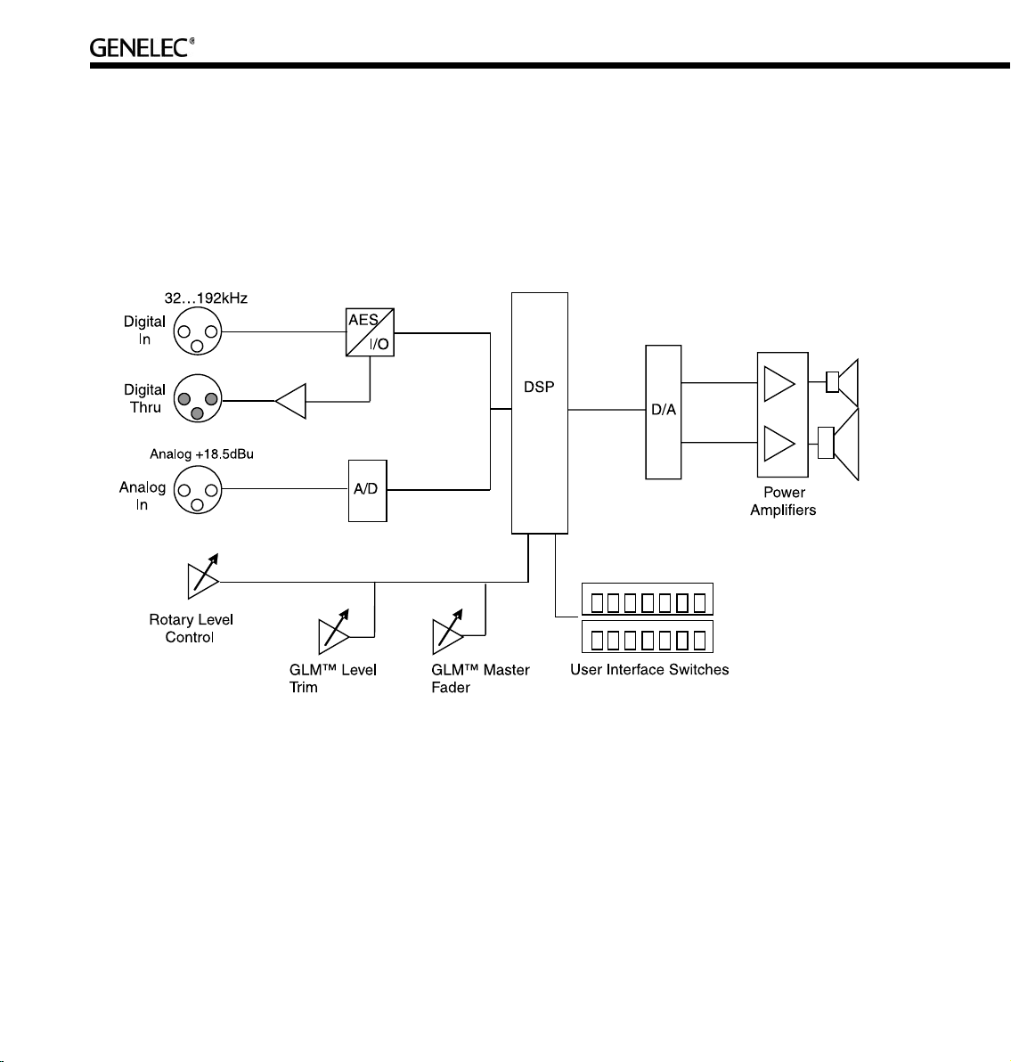
Two-Way Loudspeaker Functional Blocks
All audio enters the DSP processor, where all signal processing and filtering takes place. The audio
outputs go via digital-to-analog conversion to built-in power amplifiers and on to the tweeter and woofer
drivers. The loudspeakers have built-in user interfaces with switches and a rotary level control in the rear
of the loudspeaker, as well as a connection for the Genelec Loudspeaker Manager network enabling
centralized management of up to 30 loudspeakers in one installation.
Subwoofers (7200 Series)
Digital audio input
The digital input has a fixed sensitivity. Digital signals are represented relative to their maximum or Full
Scale value. For example, -10 dBFS means that the signal level is 10 dB below the full scale or the
maximum representable digital signal.
In Genelec DSP subwoofers, the maximum audio level of 0 dBFS translates to the theoretical 130 dB SPL
at 1 m sound pressure level. For example, a -36 dBFS signal produces a sound level of 94 dB SPL at 1
m. Genelec Loudspeaker Manager GLM adjusts the monitoring volume down from this level.
Page 17
17
Digital audio sample rates can vary from 32 kHz to 192 kHz and word length from 16 to 24 bits. SingleWire and Dual-Wire signals are automatically detected. Note that there may be a valid AES/EBU signal
although the signal is silent.
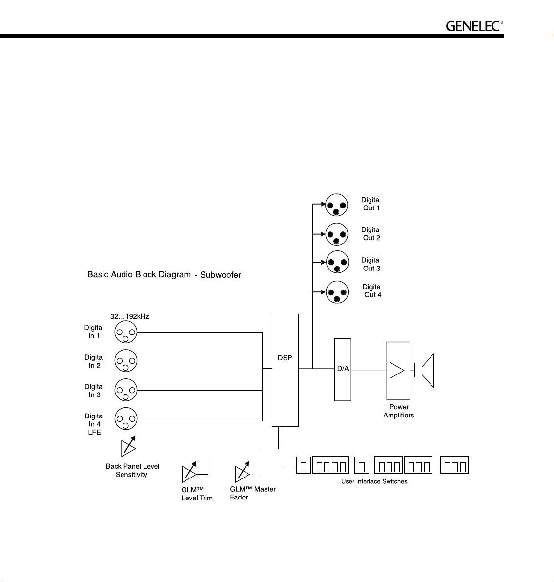
Subwoofer functional blocks
The subwoofers have AES/EBU digital audio inputs only. There are no analog audio inputs. All audio
enters the DSP processor, where all signal processing takes place. The output goes via digital-to-analog
conversion to the built-in power amplifier and driver(s). The subwoofers have a built-in user interface with
switches and rotary controls and a connection to the Genelec Loudspeaker Manager network enabling
centralized management of up to 30 loudspeakers including subwoofers in one installation.
Page 18
18
GETTING STARTED
Quick course to system basics
Control network and audio cabling are separate. The first observation to be made is that audio signals
and control information travel along different cables. This has the inherent advantage of allowing one to
operate the system with the control network (known as the network control mode) or without the control
network if so desired (known as the stand-alone mode).
When using the Genelec loudspeaker control network, full control to all features in a loudspeaker become
available. Attaching the control network automatically puts the loudspeaker in the network-controlled
mode.
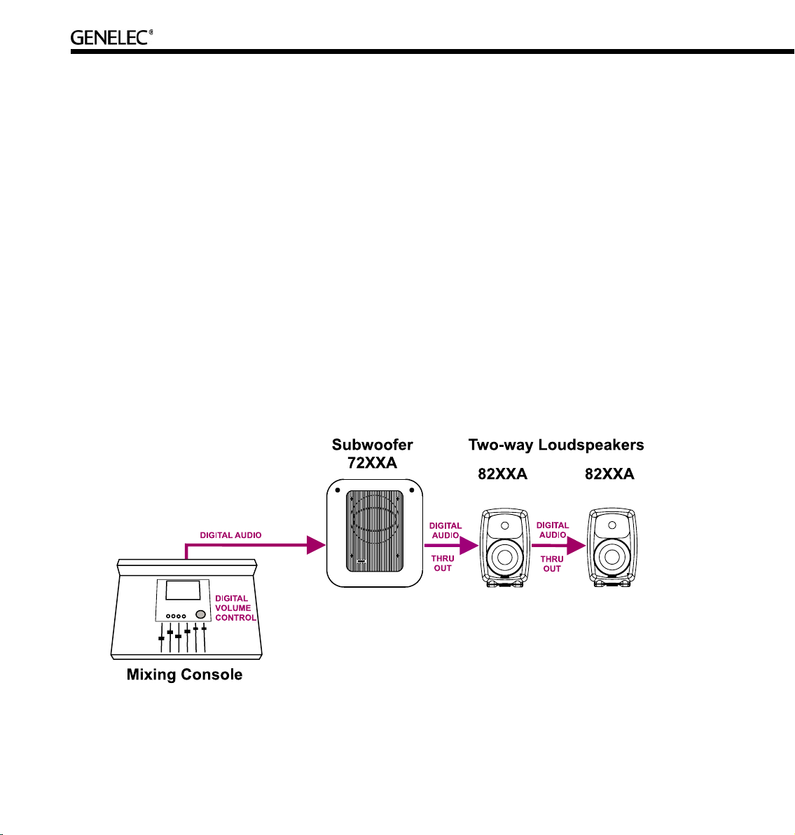
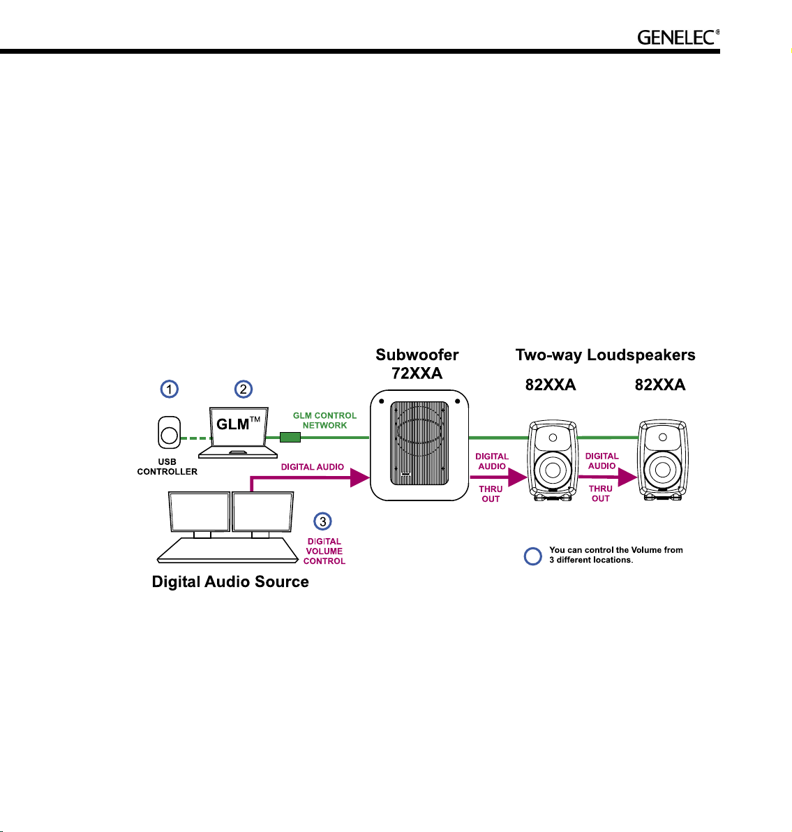
Digital audio. All Genelec DSP loudspeakers and subwoofers have AES/EBU digital audio inputs. When
applicable, run the AES/EBU audio cable(s) to the subwoofer first, then onto the main loudspeakers. If
the AES/EBU cable carries two digital audio channels, run another cable from the “Thru” output of the
loudspeaker to the input of the next loudspeaker.
Page 19
19
If the audio source has a volume control for the AES/EBU digital audio, it can be used to control the
monitoring level.
If the AES/EBU outputs are fixed level line-outs, various volume controls options are available in the GLM
loudspeaker control software.
The GLM software provides several volume control faders on the computer display. These volume controls
can be used in the same computer running audio processing or recording software.
Third-party volume control knobs (for example Griffin PowerMate2) that attach to a USB interface can
also be used to control the monitoring level through the GLM software and the Genelec loudspeaker
control network.
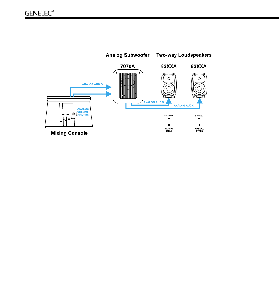
Analog audio. The two-way loudspeakers have an analog audio input and can be connected just like any
other (analog) loudspeaker. They can be used with analog subwoofers and mixed with analog two-way
loudspeakers to build a system. It is easy to achieve good system integration as the input sensitivity of
the DSP loudspeakers is the same as that of the analog loudspeakers.
Page 20
20
Cabling works just like any other analog loudspeaker setup. The analog audio cables are first connected
to a Genelec subwoofer where bass management takes place, and then onwards to the two-way
loudspeakers.
Stand-alone mode refers to using DSP loudspeakers without the GLM Control Network.
Two-way DSP loudspeakers are equipped with both analog and digital inputs, and digital audio takes
precedence over analog audio. In stand-alone mode the analog input works only if there is no AES/EBU
digital audio input to the loudspeaker, for example when the digital cable is removed or the AES/EBU bit
stream is halted at the source.
When using the GLM loudspeaker system control software, it is possible to select between analog and
digital inputs. Analog and digital signals are never mixed.
When calibrating the DSP two-way loudspeakers one can select to use the same switch-based acoustic
alignments that can be found on the analog loudspeakers, or to use a much more versatile set of room
response controls available through the GLM loudspeaker control software and the Genelec loudspeaker
control network link built into all DSP loudspeakers.
Page 21
21
The GLM software runs on any Windows XP or Macintosh OSX computer. The GLM Network Interface
connects the computer to the loudspeakers. Using the GLM software provides full access to all room
response controls. After aligning the loudspeakers acoustically, it is possible to store these settings inside
the loudspeaker’s memory.
Step-by-step system setup for GLM Control Network use
The Genelec DSP loudspeaker family uses a networking concept for controlling a system of loudspeakers.
A control network cable is provided with all Genelec DSP loudspeaker products.
To setup quickly, follow the steps detailed below. For further information consult the sections of this
manual mentioned in each step.
• Unpack and position the loudspeakers. See the “Loudspeaker Placement” section for details.
• Find the Genelec Control Network cables in each loudspeaker delivery box. Connect the control
network. See the “Genelec control network cabling” section for details.
• Find the GLM Network Interface and follow cabling instructions. See the “GLM Network
Interface Device” section for details.
• Launch GLM, then follow the on-screen instructions to complete a System Setup. Select either
Rapid Cabling Mode or Manual Cabling Mode and follow the instructions.
• Select the appropriate Rapid Cabling preset in the GLM and launch the Rapid Cabling Wizard.
See the “Rapid Audio Cabling” section for details.
• To acoustically align the system, run the Acoustic Setup Wizard in the GLM. See the “Acoustic Setup
Wizard” section for details.
• Congratulations! Setup is now complete!
A more detailed system setup procedure can be found in the section describing the System Setup
Wizard.
Page 22

22
Step-by-step system setup for Stand-Alone use
Stand-alone use. Genelec DSP loudspeakers can be used like any other loudspeaker system, without
the GLM control network. This is known as stand-alone use.
• Note that when a two-way loudspeaker detects a valid AES/EBU word clock, the system will sync
and run in the digital input mode.
• DSP subwoofers only have digital audio inputs and can be used in stand-alone mode running
AES/EBU-digital audio.
• When DSP two-way loudspeakers are used as analog loudspeakers, analog subwoofers can be
used.
• All Genelec DSP loudspeakers feature a user interface with switches and a rotary level control.
These are used for stand-alone operation.
• For more information on setting up and using loudspeakers in stand-alone mode, see the section
on stand-alone operation.
Page 23

23
PLACING LOUDSPEAKERS IN THE MONITORING ROOM
Here is a quick introduction to monitoring loudspeaker placement.
• Place the loudspeakers in their expected positions before cabling anything.
• For most applications, the two-way loudspeakers (8240A and 8250A) should be located within
2-3 meters (7-10 ft.) of the primary listening position.
• Attempt to place all loudspeakers at ear height for the person in the primary listening position. If
a loudspeaker is higher than ear height, tilt and turn the loudspeaker toward the listening
position. Genelec two-way loudspeakers feature a vibration-isolating monitor stand, the IsoPod™,
which enables the positioning of the loudspeaker towards to the primary listening position.
• Aim the acoustic axis of all loudspeakers towards the main listening position both horizontally
(turn towards the listening position) and vertically (tilt towards the listening position).
• Position subwoofer(s) close to the wall(s).
• If a subwoofer is used, remember that all audio cables must go to the subwoofer first and then to
the loudspeakers. Make sure that enough cable length is available to move the subwoofer around
the room to find a location of optimal performance.
The following sections provide more detailed information about placing loudspeakers in a monitoring
environment.
Full-bandwidth loudspeaker placement
Minimum distance from a wall behind a loudspeaker. Genelec two-way DSP loudspeakers (8240A
and 8250A) should be placed so that a minimum distance of 5 cm (2”) is left behind the loudspeaker for
amplifier cooling and rear opening reflex port sound radiation.
Low frequency cancellations. In general, when a loudspeaker’s front baffle is more than 0,3 meters (1
foot) away from the wall behind the loudspeaker, a reflection from this wall can cause a cancellation of low
frequencies and hence reduction of bass output. For two-way loudspeakers, low frequency cancellations
in the 40 – 80 Hz frequency range should be avoided. Cancellations in the 80 - 200 Hz range should also
be avoided if possible.
Page 24

24
Recommended distances. Translating this into distance recommendations shows that loudspeakers
can be placed close to a wall (see above) at a distance less than 1 meter (3 ft.). Distances between 1
and 2.2 meters (3-7 ft.) should be avoided.
Loudspeakers placed more than 2.2 meters (7 ft.) away from walls may suffer from cancellations around
the low frequency cut-off of the loudspeaker limiting low frequency bandwidth. As a rule of thumb, the
lower the low frequency cut-off the further away the loudspeaker must be placed from the wall in order to
avoid this phenomenon.
Distances to the ceiling and other walls may be shorter than the distance to the wall behind a loudspeaker.
Reflections from these surfaces may be important and should also be considered.
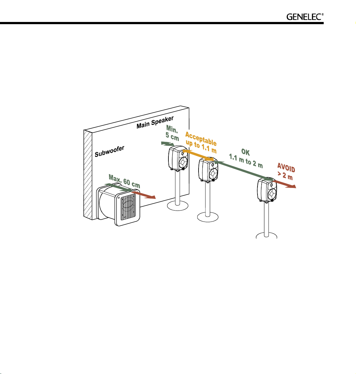
Recommended distances from a single wall to the front baffle of free-standing loudspeakers.
Correct (green), acceptable (orange) and not recommended (red).
Page 25
25
Subwoofer placement
Subwoofers can make life much easier in producing high quality low frequency reproduction. When a
subwoofer is used, the loudspeakers can be placed more freely, thereby allowing more flexibility in finding
a good location in the room for the reproduction of low frequencies.
A subwoofer should be placed close to a wall, preferably closer than 0.6 meters (2 ft.) from a wall. This
placement eliminates most possible cancellation sources and the subwoofer response remains flat and
well loaded.
Recommended distances from a single wall to the front baffle of loudspeakers combined with subwoofer(s).
Correct (green), acceptable (orange) and not recommended (red).
Using a subwoofer provides an additional crossover frequency (typically at 85 Hz). This makes placing
loudspeakers much easier. Acceptable distances extend to 1.1 m because of the low frequency cut-off
of loudspeakers. Loudspeakers may be placed 1.1…2 m without serious compromises due to the wall
behind the loudspeaker causing serious cancellation effects.
Although Genelec subwoofers provide accurate phase control at the crossover point, loudspeakers
should not be placed further than 2 m (7 ft.) from a supporting subwoofer. Larger distance differences may
cause tonal balance differences around the crossover frequencies due to loudspeakers and subwoofer(s)
exciting different room modes.
Page 26
26
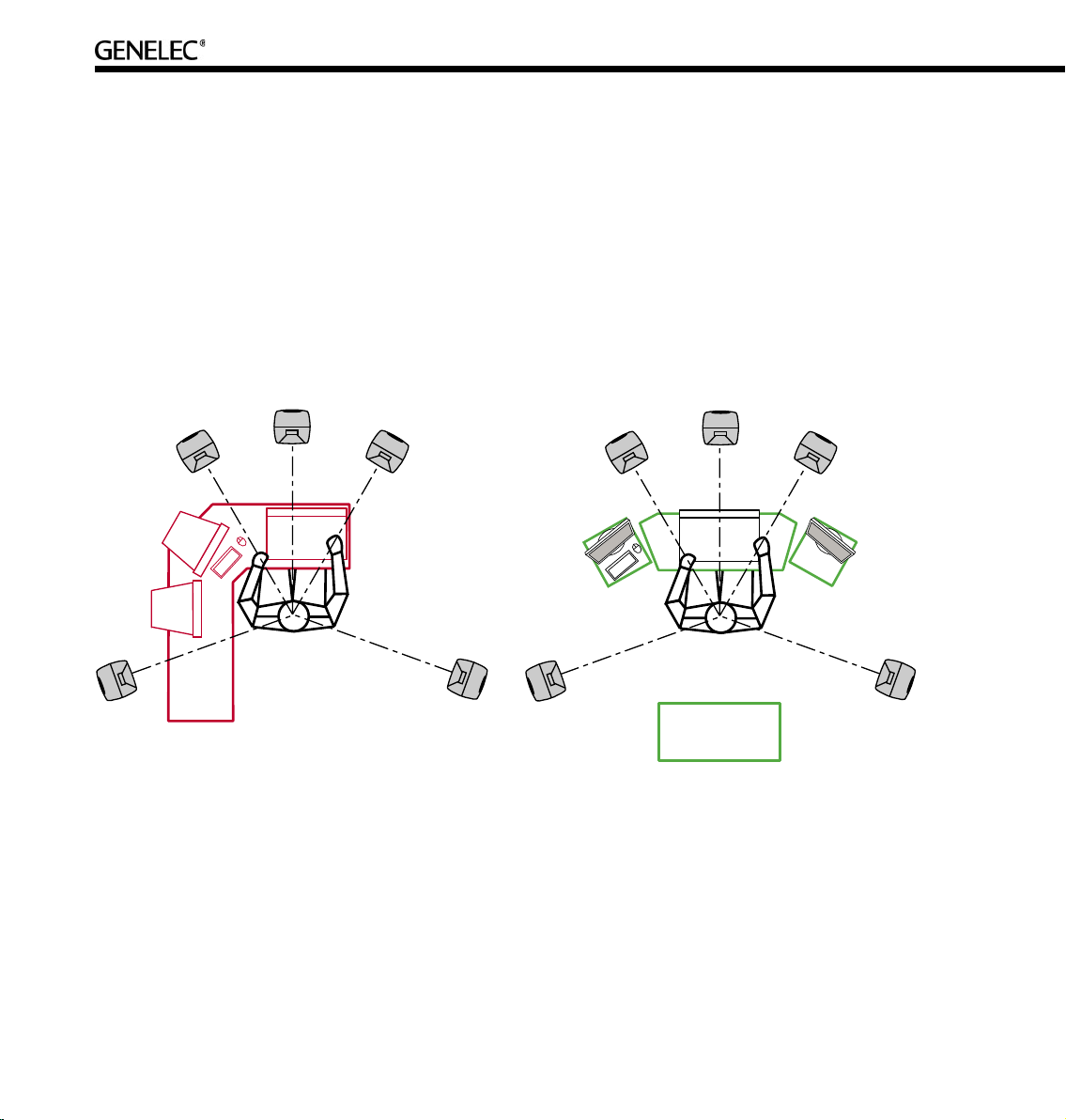
Multi-channel System Layout
The positioning of tables, screens, racks, etc, is critical in order to maintain accurate imaging. Early
reflections can smear the of the sound image and compromise localization. To avoid this, reflecting
surfaces between loudspeakers and the listening position should be minimized. Symmetrical positioning
of equipment is essential. Even with symmetry, reflecting surfaces should be removed from the vicinity
of acoustic paths.
Front loudspeaker, multi-channel layout. For multi-channel audio the Left and Right loudspeakers
should be placed 60 degrees apart, with the Center loudspeaker in the middle. All loudspeakers should
be of the same type so there are no coloration changes when panning sounds across the front stage.
Left figure: Example of non-symmetrical layout producing reflections from computer screens and
table surface totally different for different loudspeakers. This situation creates front-back and left-right
localisation smearing. Right figure: Symmetrical layout minimizes reflection surfaces and maintains
accurate localisation because reflections are similar due to symmetry.
Page 27
27
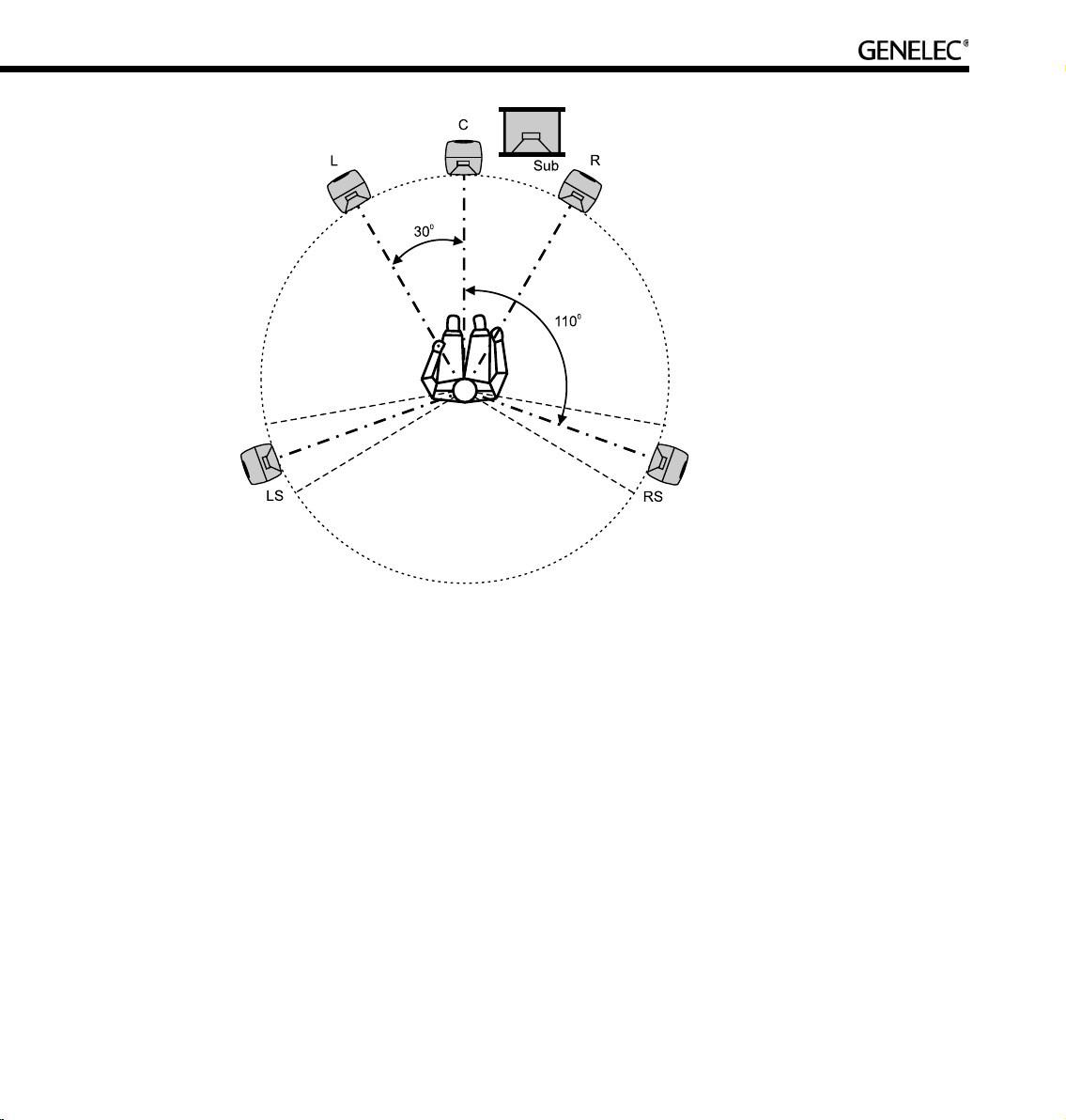
Recommended loudspeaker positioning for 5.1 multi-channel audio reproduction.
Surround loudspeakers. Surround loudspeakers should be placed in a positional window between
±100 to ±120 degrees from the centerline. If more than two loudspeakers are used an equal number of
loudspeakers should be placed symmetrically on both sides of the center line, on a circle between ±60 to
±150 degrees. Most recording engineers choose ±110…130-degree position for a surround stereo pair.
System location in room. It is important that the multi-channel installation is symmetrically located in the
room. Reflections created by boundaries should be identical from left to right so that spatial information
and panning of sources remains stable. It is also recommended that the listening position be located in
the front half of the room so that the direct sound level is maximized relative to the reverberant energy in
the room.
Aiming of acoustical axes. All loudspeakers should be aimed towards the engineer’s listening
position.
Page 28
28
GENELEC LOUDSPEAKER MANAGER GLM
Overview
The Genelec Loudspeaker Manager GLM is the control software for Genelec DSP loudspeaker systems.
The GLM runs on PC (Windows XP) and Macintosh (OSX) computer platforms.
The GLM knows which DSP loudspeakers are present on the control network and provides access to all
loudspeaker settings and system level controls.
The GLM is capable of controlling up to 25 main loudspeakers and 5 subwoofers and offers control of
everything within the loudspeaker system. This includes controls built into individual speakers as well
as full system controls including monitoring volume, mute/solo for audio channels, audio channel Group
selection and more.
All settings can be collectively stored into the computer as a System Setup File. Loading a System
Setup File recalls all system level settings and all settings inside each loudspeaker, including acoustic
calibration.
Using the GLM, all acoustic settings can also be stored into each loudspeaker for stand-alone use.
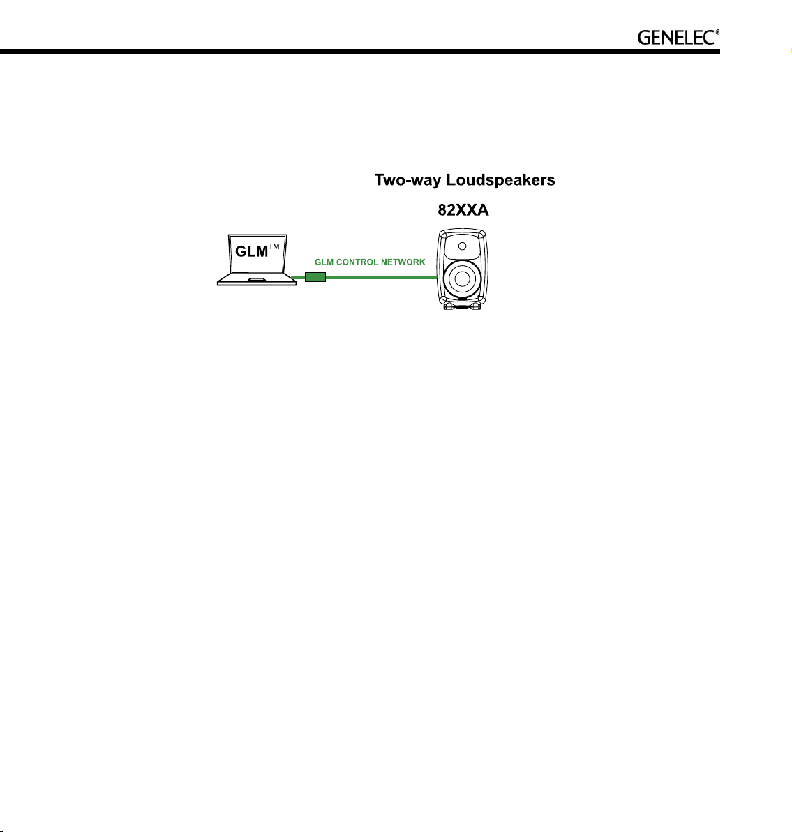
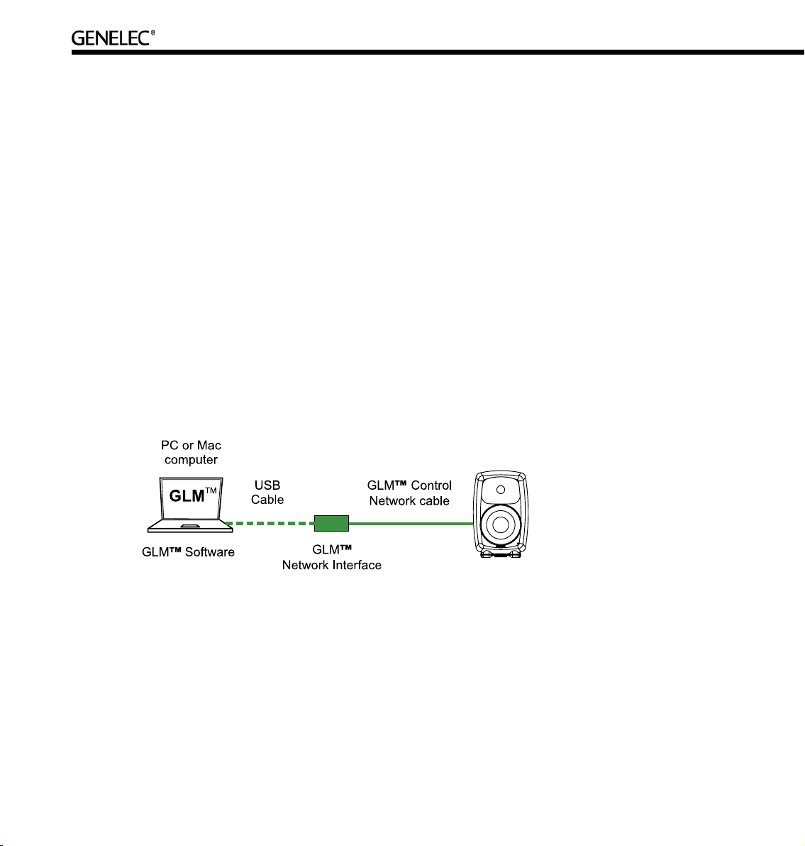
The basic structure of a GLM Control Network has the following components;
• Computer running the GLM software.
• One USB port of the computer connected to the GLM Network Interface.
• The GLM Network Interface.
• Network cable connected to all loudspeakers on the control network.
Page 29

29
GLM Control Network
GLM Network Interface
The GLM Network Interface serves as the communicator between all loudspeakers on the control
network and the computer. Attach the GLM Network Interface to a USB port. The device driver is installed
automatically.
The USB cable runs from the computer to the GLM Network Interface. Once the GLM Network Interface
is connected to the computer flashing lights on the interface indicate that the network is active. If no
communication lights are flashing, check that the control network cable and the USB cable are securely
attached and the GLM software is running.
The Genelec loudspeaker control network runs on CAT5 cables. These are the same cables that are used
for Ethernet. Instead of using Ethernet for communication with loudspeakers, Genelec uses a proprietary
protocol defining the method of communication, and the GLM Network Interface that connects to the USB
port on the computer.
There are several important reasons why a USB interface is used instead of, for example, the Ethernet.
This keeps the network running at all times, even if the computer crashes. The GLM Network Interface
acts as the master controller on the network, and communicates to all loudspeakers even if the computer
is rebooting.
The Genelec network uses a proprietary communication protocol to ensure integrity of communication
to and from loudspeakers. The GLM Network Interface is used as a translator between the Genelec
control network and any computer hardware using it. This ensures that loudspeaker control traffic
remains insulated and secured from any public networks. This is necessary because of the possibility of
congestion on public networks (loudspeaker control messages do not get through), and in order to limit
the range of access (outsiders on a public network could possibly control the loudspeakers).
The USB interface is ubiquitous in the computer world. A USB cable run is normally limited to 5 m (15 ft.),
but this is not a problem. The computer network cable from the GLM Network Interface can extend to any
practical distance needed. If the GLM Network Interface cannot be placed close the computer the USB
cable can be extended with actively buffered cables up to 25 meters (75 ft.) in length.
Page 30
30
Note
If the GLM Network Interface is disconnected or the computer is powered down, the GLM will no
longer control the loudspeakers. In that event, the loudspeakers maintain their current settings until the
loudspeaker is powered down.
When the loudspeakers are re-powered and the GLM software is not controlling the network, the loudspeakers obtain acoustic settings based either on the user interface controls on the loudspeaker (manual
controls) or from their internal memory (stored settings). This choice is determined by the position of
switch marked “STORED/MANUAL CTRL”.
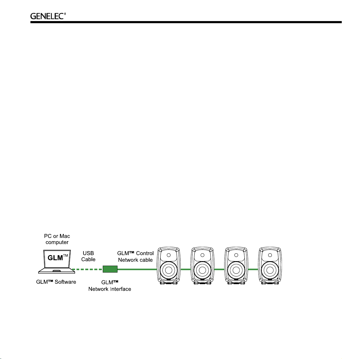
GLM Control Network Cabling
Control comes from the computer running the GLM software. The computer connects to the GLM Network
Interface via the USB port (a 1.5-meter USB cable is provided). The GLM Network Interface connects
onwards to all loudspeakers using network cable.
The GLM Control Network starts from the GLM Network Interface and connects to the first loudspeaker
(any one, just take a pick) and then onwards until all loudspeakers have been connected.
Each loudspeaker has two control network connections. One is used as the input and the other as the
output to the next loudspeaker. It does not matter in which order the loudspeakers are connected on the
GLM Control Network. On the last loudspeaker of the control network chain, only one of the two Genelec
control network connectors will be used.
Page 31

31
Consider an example with five two-way loudspeakers and one subwoofer. The digital audio uses AES/
EBU cabling where each physical audio cable carry two channels of digital audio. All audio cables run
to the subwoofer first and then to the two-way loudspeakers. The GLM Control Network starts from the
USB port of the system-controlling computer, runs through the GLM Network Interface and onwards to all
loudspeakers. Because the order in which loudspeakers are connected to the control network is free and
arbitrary, the control network cable was run conveniently in this example to two two-way loudspeakers,
then to the subwoofer and finally to the remaining three two-ways.
Page 32

32
GLM Control Network Size
Number of loudspeakers. The GLM Control Network can support up to 30 loudspeakers. All loudspeakers
should be in one room.
Control network length. The length of the GLM Control Network is calculated by adding up the entire
control network cable in the system. For example, six runs of 10-meter cables, gives a total cable length
of 60 meters (180ft.). If the total length of the network cable exceeds 300 meters (900 feet), contact the
local Genelec Distributor for solutions.
Buying Cables for the GLM Control Network
All Genelec DSP loudspeakers are supplied with one 5 m network cable. Additional or longer standard
high quality CAT5 Ethernet cable with PC-to-HUB (direct) wiring, can be purchased from a local computer
store. This is the normal wiring for a CAT5 cable. Note that the cable must be fully populated, that is, the
cable must have all eight pins in the connectors connected by wires.
Installing the GLM Software
Put the software CD in the CD-ROM drive of the computer. The installation will start automatically. Follow
the on-screen instructions.
Running the System Setup Wizard
The System Setup Wizard is a self-guiding program designed to make the installation process easy and
complete.
The basic flow of setting up the system is detailed below. Consult the sections of this manual mentioned
in each step for further details.
• Unpack and position the loudspeakers. See the “Loudspeaker Placement” section for details.
• Find the Genelec Control Network cables in each loudspeaker delivery box. Connect the control
network. See the “Genelec control network cabling” section for details.
• Find the GLM Network Interface Device and follow cabling instructions. See the “GLM Network
Interface Device” section for details.
• Find the software CD in the Genelec Loudspeaker Manager package, insert it in computer and
follow on-screen instructions to install Genelec Loudspeaker Manager GLM on the computer.
See the “GLM Genelec Loudspeaker Manager” section for details.
• Launch the GLM, then follow the on-screen instructions to complete a System Setup. Select
either Rapid Cabling Mode or Manual Cabling Mode and follow the instructions.
Page 33

33
• If there is no applicable Rapid Cabling Preset, select the Manual Cabling Wizard. See the “Manual
Audio Cabling” section for details. Plan all cabling according to the guidelines provided in this
section. Plan channel labeling and loudspeaker labeling and launch the Manual Cabling
Wizard.
• To acoustically align the system, run the Acoustic Setup Wizard in the GLM. See the “Acoustic Setup
Wizard” section for details.
• Use the fully automated alignment system AutoCal built into the Acoustic Setup Wizard.
• Finally Save the System Setup and study the basic use of the GLM.
Before running the System Setup Wizard, make sure that all audio source equipment output levels are
turned down.
Once the network cabling is complete, turn on all the loudspeakers. From the computer, launch the
Genelec Loudspeaker Manager by clicking on the Genelec Loudspeaker Manager icon.
Launching the GLM for the first time automatically starts the System Setup Wizard. The first screen to that
appears is the Loudspeakers Online counter. Check that the number of loudspeakers and subwoofers
displayed in the GLM is the same as the number of loudspeakers and subwoofers connected to the GLM
Control Network. If the numbers do not match, check the network cables and connections, and the mains
power to the loudspeakers and subwoofers.
Page 34

34
Click Next> to Continue.
An introduction to the GLM System Setup Wizard will be presented first. Click Run Wizard to start the
GLM System Setup Wizard.
Page 35

35
Selection of Wizard. The Rapid Cabling Wizard covers the most typical system applications and makes
system setup very fast. In situations where the system setup is not covered in the Rapid Cabling Presets,
the Manual Cabling Wizard allows great flexibility to cover complex system designs.
Running the Acoustical Setup Wizard
The GLM contains an Acoustical Wizard to help quickly align the loudspeaker system. The Acoustical
Wizard is separated into two sections.
Manual Use. To manually make changes to the loudspeakers select Manual and click Yes to start it.
Automated acoustical setup, AutoCal. To automatically align the loudspeaker system, select AutoCal
and click Yes to start it.
Page 36

36
BASIC USE OF THE GLM
The Genelec Loudspeaker Manager provides a versatile set of tools to operate the loudspeaker system.
For more details, study the section on the basic use of the GLM.
GLM Main Page
The Main Page of the GLM has the following primary functions:
• Volume functions (volume adjustment, volume presets, DIM, system mute)
• Bass management bypass
• Audio channel Group functions (group activation, solo and mute audio channels)
Page 37

37
Mute All and Bypass BM
In the upper left corner there are two system level controls. When activated, the background color of
these buttons will change to red.
The ‘Mute All’ button mutes the entire loudspeaker system. Other functions in the GLM may be operated
while Mute All in engaged. This control has an overriding effect, and any changes made elsewhere will
take effect once the ‘Mute All’ button is deactivated.
The ‘Bypass BM’ button offers control of the subwoofer’s bass management system.
• When the ‘Bypass BM’ button is engaged (red background), signals sent to the
loudspeakers are not filtered in the subwoofer bass management section and the low frequency
content in the signals remains intact.
• When the ‘Bypass BM’ button is disengaged (grey background), audio content below the
bass management crossover frequency are fed to the subwoofer and removed from the signals
sent to the loudspeakers.
Note that this is not a ‘subwoofer mute’ command. If there is an LFE channel (low frequency effects), the
subwoofer will reproduce the LFE channel even while the ‘Bypass BM’ is active.
Volume Control
The ‘Page Up’ and ‘Page Down’ buttons and the ‘Up’ and ‘Down’ arrow keys can be used to increment the
volume up or down in 0.5 dB steps. The mouse can also be used to increment the volume up and down
in 10 db steps by clicking on the volume fader.
A third-party USB physical volume controller knob (e.g. Griffin PowerMate ) can be used to adjust control
the volume, bass management bypass and mute functions. If the computer is located away from the
listening position, the USB knob can be placed up to 25 meters (75 ft.) away from the computer using
active buffered USB extension cables, or up to 5 meters (15 ft.) with passive USB extension cables.
Page 38

38
To the left of the volume fader there are three level preset icons. There are two ways to select a level
preset.
• Click the left mouse button on one of the green level preset icons placed on the left of the
system volume fader.
• Click the left mouse button on the level preset buttons in the ‘Preset Levels’ frame.
The DIM button reduces the system volume by -20 dB. When activated, the button color changes to red.
System volume and select volume presets are adjustable while the system DIM is active, but the actual
volume remains -20 dB below the value shown in the main window.
If the system has been calibrated for a Reference Level (Menu … Setup | Calibrate Reference Level), a
dB value will be displayed below the “DIM -20 dB” button.
The Reference Level is defined at the Primary Listening Position. Commercially released movies are
normally mixed at a reference level of 85 dB. Domestic broadcast and DVD releases are normally mixed
at a reference level of 79 dB. Music is mixed at whatever level the engineer prefers. The true or total
sound level depends of the actual number of loudspeakers playing and the program material fed into
them.
Level in dB
relative to digital
full scale
Level preset
icons
System
level
fader
Page 39

39
Clicking the ‘Show Fader Only’ button selects between the full view of the main window and a small
window showing only the level fader with the level preset icons.
Level Presets
The level preset section of the main window allows quick access to three preset sound levels.
The are two ways to set Level Presets.
• Enter a value into the ‘Preset Levels’ value box.
• Hold down the SHIFT key, locate the mouse pointer on one of the green level preset markers
to the left of the level fader and press down the left mouse button. Drag the icon to
the required level and release the mouse button.
Access to the GLM System Setup Editors
The ‘GLM System Setup’ button activates the System Setup Editor. This allows for changes to cabling,
groups and acoustical settings of the loudspeakers in the system. For further details about editing system
settings consult the System Setup Editor and Acoustic Setup Editor sections on this manual.
Select button to
activate a level
preset
Level preset
value
System DIM
button
Page 40

40
Information Data Banner
An Information Data Banner is located at the bottom of the screen and displays some useful data about
the current System Setup.
• Network status. The alternatives shown are ‘OK’ meaning that the control network is
running normally; ‘Check IF’ when the GLM is searching to find a network interface in one of the USB
ports on the computer; and ‘DEMO’ when GLM is run without the GLM Network Interface
connected.
• Type of audio cabling. The alternatives shown are ‘Analog’, ‘Digital (Single-Wire)’ and ‘Digital
(Dual-Wire)’.
• Number of loudspeakers seen by the control network. This field can be used to verify that all
loudspeakers are recognized on the network.
• Amount of Video Delay Compensation.
Audio Channel Group Functions
The right side of the Main GLM page provides some Group functions. The audio channels in the
loudspeaker system can be arranged into Groups, and clicking on the Group name activates a Group.
When a Group is activated, it opens and shows the audio channels belonging to this Group. Only the
channels belonging to the Group will play.
To the right of the audio channel names are the ‘Solo’ and ‘Mute’ buttons. By clicking on these buttons it
is possible to solo and mute one or more audio channels. The ‘Play All’ button resets any mute and solo
selections. Note that clicking ‘Play All’ does not turn the audio on if the ‘Mute All’ button is active.
Click on group
name to activate
the group
Turn all channels on
Mute this audio
channel
Solo this audio
channel
Page 41

41
Menu Items
The ‘File’ menu allows access to System Setup files.
• ‘File | New’ Starts the System Setup Wizard and is used to make a new setup from the
beginning.
• ‘File | Open’ Loading a System Setup File in the GLM automatically sets up all loudspeakers in the
system with monitoring group definitions, audio cable definitions, defaults for monitoring
levels and all acoustical alignment settings from a previously saved System Setup File.
• ‘File | Save’ stores all settings into the currently open System Setup file.
• ‘File | Save As…’ is used to save modifications in the current setup under a new System Setup
file name.
• Up to five recently used System Setup files are listed below ‘Save As’.
• ‘File | Exit’ closes the GLM.
• ‘Setup | Set GLM Startup Level’ reads and stores the current setting of the volume fader and
uses this volume setting when starting the GLM.
• ‘Setup | Calibrate Reference Level’ opens the Reference Level Calibration page.
• ‘Setup | Change Channel Order’ allows for changes to be made to the order in which audio
channels are listed in the Groups.
• ‘Setup | Password Protection’ allows for password protection of System Setup files. After setting
a password, a System Setup file can be opened but not saved without knowing the password.
This way, System Setups can be protected from unwanted tampering or alteration.
• ‘Setup | Acoustical Setup Wizard’ runs the Acoustical Setup Wizard for with the currently open
System Setup file. To create a new setup from scratch, select ‘File | New’ and then run the Rapid
or Manual Cabling Wizard and Acoustical Setup Wizard.
• ‘Setup | GLM System Setup Editor’ open the System Setup Page.
• ‘Setup | Store Acoustic Settings in All Online Loudspeakers’ permanently stores all Acoustical
Settings into all loudspeakers on the control network. Note that the Acoustical Settings defined in
Page 42

42
the currently open System Setup file are sent to all loudspeakers, but whenever a new System
Setup file is opened, all acoustic settings in loudspeakers will be written according to this new
System Setup file. Any Stored Settings will be available in Stand-Alone mode if the switch on
the loudspeaker back panel is set to the position “STORED CTRLS” and the GLM Control
Network is detached from the loudspeaker.
Page 43

43
RAPID CABLING WIZARD
How to Use Rapid Cabling
The Rapid Cabling Presets help speed up the System Setup by quick identification of the speakers and
reduced text entries. The most common loudspeaker setups seen in listening rooms have been included
with the Rapid Cabling Presets.
Table of Rapid Cabling Presets
Type of signal Audio
channel
layout
Rapid cabling option Support
for LFE
channel
Number of
subwoofer(s)
Analog 2.0 Stereo Pair No -
Analog 5.0 5.0 Surround System No -
AES/EBU single-wire 2.0 Stereo Pair No -
AES/EBU single-wire 2.0 Stereo Pair with Subwoofer No 1
AES/EBU single-wire 5.0 5.0 Surround System No -
AES/EBU single-wire 5.1 5.1 Surround System with Subwoofer Yes 1
AES/EBU single-wire 6.1 6.1 Surround System with Subwoofer Yes 1
AES/EBU single-wire 7.1 7.1 Surround System with Subwoofer Yes 1
AES/EBU dual-wire 2.0 Stereo Pair -
AES/EBU dual-wire 2.0 Stereo Pair with Subwoofer No 1
AES/EBU dual-wire 5.0 5.0 Surround System No 1
AES/EBU dual-wire 5.1 5.1 Surround System with Subwoofer Yes 1
Page 44

44
Here is a brief list of instructions on how to complete the Rapid Cabling Wizard.
• Before starting the GLM, identify in the Rapid Cabling Preset Table shown above, the description that
matches the desired loudspeaker setup. Then, find the corresponding section below and study
the cabling layout description and the AES sub-frame assignment table.
• At the sound source (mixing console, audio workstation, etc.) assign audio signals to the
AES/EBU outputs according to the table provided in each Rapid Cabling System Description.
• Connect audio cables according to the description and the cable wiring diagram in the Rapid
Cabling System Description.
• Connect the GLM Control Network cabling.
• Start the GLM and proceed to the System Setup Wizard. Select the Rapid Cabling Wizard.
Then select the Rapid Cabling System Preset in the drop-down box. At this point all the
loudspeakers should have a solid yellow light indicating that they are in standby mode.
• If the system is properly connected and loudspeakers turned on, the front panel light on one
loudspeaker will now be flashing and an ID Tone is briefly turned on. Select the label that
matches the loudspeaker with the flashing light. Once a match has been made press “Next”.
After the loudspeaker has been identified the flashing green light changes to a solid green light.
Repeat the procedure until all the loudspeakers have been identified.
• Press “Next”. The System Audio Connections page is shown. This provides a list of audio
channels and the loudspeakers that are connected to those channels. Press “Finish” if all entries
match.
• Use “File | Save As…” to name the System Setup that has just been created. Press “File | Save”
to save with the current name.
It is strongly suggested that the Acoustical Setup Wizard is now used to acoustically align the loudspeaker
system.
On the following pages each of the Rapid Cabling Presets are presented in more detail.
Page 45
45
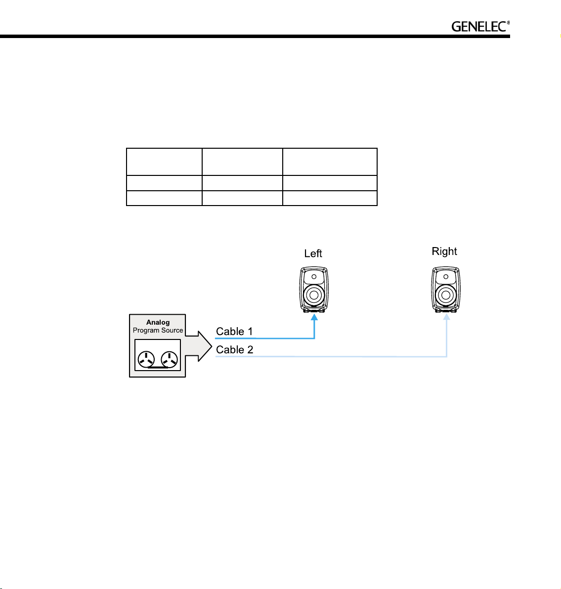
Stereo Pair Analog
Description. This Rapid Cabling Preset supports two analog audio cables. One carries the Left, the other
the Right audio channel.
Groups. There are three pre-assigned Groups: Stereo, Left, and Right.
Cable Number Audio Channel Loudspeaker input
connector
1 Left Analog in
2 Right Analog in
Page 46

46
5.0 Surround System Analog
Description. This Rapid Cabling Preset supports five analog audio cables. The five cables customarily
carry the Left, Center and Right Front channels and the Left and Right Rear channels.
Groups. There are three pre-assigned loudspeaker Groups: Surround, Stereo and Rears.
Cable number Audio channel Loudspeaker Input
Connector
1 Left Front Analog in
2 Right Front Analog in
3 Left Rear Analog in
4 Right Rear Analog in
5 Center Front Analog in
Page 47

47
Stereo Pair (AES/EBU Single-Wire)
Description. This Rapid Cabling Preset has one AES/EBU cable that carries both the Left and Right
audio channels.
AES/EBU sub-frame assignments. Sub-frame A should carry the Left audio channel. Sub-frame B
should carry the Right audio channel.
Cabling. Run one AES/EBU cable from the source to the digital audio inputs of the Left and Right
loudspeakers (the order is irrelevant).
Groups. There are three pre-assigned Groups: Stereo, Left and Right.
Cable number Sub-frame Audio channel Connector in
two-way loudspeaker
1 A Left Digital in
1 B Right Digital in
Page 48

48
Stereo Pair with Subwoofer (AES/EBU Single-Wire)
Description. This Rapid Cabling Preset has one AES/EBU cable that carries both the Left and Right
audio channels.
AES/EBU sub-frame assignments. Sub-frame A carries the Left audio channel. Sub-frame B carries
the Right audio channel.
Cabling. Run one AES/EBU cable from the source to the subwoofer, then from the output of the subwoofer
having the same number as the input to the digital audio inputs of the Left and Right loudspeakers (the
order of cabling the loudspeakers is irrelevant).
Groups. The pre-assigned Groups are Stereo, Left, and Right.
Cable number Sub-frame Audio channel Subwoofer Input
Connector
Loudspeaker Input
Connector
1 A Left AES/EBU input 1 Digital in
1 B Right AES/EBU input 1 Digital in
Page 49

49
5.0 Surround System (AES/EBU Single-Wire)
Description. This Rapid Cabling Preset utilizes three AES/EBU cables to carry 5.0 audio. “5.0” audio
refers to having five full-bandwidth audio channels and no LFE channel. No subwoofer is used.
AES/EBU sub-frame assignments. The AES/EBU digital audio cables are numbered one to three. The
AES/EBU sub-frame assignments and connectors to be used in two-way loudspeakers are provided in
the table below.
Groups. The three pre-assigned loudspeaker Groups are Surround, Stereo and Rears.
Cable number Sub-frame Audio channel Loudspeaker Input
Connector
1 A Left Front Digital in
1 B Right Front Digital in
2 A Left Rear Digital in
2 B Right Rear Digital in
3 A Center Front Digital in
Page 50

50
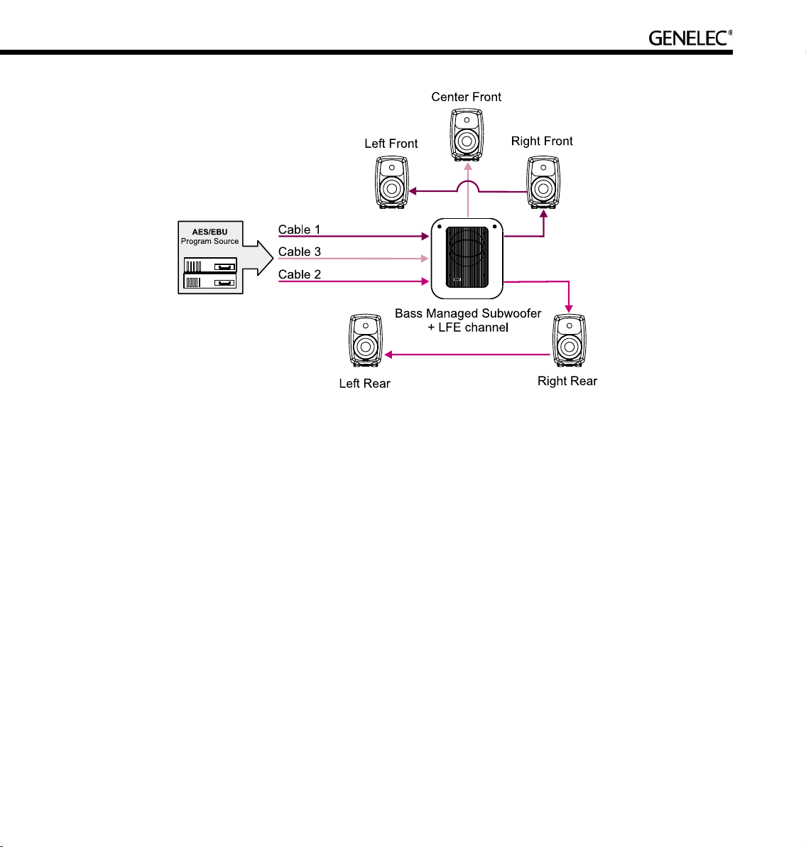
5.1 Surround System with Subwoofer (AES/EBU Single-Wire)
Description. This Rapid Cabling Preset utilizes three AES/EBU cables to carry 5.1-audio. “5.1” refers to
having five full-bandwidth audio channels and an LFE channel. All three cables run to the subwoofer first,
then from the subwoofer to the five loudspeakers.
AES/EBU sub-frame assignments. The AES/EBU digital audio cables are numbered one to three. The
AES/EBU sub-frame assignments and connectors to be used with the subwoofer and loudspeakers are
provided in the table below.
Cabling. Run three AES/EBU cables from the source to the subwoofer AES/EBU inputs 1, 2 and 4.
Subwoofer input number 3 is not used. Run the cables from the subwoofer AES/EBU outputs 1, 2 and 4
to the digital audio inputs of the loudspeakers. The cable that carries the LFE channel must be connected
to the subwoofer input number 4.
Groups. The pre-assigned Groups are Surround, Stereo, and Rears.
Cable number Sub-frame Audio channel Subwoofer Input
Connector
Loudspeaker Input
Connector
1 A Left Front AES/EBU Input 1 Digital in
1 B Right Front AES/EBU Input 1 Digital in
2 A Left Rear AES/EBU Input 2 Digital in
2 B Right Rear AES/EBU Input 2 Digital in
3 A Center Front AES/EBU Input 4 Digital in
3 B LFE AES/EBU Input 4 --
Page 51
51
6.1 Surround System with Subwoofer (AES/EBU Single-Wire)
Description. This Rapid Cabling Preset utilizes four AES/EBU cables to carry “6.1-audio”. “6.1” refers to
having six full-bandwidth audio channels and an LFE channel. All cables run to the subwoofer first, then
from the subwoofer to the six loudspeakers.
AES/EBU sub-frame assignments. The AES/EBU digital audio cables are numbered one to four.
The AES/EBU sub-frame assignments and connectors to be used with the subwoofer and two-way
loudspeakers are provided in the table below.
Cabling. Run four AES/EBU cables from the source to the subwoofer AES/EBU inputs 1, 2, 3 and 4.
Run the cables from the subwoofer AES/EBU outputs 1, 2, 3 and 4 to the digital audio inputs of the
loudspeakers. The cable that carries the LFE channel must be connected to the subwoofer input number
4.
Groups. The pre-assigned loudspeaker Groups are Surround, Stereo, and Rears.
Page 52
52
Cable number Sub-frame Audio channel Subwoofer Input
Connector
Loudspeaker Input
Connector
1 A Left Front AES/EBU Input 1 Digital in
1 B Right Front AES/EBU Input 1 Digital in
2 A Left Rear AES/EBU Input 2 Digital in
2 B Right Rear AES/EBU Input 2 Digital in
3 A Center Rear AES/EBU Input 3 Digital in
3 B Not used Not used --
4 A Center Front AES/EBU Input 4 Digital in
4 B LFE AES/EBU Input 4 --
Page 53

53
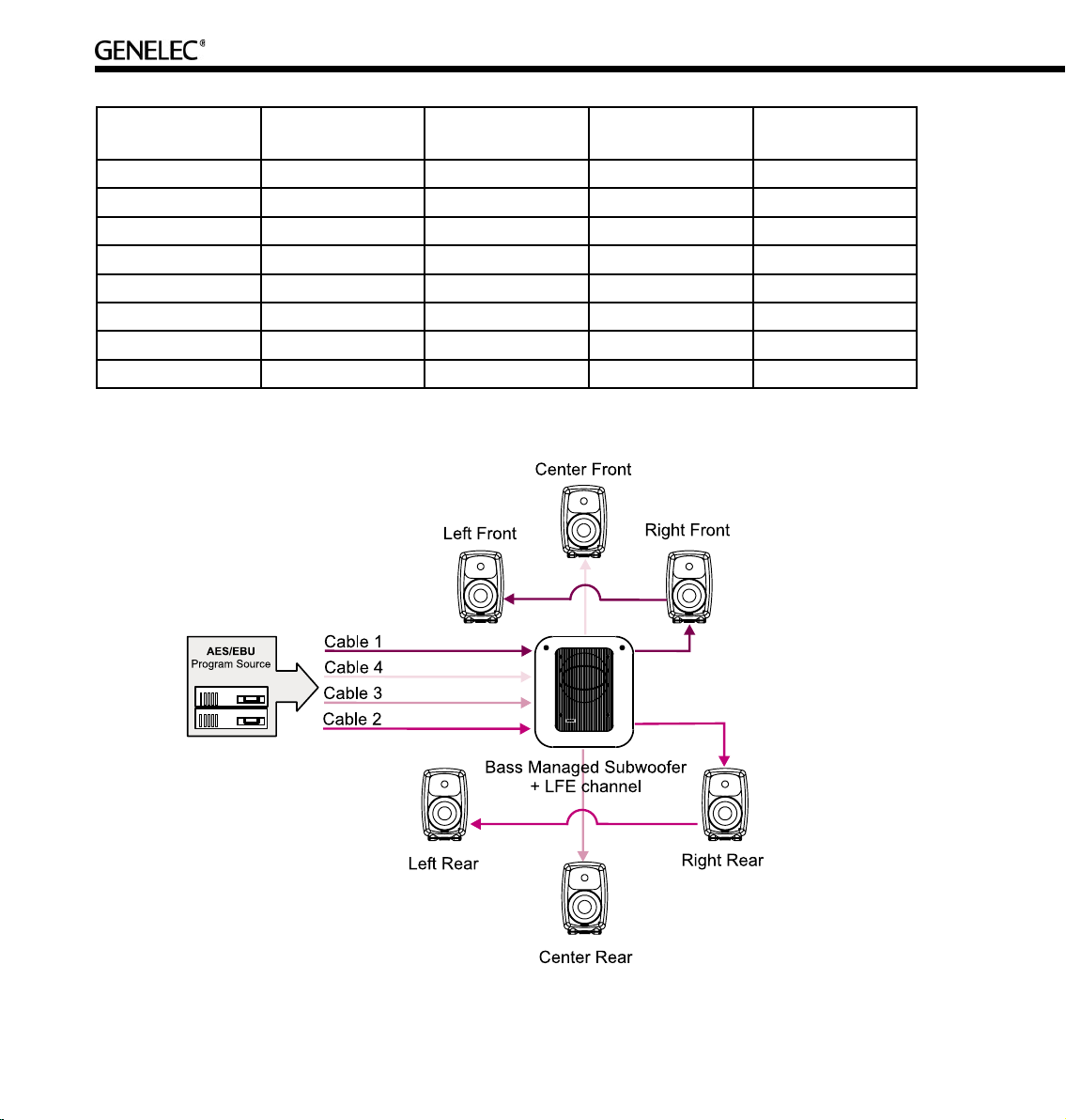
7.1 Surround System with Subwoofer (AES/EBU Single-Wire)
Description. This Rapid Cabling Preset uses four AES/EBU cables to carry “7.1-audio”. “7.1” refers to
seven full-bandwidth audio channels and an LFE channel. All cables run to the subwoofer first, then from
the subwoofer to the seven loudspeakers. In this system there are five loudspeakers in the front (Left
Front, Center Front, Right Front, Left Front Extra, and Right Front Extra), two loudspeakers in the rear
(Left Rear and Right Rear), and the LFE Low Frequency Effects channel reproduced by the subwoofer.
The AES/EBU digital audio cables are numbered one to four. The AES/EBU sub-frame assignments and
connectors to be used with the subwoofer and loudspeakers are provided in the table below.
Groups. The pre-assigned loudspeaker Groups are Surround, Stereo, and Rears.
Cable number Sub-frame Audio channel Subwoofer Input
Connector
Loudspeaker Input
Connector
1 A Left Front AES/EBU Input 1 Digital in
1 B Right Front AES/EBU Input 1 Digital in
2 A Left Rear AES/EBU Input 2 Digital in
2 B Right Rear AES/EBU Input 2 Digital in
3 A Left Front Extra AES/EBU Input 3 Digital in
3 B Right Front Extra AES/EBU Input 3 Digital in
4 A Center Front AES/EBU Input 4 Digital in
4 B LFE AES/EBU Input 4 --
Page 54

54
Stereo Pair (AES/EBU Dual-Wire)
Description. This Rapid Cabling Preset has two AES/EBU cables. Each carries one audio channel.
AES/EBU sub-frame assignments. This mode assumes the source uses the Dual-Wire mode of
transmission. In this mode the AES/EBU interface is operating at double speed (96 kHz) but consecutive
audio samples use both sub-frames resulting in a quad sample rate (192 kHz).
Cabling. Run one AES/EBU cable from the source to each loudspeaker digital audio input.
Groups. There are no pre-assigned Groups in this Setup.
Cable number Sub-frame Audio channel Loudspeaker Input
Connector
1 A+B Left Digital in
2 A+B Right Digital in
Page 55

55
Stereo Pair with Subwoofer (AES/EBU Dual-Wire)
Description. This Rapid Cabling Preset has two AES/EBU cables. Each carries one audio channel.
AES/EBU sub-frame assignments. This mode assumes the source uses the Dual-Wire mode of
transmission. In this mode the AES/EBU interface is operating at double speed (96 kHz) but consecutive
audio samples use both sub-frames, resulting in a quad sample rate (192 kHz).
Cabling. Run two AES/EBU cables from the source to the subwoofer AES/EBU Inputs 1 and 2. Run two
audio cables from the subwoofer AES/EBU outputs 1 and 2 to the digital audio inputs of the left and right
loudspeakers.
Groups. The pre-assigned Groups are Surround, Left, and Right.
Cable number Sub-frame Audio channel Subwoofer Input
Connector
Loudspeaker Input
Connector
1 A+B Left AES/EBU input 1 Digital in
2 A+B Right AES/EBU input 2 Digital in
Page 56

56
5.0 Surround System (AES/EBU Dual-Wire)
Description. This Rapid Cabling Preset supports five digital audio cables. The five cables customarily
carry the Left, Center and Right Front channels and the Left and Right Rear channels.
AES/EBU sub-frame assignments. This mode assumes the source uses the Dual-Wire mode of
transmission. In this mode the AES/EBU interface is operating at double speed (96 kHz) but consecutive
audio samples use both sub-frames, resulting in quad sample rate (192 kHz).
Groups. The pre-assigned Groups are Surround, Stereo, and Rears.
Cable number Sub-frame 5.0 system audio
channel
Subwoofer Input
Connector
Loudspeaker Input
Connector
1 A+B Left Front -- Digital in
2 A+B Right Front -- Digital in
3 A+B Left Rear -- Digital in
4 A+B Right Rear -- Digital in
5 A+B Center Front -- Digital in
Page 57

57
5.1 Surround System with Subwoofer (AES/EBU Dual-Wire)
Description. This Rapid Cabling Preset supports six digital audio cables. The six cables customarily
carry the Left, Center and Right Front channels and the Left and Right Rear channels and the LFE Low
Frequency Effects channel. The rear channels are not bass managed.
AES/EBU sub-frame assignments. This mode assumes the source uses the Dual-Wire mode of
transmission. In this mode the AES/EBU interface is operating at double speed (96 kHz) but consecutive
audio samples use both sub-frames resulting in a quad sample rate (192 kHz).
Groups. There are 3 pre-assigned loudspeaker Groups; Surround, Stereo, and Rears.
Page 58

58
Cable number Sub-frame 5.1 system audio
channel
Subwoofer Input
Connector
Loudspeaker Input
Connector
1 A+B Left Front AES/EBU Input 1 Digital in
2 A+B Right Front AES/EBU Input 2 Digital in
3 A+B Left Rear -- Digital in
4 A+B Right Rear -- Digital in
5 A+B Center Front AES/EBU Input 3 Digital in
6 A+B LFE AES/EBU Input 4 Digital in
Page 59

59
MANUAL CABLING WIZARD
Planning Audio Cabling
XLR connector pin assignments for analog signals
For analog applications, use high quality balanced twisted pair cable with a shield. Use XLR connectors,
where pin number one is connected to the shield of the cable, pin number two is designated as the inphase signal (commonly marked as +) of the analog interface, and pin number three is the inverted signal
(typically marked by -). This is sometimes known as a “pin 2 hot mic cable.”
XLR connector pin Cable Note
1 Shield Connect at both ends to the cable shield
2 Twisted pair wire 1 In-phase signal
3 Twisted pair wire 2 Inverted signal
XLR connector pin assignments for AES/EBU signals
For digital applications cables specifically designed to carry high-speed digital audio should be used.
This cable should have 110-ohm characteristic impedance. Do not use standard microphone cable as
described above. It is well known that microphone cables intended for analog signals do not have good
performance for digital audio applications. Using these could result in poor digital audio performance,
especially for longer cable runs. The audio format used on these cables is AES/EBU.
The inputs will sync for sample rates from 32 kHz to 192 kHz Single-Wire signals. The inputs will also sync
to 192 kHz Dual-Wire signals. Since AES/EBU audio is typically transmitted in audio channel pairs (Channel
A and B), connections will have to be made from one loudspeaker to another. This is accomplished via the
THRU connector on the back of the loudspeakers and the output connectors in DSP subwoofers. Typical
pairing in a two-channel stereo AES/EBU bit-stream has the Left audio channel carried in the AES/EBU
subframe A and Right audio channel carried in the AES/EBU subframe B. The digital audio cable can go
to either loudspeaker first. Select which subframe to reproduce by selecting Channel A or B in the GLM
software or, in case of stand-alone use, on the back panel of the loudspeaker.
MAKE SURE ALL AUDIO CABLES ARE LABELED
BEFORE STARTING THE CABLING PROCEDURE!
Page 60

60
It is suggested that the digital audio cables are labeled using with the following convention:
“AES/EBU Channel number and Subframe – Loudspeaker location.” For example: “AES/EBU 1A – Front
Left”
Analog cables should be labeled using a similar convention.
Stereo Setups
Digital audio cabling can go from source to either loudspeaker first, then on to the next loudspeaker using
the THRU connector. Freely connect to either loudspeaker first.
When using a 7200 series DSP subwoofer, all wiring MUST go to the subwoofer first, then to the pair of
loudspeakers.
Page 61

61
5.1 Multi-Channel Setup
A 5.1 multi-channel setup carries six channels of audio. They are the Left Front, Right Front, Center Front,
Left Rear, Right Rear, and LFE channels. The LFE channel is a bandwidth-limited low frequency effects
channel. To reproduce such a 5.1 setup, one subwoofer and five loudspeakers are normally used.
All digital audio cables must run to the subwoofer first. The 7200 series DSP subwoofers use AES/EBU
input number four as the LFE input.
Page 62

62
Duplicating Loudspeakers
It is also possible to daisy-chain digital audio signals to additional loudspeakers. One such application
might be a movie mixing room where multiple loudspeakers must reproduce the rear and side channel
signals.
In the example below the Left Rear and Right Rear loudspeakers have been duplicated. The system
is built simply by daisy-chaining the AES/EBU cable out from one loudspeaker to the next unit until all
loudspeakers have been connected. The GLM is then used to assign the correct audio channels to each
loudspeaker and to acoustically align the loudspeakers.
Page 63

63
Grouping
Some applications might need two sets of left and right loudspeakers, say a pair of 8240A’s as near field
monitors and a pair of 8250A’s in a mid-field position. Here, the engineer can use the Grouping functions
in the GLM to create Groups for quick selection between the different sets of loudspeakers.
Run an AES/EBU audio cable from the audio source first to the subwoofers(s) and then to the loudspeakers.
Using the GLM software, assign the correct audio channels to each loudspeaker. Then create Group
Definitions containing the nearfields with or without the subwoofer(s) and the midfields with or without the
subwoofer(s). The GLM then supports rapid switching between Groups.
The subwoofer should be the first loudspeaker in the chain for those loudspeakers requiring bassmanagement.
In the example below, the 8250A stereo pair is playing full-bandwidth audio only. The subwoofer is placed
in the audio cabling daisy-chain before the 8240As to enable the 8240As to be bass managed. The
subwoofer reproduces low frequencies for the 8240As.
Page 64

64
Running the Manual Cabling Wizard
The Manual Cabling Wizard can be used to create a new setup. This happens automatically or by selecting
the menu item “File | New” and then selecting in the appearing window the Manual Cabling Wizard.
The next screen to appear is the Signal Format selection page. This page is used to define and document
the type of audio signal in use.
Select either AES/EBU or Analog. There follows a walk-through assuming AES/EBU signals are used.
Click Next> to continue.
Page 65

65
AES/EBU Mode Selection wiring type. Once AES/EBU signals have been selected, this screen defines
the type of AES/EBU signal present in the cabling. There are two possible choices: Single-Wire Mode
(two audio channels in one cable) or Dual-Wire Mode (one audio channel in one cable).
In this example, the more typical Single-Wire AES/EBU cabling is used. This is also the default in the
GLM.
Click “Next>” to continue.
Page 66

66
Audio Cable Definition. Since the Wizard has been told this Setup will contain two channels of digital
AES/EBU audio per cable, this screen now displays the channels being carried on the two AES/EBU
audio sub-frames. These are marked as Channel 1A and Channel1B.
The example below shows the Left and Right channels being assigned to 1A and 1B respectively. Enter
the channel names into each text box and select the proper channel type. If the system has more than
two channels click “Create New Cable” until all the channels have been accounted for.
Click “Next>” to continue to the System Cable Summary.
Page 67

67
Next is a summary of the loudspeaker system cable and audio channel definitions. Click the “<Back”
button to move backwards to make changes or correct mistakes.
Click “Next>” to continue
Now the audio cable definitions are complete. Move on to describe connections in each loudspeaker.
Page 68

68
Subwoofer Connection. Assign AES/EBU cables to appropriate inputs on the subwoofer. Use the pulldown menus under the area labeled “Connected Cables” to match the cables to the appropriate inputs.
Under the area labeled “Channel Selections”, select the channels to bass manage by selecting the
appropriate boxes. These channels will now be marked with “BM” in the “Connected Cables” area.
Note that the LFE channel can only be connected to subwoofer AES/EBU input number 4.
Click Next> to continue
Page 69

69
Loudspeaker Connection. Now assign the AES/EBU cables for the loudspeakers. Use the pull-down
menus under the area labeled “Connected Cables”. Select the cable name matching the cable connected
to the input on the loudspeaker. Select the appropriate box for the channel in the cable this loudspeaker
is to reproduce. Repeat this procedure for each loudspeaker until all the loudspeakers in the system have
been labeled and cables matched to their respective inputs.
To confirm that the settings of the correct loudspeaker are being edited, click the loudspeaker
icon and an ID tone will be heard. Also, a green light continuously flashes on the loudspeaker
front panel to indicate it is selected.
Click “Next>” to continue to System Cabling Summary
Page 70

70
The System Audio Connections page displays channel labeling, cable connections, and all reproduced
audio channels. In case changes need to be made, click the “Back” button to return to the earlier
windows.
Click “Next>” to continue.
Page 71

71
Creating Groups. A Group enables rapid selection of a set of audio channels/loudspeakers.
To create a Group, type in a name in the text box and select/deselect the desired loudspeakers for the
Group by clicking on the loudspeaker icons.
Click “Add New Group” to create another Group. Up to 32 Groups can be created.
Click “Finish” to Save and complete the Manual Cabling Wizard.
Page 72

72
Saving the Setup
Automated saving. While running the GLM Wizards, a question may appear asking the user to save the
changes done up to that point. This allows for convenient and timely saving while running the Wizard.
At this point the user is asked to save the settings made so far into a System Setup file. To save the setup,
type in a name and click “Save”. Once the setup has been saved there is a choice to run the Acoustical
Setup Wizard or to proceed directly to the GLM Main Page.
The setup can also be saved manually at any time after a Wizard has been completed. To save into the
current setup, select the menu item “File | Save”.
To save a setup under a new name, select the menu item “File | Save As…”.
Page 73

73
MANAGING SYSTEM SETUPS
A system setup contains information about
• The loudspeakers in the system setup
• Type of audio signal cabling
• How the audio channels have been assigned in the cables
• The input and output configurations of each loudspeaker
• The acoustic settings for each loudspeaker
The System Setup is saved as a .glm file extension and by default is saved into the location c://Program
Files/Genelec/Loudspeaker Manager/Setups
A System Setup file is created as a result of running the System Setup Wizard. Acoustic settings can be
added in the System Setup file by running the Acoustic Wizard. It is possible also to manually edit the
settings by using the System Editor tools.
This section explains how to access and edit information in the System Setup files.
Saving and Recalling Setups
The basic way to save system setups is to use the GLM main window “File | Save” or “File | Save As…”
commands.
The basic way to recall system setups is the “File | Open” command.
Additionally, the GLM asks the user to save the settings into a System Setup file after changes have been
made in the system’s settings by using the System Setup Editor. A dialog for saving changes will appear
when this happens.
To create a System Setup file with a new name, use the “Save As…” menu item to save the setup. After
that, make the desired changes in this new System Setup file.
Page 74

74
Opening the System Setup Editor
Setups are edited using the GLM System Setup Editor. This can be opened from the GLM Main Page by
clicking the “Setup->GLM System Setup” menu item or by clicking the “GLM System Setup” button on
GLM Main Page.
The System Setup Editor is divided into three main areas to:
• Create, remove and edit the properties of audio cable definitions
• Create, remove and edit Group definitions
• Edit acoustical and input settings for loudspeakers or subwoofers
Editing Audio Cabling Definitions
Audio cables can be added, edited or deleted.
The “Add Cable” button creates a new cable definition in the system’s settings.
The “Delete Cable” button deletes the selected cable definition. Note that a cable that is in use cannot be
deleted. A cable is in use if some loudspeakers or subwoofers have been defined as being connected to
it.
Page 75

75
The “Edit Cable” button opens the cable definition editor page to edit the selected cable.
Editing Group Definitions
A Group is a set of audio channels playing simultaneously. Note that one or more loudspeakers may be
reproducing one audio channel, and one or more audio channels may be reproduced by one loudspeaker,
so it is important to understand that Groups are a collection of audio channels, not just Groups of
loudspeakers.
Groups can be added, copied, edited or deleted.
The “Add Group” button creates a new Group definition to the System Setup file. By default all channels
are active in the new Group.
Page 76

76
The “Copy Group” button creates a new Group definition to the System Setup file with the same content
as the currently selected Group definition.
The “Edit Group” button opens a Group definition editor for modifying the selected Group.
The “Delete Group” button deletes the selected Group. There must be at least one Group in a System
Setup file.
Page 77

77
The Group definition editor provides step-by-step instructions when creating a new Group definition. The
default setting when creating a new Group is that all audio channels are selected and all loudspeakers
are playing.
To modify the Group, click on the audio channel nametags. This excludes (marked by a red ‘x’) all
loudspeakers reproducing this audio channel. It is possible also click on the individual loudspeakers to
exclude them from reproducing this audio channel. This allows editing of reproduction Groups on the
audio channel or loudspeaker level.
Finally, click “OK” to accept the changes. A question will be presented about saving the modified Group
definition in the currently active System Setup file.
Page 78

78
Replacing and Removing Loudspeakers in a System Setup File
GLM supports a situation where one or more loudspeakers have changed. When one loudspeaker is
replaced with a new one, from the GLM point of view the old loudspeaker has disappeared and the new
loudspeaker has appeared, but it still does not belong to the currently defined system.
A loudspeaker is identified with a unique identifier number. This ID number is recorded in the System
Setup file. When the ID numbers recorded in the System Setup file do not match the ID numbers of
the loudspeakers on the GLM Control Network, the Replace/Remove tool must be used. Replacing a
loudspeaker with a new loudspeaker means that that the loudspeaker’s settings are written to the new
loudspeaker. This process is useful if a loudspeaker breaks and is temporarily replaced with a new unit, or
if the loudspeakers are regularly moved and there is no guarantee that each loudspeaker is always used
in the same place in various installations.
When there is a loudspeaker definition in the System Setup, but this loudspeaker is no longer found on
the network, it is moved to the bottom of the list and identified as an Offline Loudspeaker. When this
occurs, the GLM activates the “Replace/Remove” button at the bottom of the System Setup Editor page.
To replace/remove a loudspeaker
• Click the loudspeaker definition that no longer is associated with a loudspeaker on the network.
• Click the “Replace/Remove” button. This opens the replace/remove editor.
• In the Replace/Remove editor, displayed at the top, is the loudspeaker to be replaced. At the
bottom is a list of the available but unassigned loudspeakers.
• In the Offline Loudspeakers area, the loudspeaker model is shown along with its given name and
unique identifier number.
Page 79

79
This new
loudspeaker is not
part of the setup
This loudspeaker is
in the setup but is
no longer found in
the network
Initiation of the
loudspeaker
replacement
process
• To replace this loudspeaker with another one available on the network, click on a loudspeaker
listed in the bottom table titled “Loudspeakers (Online)”. The selected loudspeaker will flash its
front panel light and an ID tone will play.
• Before clicking “OK”, check that the “Remove and Replace with” option has been selected as the
“Action”.
• Click “OK” to perform the replacement. Repeat this for other loudspeakers requiring replacement
in the System Setup.
Page 80

80
To remove a loudspeaker definition in a System Setup file, enter the Replace/Remove Tool and remove a
loudspeaker definition from the System Setup file
• Check that the “Remove” option has been selected as the “Action”.
• Click “OK”. This completes the removal process.
Page 81

81
ACOUSTICAL SETUP WIZARD
After the Rapid Cabling Wizard has been completed, there is an option to run the Acoustical Setup
Wizard. The Acoustical Setup Wizard may also be accessed at any time from the Setup menu on the
main page. When run, two modes are presented – Manual and AutoCal.
Manual Mode. To manually define or edit loudspeaker acoustic settings, select “Manual” and click “Yes”
to start the Manual Acoustical Wizard.
AutoCal Mode. AutoCal is an automatic calibration system that uses a calibrated precision measurement
microphone, and is able to fully calibrate a multiple loudspeaker system. It is possible manually edit the
acoustic settings after running AutoCal using the Interactive Response Editor, which may be found in the
Acoustical Settings Editor. To run AutoCal, select “AutoCal” and click “Yes”.
Study the section Basic acoustic tutorial to understand the most important acoustical principles of placing
loudspeakers into a monitoring space and the best ways to optimize sound quality. It is important to note
that electronic alignment should not be used to fix problems due to inappropriate loudspeaker positioning
in the room or incorrect angling of cabinets. It is important to place and aim the loudspeakers correctly
BEFORE equalizing. In addition, it is generally better to solve acoustical problems in the room using
acoustical solutions rather than relying on electronic equalization.
Page 82

82
Loudspeaker Placement and Distance
To identify the current loudspeaker, an ID Tone is played when the “Loudspeaker Placement
and Distance” page appears. This maybe played again at any time by clicking the loudspeaker
icon button. Also the LED on the loudspeaker flashes green.
For the current loudspeaker, select from the pull-down menu an acoustical setting that best describes
how the loudspeaker has been placed in the room. “Free Field” (default) is suitable for loudspeakers
positioned away from nearby boundaries. “Wall” is suitable for loudspeakers positioned next to a solid
wall and “Corner” is suitable for loudspeakers positioned in a solid corner. For more details on correct
placement, see the section “Placing Loudspeakers in the Monitoring Room”.
In addition, “Desktop Compensation” can be selected if the loudspeaker has been placed near a large
reflecting surface such as a desktop or large-format console. For more information on the Desktop
Compensation setting refer to the Function Reference section.
Page 83

83
Finally, the distance of the loudspeaker from the primary listening position should be measured and a
value entered (default is 2.00 meters).
Click the “Next>” button to move through the remaining loudspeakers on the GLM Control Network.
Aligning Loudspeaker Levels
If there is more than one loudspeaker on the GLM Control Network the levels should be equalized. In the
“Lowest Level” page, turn the Test Signal ON by clicking the Test Signal button. Then click on each of the
loudspeakers shown in the table to play the test tone through each loudspeaker (the loudspeaker’s LED
flashes green). Using a sound level meter set to “C-weighted” and “Slow”, find the loudspeaker producing
the lowest level. Define this loudspeaker as the reference loudspeaker by selecting it before clicking
Next> to continue.
In the “Level Calibration” pages, the levels of the other loudspeakers are matched to the reference
loudspeaker. This results in a system where all the loudspeakers produce the same audio level at the
listening position.
Page 84

84
Toggle between the Reference Loudspeaker and the loudspeaker to be calibrated (selection in the
field marked as Calibrating Loudspeaker). Move the slider to match the level of the loudspeaker to be
calibrated to that of the reference loudspeaker. A sound level meter set to “C-weighted” and “Slow” is
recommended for this task. To turn the Test Tone OFF at any time, click the ON/OFF button. Proceed
through all loudspeakers in the setup by clicking the “Next>” button.
Page 85
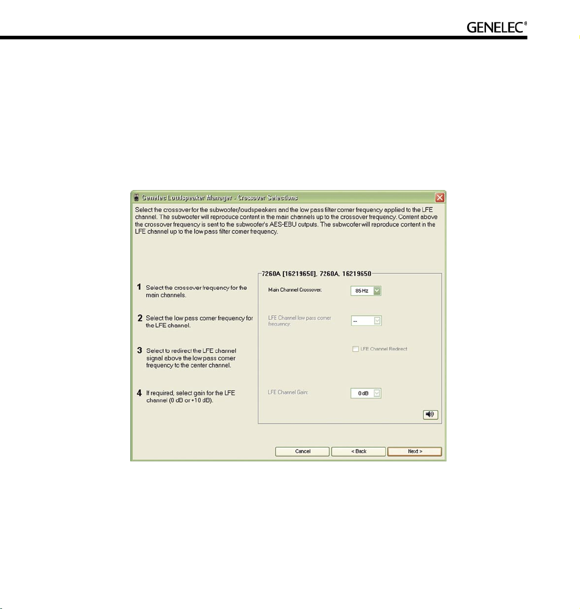
85
Setting Up Subwoofers
If there is a subwoofer on the GLM Control Network it should be calibrated. The “Crossover Selections”
page provides the opportunity to select a crossover for the main channels. If the setup has an LFE (Low
Frequency Effects) audio channel, appropriate LFE settings should be selected too. These include LFE
channel low pass filter corner frequency, LFE gain, and LFE re-direct.
NOTE: LFE controls are only available if an LFE channel was specified in the Audio Cable Definitions
portion of Manual Cabling Wizard or if a preset containing an LFE channel was selected at the start of the
Rapid Cabling Wizard.
The LFE controls allow the adjustment of the low pass corner frequency for the LFE audio channel. Then,
by using the LFE redirect, to redirect the LFE signal frequencies above the corner frequency into one of
the full-bandwidth audio outputs in the subwoofer.
Page 86

86
Main channel crossover: This control allows the crossover frequency for the full bandwidth (main)
audio channels to be chosen. It is recommended that the crossover frequency is set to 85 Hz (default).
The reasons are mainly acoustic and relate to typical listening conditions. This value is a good trade-off
between the following factors:
• Loudspeakers are to produce the highest output sound level with low distortion by removing the
very low frequencies in their signal feed.
• Loudspeakers couple less to modal resonances in the room thereby improving audio quality.
• Integration of the subwoofer(s) to the rest of the system is better when the subwoofer does not
produce high bass frequencies.
Conversely, there may be good reasons to select a higher or lower crossover frequency, but it is
recommended that good quality acoustical measurements are conducted before adjusting this control.
LFE channel low pass corner frequency: A low pass corner frequency of 120 Hz is recommended
for the LFE channel input as this is a widely accepted industry standard. There may be reason to select
another low pass corner frequency for certain applications.
LFE channel redirect: LFE channel redirection defines how audio content above the LFE channel low
pass corner frequency is handled.
If LFE redirection is not selected, audio content on the LFE channel above the “LFE channel low pass
corner frequency” is not reproduced. This is useful for “pre-filtering” the LFE channel. It is recommend that
mixes are checked with an 80 Hz pre-filter on the LFE to ensure uniformity of reproduction by different
consumer and professional processors.
If LFE redirection is selected, audio content in the LFE channel above the “LFE channel low pass corner
frequency” is redirected to another loudspeaker. This allows all audio content in the LFE content to be
heard. The LFE audio signal is filtered at the frequency set in the “LFE channel low pass corner frequency”
and so it is recommended that this control set to 85 Hz or less. In the subwoofer, content above this
frequency is summed to the other AES/EBU channel of Output 4 (AES/EBU single-wire mode) or to
Output 3 (AES/EBU dual-wire mode). It is recommended that the appropriate subwoofer AES/EBU output
(3 or 4 depending on wiring mode) is connected to a center loudspeaker. This results in the subwoofer
reproducing audio content below the “LFE channel low pass corner frequency” and center loudspeaker
reproducing the audio content above the “LFE channel low pass corner frequency”.
LFE channel gain: The correct value for this control depends on the audio source. Select “+10 dB” if the
audio source outputs the LFE channel at the same level as the main channels. This results in the LFE
Page 87
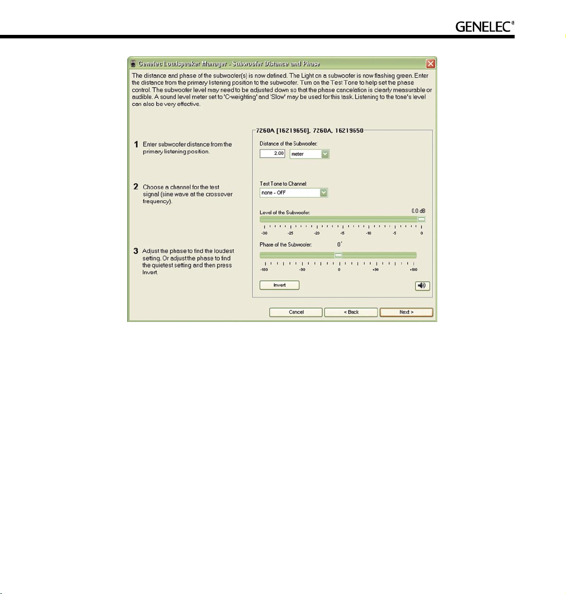
87
channel’s audio being boosted by 10 dB in the subwoofer. If the audio source already outputs the LFE
audio 10 dB higher than the main channels, select “0 dB”.
Click Next> to continue.
Subwoofer distance and phase: This defines subwoofer distance as well as set the subwoofer phase
at the crossover frequency.
Enter the physical distance of the loudspeaker measured from the primary listening position.
Calibration of phase at the crossover frequency is done by sending a tone generated by the subwoofer at
the crossover frequency into both the subwoofer and the selected loudspeaker. It is recommended that
the left or right loudspeaker is used in a two-channel system and that the center loudspeaker is used in a
multichannel system. Once the phase is set for the selected subwoofer/loudspeaker combination, other
subwoofer/loudspeaker combinations in the system may be checked
Page 88

88
The subwoofer phase is adjusted until the minimum level (maximum cancellation) of the test tone is found
at the primary listening position. This can be measured using a sound level meter set to “C-weighting” and
“Slow” or simply by listening. Then, to set the subwoofer exactly in phase, the phase is flipped 180-deg
using the “Invert” button.
Click Next> to continue.
When the settings have been made for all the loudspeakers on the GLM Control Network, a “Calibration
Summary” table containing the level alignments, distances and delays for each loudspeaker is
presented.
Click “Finish” to complete the Acoustical Setup Wizard and a question asks whether the acoustic settings
should be saved in the System Setup File. “Yes” saves the settings, “Cancel” allows changes to be made
to the settings, “No” discards the settings. The Main Page screen is now displayed and the GLM is ready
for use. To further edit a loudspeaker’s acoustical settings see Editing Acoustical Calibrations Manually.
Page 89

89
AUTOCAL – FULLY AUTOMATED SYSTEM CALIBRATION
Theory of Operation
AutoCal uses self-generated test signals and a high quality calibration microphone to find the correct
acoustical alignments for all the loudspeakers and subwoofers on the GLM Control Network.
AutoCal uses a sine tone sweep generated by each loudspeaker and subwoofer. This sweep is recorded
using a calibrated Genelec 8200A Calibration Microphone, over one or more positions, and the impulse
response calculated. AutoCal then determines the correct acoustical settings for each loudspeaker and
subwoofer to obtain:
• Flat frequency response at the listening position, or over an area.
• Equal delay from all loudspeakers to the primary listening position.
• Proper alignment of the subwoofer(s) in terms of output level and crossover phase (referenced
to a selected loudspeaker).
When AutoCal has optimized the Room Response Control settings the results can be saved into the
System Setup file. Further adjustment is then possible using the Acoustical Settings Editor.
AutoCal is an acoustical measurement system, so do not move around, talk or stand close to the
microphone when the measurements are being performed. A five second delay countdown starts from
the moment the “P” button is pressed until the first sweep tone is emitted. AutoCal is not designed
to compensate for poor room acoustics and/or poor loudspeaker positioning. These issues should be
addressed before using electronic equalization.
Page 90

90
Setting up for AutoCal
To set up for AutoCal:
• Place the Genelec 8200A Calibration Microphone on a microphone stand using the microphone
holder supplied in the GLM DSP Loudspeaker Manager Package. This holder positions the
microphone at the correct angle and mechanically decouples the microphone from the stand.
• Connect the microphone’s cable to the “MIC IN” socket of the GLM Network Interface.
• Connect one end of the 3.5 mm Measurement Signal Cable to the “MIC OUT” socket of the GLM
Network Interface and the other end to the microphone input of the computer’s sound card.
• Using the USB Cable, connect the computer to the GLM Network Interface.
• Attach a Network Cable, connected to the rest of the GLM Control Network, to the GLM Network
Interface.
The AutoCal uses the default sound card in the GLM computer and the line input or microphone input that
has been defined in the Windows Control Panel settings. Ensure that the input where the measurement
microphone signal has been connected is selected as the input in the Windows Control Panel.
This can be found in the Control Panel, Sound and Audio Devices, select ”Audio” tab, in the Sound
Recording frame, click on the ”Volume...” button. This opens the ”Recording Control” window. Ensure that
the correct input has been selected. The use of a line input is recommended. However, all computers do
Page 91

91
Page 92

92
not have a line input even if a line input is shown in the Recording Controls window. In that case you must
use the microphone input, and select the microphone input in the Recording Controls window. AutoCal
will automatically set the correct Volume setting for this input.
Running AutoCal
AutoCal can be run at the end of either Cabling Wizards. or from the GLM Main Page menu “Setup | GLM
Acoustic Wizard”.
When the Acoustical Wizard Mode Selection window appears, select “AutoCal” and press “OK”.
The AutoCal process consists of two main stages; firstly the acoustic responses of the loudspeakers and
subwoofers are measured, secondly the loudspeakers and subwoofers are aligned for flat response,
equal delay and level. Below is a more detailed description of what happens and needs to be done by
the user:
• Connect all the cables as described above. Connect the “MIC OUT” of the GLM Network Interface
to the line input of the computer soundcard. Make sure not to connect to the headphone
output in the computer!
• Type the serial number printed on the side of the Genelec 8200A Calibration Microphone into the
“Microphone Serial Number” box. This retrieves the calibration file for that microphone.
Page 93

93
The calibration file corrects for small frequency response and sensitivity differences between
microphones.
• Before starting the measurements, decide whether only the primary listening position is to be
measured (SinglePoint measurement) or whether additional measurement positions (MultiPoint
measurement) will be used.
Note: Spatial averages generally show less variation than a single point measurement, therefore less
equalization will be applied. This is useful if there is a listening area rather a single well-defined listening
point. The primary listening position measurement constitutes 50% of the MultiPoint response and the
sum of the other measurements makes up the remainder. This biases the results towards the center of
the listening area.
• Position the microphone at the primary listening position (normally the center of the mixing
console) and press the button labeled “P” (brown color).
• Before the loudspeaker measurements begin, AutoCal automatically compensates for the
response of the input stage of the soundcard. This is done to ensure that the frequency response
Page 94

94
of the microphone input does not affect the acoustic measurement results. It only needs to be
done once, when AutoCal is first run.
• Next, all the subwoofers and loudspeakers will be measured one at a time.
• If this is a MultiPoint measurement, move the microphone to a new position, press one of the
numbered buttons and another set of measurements will be taken. Up to 3 optional positions
can be measured in this way. The additional points may be measured in any order. Any number
of additional points up to three may be measured.
• Once the measurements have been completed, press the “Calculate” button to optimize
the Room Response Controls in each subwoofer and loudspeaker. The measurement
taken at the primary listening position constitutes 50% of the frequency response to be optimized.
The remaining 50% is the sum of the MultiPoint measurements. Delays and levels are based on
the primary measurement.
• After optimization, the result for each loudspeaker and subwoofer can be reviewed in the graph
shown below. The response of each loudspeaker may be viewed by clicking on the loudspeaker
name in the Loudspeaker List.
• Finally press the “Finish” button and decide whether to save the results to the setup file,
press the “Yes” button, or discard them, press the “No” button. New acoustical settings will
be immediately set in all loudspeakers and subwoofers.
Subwoofer Phase Aligment using the AutoPhase
The AutoPhase automatic subwoofer phase calibration process can individually select the optimal phase
alignment setting for each subwoofer in the loudspeaker system for a specified crossover frequency and
reference loudspeaker. The optimal phase alignment results in the best flatness of the acoustic response
within the subwoofer-to-loudspeaker crossover region.
For optimal performance, the AutoPhase process should be rerun every time the crossover frequencies
for the subwoofers are changed. Also, if you change the subwoofer Distance value in the Acoustical
Settings Editor for Subwoofer, the AutoPhase process must be rerun for best performance.
Please note that when you run AutoCal for the entire loudspeaker system, the option to run AutoPhase
is also available.
In order to run the subwoofer phase calibration process, the measurement microphone must be connected
to the computer using the GLM network interface, and the microphone must be placed at the primary
listening position.
Page 95

95
AutoCal uses the default sound card in the GLM computer and the line input or microphone input that
has been defined in the Windows Control Panel settings. Ensure that the input where the measurement
microphone signal has been connected is selected as the input in the Windows Control Panel.
This can be found in the Control Panel, Sound and Audio Devices, select ”Audio” tab, in the Sound
Page 96

96
Recording frame, click on the ”Volume...” button. This opens the ”Recording Control” window. Ensure that
the correct input has been selected. The use of a line input is recommended. However, all computers do
not have a line input even if a line input is shown in the Recording Controls window. In that case you must
use the microphone input, and select the microphone input in the Recording Controls window. AutoCal
will automatically set the correct Volume setting for this input.
To access the automatic subwoofer phase alignment or AutoPhase, enter the Acoustic Wizard, select the
AutoCal, and click ”Yes”. This opens the AutoCal window presenting a five-point process of automatic
calibration. To directly access the AutoPhase, find step number five, ”Run AutoPhase”, and click the
”AutoPhase” button.
This opens the AutoPhase window, presenting a list of subwoofers on the control network. For each
subwoofer, select in the drop down boxes the Crossover, Channel, and Loudspeaker.
The Crossover defines the crossover frequency for the subwoofer. It is possible to select individual crossover
Page 97

97
frequencies for each subwoofer, if this is necessary due to acoustical reasons. It is recommended that the
same crossover frequency is used for all subwoofers.
The Channel is the audio output channel for the test tone in the subwoofer. The loudspeaker must be
connected to reproduce this audio channel, and the audio cable must be connected from the subwoofer
to the loudspeaker. The Loudspeaker is the reference loudspeaker for subwoofer phase alignment. One
of the loudspeakers connected to the subwoofer is selected as the reference loudspeaker.
After crossover frequencies and reference loudspeakers have been defined for all subwoofers, click the
”Calibrate” button to start the AutoPhase process.
When the calibration process is running, a test tone is switched on by the GLM, and the microphone signal
is recorded and analysed. The calibration process for each subwoofer is graphically indicated. All noise or
other audio signals should be avoided during the calibration process, while the test tone is playing.
Editing AutoCal settings manually
Once AutoCal measurements have been taken, they become available in the GLM Acoustic Editor. A new
button will appear under the graphic presentation of the equalizer response.
Clicking the “Interactive Response Editor” button opens a new window, the Interactive Response Editor.
This window now shows the response measured by AutoCal, the correction and the corrected acoustic
response. This view is interactive and will immediately respond to changes in the controls on the Acoustical
Settings Editor page. Manually editing the numbers in the Room Response Controls section on this
page will change the correction in the loudspeaker. The same can be affected by pulling any controls
on the interactive filter response display. Also, any changes in filtering are immediately audible in the
loudspeaker. This way it is possible to manually edit the equalization created by AutoCal.
Click “OK” in the Acoustical Settings Editor to save the edited settings in the System Setup File.
Storing settings permanently into loudspeakers
The Acoustical Settings determined by AutoCal are not automatically uploaded to the memory inside the
loudspeakers and subwoofers. They are saved in in the currently open System Setup file.
If the GLM is used to control the system, it is not necessary to store the Acoustical Settings determined by
AutoCal into the loudspeakers and subwoofers. Opening a System Setup file fully restores all Acoustical
Settings in a system.
Page 98

98
If the GLM is not used to control the system, the loudspeakers will be working in the stand-alone mode. For
stand-alone use, the Acoustical Settings determined by AutoCal should be written into the loudspeakers
and subwoofers. This is achieved by selecting the Main Page menu item “Setup | Store Acoustic Settings
to All Online Loudspeakers”.
Storing the Acoustical Settings inside the loudspeakers’ memory is a very effective way of performing full
system calibration for a stand-alone Genelec DSP loudspeaker system. Use AutoCal to determine the
system calibration, store the settings permanently in the loudspeakers and then remove the GLM Control
Network. One computer running GLM can be used to set up any number of systems, for example a multiroom studio or broadcast facility. The settings for each system can be stored in different System Setup
files and so are readily available should the system need to be reinstalled or maintained in some way.
One example of such maintenance is if a loudspeaker fails. Simply replace the loudspeaker and rewrite the
system setup into the loudspeakers on the GLM Control Network. Another example is where loudspeaker
systems may be warehoused and called out for use in one of several rooms. The loudspeakers must
be re-assigned for this to succeed, i.e. the correct serial number must be found or serial numbers in the
system setup file must be swapped to the serial number of loudspeakers actually existing on the GLM
Control Network. This process is explained in the section ‘Replacing Loudpseakers.’
Page 99

99
EDITING ACOUSTIC CALIBRATIONS
The GLM contains a versatile set of controls to edit the acoustic setup of a loudspeaker or subwoofer.
Changing these acoustical controls is strongly discouraged unless there is access to a properly set up
professional acoustic measurement system, for example, MLSSA or WinMLS. Adjusting the acoustic
calibration “by ear” will most likely result in a degradation of audio quality.
Opening the Acoustical Settings Editor
The Acoustical Settings Editor can be accessed as follows:
• In the GLM main window, click the “GLM System Setup” button, or select the menu item
“Setup | GLM System Setup”.
Page 100

100
• Now select a loudspeaker in the “Loudspeakers (Online)” pane seen in the lower half of the
System Setup window.
• Click the “Edit Acoustic Settings” button or double click on loudspeaker (loudspeaker column)
and the “Acoustical Setup” will open for that loudspeaker. Note that the appearance of the
Acoustical Setup Editor window depends on the loudspeaker type.
Two-Way Loudspeakers
The Acoustical Settings Editor for a two-way loudspeaker looks like this:
It contains the following functionality:
• Room Response Controls: Provides access to the controls inside the loudspeaker that affect the
frequency response. These are a versatile set of controls especially designed for in-situ
loudspeaker equalization.
• Level and Distance controls: Allows for alignment of this loudspeaker into a system of
loudspeakers.
 Loading...