

Page 1
AIC25
Operating Manual
Genelec AIC25
Active In-Ceiling Loudspeaker
Page 2
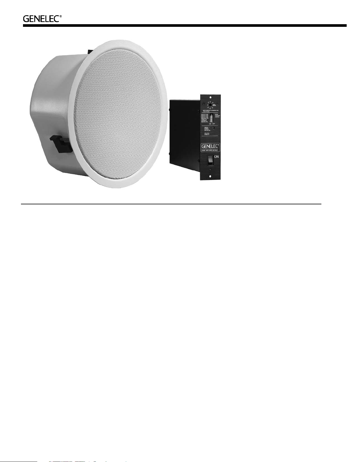
Genelec AIC25 Active In-Ceiling Loudspeaker
The Genelec AIC25 Active In-Ceiling loud-
speaker system consists of a two-way
loudspeaker enclosure and a matched
remote amplifier module, RAM2. It has been
designed to the same rigorous standards
as Genelec’s high-perfor mance HT ser ies
active Home Theater loudspeakers. No other
In-Ceiling loudspeaker in this size class can
match the low distortion, neutrality and high
sound pressure capability of Genelec AIC25.
Unpacking
A Genelec AIC25 set includes the following
items. Check that nothing is missing or dam-
aged in transit. If there is a problem with the
product, contact your local Genelec dealer.
• AIC25 loudspeaker enclosure.
• Grill insert
• AIC25 cardboard cut-out template
• Loudspeaker painting mask
• RAM2 amplifier unit
• Mains power cable
• Two M4 Phillips 2 screws
• This Operating Manual
Installation
Genelec recommends that you use the serv-
ices of an authorized installation specialist or
other competent and experienced installa-
tion company for the installation of the AIC25
system. Ask your local Genelec dealer for
recommended installation companies in your
region.
Matching loudspeakers and
amplifiers
Each AIC25 loudspeaker has been factory
calibrated for optimum performance with the
RAM2 amplifier it is shipped with. Never mix
these matched amplifier-loudspeaker sys-
tems in the installation process. The matching
units are marked with the same ID number.
Cabling
The RAM2 amplifier unit has separate power
amplifiers for the tweeter and woofer. Accord-
ingly, a 4-conductor cable needs to be run
between the amplifier and the loudspeaker
enclosure. Two cable connectors are sup-
plied with the loudspeaker system, a six-pole
connector to fit the connector on the amplifier
and a four-pole connector to fit the respective
input on the top of the loudspeaker enclo-
sure.
Attach the cables to the green connectors
provided with the kit. Be sure to maintain cor-
rect polarity when connecting the cables and
be extra careful not to mix the tweeter and
woofer cables. The correct pin sequences
are marked on the amplifier and loudspeaker
enclosure. Starting from the top, the first two
poles on the amplifier connector are for the 12
V remote control voltage, pole 3 for tweeter -,
pole 4 for tweeter +, pole 5 for woofer - and
pole 6 for woofer +. Respectively, the pole
sequence on the loudspeaker connector is
1 tweeter -, 2 tweeter +, 3 woofer - and 4
woofer +. Secure the cable to the strain relief
tie next to the loudspeaker connector.
Use a good quality 4-conductor cable and
make the cable runs as short as possible.
See Table 1 for recommended cable gauges.
The connectors accept a cable up to 6 mm
(9 gauge) thick.
If you are installing the AIC25 enclosure
to an existing construction, examine the
ceiling thoroughly for the shortest and least
obstructed cable route. Be careful to avoid
cutting or drilling into electrical wires, venti-
lation or water pipes. All of this is of course
much easier when the installation takes place
in an unfinished building where the ceiling
structure is still open. In both cases it is a
good idea to route the loudspeaker cables
away from electric, video or phone cables,
which might induce hum into the loudspeaker
system.
2
Page 3

Figure 1. RAM2 amplifier back panel view
Figure 2. Connecting the loudspeaker cable
Figure 3. Screws for t ightening the
mounting tabs are located at the edge of
the baffle
Cable gauge Max. length
2,0 mm2 (14 AWG) 30 m (100 ft)
3,3 mm2 (12 AWG) 40 m (130 ft)
5,3 mm2 (10 AWG) 60 m (200 ft)
Table 1. Recomme nded cable thicknesses for
different lengths of cable
Painting the loudspeakers
The loudspeaker enclosure flange and the
metal mesh grill can be spray painted to
match the surrounding colour. Do not paint
the loudspeaker front baffle and drivers, or
try to paint the grill while it is attached to the
loudspeaker. Paint the enclosure and the
grill separately with a thin spray. Do not use
brushes or rollers. Be careful to avoid clog-
ging the grill with paint.
Attach the cardboard painting mask on the
loudspeaker front baffle before spraying the
loudspeaker to protect the drivers and front
baffle from smearing.
Installing the AIC25
loudspeaker enclosure
For new construction installs, we recommend
planning the loudspeaker placement at an
early stage and using the optional Genelec
New Construction Brackets (order code 272-
0039) for marking the desired locations. The
brackets can be nailed or screwed to the
studs to show the ceiling panel installers the
places where holes for the loudspeakers are
to be located.
When installing the enclosure in an exist-
ing ceiling, use the cardboard ceiling cut-out
template to find the best location. The tem-
plate also shows the position of the loud-
speaker drivers and acoustic axis, so you can
easily find the placement that brings them to
the desired position
Examine the ceiling structure carefully
to find a clearly unobstructed location for
the loudspeaker. The loudspeaker enclo-
sure requires a minimum of 160 millimeters
(64/16”) of free depth measured from the
outer surface of the sheetrock. Also note that
the enclosure flange is wider than the hole
and requires about 20 millimeters (3/4”) of
smooth ceiling surface around the hole.
When you have found a good location,
check that the template is level and trace
the hole onto the ceiling with a pencil along
the outline of the template. If you are not
sure that the chosen part of ceiling is free
from obstructions, you can start by making
a smaller hole at the center of the marked
area through which you can probe the inside
of the ceiling. Use a drywall saw and make
the first cut at a 45° angle toward the center
of the hole so you can put the cut piece back
in if the location is unsuitable. If you find no
obstructions, you can make the final cut along
the marked lines.
If you have already connected the RAM2
amplifier units to the decoder or other signal
source, select the loudspeaker enclosure
that has the same ID number as the ampli-
fier it will be driven by. Connect the loud-
speaker cables as described above in chap-
ter “Cabling”.
Lift the AIC25 enclosure into the hole and
turn the Phillips 2 screws in each corner of
the front baffle clockwise so that the mount-
ing tabs rotate outwards. Continue tighten-
ing the screws until the sheetrock is firmly
clamped between the mounting tabs and the
enclosure flange. If necessary, a secondary
support line can be attached to the tab next
to the connector.
Connecting the RAM2
amplifier
The RAM2 amplifier is designed to be con-
nected to a line level output of a preamplifier,
Surround Sound processor or other low level
source. NOTE! Never connect the RAM2 to
a loudspeaker level output of a power ampli-
fier!
Page 4

Check that the amplifier’s serial number
matches that of the AIC25 loudspeaker
enclosure which it will power. If the loud-
speaker enclosures are not yet installed,
make a note of which amplifier is connected
to each channel so you can find the correct
AIC25 loudspeaker cabinet for every ampli-
fier. Connect the 12 V remote control cables
and loudspeaker cables as described above
in chapter “Cabling”.
The RAM2 has two parallel 10 kOhm input
connectors: a balanced female XLR and an
unbalanced RCA. There is also a male XLR
connector that can be used for daisy-chain-
ing several systems together. For long cable
connection lengths (>10 m or >30 ft) a bal-
anced line connection is recommended as
it offers better immunity to external interfer-
ence. However, the RCA connection method
is more comm only available and usually
works as well for shorter connection lengths
in less electrically noisy environments. Do
not use both inputs at the same time. Consult
your Genelec dealer for the choice of signal
cables.
Space requirement for the
RAM2 amplifier
The dual 40 W power amplifiers of a RAM2
unit generate a considerable amount of heat
when used at full power. To avoid overheat-
ing, ensure that there is good airflow around
the amplifier and no external heat sources
close to it. We recommend installing the
RAM2 into a well ventilated equipment rack
using its dedicated RM2 rack mount kit which
allows airflow through the ventilation holes
on the bottom and top of the amplifier box.
The amplifier must always be installed in an
upright position, never flat on its side.
Sufficient cooling for the amplifier must be
arranged at all times. As a general rule, the
ambient temperature around the amplifier
must not exceed 35 degrees Celsius (95°F).
The ventilation openings on the amplifier
box must not be blocked and a free space of
1 U (=1.75" or 45 mm) must be left above the
amplifier when installed. This space must be
sufficiently ventilated to maintain the temper-
ature below the aforementioned maximum
level.
If the RAM2 amplifier is placed on a shelf
or other solid surface, the metal support pro-
vided with the amplifier must be attached to
the lower part of the amplifier front panel with
Figure 4. Installing the metal suppor t to
the RAM2 amplifier module for placement
on a solid aurface.
an M4 screw. This improves the stability of
the amplifier and provides sufficient clear-
ance for air circulation below the amplifier.
Mounting the RAM2 amplifier
to an equipment rack
We recommend that you use the Genelec
RM2 rack mount adapter when installing the
RAM2 amplifier in an equipment rack. Make
sure that the space above and below the
RAM2 is uncluttered and there is a space
of 100 mm (4”) or more behind the ampli-
fier. The space behind the amplifier must be
well ventilated. If the temperature inside the
rack is likely to rise close to RAM2’s maxi-
mum ambient temperature of 35° C (95° F),
we recommend installing ventilation fans to
ensure that the thermal protection is not acti-
vated prematurely.
Attach the RAM2 to the RM2 rack mount
with two M4 screws provided with the rack
mount kit. The screws go through the holes
on the front panel of the amplifier. Each RM2
can take eight RAM2 amplifiers. Blanking
plates are provided to cover empty spaces in
the rack if fewer RAM2’s are installed.
Setting the input sensitivity
The input sensitivity of each loudspeaker
can be made to match that of the decoder
or other source by use of the input sensitiv-
ity control on the amplifier’s front panel. A
small screwdriver is needed for the adjust-
ment. The manufacturer default setting for
this control is -6 dBu (fully clockwise) which
gives SPL of 100 dB @ 1 m with -6 dBu
input level. Note that to get the full output
level of 100 dB SPL per unit, an input level
of +4 dBu (1.22 V) is needed in this set-
ting. Most pre-amplifiers are capable of this
output level.
Figure 5. Installing the RAM2 amplifier
module to the opti onal RM2 rack mount
adapter.
Setting the room response
controls
The acoustic response of the system may
have to be adjusted to match the acoustic
environment and personal taste. See Table
2 for suggested room response control set-
tings in differing acoustic environments. If the
sound is found subjectively too bright, set
‘TREBLE TILT’ to “ON” (-2 dB), if too bass
heavy, you can choose between three attenu-
ation levels (-2, -4 or -6 dB) by switching on
the corresponding ‘BASS TILT’ switch.
The "BASS ROLL-OFF" switch activates
an 85 Hz high-pass filter, which can be used
for matching the loudspeaker response to a
correspondingly low-pass filtered subwoofer.
The manufacturer default settings for all
controls are ‘All Off’ to give a flat response
in half space, i.e. when the loudspeaker
has been installed in a ceiling. Always start
adjustment by setting all switches to the
‘OFF’ position. The "BASS TILT" switches are
not cumulative. If more than one switch is set
to ‘ON’ the attenuation value is not accurate.
Using Autostar t and Remote
Control functions
In daily use, the RAM2 amplifier can be
switched to Standby mode to save energy by
activating the signal sensing Autostart func-
tion or by using a 12 V trigger voltage from
the decoder. If the system is left unused for
several days, we recommend that you power
it down using the RAM2’s main power switch
or a central power switch if one has been
installed.
The Autostart function is activated by turn-
ing switch 2 (AUTOSTART) on the amplifier
front panel to “ON”. Autostart turns the ampli-
Page 5

fier to “STANDBY” mode if there is no signal
present for about 30 minutes. When the signal
returns the amplifier switches on immediately
and the loudspeaker functions normally.
If you are usin g a 12 V trigger type
remote control to switch the RAM2 between
“STANDBY” or “ON” modes (see chapter
“Connecting the RAM2 amplifier”), turn switch
1 (REMOTE CONTROL), on the amplifier
panel to “ON”. This activates the remote
control function. In this setting the remote
control will override the Autostar t function. If
you want to use Autostart, turn the “REMOTE
CONTROL” switch to “OFF”.
Status indicator LED
The sta tus indicator LE D on the RAM2
changes colour to indicate amplifier status.
If the LED is yellow, it indicates that the
amplifier is in “STANDBY” mode. When the
amplifier is switched to “ON” mode, the LED
changes to green colour.
Automatic protection circuits
The AIC25 system has protection circuits
against loudspeaker driver thermal overload
and amplifier overheating. The protection
system resets automatically so the user only
has to turn the input level down to ensure that
it does not reactivate.
Driver thermal overload protection pro-
tects the drivers from damage caused by
prolonged overdriving with excessively high
or distorted signal. If this occurs, the circuit
automatically reduces playback volume. To
avoid this, lower the listening volume if the
sound becomes harsh and distorted at high
sound pressure levels.
When activated, the amplifier therm al
protection mutes the amplifier for very short
periods of time, making the sound harsh
and distor ted. Let the amplifier cool down
and check that there is sufficient clearance
around the amplifier for cooling (see chap-
ters “Space requirement for the RAM2 ampli-
fier” and “Mounting the RAM2 amplifier to an
equipment rack” above). If the problem per-
sists, consult your Genelec dealer or Home
Theater Installation company for an improved
cooling solution for your equipment cabinet
or rack.
Bass Tilt Treble Tilt
Half space factory default setting 0 dB (All OFF) 0 dB (All OFF)
Well damped (dead sounding) room 0 dB (All OFF) 0 dB (All OFF)
Normal room environment 0 dB (All OFF) ON
Highly reflective (live sounding) room -2 dB ON ON
Double corner (wall/ceiling) placement -2 dB ON 0 dB (All OFF)
Triple corner (wall/wall/ceiling) -4 dB ON 0 dB (All OFF)
Table 2. Suggest ed Tone Control settings for s ome typical situations
nance or repair should only be undertaken by
qualified service personnel.
Safety considerations
• Do not expose the loudspeaker or ampli-
fier to water or moisture. Do not place any
objects filled with liquid, such as vases on or
near them.
• Do not place naked flame sources like
lighted candles on or near the loudspeaker
or amplifier.
• Servicing and adjustment must only be
performed by qualified service personnel.
• Opening the amplifier is strictly prohibited
This is to c erti fy tha t the Genele c AIC2 5 Acti ve In-Ceilin g
Loudspeaker confo rms to the follow ing s tandards:
Safety :
EN / IEC 6 0065
EMC:
EN 55020
EN 55013
EN 61000-3 -2
EN 61000-3 -3
The product herewith complies with the requirements of The
Low Voltag e Dir ective 73/23 /EEC, EMC Directi ve 89/ 336/
EEC and 93 /68/E EC
Signed:
Ilpo Martikain en
Position: Chairman of the Boar d
Date: 7-Nove mber-2006
EC Declaration of Conformity
except by qualified service personnel.
• Always use a mains power connection
and cable with protective ear th. Failing to do
this may lead to personal injury.
• Note that the amplifier is not completely
disconnected from the AC mains service
unless the mains power cord is removed from
the amplifier or the mains outlet.
• Switch off the mains power from the ampli-
fier if the system is not used for long periods
of time.
WARNING!
This equipment is capable of delivering Sound
Pressure Levels in excess of 85 dB, which
may cause permanent hearing damage.
Guarantee
This product is supplied with a two year guar-
antee against manufacturing faults or defects
that might alter the performance of the unit.
Refer to supplier for full sales and guarantee
terms.
Maintenance
There are no user serviceable parts within
the loudspeaker or the amplifier. Any mainte-
Page 6

AIC25 Operating Manual
Figure 6. The main dim ensions of the AIC25 loudspeaker cabinet
SyS tem Sp ecI fIc AtIoN S
AIc25
Lower cut-off frequency, –3 dB
Upper cut-off frequency, –3 dB > 20 kHz
Free field frequency response 70 Hz – 18 kHz (± 2.5 dB)
Maximum short term sine wave acoustic
output on axis in half space, averaged from
100 Hz to 3 kHz
Maximum peak acoustic output per pair with
music material
Self generated noise level in half space at 1 m
on axis (A-weighted)
Harmonic distortion at 85 dB SPL
at 1 m on axis
Freq: 70…200 Hz
> 200 Hz
Drivers
Bass
Treble
Weight
Loudspeaker cabinet
Amplifier
Dimensions
Loudspeaker cabinet max. diameter
Loudspeaker cabinet max. depth
Cutout diameter
Minimum free depth measured from the
surface of the ceiling
Amplifier height
Amplifier width
Amplifier depth*
*Note that the cable connectors require at
least 100 mm (4”) of space behind the
amplifier
≤ 68 Hz
@ 1 m > 100 dB SPL
@ 1 m > 110 dB SPL
≤ 10 dB
< 3%
< 1 %
130 mm (5") cone
19 mm (3/4") metal dome
3.0 kg (6.6 lb)
2.2 kg (4.8 lb)
284 mm (113/16”)
158 mm (63/16”)
257 mm (101/8”)
160 mm (64/16”)
177 mm (631/32”) (4U)
54 mm (21/8”)
260 mm (101/4”)
Figure 7. The main dim ensions of the RAM2 amplifier
Amp lIf IeR Se ctI oN
AIc25
Bass amplifier short term output power
Treble amplifier short term output power
40 W at 8 Ohm load
40 W at 8 Ohm load
(Long term output power is limited by driver
unit protection circuitry)
Amplifier system THD at nominal output
≤ 0.08 %
Mains voltage 100, 120 or 230 V
Power consumption (average)
Idle
Full output
10 VA
80 VA
Recommended loudspeaker cable gauge 0.8 to 5.0 mm2
(18 to 10 AWG)
Standby/On switching by signal sensing Autostart function or +12 V DC
remote control
cRoSSoVeR SectIoN
AIc25
Connectors:
XLR female input, balanced 10 kOhm
RCA female input, unbalanced 10 kOhm
“LINK OUT” XLR male output, balanced
10 kOhm
Input level for 100 dB SPL output at 1 m -6 dBu
Input Sensitivity adjustment range +6 dBu to -6 dBu
Crossover frequency, Bass/Treble 3.0 kHz
Treble Tilt control operating range 0 to –2 dB @ 15 kHz
Bass Tilt control operating range in –2 dB
steps
Bass Roll-Off control -6 dB @ 85 Hz
The ‘CAL’ position is with all tone controls set to ‘off’ and the input sensitivity
control to maximum (fully clockwise).
pin 1 gnd, pin 2 +, pin 3 -
pin +, ring gnd
pin 1 gnd, pin 2 +, pin 3 -
From 0 to -6 dB @ 100 Hz
Genelec Docu ment D0064R002. Copyright G enelec Oy 11.2006. All dat a subject to change w ithout prior notice
Inter national e nquiries:
Genele c, Olvitie 5
FIN-74 100, Iisal mi, Finlan d
Phone +358 17 83 881
Fax +358 17 812 267
Email genele c@genelec.com
In the U.S. please c ontact:
Genele c, Inc., 7 Tech Circl e
Natick, MA 01760 , USA
Phone +1 508 652 0900
Fax +1 508 652 0 909
Email genele c.usa@genelec.com
In Chi na please contact:
Beijin g Genelec Audio Co. Ltd.
Jianwa i SOHO, Tower 12, R oom 2306
39 Eas t 3rd Ring Road
Chaoyang District
Beijin g 100022, China
Phone +86 0 5869 7915, Fax +86 10 586 9 7914
www.genelec.com
In Sweden ple ase contact
Genelec Sveri ge
Ellipsvägen 10 B
P.O. Box 5521, S-141 05 Huddinge
Phone +46 8 449 5220
Fax +46 8 708 70 71
Email info@gen elec.com
 Loading...