

Page 1
2029B
DATA SHEET
Genelec 2029B
Digital Monitoring System
Page 2
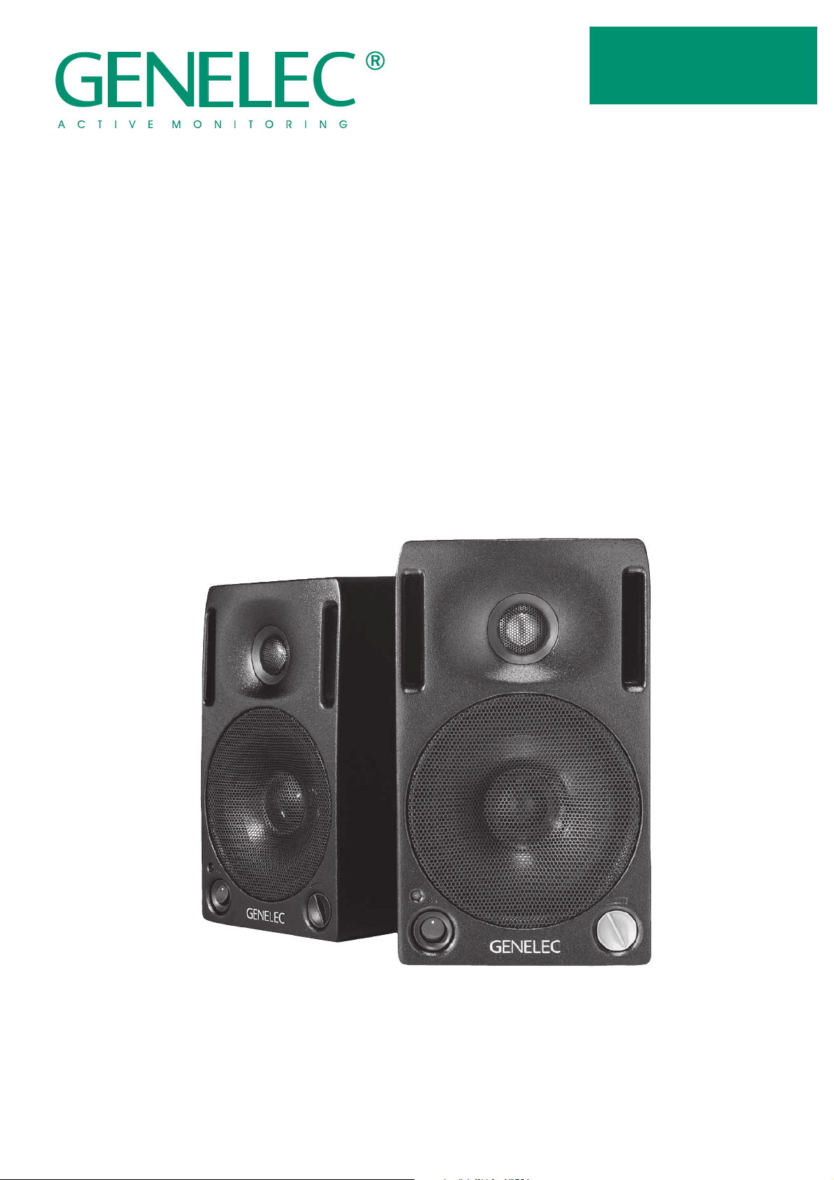
2029B Digital Monitoring System
MAIN FEATURES:
AES/EBU digital audio and analog
audio inputs in a single speaker
system
96 kHz / 24-bit digital audio interface
Automatic detection of word length
and sampling rate
Perfect level match throughout the
system from D/A converter to power
amplifier outputs
Control of stereo pair sensitivity with a
single knob
Control of stereo pair balance with a
single knob
Support for 1091A subwoofer
High system integration
GENERAL DESCRIPTION
Genelec 2029B Digital Monitor-
ing System has a 96 kHz/24 bit
digital audio interface. This has
several significant advantages.
When you are working with a digital audio workstation or you are
processing audio in a modern studio, your signal is digital. The
2029B allows you to monitor what
you have in your digital format.
The 2029B supports all the same
modes of operation as the analog
Genelec 1029A. You can use it
with a subwoofer. You can use it
in surround audio systems.
Due to its compact size, integrated construction, excellent
dispersion and precise stereo imaging, the 2029B system is ideal
for near field monitoring, mobile
vans, digital audio workstations,
broadcast and TV control rooms,
surround sound systems, home
studios, multimedia applications
and also for use with computer
soundcards. The Directivity Control Waveguide (DCW™)
technology provides excellent
frequency balance even in difficult acoustic environments.
leads to smaller noise and distortion level. The typical word length
in CD records is 16 bits. Studio
recording systems use word
lengths of 20 bits and above.
The sampling rate determines
what frequencies can be represented in the digital audio signal.
A higher sampling rate allows higher frequencies to be recorded.
Converting the digital presentation to an analog signal using a D/
A converter involves potential
sources of error. Your digital-toanalog converter may have
inferior performance, or it may be
misaligned with your amplifiers.
The interface between the converter and the amplifier may distort
the signal or change the frequency balance. The monitoring
volume level may need to be
adjusted in the digital domain instead of analog. Genelec 2029B
allows you to solve all of these
problems. The alignment of the
whole system from the digital input connector is carefully
balanced, to make sure that you
hear the whole digital truth, and
nothing but the truth. All you have
to do is to supply the digital signal, and adjust for the volume you
desire.
INTEGRATED
CONSTRUCTION
As the digital interface and amplifiers are built into the speaker
enclosure, the only connections
required are the mains supply
and the digital (or analog) input
signal, making the 2029B very
easy to set up and use.
DIGITAL AUDIO
The quality of a digital audio sig-
nal is defined by two parameters:
word length and sampling rate.
The word length defines how precisely the audio signal is
represented. Longer word length
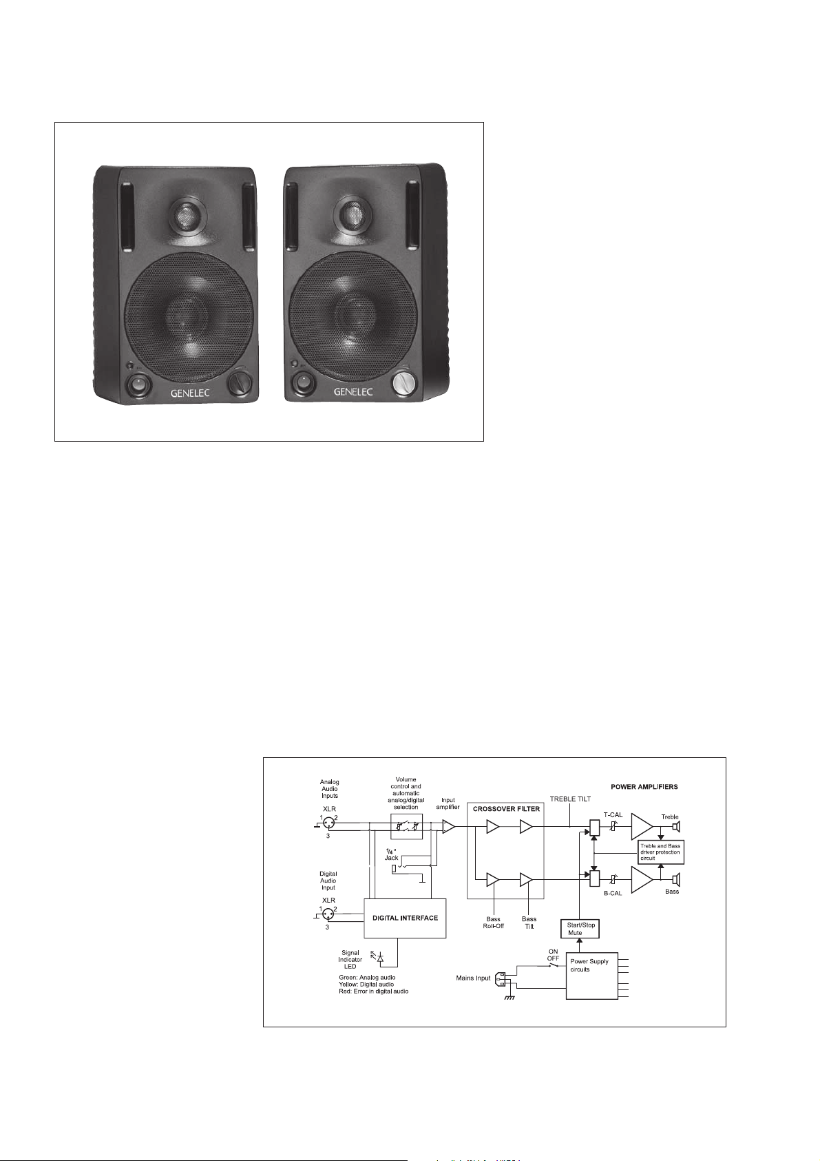
Figure 1: 2029B Digital block diagram showing D/A converter, active crossover filters, power
amplifiers and driver units
Page 3

DIGITAL INTERFACE
ITIS FORBIDDEN TO UNDO ANY SCREWS ON THIS EQUIPMENT. SERVICING ANDITIS FORBIDDEN TO UNDO ANY SCREWS ON THIS EQUIPMENT. SERVICING AND
ADJUSTMENTMUST ONLY BE CARRIED OUT BY QUALIFIED SERVICE PERSONNEL.ADJUSTMENT
MUSTONLY BE CARRIED OUT BY QUALIFIED SERVICE PERSONNEL.
NEVEROPERATE THIS EQUIPMENT WITHOUT A PROPER EARTHED MAINS CONNECTION.NEVER
OPERATETHIS EQUIPMENT WITHOUT A PROPER EARTHED MAINS CONNECTION.
THISEQUIPMENT IS CAPABLE OF PRODUCING SOUND PRESSURE LEVELS IN EXCESS OFTHIS
EQUIPMENTIS CAPABLE OF PRODUCING SOUND PRESSURE LEVELS IN EXCESS OF
85dBWHICH MAY CAUSE PERMANENT HEARING DAMAGE.85dB
WHICHMAY CAUSE PERMANENT HEARING DAMAGE.
ENSURETHAT THE CORRECT VOLTAGE IS SELECTED BEFORE CONNECTING TO THE MAINS.ENSURE
THATTHE CORRECT VOLTAGE IS SELECTED BEFORE CONNECTING TO THE MAINS.
WARNING
ELECTRIC SHOCK HAZARD!ELECTRIC SHOCK HAZARD!
GREEN- ANALOG MODEGREEN- ANALOG MODE
YELLOW- DIGITAL MODEYELLOW
-DIGITAL MODE
RED- DIGITAL AUDIO ERRORRED
-DIGITAL AUDIO ERROR
DIGITALINPUT 3 (XLR)DIGITAL INPUT 3 (XLR)
AES/EBU DIGITALAES/EBU
DIGITAL
AUDIO INPUT ONLYAUDIO
INPUT ONLY
GND
SYSTEM MODE LEDSYSTEMMODE LED
231
BALANCEDBALANCED
DIGITAL
AUDIO
f
MADE IN FINLANDMADE IN FINLAND
2
3
1
ON
OFF
RIGHT
SPEAKER
THEOVERALL SYSTEM LEVEL IS CONTROLLED BY THETHEOVERALL SYSTEM LEVEL IS CONTROLLED BY THE
ROTARYKNOB ON THE FRONT OF THIS SPEAKER.ROTARY
KNOBON THE FRONT OF THIS SPEAKER.
THISDIGITAL SPEAKER MUST ONLY BE USED ON THETHIS
DIGITALSPEAKER MUST ONLY BE USED ON THE
RIGHTHAND SIDE OF A STEREO SYSTEM.RIGHT
HANDSIDE OF A STEREO SYSTEM.
ANALOGINPUT 1 &ANALOG
INPUT1 &
DIGITALLINK (XLR)DIGITAL
LINK (XLR)
THEROTARY KNOB ON THE FRONT OF THE LEFT HANDTHE
ROTARYKNOB ON THE FRONT OF THE LEFT HAND
SPEAKERSHOULD BE TURNED FULLY CLOCKWISE TOSPEAKER
SHOULDBE TURNED FULLY CLOCKWISE TO
ENSURETHAT THE SYSTEM IS CORRECTLY BALANCED.ENSURE
THATTHE SYSTEM IS CORRECTLY BALANCED.
115/ 230 V115 / 230 V
~
50/60Hz50/ 60 Hz
90Watts90
Watts
BI-AMPLIFIEDACTIVE MONITORBI-AMPLIFIEDACTIVE MONITOR
INPUT2 & SUBWOOFERINPUT2 & SUBWOOFER
OUTPUT (1/4" JACK)OUTPUT
(1/4"JACK)
2029BR
DIGITAL
GENELECR
1/4"JACK1/4"JACK
2
XLR
3
1
TONECONTROLSTONECONTROLS VOLTAGESELECTORVOLTAGESELECTOR
GND
+
-
PIN SIGNALPIN SIGNAL
1
2
3
ANALOG INPUT 1 (XLR)
ANALOG INPUT 2 (1/4" JACK)
MAINS CONNECTOR
MAINS
VOLTAGE
SELECTOR
TONE CONTROL SWITCHES:
1: TREBLE TILT
2: BASS ROLL-OFF
3 & 4: BASS TILT
DIGITAL INPUT 3 (XLR)
FOR AES/EBU SIGNAL
The digital audio input comprises
of a digital audio receiver and a
digital-to-analog converter (D/A
converter). The digital input accepts an AES/EBU digital audio
signal having a word length up to
24 bits and up to 100 kHz sampling rate. The D/A converter has
high resilience to clock jitter and
has excellent linearity.
DRIVERS
The bass frequencies are repro-
duced by a 130 mm (5") bass
driver mounted in a 4.5 litre vented cabinet. The -3 dB point lies
at 68 Hz and the frequency response extends down to 65 Hz
(-6 dB).
The high frequency driver is a 19
mm (3/4") metal dome. Uniform
dispersion control is achieved with
the revolutionary DCW™ Technology pioneered by Genelec.
Magnetic shielding is standard
on Genelec 2029B. Shielding is
vital for applications such as video post production, where stray
magnetic fields must be minimized.
CROSSOVER
AMPLIFIERS
The amplifier unit is built inside the
speaker enclosure. The bass and
treble amplifiers both produce
40 W of output power. The fast,
low distortion amplifiers are capable of driving a stereo pair to
peak output sound pressure levels in excess of 110 dB at 1 m. The
unit incorporates special circuitry for driver overload protection.
DIGITAL AND ANALOG
SIGNAL MANAGEMENT
The digital interface is housed in
the speaker marked as "RIGHT
SPEAKER". The balanced AES/
EBU digital signal is fed into this
unit via a XLR connector. In digital
mode the speakers are connected to each other with a balanced
cable, which carries the converted analog signal to the "Left"
speaker. In digital mode the output level for both speakers is
controlled with the potentiometer
on the "Right" unit. The balance is
adjusted with the potentiometer
on the "Left" unit.
In analog mode both speakers
are connected individually to the
signal source with balanced audio cables. In this mode the output
level is adjusted separately on
each 2029B unit.
panel. The tone control has four
switches and can adjust 'treble
tilt', 'bass tilt' and 'bass roll-off.'
The factory settings for these are
'ALL OFF' to give a flat anechoic
response. Figure 5 overleaf
shows the effect of the controls
on the anechoic response.
MOUNTING OPTIONS
There are several possibilities for
mounting the 2029B Digital. On
the base of the monitor is a
3
UNC threaded hole which can accommodate a standard
microphone stand. There is a
provision for an Omnimount®
size 50 bracket,for which two
M6x10mm screws are required.
Alternatively the speaker can be
hung on M4 screws with suitable
heads by one of the three keyhole slots on the backpanel. The
speaker can be hung in a horizontal or vertical position. Friction
pads are provided for placement
on a shelf or a stand.
OPTIONS
/8"
Order code Description
1029-404 Wall Mount
1029-405 Ceiling Mount
1029-420 Soft carrying bag
The active crossover network is
acoustically complementary and
the slopes are 24 - 32 dB/octave.
The crossover frequency is 3.3
kHz. The room response controls ('treble tilt', 'bass tilt' and
'bass roll-off') allow exact match
to any installation.
TONE CONTROLS
The response of the system usu-
ally has to be adjusted to match
the acoustic environment. The
adjustment is done by setting the
tone control switches on the rear
Figure 3: Connecting a pair of 2029B Digitals to a digital input signal
Figure 2: 2029B Digital outer dimensions,
with the reference axis between the bass
and the treble drivers.
Figure 4: 2029B Digital "Right" speaker backpanel
Page 4

2029B
Figure 5: The curve above shows the effect of the 'treble tilt',
'bass tilt' and 'bass roll-off' controls on the free field response.
SYSTEMSYSTEM
SYSTEM
SYSTEMSYSTEM
SPECIFICATIONSSPECIFICATIONS
SPECIFICATIONS
SPECIFICATIONSSPECIFICATIONS
Lower cut-off frequency, -3 dB: < 68 Hz
Upper cut-off frequency, -3 dB:
Free field frequency response of system: 70 Hz - 18 kHz
Maximum short term sine wave acoustic output on axis
in half space, averaged from 100 Hz to 3 kHz:
> 100 dB SPL
Maximum long term RMS acoustic output in same
conditions with IEC weighted noise (limited by driver unit
protection circuit): @ 1m
Maximum peak acoustic output per pair on top of
console,
@ 1 m from the engineer with music material:
Self generated noise level in free field @ 1m on axis:
Harmonic distortion at 85 dB SPL @ 1m on axis:
Drivers: Bass 130 mm (5") cone
Weight: 5.7 kg (12.5 lb)
Dimensions:
Freq: 75...150 Hz < 3%
Treble 19 mm (
Height 247 mm (9 3/4")
Width 151 mm ( 5
Depth 191 mm (7
@ 0.5m
@ 0.5m
> 110 dB
< 10 dB (A-weighted)
> 150 Hz < 1%
Both drivers are magnetically
shielded
> 20 kHz
(± 2.5 dB)
@ 1m
> 106 dB SPL
> 98 dB SPL
> 104 dB SPL
3
/4") metal dome
15
/16")
1
/2")
CROSSOVERCROSSOVER
CROSSOVER
CROSSOVERCROSSOVER
SECTIONSECTION
SECTION
SECTIONSECTION
Analog inputs:
Input 1: XLR female, balanced 10kOhm
1
/4 " Jack socket, balanced 10kOhm
Input 2:
Volume control:
Subsonic filter below 68 Hz :
1091A Subwoofer output (input 2) at 100db SPL:
Ultrasonic filter above 25 kHz: 12 dB/octave
Crossover frequency, Bass/Treble: 3.3 kHz
Crossover acoustical slopes: 24 - 32 dB/
Treble tilt control operating range: 0 to -2 dB
Bass roll-off control operating in a -6 dB step @ 85 Hz (to
be used in conjunction with the 1091A subwoofer)
Bass tilt control operating range in -2 dB steps:
The 'CAL' position is with all tone controls set to 'off' and
the input sensitivity control to maximum (fully clockwise).
Figure 6: The curve group shows the horizontal directivity
characteristics of 2029B Digital in its vertical configuration
measured at 1m. The lower curve shows the systems power
response.
DIGITALDIGITAL
DIGITAL
DIGITALDIGITAL
SECTIONSECTION
SECTION
SECTIONSECTION
Digital input 3: XLR female
Maximum input word length: 24 bits
Input format: AES/EBU, SP-DIF*
Input termination impedance: 110 Ohms
Variable from Mute to -6 dBu for
100 dB SPL output @ 1m
18 dB/octave
-23 dBu into 33kOhm load
octave
@ 15 kHz
0 to -6 dB @ 150 Hz
Input sampling rate: 29-100 kHz (no de-emphasis)
Jitter resiliance: 0.15 unit intervals
Dynamic range: 113dB (A weighted, triangular PDF
De-emphasis: 50/15us, automatic
Recovered clock jitter: 200 picoseconds RMS typical
* An optional impedance matching adapter (ie. Neutrik BXM)
is requred for SP-DIF formatted signal input.
AMPLIFIERAMPLIFIER
AMPLIFIER
AMPLIFIERAMPLIFIER
SECTIONSECTION
SECTION
SECTIONSECTION
Bass amplifier output power with an 8 Ohm load:
Treble amplifier output power with an 8 Ohm load:
Long term output power is limited by driver unit
protection circuitry.
Amplifier system distortion at
nominal output: THD
Signal to Noise ratio, referred to full output:
Mains voltage: 100/200 or 115/230 V
44.1 kHz (using de-emphasis)
SMPTE-IM
CCIF-IM
DIM 100
Bass
Treble
dither, 24 bit data)
40 W
40 W
< 0.08%
< 0.08%
< 0.08%
< 0.08%
> 90 dB
> 90 dB
All data subject to change without prior notice
Genelec Oy, Olvitie 5
FIN - 74100 IISALMI, FINLAND
Phone: +358 - 17 - 83 881
Fax: +358 - 17 - 812 267
E-mail: genelec@genelec.com
Web: http://www.genelec.com
Voltage operating range: ±10%
Power consumption: Idle 9 VA
Genelec Document BBA2029B001 COPYRIGHT GENELEC OY 1.2000
Full output 80 VA
Genelec Inc, 7 Tech Circle
Natick, MA 01760, USA
Phone: +1 - 508 - 652 - 0900
Fax: +1 - 508 - 652 - 0909
E-mail: genelec.usa@genelec.com
 Loading...