

Gx
770
intra-oral
installation/maintenance
manual
x-ray
system
|
THIS
GENDEX
MANUAL
AT
INSTALLATION
MUST
BE
RETAINED
SITE.
|
X-ray
equipment
The
instructions
read
and
followed
dex
dealers
GX-770
The
unnecessary
can
tors
sary
in
operation.
GX-770
provide
from
exposing
radiation.
may
cause
contained
when
operating
will
be
glad
to
provides a high
X-radiation.
complete
However,
protection,
themselves
IMPORTANT!...
injury
if
used
improperly.
in
this
assist.
you
degree
no
nor
or
others
manual
the
of
protection
practical
GX-770.
in
placing
prevent
to
unneces-
must
design
opera-
be
Gen-
the
from
X-RAY
PROTECTION
Itis
Important
ble
government
provisions
recommendations
Protection
dental
Number
30175,
Personal
are
available.
against
that
you
radiation
of
these
and
Measurements.
X-ray
protection
35
available
Washington,
radiation
You
unnecessary
be
fully
acquainted
protection
regulations
the
National
are
published
from
NCRP
D.C.
20014.
monitoring
are
urged
X-radiation
with
regulations.
are
based
Council
Recommendations
Publication,
and
to
use
exposure.
on
in
NCRP
protective
them
applica-
Many
on
the
Radiation
for
Report
P.O.
Box
devices
to
protect
GENDEX
This
direction
assembly,
This
direction
through
Basic
service
CORPORATION
provides
check-out,
also
6)
data
information
adjustment
provides
is
also
and
procedures
provided
to
assemblers
certification
to
to
include
FOREWARD
for
installation
procedures.
be
followed
basic
theory,
of
the
GX-770.
(Sections 2 through
for
periodic
scheduled
troubleshooting
and
The
installation
6)
maintenance.
parts.
(Sections 9 and
GX
data
includes
(Sections
10)
770
3
Section
1
2
Step-by-step
3
4
Preinstallation
This
information
installers
the
installation
preinstallation
remote
special
Installation
station,
mounting
Data
is
as
reference
site
preparation.
4X4
.......................
instructions
assembly,
paration
support)
4X4
procedures.
Electrical
This
checking
electrical
tion
check-out
tion
intervals
System
providing
requirements
are
mount
Calibration
section
and
calibrations.
is
performed
procedure
and
also
as
and
completed.
and
special
provides
adjusting
at
periodic
requested
Function
...............
provided
for
mount
procedures.
for
data
to
completion
Includes
and
for
that
site
pre-
(power
Includes
mounting
..............
instructions
the
GX-770
This
calibra-
as
part
of
the
during
by
(1
the
installa-
year)
owner.
Checks
TABLE
check
of
and
for
......
OF
Page
1-1
CONTENTS
Section
6
Final
This
final
Mechanical
This
check
and
ease
suspension
Remote
This
assembly
the
Electrical
This
operation
troubleshooting
10
This
number
components
Assembly
section
provides
assembly
Adjustments...........
section
and
provides
adjust
tubehead
in
positioning
and
Station
section
provides
and
GX-770
Remote
Troubleshooting
section
section
provides
of
the
identifies
of
major
and
...................
instructions
and
trimout
of
the
unit.
procedures
the
suspension
to
obtain
the
maximum
GX-770
tubehead.
Installation.........
instructions
wiring
connections
Station.
.........
information
GX-770
and
basic
information.
the
ordering
GX-770
other
exchange
service
parts.
Page
6-1
for
7-1
to
8-1
for
of
9-1
on.
To
check-out
tem
compliance
standards.
for
tenance.
5
Certification
This
the
Product
Government
form.
following
This
periodic
section
assembler
Locator
and
test a GX-770
assembly,
with
performance
section
(1
year)
......................
provides
to
fill
cards
FD-2579
to
insure
also
is
used
scheduled
instructions
out
the
and
“Certification”
main-
GENDEX
the
US
sys-
5-1
for
GENDEX
CORPORATION
GX
770
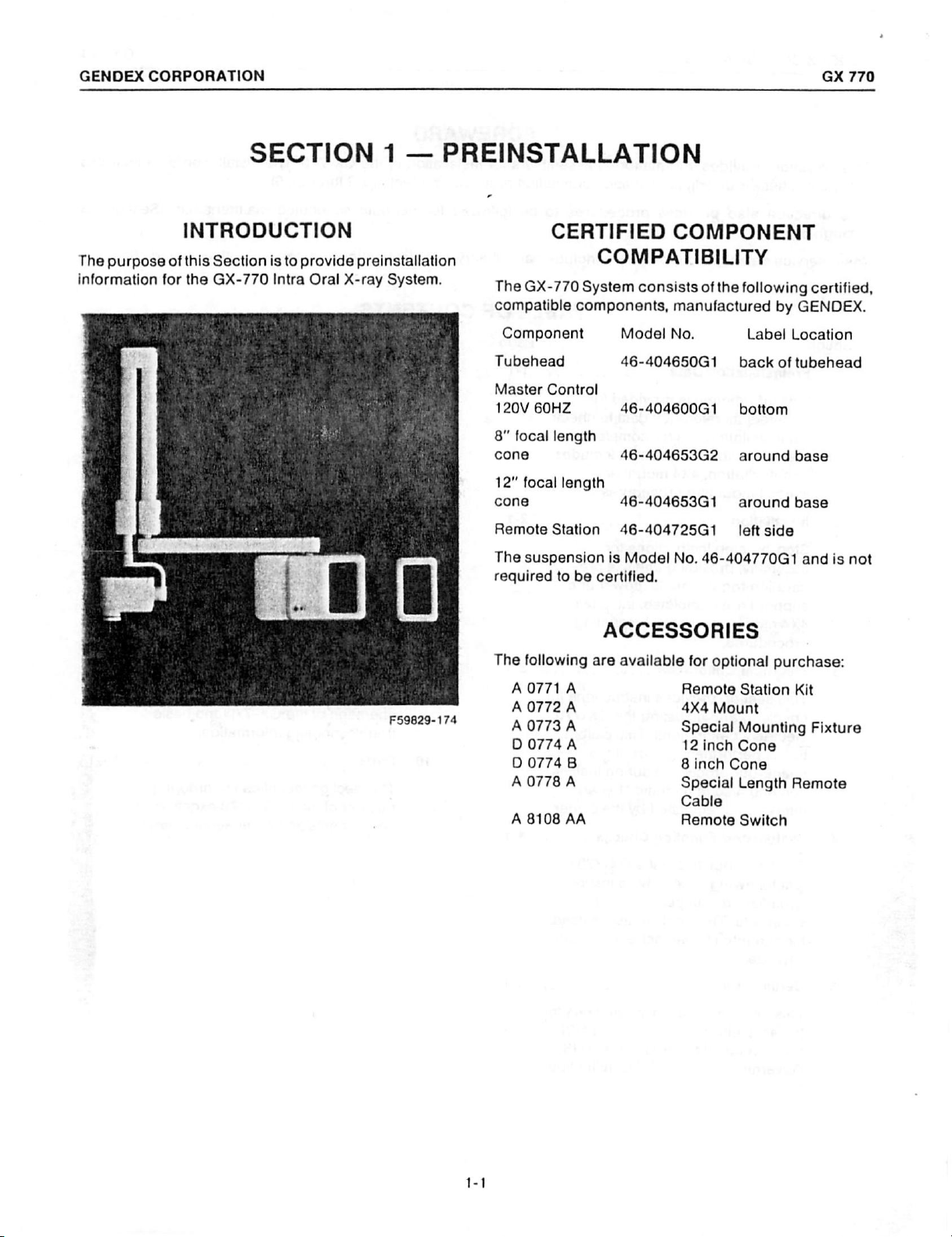
The
purpose
information
SECTION
INTRODUCTION
of
this
for
the
Section
GX-770
is
to
provide
Intra
Oral
1
—
preinstallation
X-ray
System.
PREINSTALLATION
CERTIFIED
COMPATIBILITY
The
GX-770
compatible
Component
Tubehead
Master
120V
60HZ
8"
focal
cone
12” focal
cone
Remote
The
suspension
required
System
components,
Control
length
length
Station
to
be
consists
Model
46-404650G1
46-404600G1
46-404653G2
46-404653G1
46-404725G1
is
Model
certified.
COMPONENT
ofthe
following
manufactured
No.
No.
Label
back
bottom
around
around
left
side
46-404770G1
by
GENDEX.
Location
of
tubehead
base
base
and
certified,
is
not
F59829-174
The
A0771A
A
A
D
О
А
A
ACCESSORIES
following
0772
0773
0774
0774
0778
8108
are
A
A
A 12
В
А
AA
available
for
optional
Remote
4X4
Mount
Special
inch
8
inch
Cone
Special
Cable
Remote
purchase:
Station
Kit
Mounting
Cone
Length
Remote
Switch
Fixture
GENDEX
CORPORATION
GX
770
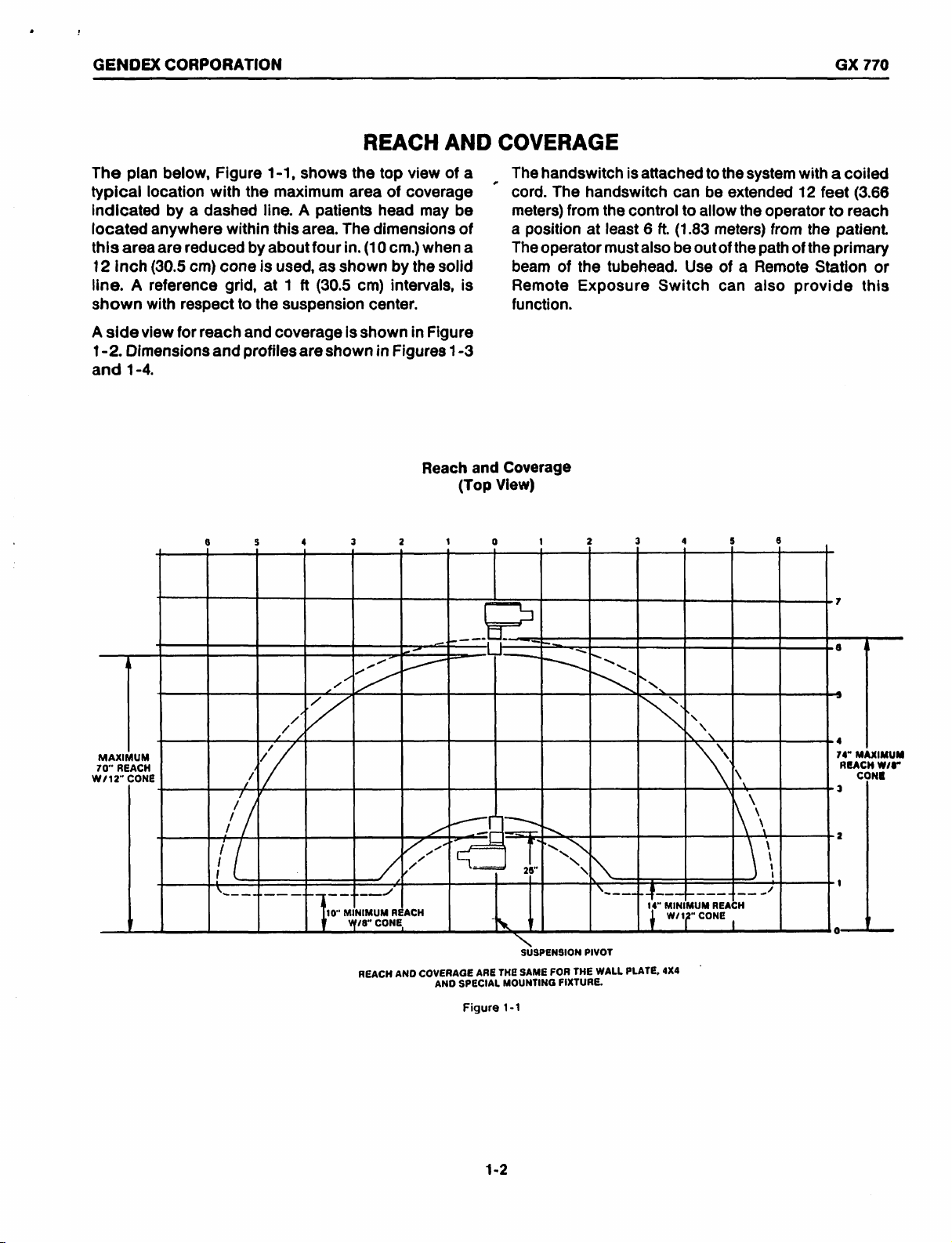
The
plan
below,
typical
indicated
located
this
12
line. A reference
shown
A
1-2.
and
location
anywhere
area
inch
(30.5
with
side
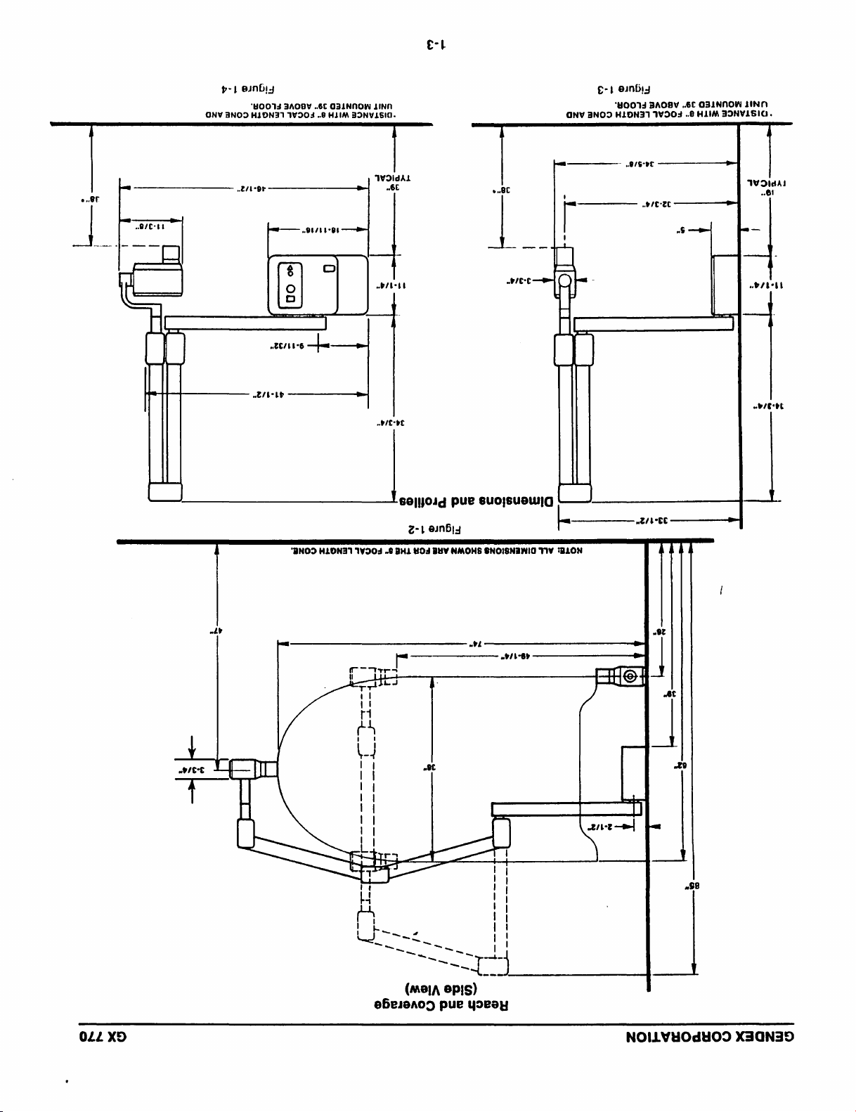
view
Dimensions
1-4.
with
by a dashed
are
reduced
cm)
respect
for
reach
and
8
Figure
the
within
by
cone
grid,
to
the
and
profiles
5
REACH
1-1,
shows
maximum
line. A patients
this
area.
about
is
used,
at 1 ft
suspension
coverage
are
4
The
four
as
shown
(30.5
shown
the
area
in.
(10
cm)
is
shown
3 2
top
view
of
coverage
head
may
dimensions
cm.)
when
by
the
solid
intervals,
center.
in
Figure
in
Figures
Reach
AND
of
a
be
of
a
is
1-3
and
(Top
1
COVERAGE
The
handswitch
cord.
The
meters)
a
The
beam
Remote
function.
Coverage
View)
from
position
operator
of
1
the
Exposure
is
attached
handswitch
the
control
at
least 6 ft.
mustalso
tubehead.
Switch
2
3 4 5
can
to
allow
(1.83
be
outof
Use
to
be
the
system
extended
the
operator
meters)
of a Remote
can
the
from
path
also
6
with a coiled
12
feet
(3.66
to
reach
the
patient.
of
the
primary
Station
provide
this
or
MAXIMUM
W/12"
1
CONE
VÆ
и
/
/
/
7
7
/
/
/
/
/
1
|
i
XL]
ルー
2
7
4
+
Ш
10"
MINIMUM
W/8"
CONE
REACH
esa
[一 一 一
>
lati
レー
|
ンプ
Papa
ンズ
レ
и
REACH
COVERAGE
AND
AND
”|
-|
一
ARE
SPECIAL
Figure
|
|
」
THE
MOUNTING
1-1
ο
ος.
mn
—
26"
SUSPENSION
SAME
= に
「
TA
SN
N
THE
FOR
FIXTURE.
m
S
NS
N
N
\
NON
N
\
N
N
q
\
N
N
ュー
PIVOT
WALL
r
ニー 上 ーー
|
| — 4
14"
MINIMUM
|
ΜΜ
REACH
o
CONE
|
4X4
PLATE,
|
в
|
a
-
4
74"
MAXIMUM
REACH
W/8°
CONE
3
\
\
1
【
à
2
1
;
p-1
esnbiy
‘40074
3A08Y
..6£
ONV
3NOD
HJONA1
14303
..6
CIINNON
HJIM
¿INN
JINVI6I0.
£-1
01nbi3
‘40015
BAOBY
„6C
NY
3ANOD
HLON37
1W303
„6
OJINNOW
HLIM
JINN
JINVISIG.
0.81
pe
WOIdAL
.6E
©
]
HLON ヨ 1
que
、
„bh
À
ge
vit
1YO0』
。0
1
tt
selloid
2-1
@JnB5』
HI
HO
BUY
pue
NMOHS
¿LN
k
|
|
ож
$)
o
o
——
a-
|
ζει 6 Le
I
NOO
„915-18
=
ec
„HCP
euoijsueuulgd
SNOISNINIO
TV
'
トー
ОН
一
-
ис
——————ş
WWDidAi
/CC
一
5
—|
|
pe
—
.
|
KT
W/E
«¿NE
ÁS]
44
022
XD
ος
~
dl
y
に
-一
一
一
+
”个
一
个
一
-全
一
一
一
一
一
一
一
一
一
一
一
一
ビー
-
—
}
——
-<
—
e6e10005
一
—
(쓰이,
—
pue
0016)
yoreay
„dě
AT
fan
|
BY
一
十
一
一
一
一
一
一
一
一
一
1
一
2/12]
S
NOILVHOdHOO
X ヨ QN ヨ り
GENDEX
CORPORATION
GX
770
The
basic
structual
mounting
Special
differ
screws
requirements
screws
while
hardware
Fixture
might
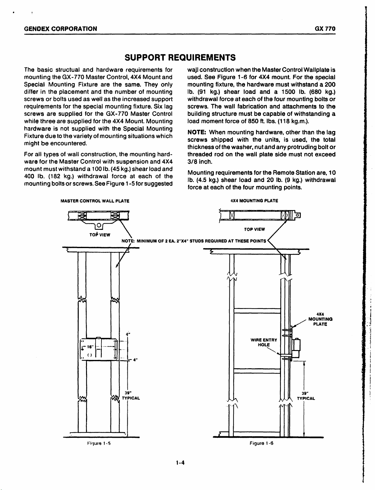
For
ware
mount
400
mounting
Mounting
in
the
or
are
three
due
be
encountered.
all
types
for
the
must
Ib.
(182
the
bolts
supplied
are
is
to
withstand a 100
bolts
and
GX-770
Fixture
placement
used
as
for
the
special
for
supplied
not
supplied
the
variety
of
wall
construction,
Master
MASTER
kg.)
or
screws.
Control
withdrawal
CONTROL
hardware
Master
are
and
well
the
for
the
with
of
mounting
See
WALL
TOP
VIEW
Control,
the
the
number
as
the
increased
mounting
GX-770
4X4
the
the
with
suspension
Ib.
(45
kg.)
force
Figure
PLATE
NOTE:
SUPPORT
requirements
4X4
Mount
same.
Mount.
Special
They
of
mounting
fixture.
Master
Mounting
Mounting
situations
mounting
shear
load
at
each
1-5
for
suggested
MINIMUM
support
Control
and
REQUIREMENTS
and
only
Six
which
hard-
4X4
and
of
OF 2 EA.
for
lag
the
wall
used.
mounting
Ib.
withdrawal
screws.
building
load
NOTE:
screws
thickness
threaded
3/8
Mounting
Ib.
force
2"X4"
STUDS
construction
See
Figure
fixture,
(91
kg.)
shear
force
The
wail
structure
moment
inch.
(4.5
at
REQUIRED
force
When
kg.)
mounting
shipped
of
the
rod
on
requirements
shear
each
of
<
И
)
AT
e
when
the
1-6
for
the
hardware
load
at
each
fabrication
must
of
850
with
washer,
the
wall
load
the
four
4X4
MOUNTING
TOP
THESE
POINTS
Master
4X4
mount.
must
and a 1500
of
the
four
and
be
capable
ft.
Ibs.
hardware,
the
units,
nutand
plate
side
for
the
Remote
and
20
mounting
PLATE
VIEW
Control
For
withstand a 200
Ib.
mounting
attachments
of
withstanding
(118
kg.m.).
other
is
used,
any
protruding
must
Station
Ib.
(9
kg.)
points.
5
Wallplate
the
special
(680
kg.)
bolts
to
than
the
the
total
bolt
not
exceed
are,
withdrawal
is
or
the
a
lag
or
10
を
Figura
1-5
TYPICAL
I
Y
WA
HAN
WIRE
HOLE
Figure
A
Rh
~
ENTRY
<
<
L
T
1-6
\
MOUNTING
39”
TYPICAL
|
4X4
PLATE
1-4
GENDEX
CORPORATION
GX
770
Line
Voltage
maximum,
Maximum
Maximum
110TO130V
line
line
'
60HZ
range:
no
load
110
volts
current:
regulation:
10
FOR
FLUSH
PORTING
TO
MOUNTED
|
ELECTRICAL
minimum
amperes
3%
CONCEALED
BOX
CONDUIT
(CONCEALED
during
MOUNTED
STUD,
CENTER,
39”
(1M)
TO
15
AMP
CIRCUIT
BREAKER
WIRING
JUNCTION
LOCATED
IF
JUNCTION
WIRING
to
exposure
BOTTOM
ABOVE
POWER
130
volts
OPTION:
BOX
42
IN.
GF
FLOOR,
BOX
OPTION)
ANCHORED
(1.08)
FROM
WALLPLATE
REQUIREMENTS
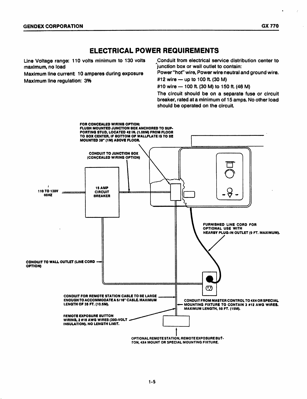
Conduit
junction
Power
#12
#10
The
breaker,
should
TO
FLOOR
19
from
box
“hot”
wire — up
wire — 100
circuit
rated
be
operated
SUP-
TO
BE
electrical
or
wire,
should
at a minimum
service
wall
outlet
to
to
ft.
Power
100
wire
ft.
(30
(30
M)
to
be on a separate
on
the
circuit.
distribution
contain:
neutral
M)
150
ft.
(46
of
15
amps.
and
M)
fuse
center
ground
or
No
other
to
wire.
circuit
load
CONDUIT
OPTION)
TO
WALL
OUTLET
(LINE
CONDUIT
ENGUGH
LENGTH
REMOTE
WIRING,
INSULATION).
CORD
FOR
REMOTE
TO
ACCOMMODATE
OF
35
FT.
EXPOSURE
2
#16
AWG
NO
—=
(10.5).
BUTTON
WIRES
LENGTH
STATION
A
(300-VOLT
LIMIT.
CABLE
5/16"
TO
CABLE.
OPTIONAL
TON,
SE
MAXIMUM
一
4X4
LARGE
REMOTE
MOUNT
STATION,
OR
|
re
一
REMOTE
SPECIAL
MOUNTING
FUANISHED
OPTIONAL
NEARBY
PLUG-IN
Je
CONDUIT
MOUNTING
MAXIMUM
EXPOSURE
FROM
CD
MASTER
FIXTURE
LENGTH,
FIXTURE.
BUT.
LINE
USE
WITH
OUTLET
CONTROL
TO
CONTAIN 3 #12
30
FT.
(15M).
CORD
TO
FOR
(9
4X4
FT.
MAXIMUM).
OR
AWG
SPECIAL
WIRES,
1-5
GENDEX
CORPORATION
GX
770
The
certified
ply
with
Subchapter
X-ray
equipment
tories,
mechanical
87724.
CSA,
Class
(/
|
1.11/32"
:
m
<
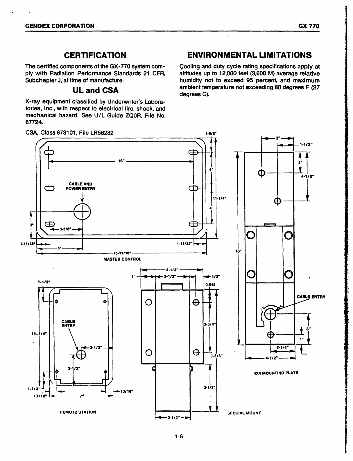
components
Radiation
J,
Inc.,
with
hazard.
873101,
中
<
C
СВ
ыы
5“
CERTIFICATION
of
the
GX-770
Performance
at
time
UL
classified
respect
See U/L
File
CABLE
POWER
of
manufacture.
and
to
LR56282
AND
ENTRY
Standards
CSA
by
Underwriter’s
electrical
Guide
|
D
ыы
18-11716"
MASTER
system
fire,
ZQOR,
。
CONTROL
com-
21
Labora-
shock,
File
CFR,
and
No.
ENVIRONMENTAL
Cooling
altitudes
humidity
ambient
degrees
and
duty
up
to
not
to
temperature
C).
1-5/8"
NH
1-11/32"
9
y
C]
a
|
4
|
+
cycle
12,000
exceed
rating
feet
not
exceeding
1
18"
LIMITATIONS
specifications
(3,600
95
M)
average
percent,
80
に
©
©
apply
relative
and
maximum
degrees F (27
Le
A
3
n
LI.
0
at
1-4/2"
nm
11174“
.
|
/J
o
CABLE
ENTRY
NEMOTE
5
STATION
LN
o
at
13/16"
(4-12
1°
bag
2.1/2
[그
O
O
Bo
一
mm
|
|
©
Side
—
112
0.812
|
”
°
|
3/8"
|
1
0
0
.
CABLE
A
|
©
L
a
— —
4X4
SPECIAL
MOUNT
ーー
4-172
MOUNTING
— вы
ry
|":
し
PLATE
ENTAY
|
|
GENDEX
CORPORATION
GX
770
Prior
to
beginning
lation
requirements
cludes
quate
power
confirming
for
mounting
requirements
Preinstallation
Remote
this
NOTE:
Section 8 or
kit.
calibration
Station.
If
mounting
control,
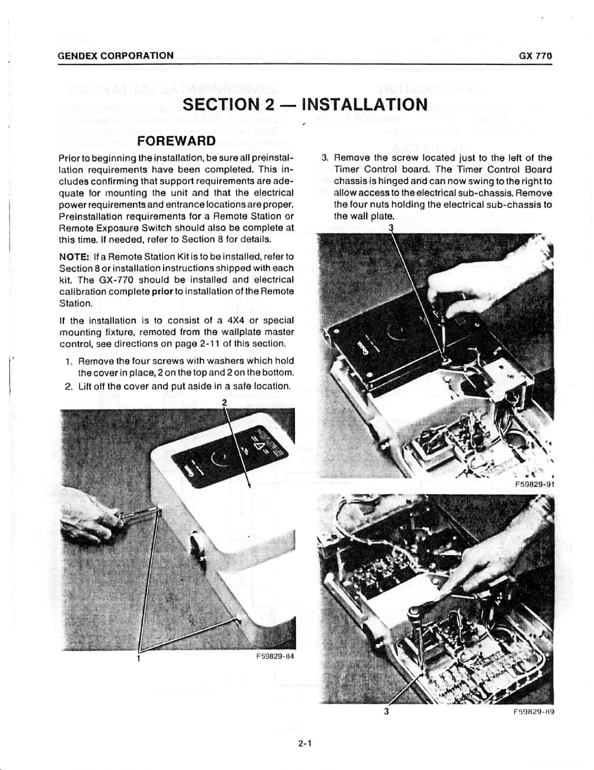
1.
2.
Exposure
time.
Ifa
The
the
installation
see
Remove
the
cover
Lift
off
If
needed,
Remote
installation
GX-770
complete
fixture,
directions
the
in
the
FOREWARD
the
installation,
have
that
support
the
unit
and
entrance
requirements
Switch
Station
should
is
remoted
four
place, 2 on
cover
should
refer
to
instructions
be
prior
to
to
consist
on
page
screws
and
put
SECTION
be
sure
been
completed.
requirements
and
that
locations
for a Remote
also
be
Section 8 for
Kitis
to
be
installed,
shipped
installed
installation
from
2-11
with
the
top
aside
and
of a 4X4
the
wallplate
of
washers
and 2 on
in a safe
all
preinstal-
This
are
the
electrical
are
Station
complete
details.
with
electrical
of
the
or
this
section.
which
the
location.
2
—
in-
ade-
proper.
or
at
refer
to
each
Remote
special
master
hold
bottom.
INSTALLATION
3.
Remove
Timer
chassis
allow
the
the
Control
access
four
wall
the
screw
is
hinged
to
nuts
holding
plate.
board.
the
located
The
and
can
now
electrical
the
electrical
just
to
the
Timer
Control
swing
to
sub-chassis.
sub-chassis
left
the
Remove
of
the
Board
right
to
to
F59829-84
2-1
3
oe”
4
F59829-91
F59829-89

GENDEX
4.
Lift
protect
in a safe
CORPORATION
off
the
electrical
the
handswitch
location.
sub-chassis,
and
power
being
cord.
sure
Set
to
aside
6.
Using a 1/16”
locate
adequate
present.
Exposure
junction
at
this
located
at
the
proper
7.
Drill
the
1/4"
drill
(1.04
m.)
the
wallplate
floor.
However
altered,
the
centers
mounting
If
Switch
box,
time.
in
the
hole
bit.
above
then
drill
bit,
of
space
the
power
wiring
conduit
Also
lower
height.
This hole
is
this
for
the
to
if
the
and
verify
left
the
finished
be
mounting
height
make
the
and
is
wiring
that
corner
lower
will
39"
(1
must
several
studs.
on
16
Remote
to
be
should
the
junction
off
the
left
lag
normaliy
floor,
m)
above
heightin
be
modified
GX
test
holes
Verify
inch
concealed,
if
that
centers
Station/
be
installed
wallplate
screw
be
40-11
the
bottom
the
finished
step 5 was
accord-
using
box
770
to
an
is
the
is
and
/16”
of
CEE
isi
a
F59829-95
NOTE:
used
supported
See
struction.
mounting.
thickness
threaded
3/8
mounting
supporting a 100
(182
points.
building
load
following
used,
Steps 5 through
to
fasten
by
Section
Lag
When
of
rod
inch.
For
hardware
kg.)
withdrawal
The
structure
moment
procedure
where
5.
Mark
the
plate
at
ceiling
mounting
The
the
to
Preinstallation
height
height
user's
Reach
14
the
Master
wood
studs
1,
Preinstallation
screws
the
washer,
on
any
wall
couple
applicable,
location
39
inches
height
may
choice
and
are
other
hardware
nut
the
wallplate
wall
to
be
Ib.
(45
kg.)
force
fabrication
must
be
of
850
for
mounting
for
for
(1
is
less
than
must
also
be
ofa
high
Coverage
Section
describe
Control
on
16
for
furnished
and
construction,
used
shear
at
each
and
capable
ft.
other
the
bottom
m)
above
87
be
adjusted
orlow
chart
for
additional
the
wallplate
in.
(40.6
suggested
for
is
used,
any
protruding
side
must
must
load
of
the
attachments
of
withstanding
Ibs.
(118
and
leveling
types
edge
the
in.
(221
lowered
to
base
on
be
of
accommodate
procedures
to a wall
cm.)
centers.
wall
con-
this
type
the
total
bolt
not
exceed
the
selected
capable
and a 400
six
mounting
to
the
kg.m.)
hardware.
floor.
cm),
accordingly.
chair.
page
details.
of
may
the
If
then
Refer
1-2
The
wall
the
the
of
or
of
Ib.
a
be
of
8.
Lift
the
left
lag
to
side
wallplate
screw
and
and
tighten
8
into
position
washer.
the
lag
and
Level
screw.
install
the
wallplate
이진
『59829-136
the
lower
side
F59829-140
GENDEX
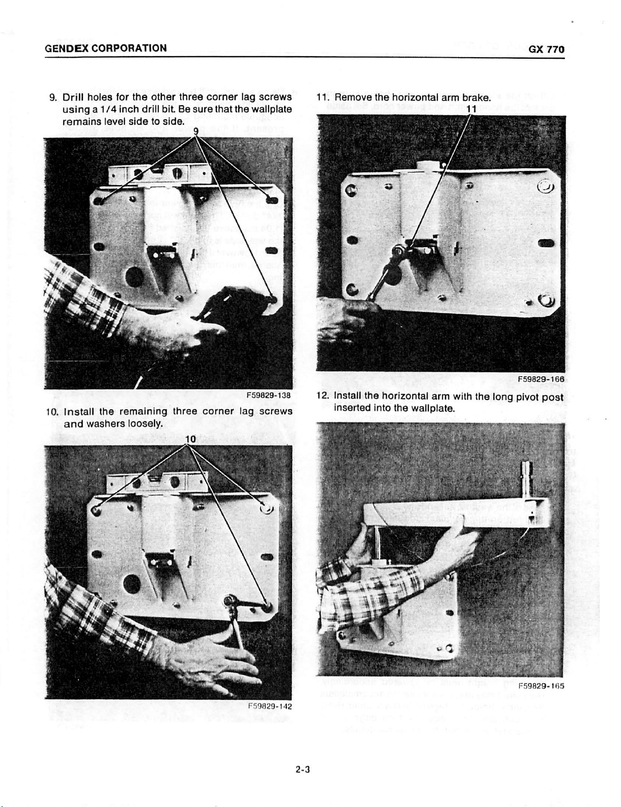
9.
Drill
using a 1/4
remains
CORPORATION
holes
for
the
inch
level
side
other
drill
to
three
bit.
Be
side.
corner
sure
that
lag
the
wallplate
screws
11.
Remove
the
horizontal
arm
brake.
11
GX
770
long
F59829-166
pivot
post
Install
10.
and
the
washers
remaining
loosely.
three
10
corner
F59829-138
screws
lag
12.
Install
inserted
the
horizontal
into
arm
wallplate.
the
with
the
F59829-142
F59829-165
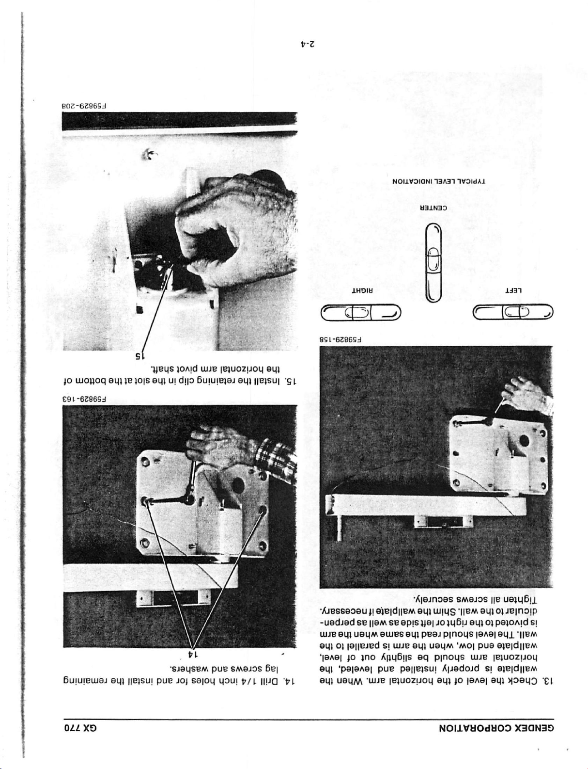
802-6278654
vee
Jo
uohoq
€91-6286S3
5
BUS
euileiols
eui
1OAId
UUJB
ul
dllo
6ululeleledl
IBJUOZIJOU
llelsul
041
“SL
8S1-6286S4
NOILVOIQNI
H31N39
13437
1VOIdAI
Buiuieuu8」
044
ХЭ
eui
IIBJSUI
PUP
*SJ8USEM
』O』
SSIOU
PUR
SM819S
UOUI ヤ /L
Ge|
IIUO
“pl
*
人 ん
eSSeo8u』I
-uedied
Je
ey]
se
[jem
ueym
SBIdIIBA
ey) 이 | 비 16160
Челе!
30
¿no
edl'peleAel
eu}
UBUM
pue
“WE
AleJno9S
9U!
UUIUS
SB
9DIS
Je]
10
eules
ey,
pea.
61
uuJg
eui
usuA
ÁpyBbis
eq
рпоц$
paellelsul 人 AlJedo』d
[E}UOZIIOY
OU}
SA9』oS
"IIBA
8U1 0 JBInoIP
}uB1
8U1
O)
p¡noys
'mo]
|[8A8]
pue
uue
SI
Jo
jane]
NOILVHOdH09
IIB
U81U5I」
PS1OAId
EUL
SI
‘EM
ejejd¡em
jejuozuou
ejejdijem
ey]
HOEY
X30N359
“EL
GENDEX
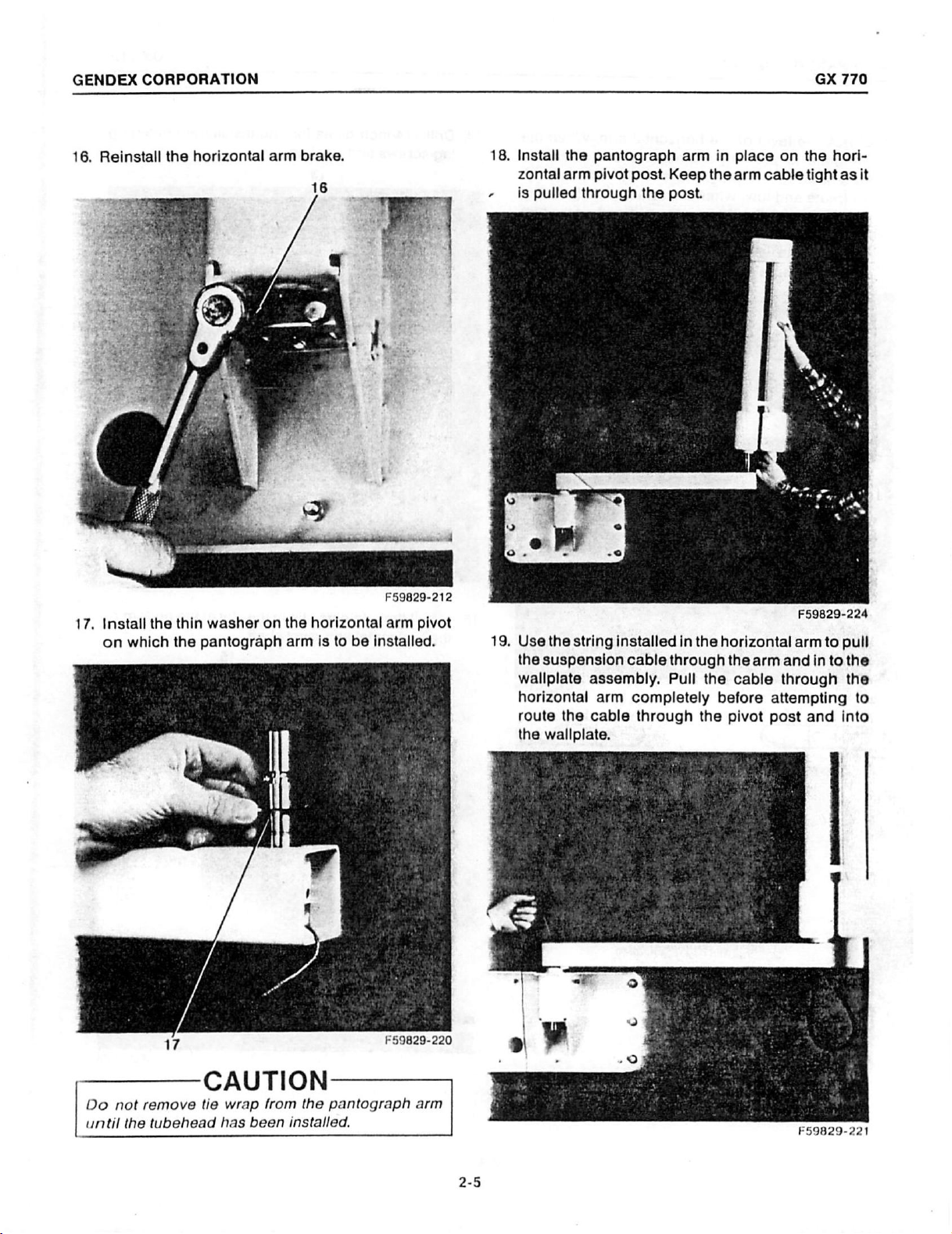
16.
Reinstall
CORPORATION
the
horizontal
arm
brake.
18...
ыы
18.
-
Install
zontal
is
pulled
the
pantograph
arm
pivot
through
post.
the
arm
Keep
post.
in
the
place
arm
on
cable
GX
the
hori-
tight
770
as
it
F59829-212
17.
Install
on
which
the
thin
washer
the
pantográph
on
the
horizontal
arm
is
)
to
be
arm
pivot
installed.
19,
Use
the
wallplate
horizontal
route
the
the
string
installed
suspension
assembly.
arm
the
cable
wallplate.
in
cable
through
Pull
completely
through
the
horizontal
the
the
cable
before
the
pivot
F59829-224
arm
arm
and
through
attempting
post
in
and
to
to
pull
the
the
into
to
Do
until
not
the
remove
tubehead
CAUTION
tie
wrap
from
has
been
installed.
the
pantograph
F59829-220
arm
F59829-221
2-5
GENDEX
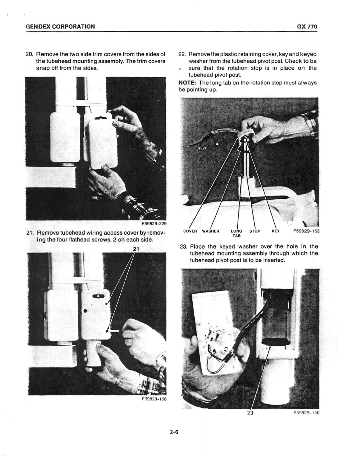
20.
Remove
the
tubehead
snap
CORPORATION
the
two
mounting
off
from
the
side
sides.
trim
covers
assembly.
from
The
4
the
trim
sides
covers
of
22.
Remove
washer
~
sure
tubehead
NOTE:
be
pointing
that
The
the
from
the
pivot
long
up.
plastic
the
tubehead
rotation
post.
tab
on
retaining
pivot
stop
the
rotation
cover,
post.
is
in
stop
key
Check
place
must
and
GX
770
keyed
to
be
on
the
always
21.
Remove
ing
the
tubehead
four
flathead
wiring
access
screws, 2 on
cover
each
21
F59829-229
by
remov-
side.
COVER
23.
WASHER
Place
tubehead
tubehead
the
LONG
TAB
keyed
mounting
pivot
post
STOP
washer
assembly
is
to
over
be
inserted.
KEY
the
through
F59829-153
hole
which
Y
in
the
the
F59829-156
F59829-150
2-6

GENDEX
24.
Install
mounting
CORPORATION
the
tubehead
assembly
pivot
and
post
through
into
the
the
keyed
tubehead
washer.
26.
<
The
prevent
Install
wires
and
washer.
plastic
the
the
plastic
snap
retaining
tubehead
retaining
into
place
cover
over
CAUTION
cover
from
MUST
falling
over
the
be
out
GX
the
tubehead
key
and
installed
during
use.
770
keyed
to
25.
Install
the
tubehead
pivot
shaft
—
p
— A
the
(OX
key
and
AS
@\
24
on
the
until
the
the
Y
NIDA)
||
,
tubehead
key
slots
WV)
on
fits
the
リ
O
A
É
pivot
into
keyed
shaft.
the
washer.
F59829-
Rotate
hole
|
f
in
147
the
27.
NOTE:
rotation.
Check
tubehead
stop
the
to
Stop
26
tubehead
through
stop.
MUST
rotation
approximately
be
in
place
stops
to
prevent
by
470
F59829-193
rotating
degrees
continuous
from
the
F59829-195

GENDEX
28.
Connect
strip
access
and 4 on
connect
sion
CORPORATION
the
four
and
ground
cover.
ground
Wires 3 and 4 connect
the
terminal
to
the
ground
wire
tubehead
screw
strip.
stud
is
already
wires
on
the
tubehead
Both
to
which
connected.
to
the
ground
the
terminal
wiring
to
wires
wires
suspen-
3
30.
Remove
counter
~
movement
arms.
Adjustment
31.
Reinstall
the
the
balance
ofthe
If
adjustments
the
two
side
tiewrap
of
inboard
Section.
tubehead
trim
panels.
from
the
tubehead
and
are
required,
wiring
the
arm
outboard
access
and
and
pantograph
see
Mechanical
GX
check
for
proper
cover
770
the
and
F59829-197
29.
Attach
cone
to
the
tubehead.
F59829-202
F59829-156
F59829-229

GENDEX
32.
Install
covers
CORPORATION
the
two
arm
on
the
horizontal
end
and
arm.
two
pivot
post
access
-
34,
35.
Check
stop
of
Tighten
wrench,
until
it
brake
the
pantograph
approximately
the
lower
located
firms
up.
This
for
the
pantograph
set
on
arm
240
screw,
the
screw
for
rotation
degrees.
requires
lower
adjusts
arm.
rear
from
5/32”
arm
the
horizontal
GX
770
stop
to
allen
casting,
33.
Tighten
wrench,
then
rotation
graph
NOTE:
additional
36.
Refer
the
top
located
back
off
and
stop
assembly.
Mechanical
to
calibration
32
set
screw,
on
the
1/2
turn.
out
lift
information
requires a 5/32"
lower
rear
screw
for
steps
arm
This
prevention
Adjustment
on
F59829-209
allen
casting,
provides
the
Section
33,
a
panto-
for
35
and
36.
Tighten
wrench
NOTE:
so
horizontal
The
that
35
the
horizontal
socket,
or
horizontal
pantograph
the
arm
moves.
arm
desired.
as
arm
brake
section
brake,
is
normally
opens
36
requires
F59829-34
a
7/16"
adjusted
before
the
F59829-214
2-9
F59829-212

GENDEX
CORPORATION
GX
770
NOTE:
counter
would
Electrical
be
37.
If
the
where
not
sub
visible
after
Reinstall
nuts
removed
the
chassis
be
possible.
NOTE:
cord
wiring
and
Switch
the
If
the
should
connected
GND1.
electrical
is
to
be
If a Remote
components.
-—————_
The
unit
must
building
ground.
Master
visible,
chassis
the
Control
the
serial
they
final
assembly.
electrical
earlier.
should
chassis
be
part
calibration
is
removed
to
the
of
the
CAUTION
be
properly
Conduit
is
and
must
and
placed
sub
Before
be
shifted
to
be
“hard
at
this
appropriate
Station
system,
prior
grounded
grounding
to
be
installed
model
chassis
number
be
removed
in a location
using
tightening
to
the
wired”,
time
and
terminals
or
Remote
you
should
to
connecting
via a wire
is
not
over
labels
from
the
that
will
the
four
the
nuts,
left
as
far
the
power
the
conduit
on
TS1
Exposure
complete
these
to
the
sufficient.
a
as
38.
Connect
ate
terminals
the
suspension
on
oR?
ς
κ.
Sat mom
TS1
and
arm
GND2.
cable
to
the
appropri-
F59829-29
The
unit
to
Section
function
is
now
3, 4,
5,
checks,
capable
and 6 for
certification
of
electrical
producing
and
final
F59829-37
X-rays.
calibration,
Proceed
assembly.
system

GENDEX
CORPORATION
GX
770
The
following
begin
modifications
4X4
wallplate
NOTE:
WITHOUT
load
four
on
or
1.
Steps 1 through 4 remain
and
mounting
2.
Step 5 -
3.
Steps 6 through 9 remain
4.
Step
loosely.
securely.
5.
Step
the
6.
Remove
special
7.
Install
the
lation
steps
page
2-1
noted
Special
master
Mounting
90
10 - Install
11 - Remove
wallplate.
appropriate
the
suspension
Ib.
(40.9
points.
Height
Level
the
mounting
the
4X4
Section
Mounting
control.
wiring
of
requirements
may
the
Set
or
mounting
for
INSTALLATION
4X4
OR
the
installation
of
this
section
are
applicable
Fixture,
are:
kg.)
withdrawal
be
modified
the
remaining 3 corner
wall
plate.
the
horizontal
aside
for
access
fixture.
special
hardware.
mounting
procedure
for
remoted
the
same.
for
the
30
Ib.
force
to
the
same.
Tighten
reinstallation.
cover
mounting
requirements.
DIRECTIONS
SPECIAL
which
along
(13.6
suit
arm
from
with
installation
from
Master
Control
kg.)
at
each
preference.
lag
screws
all
lag
screws
brake
the
4X4
fixture
See
Preinstal-
shear
of
using
MOUNTING
the
of
a
the
the
from
or
FOR
8.
Step
pivot
fixture.
SYSTEM
FIXTURE
12 - Install
post
inserted
WITH
the
horizontal
into
the
8
4X4
arm
or
special
with
mounting
F59829-104
the
long
9.
Step
13 - Correct
mounting
in
Step
7
F59829-99
fixture
13,
Page
the
to
achieve
2-4.
position
the
of
the
level
4X4
as
described
or
special
F59829-107
2-11

GENDEX
10.
Omit
11.
Install
the
CORPORATION
Step
14.
the
retaining
horizontal
arm
clip
pivot
in
the
shaft.
slot
at
the
bottom
of
13.
14.
Steps
Connect
necting
special
17
through
the
wires
mounting
37
remain
suspension
and
ground
fixture.
the
cable
screw
same.
to
the
on
GX
intercon-
the
4X4
770
or
12.
Step
16 - Install
4X4
or
NOTE:
wallplate.
Use
special
brake
11
the
horizontal
mounting
removed
arm
fixture.
from
the
brake
master
12
F59829-110
onto
the
control
TS1
MASTER
[의
[$
[의
[$]
[의
[$]
의
©]
15.
一
Do
sion
IN
GX-770
CONTROL
|
]
GND2
Connect
ate
terminals
一
not
reverse
cable.
CUSTOMER
WIRING,
the
interconnecting
on
TS1
一
CAUTIOM
red
and
50
3 #
FT.
X
and
black
SUSPENSION
CABLE
FURNISHED
12
AWG
MAX.
wires
GND2.
wires
一
in
to
the
the
F59829-37
SCREW
ON
OR
MOUNTING
FIXTURE
appropri-
suspen-
GND
4X4
SPECIAL
一
F59829-109
2-12

GENDEX
16.
CORPORATION
Install
pivot hole. bolts on
the
plug
button
in
place
on
the
wallplate
17.
Install
the
three
the
4X4
plug
mount.
buttons
to
cover
the
mounting
GX
770
16
“
18.
Reinstall
wiring
the
access
4X4
cover.
or
special
mounting
fixture
F59829-119

GENDEX
CORPORATION
GX
770
SECTION
ELECTRICAL
THE
KEY
LOCK
MUST
ALLOW
CANNOT
THE
“ON”
X-RAY
BE
REMOVED
POSITION.
EXPOSURE.
r——
Radiation
the
electrical
be
placed
available
100108.
Itis
recommended
ments
titled
ibration
copy
form
will
over
from
be
recorded
“Product
Record
should
FD2579
be
calibration.
location/Identification
be
and
BE
TURNED
WHEN
WARNING
produced
the
tubehead
GENDEX
CAUTION
that
by
is
provided
attached
the
numerous
Therefore a lead
Corporation.
all
of
the
installer. A separate
to
the
other
to
NOTE
THE
port.
the
following
for
this
owners
the
90
DEGREES
THAT
THE
SWITCH
——
times
plug
These
plugs
Part
EL
measure-
Log
and
purpose.
copy
installers
IS
during
must
are
No.
sheet
Cal-
One
of
copy.
CALIBRATION
TO
KEY
IN
©
the
Suggested
AC/RMS,
Impulse
Va
2.
3.
4.
3
Instruments:
DC
Voltmeter
Fluke
8030
or
8060
Beckman
Kessler-Ellis
ESD
Make
Plug
distribution
With
Voltmeter
and
Counter
XR201
ιο LO
sure
in
the
the
Master
TP-13
Tech
KT293
the
Master
line
panel.
to
read
on
the
1
Digital
330
Digital
È
Iné
cord
or
Control
100
Relay
к
È
and
Control
DC
Voltmeter
Voltmeter
behead
turn
turned
to
130
Circuit
TP-1
Milliameter
port.
is
turned
on
the
power
off,
connect
VAC
between
Board.
ТР-13
off.
at
an
TP-1
the
AC
These
insure
regulations.
be
advise
calibration
the
installation
obtained,
the
user
INSTRUMENT
The
following
accuracies
tion
is
fully
compliant
Type
of
AC
or
DC
DC
Impulse
Instrument
Voltmeter,
True
RMS
Milliameter
Voltmeter
Counter
If
the
contact
not
measuring
are
needed
Iron
Digital
procedures
is
fully
required
GENDEX
to
operate
to
with
Vane
Meter
must
be
followed
compliant
measurement
the
with
applicable
values
for
guidance,
equipment.
REQUIREMENTS
instruments
insure
applicable
Range
0-150
RMS
0-10
0-20V
0-999
Impulses
80-120V
RMS
with
the
GX-770
regulations:
VAC | +/-1.5V
mA
DC | +/-0.1mA
DC
60HZ
to
cannot
and
required
installa-
Accuracy
+/-0.02V
+/-0
Impulse
i
5.
Turn
reading.
Calibration
110
on
the
and
Master
Record
Record.
130.
Control
the
“No-Load”
This
and
note
line
voltage
voltage
must
F59829-44
the
voltmeter
be
between
on
the
3-1

GENDEX
6.
Set
sure
Control
tion
NOTE:
The
voltage,
CORPORATION
exposure
using
S2
Board.
record.
voltage
must
not
time
to
99
impulses.
(Calibration
Record
variation,
exceed 3 VAC.
“Load”
“No-Load”
Switch)
voltage
Make
on
minus
an
the
on
calibra-
“Load”
expo-
Timer
Turn
ing.
calculated
correct,
obtain
Load”
Turn
10.
11.
With
Voltmeter,
used
on
on
Meter
reading
off
the
in
the
Timer
the
the
Master
reading
in
step
adjust
R6
correct
on
Master
Master
step 8 and
Control and
using
Control
Control.
should
7,
+/-0.05
on
the
value.
the
Calibration
Control
the
same
9,
between
Board.
Note
be
equal
VDC.
Timer
Record
remove
turned
meter
TP-2
voltmeter
to
the
If
voltage
Control
the
final
Record.
meter
off,
connect a DC
and
meter
(+)
and
GX
read-
voltage
is
Board
“Vcal
leads.
scale
TP-4
770
not
to
(-)
7.
Calculate
following
“Load”
EXAMPLE
8.
With
Voltmeter
and
Voltage
10
the
TP-4
Vcal
formula:
Master
to
read
(-)
on
(load),
-
Vcal
11808
0
Control
10
to
the
Timer
from
“Load”
turned
20
VDC
Control
step
11.8
off,
connect a DC
between
Board.
R6
6,
using
TP-4
F59829-47
the
TP-3
(+)
TP-3
NOTE:
selector
in
these
Removal
knob
is
photos
R11
of
the
front
not
required
to
provide a better
TP-2
(graphic
for
calibration.
view.
panel)
TP-4
F59829-16
and
time
Removed
F59829-19
3-2
12.
13.
Turn
should
the
Timer
Record
Turn
on
off
the
be
2.00
Control
final
Master
Master
+/-0.01
“Vref”
Control
Control.
VDC.
Board
reading
and
Voltmeter
If
not,
to
obtain
on
Calibration
remove
reading
adjust
R11
2.00
VDC.
Record.
meter leads.
on

GENDEX
14.
With
Voltmeter
and
CORPORATION
the
Master
to
read
TP-13
on
TP-13
the
Control
100
to
Relay
TP-11
turned
130
VAC
Circuit
off,
connect
between
Board.
S2
an
AC
TP-11
GX
770
17.
With
the
tubehead
read 5 to
ground
(-).
Master
pivot
10
mA
Control
cover.
between
turned
Connect a DC
the
mA
off,
test
remove
mA
meter
point
(+)
the
to
and
15.
Turn
99
impulses.
bration
"regulated"
should
If
“No
TP-1
110
115
16.
Turn
Record
Record.
on
the
Switch)
be:
Load”
to
to
to
off
Master
final
Master
Make
on
voltage
voltage
TP-13
115
VAC
130
VAC
Control
“regulated”
Control.
an
the
between
is:
Set
exposure
Timer
Control
TP-11
“Regulated”
during
105
109
and
remove
voltage
exposure
using
TP-11
to
exposure
should
to
115
to
117
on
F59829-23
time
S2
(Cali-
Board.
and
TP-13
be:
meter
Calibration
The
TP-13
voltage
VAC
VAC
leads.
to
F59829-71
mA
TEST
POINT
(17)
3-3
18.
Turn
on
99
impulses.
tion
Switch)
reading
is
not
port.
Record
cord.
the
Master
Make
on
should
obtained,
final
Control.
an
exposure
the
Timer
be 7 +/-1.0mA.
contact
reading
Set
Control
GENDEX
on
exposure
using
Board.
If
the
Technical
the
Calibration
S2
(Calibra-
The
proper
time
value
Sup-
Re-
to
mA

GENDEX
19.
Turn
leads.
20.
With
impulse
Relay
CORPORATION
the
Master
the
Master
counter
Circuit
Board.
Control
Control
between
off
and
turned
TP-6
remove
off,
and
TP-13
the
meter
connect
on
an
the
22.
Remove
reinstall
Ifa
Remote
installed,
For
Remote
Section 8 or
Station
To
install a Remote
handswitch
Control
and
cord,
terminals 6 and 7 on
Station
it
may
Kit.
wires from
Board
2)
connect
the
Station
the
lead
cone.
or
be
instructions
and
completely
plug
from
the
Remote
installed
installation
Exposure
Remote
the
Exposure
at
this
instructions,
shipped
Switch,
terminals 6 and 7 on
remove
Exposure
Timer
Control
tubehead
Switch
time.
with
each
1)
the
Switch
Board.
GX
770
port
and
is
to
refer
Remote
disconnect
the
Timer
handswitch
wires
be
to
to
一
recommended
used.
一
Use
of
any
770. п no
一
CAUTION
switch
case
other
by
GENDEX
should a “lighted”
F59829-62
21.
Turn
on
the
3
impulses.
switch
counter
pulses
Check
Impulse
plus
Record.
NOTE:
than
calculated,
and
impulse
counter
posure
or
should
of
exposure
counter
22
impulses.
If
impulse
leads.
times,
Master
Make
remote
preheat
i.e.,
counter
If
you
contact
Control.
an
exposure
station
read
will
counter
exposure
are
exposure
25
plus 3 impulses
times
always
Record
reads
reads
26,
unable
GENDEX
Set
exposure
using
switch.
+/- O impulses
of
at
32
and
62
read
exposure
readings
time
reverse
Technical
one
to
obtain
on
impulse
set
at 3 impulses
your
time
for
the
hand-
Impulse
(22
im-
exposure.
impulses.
time
Calibration
higher
impulse
proper
Services.
ex-
than
could
those
damage
doorbell
furnished
the
button
or
GX-
be

GENDEX
CORPORATION
SECTION4
GX
770
The
following
installation
performed
12
month
may
result
U.S.
Radiation
of
as
intervals,
in
an
J.
—
Ifthe
GX-770
as
follows,
manual
Advise
USED.
1.
Complete
before
2.
Labels — Insure
labels
of
This
Master
Tubehead
Remote
12
8
Inch
The
not
3.
Tubehead — Check
that
head
4.
Check
tubehead
5.
Cone
properly
surface
cone
6.
Handswitch
and
housing
see
or
the
owner
proceeding.
thatinclude
manufacture,
is
required
Control
Station
Inch
Focal
Length
Focal
Length
suspension
required
could
if
necessary.
thatthe
—
of
is
at
coiled
is
SYSTEM
must
be
performed
the
GX-770.
part
of
the
Failure
installation
Performance
These
PERIODIC
to
that
Standard
IMPORTANT
System
contact
the
...............
Cone
Cone
indicate
port
Check
installed,
the
least
cord
cracked
does
not
the
Troubleshooting
GENDEX
that
the
system
Electrical
that
all
certified
model
and a statement
and
on:
ο
00060
..........
..........
is
Model
to
be
certified.
for
oil
internal
aluminum
and
that
tubehead
2.5
—
Inspect
for
shows
the
and
that
port
in.
(6.5
damage
or
the
filter
the
cord
Calibration
to
complete
are
MAINTENANCE,
perform
does
these
not
CFR
——
perform
Model
Model
Model
Model
Model
#46-404770G1
leaks
damage.
no
cone
the
to
cm).
or
the
Section
Technical
is
NOT
components
serial
numbers,
of
#46-404600G1
#46-404650G1
#46-404725G1
#46-404653G1
#46-404653G2
or
other
Replace
is
in
place
sign
of
is
distance
the
distal
handswitch
wear.
Replace
is
frayed
FUNCTION
the
also
to
be
at
checks
comply
with
Subchapter
functions
of
this
Support.
TO
BE
(Section
certification.
evidence
inside
damage.
undamaged,
end
or
3)
bear
date
and
is
tube-
the
from
the
of
the
housing
if
the
cracked.
CHECKS
7.
Mounting — Be
or
the
Special
ed
to
the
wall
8.
Key
Lock
Switch — Turn
remove
that
and
verify
.
Power
position.
Remote
sure
Indication
10.
kVp
Master
the
Premature
11.
of
exposure
automatically.
soon
Exposure
12.
exposures
operation
Control
Station,
at
X-ray
13.
packs
placed
the
containable
Suspension — Should
14.
and
either
Information
15.
previous
Manual
NOTE:
user
user
with
recommended.
the
an
exposure
turn
that
On
Station
Time
-7mA”
Control
“Warning”
99
impulses.
as
the
or
verify
the
Remote
Beam
(taped
square
film
quietly.
side.
over
All
required
is
included
the
key.
the
an
Lamp — Turn
Verify
Readout
of
Technic
is
Termination — Select
button
exposure
Indicators — Make
of
of
the
Size — Expose
and
in a 2.5
Should
(see
for
checks,
Installation/
sure
the
Mounting
or
other
Press
key
exposure
that
is
legible
or
Fixture
supporting
exposure
can
not
lock
to
can
the
Power
connected,
is
operating.
Factors — Verify
on
the
Remote
statement.
Make
an
before
The
exposure
switch
less
than
30
the
“X-RAY”
Remote
that
Station
together)
just
verify
Station.
the
audible
location.
or a panoramic
at
the
that
in.
(6.5
extend
not
drift
Mechanical
User — After
be
sure
to
the
owner/user.
information
in
the
User
Maintenance
Wall
Support,
is
securely
key
to
“OFF”
be
made.
the
“ON”
be
made.
key
lock
On
verify
the
front
Station.
an
exposure,
the
exposure
should
is
released.
several
impulses
lamp
If
there
signal
several
end
of
the
the
resulting
cm)
circle.
and
out
from
Adjustment
completing
to
turn
the
to
be
Manual.
4X4
Mount,
mount-
structure.
position
switch
to
Insert
verify
the
position
to
the
Lamp
lights.
that
the
Expo-
that
the
panel
of
Also
check
exposure
but
release
terminates
terminate
additional
and
verify
at
the
Master
is a Remote
can
be
heard
occlusal
cassette,
cone.
Process
image
retract
smoothly
the
wall
Section).
all
GX-770
furnished
Providing
Manual
to
is
and
key
and
“ON”
Ifa
“70
the
time
the
as
the
film
or
to
the
User
the
the
also
is
4-1

GENDEX
CORPORATION
GX
770
The
GX-770
the
United
Standards
according
It
is
therefore
1.
Assemble
tions.
2.
Perform
Function
A
preprinted
ized
component,
Locator
ranty.
returned
Product
serialized
System
Each
to
Locator
is
certified
States
when
to
the
the
the
the
Checks.
“IBM”
should
GENDEX.
GX-770
to
comply
Government
assembled,
instructions
Radiation
calibrated
given
responsibility
system
Electrical
as
and
cards
components:
card
part
for
be
completed
are
according
Calibration
is
furnished
of
the
extended
provided
SECTION
CERTIFICATION
CERTIFICATION
with
provisions
Performance
and
checked
in
this
publication.
of
the
to
PRODUCT
the
GENDEX
by
installer
previous
with
tubehead
the
for
to:
and
System
each
serial-
Product
installer
the
following
Sec-
war-
and
5
RESPONSIBILITY
3.
of
LOCATOR
Complete
States
United
5-2).
4.
Maintain
ing
to
States
Log
and
CARDS
Component
Tubehead
Master
Remote
12
8
Suspension
Inch
Inch
Control
Station
Cone
Cone
and
Form
FD2579
States
the
law.
jurisdiction
the
records
applicable
See
Calibration
distribute
for
installations
(see
of
eguipmentlocation
provisions
Product
Location/Identification
Record.
Model
46-404650G1
46-404600G1
46-404725G1
46-404653G1
46-404653G2
No.
46-404770G1
copies
example
of
the
United
subject
to
on
accord-
of
the
United
Certified*
Yes
Yes
Yes
Yes
Yes
No
the
page
—
—
—
—.-_——
GENDEX
vt
Corporation | PRODUCT
800
INSTALLATION
uu
A.B.
ans,
915
Waukesha
cate
.…
414
—
—
—
HE
Rankin,
West
Edgerton
555-4911
e
——P 一 一 … ーー
TARE
Te
ony
GX-770
D.M.D.
P.C.
BOX
MILWAUKEE,
CONT
Avenue
WI . 53207
stat
ee
ーー
LOCATOR
21004
Wi
DOM
----
53221
ee
ーー 一 一
FILE
*Certified
components
and/or a separate
installer.
and
—
—. — ---
Moni.
46-40460061
И
|
una
sao
un.
ーー- 一 一
ーーー
See
Calibration
----
Z.
アン
Progressive
1204
E.
Waukesha
414 . 555-1194
ne
ーー
ーー
——
list
Product
Record.
---- — --- 1—
чина
Dental
Main
Street
wan
—
must
be
listed
on
the
of
must
be
maintained
Location/Identification
—
ーー
ーー
—-
—
800101
ЕР
4125/84
Equip.
ーー
ーー
WI
Co.
.
————Pr
53151
—— 一 一
FD2579
by
the
Log

GENDEX
CORPORATION
GX
770
Upon
completion
checks
is
to
and
be
provisions
of
calibration,
completed
of
U.S.
Law.
CERTIFICATION
installation,
the
certification
and
distributed
system/function
form
according
COMPLETED
s.
Neme
A.0,
D.
Street
€.
City
Milwaukee
e.
Zip
53207
3.
GENERAL
s.
This
О
5.
intended
À
©
O
©.
The
o
4,
COMPONENT
6.
The
b.
Control
GENDEX
Complete
|
menutecturet
Insteiled
ο.
o
E
§ 9 | Menutecturer
3
på | GENDEX
3
j
r
5.
ASSEMSLER
+
atfirm
Inatructions
modilled
and
sech
4.
Printed
J.P.
6.
COMMENTS
+
**8
ene
FORM
FOR
MENT
of
Hospital
Goodrich,
Autres
Code
report
A
complete
A
replacement
да
года
uses)
General
Purpose
Generst
Purposs
tomography
angiography
Podistry
X-ray
Stationery
le
end
complete
master
Manutacturer
the
totiowing
and
in
chls
Menutecturor
|
GENDEX
Menufscturet
Manufacturer
Manufacturer
thet
ef)
provided
to
edvertaty
other
Infarmetion
copy
of
this
Name
Smith
12
inch
inch
FOA
2579
は
FDA
USE
ONLY
LOCATION
Doctor
or
0.M.0.
【
414-555-4911
INFORMATION
is
107
etsembly
u~ray
system
ol
components)
to
the
sastilng
{Check
applicable
Radiogrenhy
Fiuoroscony
(Other
than
System
fs
(check
INFORMATION
items. 4 end 3 onlyj
control
is
information
model
number
system,
Selected
CERTIFICATION
certified
component
by
the
affect
performance,
required
renort
will
be
focal
length
focal
length
(8/82)
office
where
Number
of
certified
components
(inches
x-ray
in
the
system
baxfrs))
CT)
one)
(If
addirionel
KI A new
for
the
In
the
indiceted
Components
Modes
16-40465361*
Model
6-40465362**
Model
Model
Model
steembied
menufacturer(s|
and
by
21
CER
Part
distributed
ss
cone
cone
(FD2579)
to
DEPARTMENT
Inztalied
q.
control,
existing
9.
space
instaitetion
€,
certitied
speces.
Number
Number
Number
Mumber
Number
or
were
were
1020
indicated
OF
FOOD
AND
REPORT
OF À DIAGNOSTIC
State
HI
which
are
(Check
tube
housing
system
D
urotogy
С]
Mammography
О
che:
O
Cnirooractic
O
cT
介
CT
The
Master
Control
R
2
00m
és
needed
for
Control
Model
46-40460081
campanenti
listed
For
other
cardfied
installed
by
me
of
the
type
required
installed
In
accordance
for
chis
sssembly
at
the
bottom
>. re
7)
this
Number
for
7
FORM
NOTE:
below
all
sponsible
ents.
bration
Even
does
not
certified
components,
for
See
Product
Record.
though
request
location
Location/Identification
EXAMPLE
ーー
Form
Approved;
HEALTH
AND
HUMAN
X—RAY
SYSTEM
Progressive
dos
(es))
limiting
Scenner
enother
form,
O
existing
you
instatied.
enter
1,
soy
[son
O
Vertical
Tube
O
С
Gente
report
le
disgnostic
provisions
furniched
to
Sly
Copy
-
FOA,
SERVICES | AE
device.
(Certified)
in
(Enter
vortsge
Housing
(Medicas)
being
n-ray
ot
21
the
HPKLIO
DAUG
ADMINISTRATION
OF
ASSEMBLY
eporapriate
assembly,
beam
Head
Scanner
whoie
Body
ts
tn
Room
section
use
below
which
components,
which
this
by
the
wich
have
been
of
each
capy.
р
MATION.
Dental
Equipment
1.
414-555-1194
and
<-ray
genemtvr)
O
Hesa-
Dental-intreoea
Denesi-
O
Oemu-
O
Radietion
OD
any
ο.
replacing
the
d.
„800
For
beam
timiting
the
aporoprista
Other
number
af
each
contro
Generator
Comerte
Holder
Asembiy
Tube
Heed
made,
were
performance
CER
Part
1020. 1 siso
purchaser
and
7
,
5600
December
C
Telephone
Neca
Cophalometrie
Panoramic
Other
Date
0,4,
preprinted
Control
blocks
Certitisd
adiusted
standard
within
Fishers
Ji,
1 1 4 7 8 4
Number
(Medicali
Therapy
(Specify
of!
Asembiy
imo.)
number
Serial
103
devices
how
Components
installed
tn
[E]
O
O
O
end
(21
affirm
15
dsys
Lene,
OMB
1984.
-
Simulator
in
commenti)
0.2,
(day)
with
DO
Entsting
Number
FP
end
tebies
many
af
appropriate
crecio
siim
changer
image
Spor
Film
Other
(Specify)
tested
by
CFR
thet
attinstruction
from
€.
Date
4/3/84
Reckvitle,
the
serial
data
Na
0910-0023
for
Co.
____I
9.
$1019
WI
8
(el
this
Form
(Non - certified)
enter
the
eech
you
blocks]
intensilier
Device
ma
sccorcing
Part
1020)
the
dete
of
MD
new
FD2579
and
the
installer
on
ALL
form
model
numbers
remains
certified
Log
|
4,
Numbered
to
the
were
not
manuais|
sesembiy,
20857
shown
compon-
and
Cali-
for
re-
m
νο
ον.
k
Ne
aeee
ny
Je
me
Cm
«των
>
лы,
ο
ο
τσ
η
σε
,
a
cooper
rt
5-2
ーー
-
-M

GENDEX
CORPORATION
GX
770
Final
assembly
the
electrical
Station
System
Check
1.
been
Check
2.
and
Check
Remote
shorts
of
the
calibration,
or
Remote
Function
to
insure
Checks
reinstalled.
to
insure
plug
buttons
all
wiring
Station
or
loose
unit
should
installation
Exposure
Switch
have
that
the
tubehead
that
all
suspension
are
installed.
terminations
or a Remote
connections.
not
take
(if
been
completed.
including
Exposure
SECTION
FINAL
place
of a Remote
used)
and
pivot
cover
trim
covers
those
Switch
ASSEMBLY
until
the
has
toa
for
Install
chassis
Install
four
ifa
assembly
installed.
Be
plug
Turn
6
screws
Remote
sure
is
the
|
the
screw
in
place.
the
Master
removed
Station
is
complete
the
cone
removed.
unit
“ON”
to
hold
Control
in
is
installed,
and
is
properly
and
check
the
Timer
cover
Section
check
the
front
installed
for
Control
in
place
2.
cover
proper
Board
using
to
insure
(bezel)
and
the
operation.
the
the
is
lead

GENDEX
CORPORATION
GX
770
「ーーーー
The
positioning
should
noisy,
could
the
replacement
SPRING
OUTBOARD
ARM
always
there
lead
malfunction
INBOARD
ADJUSTMENT
N
CAUTION
of
the
tubehead
be
smooth
mightbe a mechanical
to
an
injury
cannot
of
the
GX-770
ARM
and
to
be
suspension
SUSPENSION
INBOARD
ARM
SECTION
MECHANICAL
and
suspension
guiet.
Ifitis
difficult
malfunction
the
patient
located
or
operator.
and
corrected,
is
recommended.
ADJUSTMENTS
inboard
head
or
that
If
tubehead
movement
1.
If
through
2.
If
isolated
7
arm
through
the
tubehead
a.
Remove
head
b.
Raise
spring
reached,
the
Adjust
the nut
the
tubehead
a.
Remove
b.
Tighten
each
to
the
its
must
occurs,
its
entire
the
wiring
the
assembly
arm,
the
clockwise
places
the
side,
vertical
entire
maintain
proceed
tubehead
with
through
spring
the
as
position
range
position
has a constant
range:
outboard
access
the
special
the
assembly
to
has
drift,
during
outboard
friction
required.
and
of
vertical
when
as
follows:
trim
covers
cover.
until
the
adjustment
socket
tubehead
increase
up
or
down,
travel
through
trim
covers.
adjustment
move
drift,
up
and
outboard
nut
shipped
wiring
as
required.
spring
screws,
the
tube-
travel.
released.
or
down,
the
tube-
can
with
access.
Turn
tension.
but
only
its
range:
one
The
If
arm
be
at
on
OUTBOARD
TRIM
X
TUBEHEAD
(YOKE)
ROTATION
ADJUSTMENT
OUTBOARD
The
outboard
justments
trim
lation,
between 8 and
and
are
cone.
after
OUTBOARD
SPRING
INBOARD
7
HORIZONTAL
(LOCATED
arm
spring
used
to
Adjustments
wear
due
12
inch
ARM
ADJUSTMENT
TRIM
η
fe
UNDER
ARM
counterbalance
may
to
cones.
PIVOT
|
ARM BRAKE
MASTER
BALANCE
tension and
be
required
use
or
To
check:
二
ARM
COVER)
the
when
|
ws
friction
tubehead,
at
instal-
switching
Bring
ad-
the
The
inboard
ments
are
inboard
may
be
when
switching
To
check:
through
maintain
occurs,
1.
Ifarm
entire
a.
b.
c.
2.
If
the
isolated
a.
b.
INBOARD
arm
used
to
arm,
trim,
required
its
proceed
Removethe
plug
Raise
assembly
the
Adjust
the
inboard
Remove
you
Tighten
required.
atinstallation,
between 8 and
Use
the
entire
range
its
position
as
has a constant
range:
on
the
or
lower
special
the
nut
clockwise
arm
places
the
face
the
the
ARM
spring
adjustment
tension
counterbalance
tubehead,
tubehead
when
follows:
inboard
top
the
socket
spring
has
during
top
unit.
friction
and
to
of
vertical
released.
drift,
up
spring
trim.
inboard
nut
shipped
assembly
to
increase
drift,
travel
trim
panel
adjustment,
BALANCE
and
friction
the
outboard
cone.
Adjustments
after
wear
due
12
inch
cones.
move
the
inboard
travel.
The
If
or
down,
adjustmentaccess
arm
until
can
be
reached
with
the
as
required.
spring
up
or
down,
through
on
its
the
hex
adjust-
arm,
to
use
arm
must
movement
through
the
spring
with
arm.
Turn
tension.
but
only
range:
left
side
screws,
or
arm
its
in
as
as
7-1

GENDEX
CORPORATION
GX
770
PANTOGRAPH
The
pantograph
allow
smooth
prevent
zontal
arm.
arm
pivot
sequence
the
horizontal
NOTE:
drift
created
If
adjustment
1.
Tighten
of
the
horizontal
brake
Neither
pantograph
easy
This
of
movement
arm
by
is
or
loosen
pivot
adjustment
may
adjustment
an
required:
HORIZONTAL
The
horizontal
smooth
easy
horizontal
the
pantograph
produce a desired
the
pantograph
arm
pivot
drift
of
and
pivot
drift
also
pivot.
“out
the
pivot
of
the
the
arm.
pivot
sequence
the
PIVOT
friction
of
of
pivot.
ARM
brake
brake
of
the
the
pantograph
along
be
used
between
is
designed
level”
lower
set
PIVOT
brake
suspension
This
may
of
horizontal
BRAKE
should
suspension
on
with
the
horizontal
to
produce a desired
the
pantograph
to
overcome
wall
plate.
screw
on
the
BRAKE
should
adjustment
be
and
also
movement
arm
pivot.
set
yet
along
be
be
set
and
yet
the
hori-
and
inside
to
allow
prevent
with
used
between
to
to
TUBEHEAD
The
tubehead
that
the
tubehead
horizontal
easy
at
installation,
between 8 and
tubehead
yoke
at
various
its
position.
If
the
maintain
1.
2.
Adjust
the
turn the
axis
to
rotate
and
through
axis.
It
should
positions
tubehead
its
position,
Remove
the
the
lock
ring
ment. A pair
lock
ROTATION
rotation
maintains
provided
position.
after
wear
12
inch
its
move
around
is
tight
proceed
yoke
shaft
lock
increases
of
needle-nose
ring.
adjustment
its
by
the
Adjustment
due
to
use,
cones.
270
degree
freely.
its
during
as
end
cap.
ring
as
the
(In
is
used
position
yoke
while
may
or
when
To
check:
travel
Release
arc.
It
should
rotation
follows:
required.
friction
pliers
may
the
yoke)
to
assure
around
remaining
be
required
switching
Rotate
around
the
tubehead
maintain
or
will
Tightening
on
the
move-
be
used
the
the
the
not
to
so
a
m
δν
A
im
rý
eet
A
a
NOTE:
drift
created
If
adjustment
1.
Unplug
panel.
2.
Remove
cover.
3.
Adjust
Adjust
desired
Neither
by
is
line
Master
the
horizontal
both
effect.
adjustment
an
“out
of
required:
cord
or
turn
Control
arm
bolts
an
equal
is
designed
level”
off
or
pivot
amount
to
wall
plate.
power
at
4X4/Special
brake
as
to
achieve
overcome
distribution
fixture
required.
the
as
td
aa
SE
Da
e
Tata
DS
pa
ent
pit
o
as,
sit
ate
a
o
ge
dba
e
ec
7-2

GENDEX
CORPORATION
GX
770
REMOTE
NOTE:
should
(Section
through 9 may
During
Control
Master
chassis.
Station
Board
1.
Determine
unit
48
floor.
cable,
inches
centered
the
2.
If
the
should
Electrical
not
be
3)
has
installation
Board
Control and
Anew
kit,
will
graphic
may
to
60
inches
If
concealed
note
from
GX-770
Remote
be
connections
attempted
been
be
completed
GENERAL
of
will
be
graphic
be
installed
shipped
the
location
be
mounted
from
the
cable
the
bottom
left
to
right.
template
Station
routed
STATION
until
the
completed.
prior
the
Remote
removed
installed
panel,
shipped
in
place
with
the
of
the
at
any height
the
bottom
wiring
entry
of
the
See
Preinstallation
for
additional
cable
at
this
time.
of
the
Remote
Electrical
However
to
that
Station,
from
in
the
Remote
with
of
the
GX-770
Remote
of
the
is
used
hole
is
remote
is
to
be
SECTION
INSTALLATION
Station
Calibration
Steps
time.
the
the
wallplate
the
Timer
Master
Station.
over a range
remote
for
the
located
wallplate
Section
details.
concealed,
Timer
Station
Remote
Control
unit.
The
of
to
the
remote
3-3/8
and
or
1
it
3.
4.
8
Remove
the
bottom,
place.
place.
Remove
panel
aside
INSTRUCTIONS
the
three
screws,
which
hold
the
Remove
the
in
place.
in a safe
the
four
Remove
place.
cover
screws
one
Remote
and
which
the
in
the top
set
hold
graphic
and
Station
aside
F59829-123
the
panel
twoin
cover
in
in a safe
graphic
and
set
+12
The
remote
conduit
jacket
junction
Master
NOTE:
cable
necessary
and
terminated.
with
is
supplied
box
Control.
Individual
have
only
station
120
been
to
cut the
after
CAUTON
cable
mustnotbe
volt
conductors. A short
to
cover
to
the
handswitch
wires
on
tinned
the
for
cable,
Remote
do
the
remote
both
ease
so
Station
ーーー
routed
insulating
cable
cable
clamp
ends
of
the
of
installation.
on
the
wallplate
end
ュー
through
from
in
remote
If
has
been
the
the
it
end
is
8-1
F59829-125

GENDEX
5.
Remove
the
CORPORATION
the
top
four
spacer
spacer
studs.
and
washer
from
each
of
7.
If
the
routed
cable
at
this
is
time.
to
be
surface
mounted,
it
should
GX
770
be
NOTE:
6.
Install
appropriate
the
The
washers
the
bottom.
will
Remote
hardware,
be
used
5
Station
with
the
in
Step
23.
wallplate,
cable
entry
F59829-131
using
the
hole
at
{
FOR
8.
Insert
remote
meter
Insert
bottom
met
will
installed.
SURFACE
THE
the
end
through
end
of
the
end
of
the
so
that
approximately
be
inside
Snap
REMOTE
of
the
the
furnished
the
grommet
of
the
remote
the
wallplate
the
grommet
MOUNTING
CABLE
cable
to
grommet,
goes
cable
through
wallplate.
11
inches
when
in
be
attached
onto
the
the
Position
of
the
grommet
place
at
OF
to
large
cable
hole
the
grom-
the
this
the
dia-
first.
in
the
cable
is
time.
F59829-181
8-2
9.
Remove
Attach
wallplate.
At
this
be
complete.
plete,
you
time
the
the
the
Once
may
9 8
cable
clamp
clamp
to
the
Electrical
proceed.
the
Electrical
Calibration
from
cable
the
remote
and
reinstall
(Section
Calibration
F59829-186
waliplate.
on
the
3)
must
is
com-

GENDEX
10.
Remove
Remove
Control
and
CORPORATION
the
Master
the
four
graphics
discard.
Control
screws
panel
in
time
which
place.
10
selector
hold
Remove
the
the
knob.
Master
panel
12.
Completely
cord
-
remove
reused
in
13.
Remove
Timer
the
assembly
in
this
system
Control
studs.
remove
from
the
handswitch
step
20.
configuration.
the
four
Board
the
the
unit
The
handswitch
spacers
in
handswitch
and
cable
and
nut
place.
Lift
set
aside.
clamp.
will
notbe
which
the
board
and
It
GX
coiled
Do
will
hold
off
770
not
be
used
the
of
F59829-186
11.
Disconnect
from
the
all
Timer
wires,
Control
including
Board
terminal
the
handswitch,
strip.
14.
Remove
slot
of
the
the
insulating
Timer
Control
paper
Board
installed
mounting
des
F59829-74
in
the top
plate.
F59829-191
8-3

GENDEX
15.
Install
Remote
removed
16.
Connect
the
on
also
CORPORATION
the
Timer
Station
in
Step 5 and
the
Timer
Control
the
board
shown
below.
Control
wall
remote
Board.
below
plate,
nut
cable
the
terminal
Board
using
the
removed
to
the
terminal
Color
codes
strip. A diagram
in
place
four
in
Step
are
on
the
spacers
13.
strip
on
shown
GX
770
17.
Connect
Remote
and 7 on
the
exposure
Station
the
Timer
graphic
Control
switch
panel,
Board
installed
wires
terminal
to
terminals
in
the
6
strip.
is
NOTE:
nects
WALLPLATE
Wallplate
to
terminal
WALL
PLATE
GROUN
Lam
aeuoresrmon
CABLE
SENE
ο”.
[ol
ome | | | |
LEE
MASTER
U
TO
REMOTE
EXPOSURE
Zİ
STATION
SWITCH
TO
ground
5.
elelelelelolalolele
wire,
TIMER
5
elelelelelele
yellow/green,
CONTROL
BOARD
salou
T
ΓΣ
al
|
|
의
의기
| 引 引 | | 引き
us
と ) 이
14
|]
( ) |
|
|
가
|
aj
|
|
3
1315
aj Εξ
al
also
== Е =
sss
==
=| =) 3]
의
리 리 티르
con-
3]
|
2
=
F59829-11
18.
Install
standoffs
the
graphic
using
the
panel
screws
to
the
removed
Remote
in
Station
Step
4.
F59829-08
8-4
19.
Install
the
time
selector
F59829-172
knob.

GENDEX
20.
Route
and
Insert
the
cable
CORPORATION
the
remote
to
the
Timer
the
end
mounting
protruding
cable
Control
of
the
plate.
through
cable
Leave
into
the
Master
Board
through
approximately
the
slot
mounting
the top
for
Control
plate.
slot
in
10
in.
of
connections.
22.
Connect
to
“below
MASTER
WIRING
color
CONTROL
HARNESS
the
remote
to
the
furnished
for
suggested
=
5
60685552
= 의
3
2,
s
cable
terminal
color
olcuz-2>r
«|o|>|o|m|a|o|z|a|
z
ü
出
加
e
Ш==
Zu
Says,
Zo>>mags=zar
lu
and
sequence.
2
8
9101(
O
control
strip.
à
REMOTE
)12
É
a
wires
See
diagram
CABLETO
GX
color
STATION
770
Make
box
from
via
clamp.
21.
REMOTE
CABLE
sure
is
covered
the
the
handswitch
Use
the
remote
the
cable
with
point
it
handswitch
cable
MASTER
HARNESS
CAUTION
the
enters
opening
in
place.
inside
the
insulating
the
junction
to
cable
control
jacket
the
handswitch
clamp
or
junction
(spaghetti)
box
or
to
secure
F59829-77
control
cable
the
F59829-82
21
F59829-79
8-5

GENDEX
23. Install
CORPORATION
strip
and
mounting
the
furnished
into
plate.
23
the
Tighten
screws
holes
in
the
both
through
Timer
screws.
the
Control
24
25 23
terminal
Board
27.
Install
spacers
the
using
graphic
the
一
panel
four
in
screws
place
removed
on
in
GX
the
Step
770
four
10.
vatani
воли
ао.
ооо
львы
Ни
24. Install
the
25.
The
Station
check
terminal
nections
26.
the
Timer
Install
the
13
onto
system
mode.
connections
strip
or
Locate
with
the
four
Control
four
the
mounting
is
now
However,
at
shorted
the
Master
remote
washers,
Board
threaded
ready
at
the
the
wallplate
wires.
Control
kit.
removed
mountng
spacers
plate
for
checkout
before
Timer
24
25
studs.
turning
Control
master
graphic
in
Step
plate
removed
in
the
on
the
Board
for
loose
panel
F59829-02
5,
onto
studs.
in
Step
Remote
power,
and
the
con-
shipped
28.
Conduct
NOTE:
Station, a sonalert
ordered
Control
the
sonalert
models
29.
Install
Step
If
an
audible
from
Board
will
be
the
3.
the
Electrical
GENDEX
in
the
must
provided
Remote
signal
(Part
and
Remote
be
soldered
with
Station
Calibration,
is
required
No.
46-404734P1),
installed
Station.
to
sockets.
cover,
Section
at
on
On
early
the
board.
bezel,
F59829-05
3.
the
Remote
may
the
models,
removed
be
Timer
Later
in
Proceed
Checks,
to
Sections
Certification
4,
and
5,
and 6 for
Final
Assembly.
System
F59829-169
Function

GENDEX
CORPORATION
GX
770
ELECTRICAL
This
troubleshooting
SIMPLIFIED
The
following
discusses
This
information
sentative a general
system.
The
GX-770
sation
tubehead
kVp.
readout,
wide
system
This
provides
range
primary
combined
TIMER
This
circuit
control
and
selected
exposure
Automatic
circuitry
voltage.
sequence
until
continuous
line
cluding
of
the
required
code
time
continuously
However,
an
exposure
voltages
preheat
THEORY
simplified
the
function
is
uses
to
consistent
of
line
board
exposure
tubehead
improves
will
line
voltage
relays,
operation
change.
delay.
provided
an
for
voltages.
CONTROL
located
TROUBLESHOOTING
guide
includes
OF
OPERATION
theory
of
understanding
GENERAL
automatic
provide a preset
maintaining a preset
with
digital
contains
time display,
preheat
be
equal
compensation
monitors
no
signal
on
switch
of
relays
3)
Exposure
of
the
GX-770
to
give
line
exposure
density
1)
digital
time. A single
the
assurance
to
the
the
is
transmitted
the
Relay
is
pressed.
K13,
the
BOARD
SECTION
technical
operation
components.
service
of
this
voltage
radiographs
exposure
K14
start
compen-
voltage
value
timing
electronics
that
display
incoming
time.
circuitry.
Circuit
This
prevents
and
circuitry
data
to
briefly
repre-
unique
to
the
of
70
and
fora
for
timing,
switch
the
2)
This
line
to
the
Board,
K15
as
in-
identify
and
This
compensation
operate
Board.
SCR's
K1
provides a backup
the
T1
provides
to
assure
voltage
always
binary
to
provide
Control
power
circuits.
T2
provides
12VDC
line
start
9
AND
repair
electrical
RELAY
circuit
event
sync
sequence.
board
these
2)
Preheat
Q2
and
of a failure
TRANSFORMER,
the
that a consistant
variations
applied
coded
and
this
Board
supply
and
TRANSFORMER
power
and
5VDC
pulses
RESISTORS
SCHEMATICS
malfunctions.
CIRCUIT
contains
relays,
relays
A3.
to
consistent
also
for
K13,
originate
start
and
3)
Exposure
RELAY
or
safety
of
O1,
autotransformer
prior
to
pressing
the
tubehead.
switched
voltage.
supplies
the
input
to
the
Timer
power
the
supplies.
timer
R11,
BOARD
1)
automatic
K14,
and
from
exposure
start
K1
exposure
O2
or
O3.
requirement
voltage,
The
through
T1
power
to
the
line
Control
circuit
R2,
line
K15.
the
Timer
termination
via
Triac
interrupt
T1
regardless
the
handswitch,
various
K13,
K14,
input
to
to
the
voltage
T2
Board
It
also
provides
and
also
and
voltage
Signals
Control
O1.
needed
of
taps
and
the
Timer
24VDC
sensing
for
exposure
R3
to
via
in
line
is
are
K15
the
the
R1
and
R3
provide
respectively
voltage
resistance
R2
suppression
is
shunted
the
required
in
conjunction
series
for
operation
during
by
Triac
with
resistance
of
circuit.
Q1
R2
the
during
SCR’s
and
the
provides
22
impulses
exposure
Q2
load
tubehead
and
Q3
resistance
inverse
the
series
of
preheat.
time.

GENDEX
CORPORATION
GX
770
1.
Turn
@
e
e
@
e 5 VDC
2.
Press
e
@
@
©
e
on
Master
Ready
Digital
24
on
12
Timer
Timer
K-100
Relays
pull
Preheat
TP-12(+)
Reduced
preheat.
Begin
lamp
readout
VDC
Timer
VDC
Control
Control
exposure
safety
in
according
22
Control.
lights.
lights.
present
Control
present
present
K13,
SCR’s,
on
voltage applied
impulse
between
Board.
between
Board.
between
Board.
switch.
relay
K14
and
to
Q2
Relay
tubehead
pulls
and
Circuit
TS1-9(+)
J2-4(+)
J2-8(+)
in.
K15
on
incoming
Q3,
Board.
to
tubehead
EXPOSURE
and
and
Relay
line
turn
on
preheat
and
TP-4(-)
J2-5(-)
J2-3(-)
Circuit
voltage.
via
TP-7(-)
for
filament
period.
on
on
Board
to
SEQUENCE
3.
After 22
„©
Exposure
on
Relay
@
Timed
4.
After
selected
e
01,
02
e
Input
e
Exposure
5.
Release
K100
e
impulse
triac,
Circuit
X-ray
exposure
exposure
and
ОЗ
voltage
terminates.
Exposure
relay
safety
tubehead
Q1,
turns
Board.
on
Relay
to
tubehead
switch.
drops
preheat
on
begins.
time.
Circuit
goes
out
via
TP-8(+)
period.
Board
to
0.
to
TP-9(-)
turn
off.
di
ETS
CNE
LS
FORTE
dii
VPA
NOTE:
Sympton
STEP
Following
—
TEST
1A
1B
2A | Tubehead
3and4
3A | RCB*
TP-13
4А | ТР-7
(+)
4B | TCB**
5A | RCB*
on
strip
15
(-)
TP-13
all
electrical
X-ray
cannot
POINT
terminals | Control
TP-6
and
(-)
апа
ТР-12 | Control
RCB*
connector
terminals 9 (+)
TP-5
and
TROUBLESHOOTING
troubleshooting,
be
seen
EXPOSURE
CONDITION
Control
Control
Press
handswitch.
Press
handswitch.
Control
Press
handswitch.
Press
handswitch.
Control
Press
handswitch.
Control
perform
on a fluorescent
On.
On.
On.
On.
On.
On.
On.
TIME
SET
the
complete
screen.
TO
99
PULSES
EXPECTED
Ready
LED
K-100
105
105
24
24
display
to
to
VDC
VDC
105
to
Lamp
Relay
117
VAC
117
VAC
130
VAC
electrical
RESULT
and
calibration
lights
pulls
in. | Yes_|
in
Section
INSTRUCTIONS
Yes | Go
Νο | Check
No | Go
Yes | Replace
No | Go
Yes | Check
No | Go
Yes | Go
No | Goto
Yes | Check
No | Replace
Yes | Replace
No | Go
to
Step
Fuse
Go
to
Step
to
Step
Tubehead
to
Step
wiring
4
and
suspension
cable — check
to
Step
to
Step
Step
wiring
to
Step
3.
1B
F4
2A
6A
3A
to
4A
5A
4B
TCB**
RCB
5B
TS-36
K100
harness
쏘는
E
1
:
>
8
É
;
é
『
È
È
+
|
4
9-2

GENDEX
STEP
5B | RCB*
6A | TCB**
6B | TCB**
6C | TCB**
7A | TCB**
7B | Across
76 | Right
7D | TS1-7
7E
RCB* = Relay
TCB** = Timer
CORPORATION
TP-13
strip
GND
strip
and 7 (-)
strip
GND
strip
TCB**
strip
TS1-7
Control
Control
TEST
POINT
TP-1
and
connector
terminal 8 (+)
connector
terminal 6 (+)
connector
terminal 6 (+)
connector
terminals 1 &
F3
terminals | Control
side
of
F3
and | Control
connector
terminal
to
to
RCB*
RCB*
Board
Board
2
TP11 | Control
TP1
(46-404876G1)
(46-404834G1)
CONDITION
Control
Control
to
| Press
Control
Press
Control
to
Control
2
F3
Control
On.
On.
handswitch.
On.
handswitch.
On.
On.
On.
OFF,
removed.
On.
On.
EXPECTED
105
to
24
VDC
0
VDC
24
VDC
20
VAC
OV
2
Ohms
105
to
105
to
130
130
130
RESULT
VAC
VAC
VAC
INSTRUCTIONS
Yes | Check
K13,
VDC
Infin-
or
No | Check
TS1-9
Yes | Check
replace
No | Go
Yes | Go
No | Check
-24 | handswitch
Yes | Check
runs
No | Go
Yes | Replace
No | Go
Yes | Go
No | Replace
Yes | Check
primary)
connections
No | Replace
ity
Yes | Go
No | Goto
Yes | Replace
and
K14
replace
wiring
K100
K100
to
Step
to
Step
and
TCB**
to
Step
TCB**
to
Step
to
Step
T1
and
T1
to
Step
Step
replace
and
RCB*
|
6B
6C
replace
7A
7B
7C
F3
(113
7D
7E
RCB*
GX
770
K15
TP-1
to
wiring
to
or
foil
V
wiring
RCB*
ee
n
κος
~
+
à
n
д
ina
mne
il
SYMPTOM
STEP
1A | mA
2A | RCB*
2B | Tubehead
3A | RCB*
3B | TCB**
HCB* - Relay
TCB** - Timer
—
TEST
test
ground
TP-13
3
and
TP-9
Strip
terminal
and
ground
Control
Control
LOW
X-RAY
POINT
point
TP-6
terminals | Control
4
TP-8
(-)
connector
Board
Board
OUTPUT
and
and
(+)
and
14
(+)
(-)
(46-404876G1)
(46-404834G1)
CONDITION
Control
Press
Control
sure
Press
sure
Press
Control
sure
Press
Control
ure
Press
On.
handswitch.
On,
time 3 pulses.
handswitch.
On,
time
handswitch.
On,
time
handswitch.
On,
time
99
handswitch.
expo-
expo-
99
pulses.
expo-
99
pulses.
expos-
pulses.
EXPECTED
7
mA
+2
25
impulses
105
to
117
6
VDC + 2V
24
VDC + 2V
RESULT
mA
VAC
INSTRUCTIONS
Yes | Go
No | Go
Yes | Go
No | Replace
Yes | Replace
No | Goto
Yes | Replace
No | Go
Yes | Check
No | Replace
to
to
to
to
Step
2A
Step
2B
Step
2B
TCB**
tubehead
Step
3A
RCB*
Step
3B-
wiring
TCB**
harness

GENDEX
CORPORATION
ov
BLK
115V
WHT
GND
|
|
F4
10А
51
KEYLOCK
|
1DS1
POWER
—
JON
|
|
| |
|
| |
|
|
+
|
@
1
=
9
—
Г
|
|
|
|
|
|
|
|
|
|
|
| |
|
|
9
-
|
+24
VDC
г
人 一 一 一 一
5
4
ag
bq
att V REF
?
0
T
一 一 一 一 一 一 一 一 一
DI
UNE
D—
™
τρ
H+X
ロロ
Y
Nd
V
24ν
©
A-
Y
m
|
©
!
|
|
[
|
|
|
|
|
|
|
|
BRN
0
fetta,
Sd.
|
serem
BLU
EXPOSURE
SWITCH
WHT

|
AX770
ο.
BLK
BLK
15
OHM
R2
30
W
:
°
OHN/
eet
MK
(34
5
BLK
zl
K15
O
©
-
x
TAN
No
CNN
41-13
41-11
SST
41-10
Me
J1-12
56K
Q2
R7
C3
.02
R8
47
ーーー
1
e
|
5
R6L
100
NANNA
ュ
SAO
J
R5
270
R11
47
2
4
|
J2-9
|
J2-8
92-16
XY
し
PINK
PUR
GRY
WHT
WHT
WHT

SNOILO3NNOO
qv3H38nJ
=
ddVO
dHVO ヨ JINDHEID
1Od1NOO d ヨ
QHVO ヨ TITOHIO
AV13u
039
IL
NO
#NOI1O ヨ NNOO
#
TVNIWH ヨ 1
NO É SNOILOANNOO
AV1 ヨ dH
0v3H38N1
гамэ
=
NO#
©
p
TNIOd
ONId = <>
IS1 = ©
DN1d = 6-6Г
1S ヨ 」 = ò
IN
/N
QN3991
MOE
WHO
001
MOE
WHO
SL
T
L
|
|
A
3A331S
一
43A/NHS9/N
NOISNadsns
3078
„MOVI8
GVBH3SENAL..
ON
0013
し
Gdvoa
InOHIO
Av1 ヨ H
001
018

GENDEX
CORPORATION
GX
770
SECTION
F59829-179
10 — PARTS
REMOTE
SUSPENSION
PAGE
10-4
4X4
PAGE
MOUNT
PAGE
STATION
10-5
10-4
TUBEHEAD
PAGE
Section
Master
Tubehead,
Suspension, Model
10-4
Control,
Model
Model
HANDSWITCH
PAGE
46-404600G1
46-404650G1
46-404770G1
F59829-231
10-6
.......
...........
..........
Page
10-2
10-3
10-4
10-4
10-1
MASTER
PAGE
Section
Remote
Hand
Switch
A8108AA
CONTROL
10-2
Station,
and
Remote
Model
46-404725G1.......
Switch..................
F59829-119
Page
10-5
10-6

GENDEX
CORPORATION
GX
770
i
REF.
NO.
PART
2
3
4
5
6
11
12
1
7
8
9
0
NO.
46-404865P1
46-197232G1
46-197334G4
100005G1
46-404712P1
46-404709P1
100120P1
46-158899P1
100012P1
100053P2
66-652
46-208694P1
DESCRIPTION
MASTER
HANDSWITCH
HANDSWITCH
LINE
CORD
TIME
SELECTOR
KEY
LOCK
KEY
AMBER
COVER
PIVOT
SPLIT-CLAMP
RECTANGULAR
NEON
SCREWS
COVER
CONTROL
HOOK
ASSEMBLY
SWITCH
LAMP
PLUG
GROMMET
COVER
KNOB
GROMMET
REMARKS
Classic
With
See
components
Includes
“Ready”
4
1
For
Used
white
stick-on
page
key
used
used
handswitch
with
10-6
line
only
tape
for
cable
cord
F59829-119
i
fi
a
dt
Gl in
RABAT
dir
IRA
ARO
DD
10-2

GENDEX
CORPORATION
GX
770
22
F59829-26
REF.
NO.
PART
1
2
3
4
5
6
7
8
9
0
11
12
14
15
16
17
18
19
20
NO.
46-404706P4
46-404549P9
46-404732P1
46-404715P1
46-404708P1
46-404708P2
46-404709P1
46-158899P1
46-181048P1
100114G1
46-404879P1
100113G1
46-404705P1
46-404515P4
46-404876G1
46-170021P8
46-170021P42
100070P1
46-404834G1
DESCRIPTION
FUSE
HOLDER
TERMINAL
MARKER
TRANSFORMER
RESISTOR
RESISTOR
KEY
AMBER
SONALERT
HORIZONTAL
BRAKE
KEY
TRANSFORMER
RELAY
RELAY
FUSE,
FUSE,
RELAY,
TIMER
LOCK
NEON
PAD
LOCK
24V
CIRCUIT
2.5
10
24
CONTROL
STRIP
A,
A,
STRIP
100
15
ohm,
SWITCH
ARM
MOUNTING
DC
250V - 3AG
250V - 3AB
VDC
F59371-193
REMARKS
BLOCK, 4 UNIT
TS-1
ohm,
30W
30W
LAMP
BRAKE
COIL
BOARD
COIL
BOARD
ASSEMBLY
PLATE
SPDT
DPDT
W/GRAPHICS
For
F1,
TS-1
For
TS-1
T2
R1
R2,
R3
51
“Ready”
JA
K100
F1,
F2 & F3
F4
For
relay
Behind
F2,F3 & F4
circuit
board
#22
21
22
23
24
25
46-404712P1
100112G1
46-404731P1
46-404853P2
46-404710G1
TIME
SELECTOR
GRAPHIC
STANDOFF
WALLPLATE
COMPLETE
PANEL
ELECTRICAL
KNOB
W/BACK
SUB
10-3
PLATE
CHASSIS
For
graphic
panel, 4 used

GENDEX
CORPORATION
GX
770
F59829-120
ee
amer
PORTES
REF.
11
12
13
14
15
16
17
18
19
20
21
22
23
NO.
PART
D0774B
D0774A
46-404721P1
100117G1
46-404884P1
46-404809G1
46-404809G2
46-404897P1
“o
46-404898P1
46-404864P1
ooo
A0772A
100052P2
100118G1
46-404921P2
46-404855P1
46-404856P1
46-404899P2
46-404549P3
46-404857P1
46-220360P3
43162
46-404924G1
46-220179P21
100064G1
NO.
DESCRIPTION
8"
FOCAL
12”
YOKE
YOKE
SUSPENSION
HORIZONTAL
HORIZONTAL
PLUG
PLUG
HORIZONTAL
4X4
TRIM
EXCHANGE
ACCESS
RETAINER
KEYED
PROTECTIVE
TERMINAL
TUBEHEAD
CABLE
THRUST
SUSPENSION
RETAINER
WAVE
LENGTH
FOCAL
END
BUTTON
BUTTON,
MOUNT
COVER
COVER
WASHER
CLAMP
WASHER
WASHER
CONE
LENGTH
CAP
COVERS
ARM - 27
ARM - 18
HORIZONTAL
ARM
END
SUSPENSION
KEY
COVER
STRIP
ROTATIONAL
POWER
CLIP
CONE
INCHES
INCHES
CABLE
CAPS
STOP
ARM
REMARKS
Includes
indicator
6
used
Includes
Includes
1
used
on
3
used
on
2
used
2
used
Classic
Excludes
Tubehead
Tubehead
For
items
3
position
3
conductors
For
cone
bearing & angle
stop
stop
suspension
4X4
mount
white
horizontal
mounting
mounting
14
815
retention
arm
=
me
Tee
ーー
ní
NS
NS
100040P1
100108P1
SOCKET
LEAD
WRENCH
PLUG
10-4
For
For
spring
service
adjustments
only
thine
ni
Moi

GENDEX
CORPORATION
GENDEX
Eaposure
Time — Pulsos
GX
770
REF.
10
NS
NS
6
7
8
9
11
NO.
BON-
O
PART
NO.
46-404872P1
46-404733P1
46-404728P1
100115G1
46-220360P3
10035P3
A0778A
46-404734P1
100012
46-404871P1
46-404712P1
100116G1
46-404542P1
DESCRIPTION
BEZEL,
SWITCH,
SWITCH
GRAPHIC
SPLIT
BUSHING
REMOTE
AUDIBLE ALERT
COVER
WALLPLATE
TIME
GRAPHIC
TERMINAL
COVER
SPST
COVER
PANEL
CLAMP
STATION
SCREWS
ONLY
SELECTOR
PANEL
STRIP
W/BACKPLATE
GROMMET
CABLE
KNOB
W/BACKPLATE
F59829-179
REMARKS
Classic
For
item
For
remote
For
use
Cut
to
Attaches
board
3
used
For
installation
control
is
installed
Installed
installation
white
2
station
in
master
length,
to
timer
when
when
in
master
only
cable
control
30
ft.
min.
control
required
into
remote
during
master
station
10-5

rg
P
E
ο
τσι
φορ
|»
和
~.
GENDEX
CORPORATION
GENDEX
P.O.
BOX
21004
MILWAUKEE,
WISCONSIN
Printed
53221
in
U.S.A.
.
~
OS
tes
ete
PRESS
TS
 Loading...