

Operator and Service Manual
Manuale dell’Operatore e Servizio
Manuel de l’Opérateur et de Service
Gebrauschsanweisung
Manual del Usuario y de Servicio
DenOptix
® QST
Phosphor Plat
e Technology
Operator and Service Manual
English
Inglese
Anglais
Englisch
Inglés

Table of contents
1 Indications for use 5
2 Contraindications 7
3 Safety requirements 9
3.1 Important information . . . . . . . . . . . . . . . . . . . . . . . . . . . . . . . . . . . . . . . . . . . . . . .9
3.2 Warning and caution statements . . . . . . . . . . . . . . . . . . . . . . . . . . . . . . . . . . . . . . .9
4 Pre-installation information and recommendations 13
4.1 Purpose of the manual . . . . . . . . . . . . . . . . . . . . . . . . . . . . . . . . . . . . . . . . . . . . . .13
4.2 Abbreviations and explanations of symbols
4.3 Physical description
4.4 Computer requirements . . . . . . . . . . . . . . . . . . . . . . . . . . . . . . . . . . . . . . . . . . . . .21
4.5 Electrical requirements
4.6 Compliance to standards
4.7 Installation
4.8 Site selection
4.9 Unpacking the unit . . . . . . . . . . . . . . . . . . . . . . . . . . . . . . . . . . . . . . . . . . . . . . . .23
4.10 Hardware setup and connections
4.11 Network installation . . . . . . . . . . . . . . . . . . . . . . . . . . . . . . . . . . . . . . . . . . . . . . .25
. . . . . . . . . . . . . . . . . . . . . . . . . . . . . . . . . . . . . . . . . . . . . . . . . . . . . .22
. . . . . . . . . . . . . . . . . . . . . . . . . . . . . . . . . . . . . . . . . . . . . . . . . . . . .22
Gendex DenOptix® QST
. . . . . . . . . . . . . . . . . . . . . . . . . . . . . .13
. . . . . . . . . . . . . . . . . . . . . . . . . . . . . . . . . . . . . . . . . . . . . . . .15
. . . . . . . . . . . . . . . . . . . . . . . . . . . . . . . . . . . . . . . . . . . . .21
. . . . . . . . . . . . . . . . . . . . . . . . . . . . . . . . . . . . . . . . . . . .21
. . . . . . . . . . . . . . . . . . . . . . . . . . . . . . . . . . . . . .24
5 System operating instructions 27
User and Service Manual
1 Preparing your current X-ray equipment
5.
5.2
Erasing the imaging plate
5.3 Infection control . . . . . . . . . . . . . . . . . . . . . . . . . . . . . . . . . . . . . . . . . . . . . . . . . .30
5.4 Taking an X-ray
5.5 Scanning the imaging plate
5.6 Preparing for the next patient
ning t
ur
T
5.7
. . . . . . . . . . . . . . . . . . . . . . . . . . . . . . . . . . . . . . . . . . . . . . . . . . .31
he DenOp
tix QST system on and off
. . . . . . . . . . . . . . . . . . . . . . . . . . . . . . . . . . . . . . . . . . .29
. . . . . . . . . . . . . . . . . . . . . . . . . . . . . . . . . . . . . . . . . .35
. . . . . . . . . . . . . . . . . . . . . . . . . . . . . . . . . . . . . . . .37
1
. . . . . . . . . . . . . . . . . . . . . . . . . . . . . . . .2
. . . . . . . . . . . . . . . . . . . . . . . . . . . .38
Doc # M010-004WWE July 2005
7

Gendex DenOptix® QST
6 Software operating instructions 39
7 Maintenance procedures 41
7.1 Cleaning the system . . . . . . . . . . . . . . . . . . . . . . . . . . . . . . . . . . . . . . . . . . . . . .41
7.2 Operator maintenance
7.3 Troubleshooting . . . . . . . . . . . . . . . . . . . . . . . . . . . . . . . . . . . . . . . . . . . . . . . . .46
7.4 Disposal of waste materials and inoperative parts
. . . . . . . . . . . . . . . . . . . . . . . . . . . . . . . . . . . . . . . . . . . .44
. . . . . . . . . . . . . . . . . . . . . . .50
8 Storage and shipment 51
8.1 Storage . . . . . . . . . . . . . . . . . . . . . . . . . . . . . . . . . . . . . . . . . . . . . . . . . . . . . . . .51
8.2 Shipment . . . . . . . . . . . . . . . . . . . . . . . . . . . . . . . . . . . . . . . . . . . . . . . . . . . . . .51
9 Warranty statement 53
10 Technical specifications 55
11 Appendix 57
11.1 Appendix A: Storage phosphor technology . . . . . . . . . . . . . . . . . . . . . . . . . . . . .57
11.2 Appendix B: Lighting conditions for handling or erasing imaging plates
11.3 Appendix C: Optional printer . . . . . . . . . . . . . . . . . . . . . . . . . . . . . . . . . . . . . . .61
11.4 Appendix D: If you need assistance
©2005 Gendex Dental Systems
Gendex, DenOptix QST, AcuCam and Orthoralix are registered trademarks of Gendex Dental Systems.
ademark of Dentsply International.
CP is a regist
Rinn, X
VixWin and Concept are trademarks of Gendex Dental Systems.
This manual in Eng
ered tr
lish is the original version.
. . . . . . . . . . . . . . . . . . . . . . . . . . . . . . . . . .62
. . . . . .58
User and Service Manual
2
Doc # M010-004WWE July 2005

Introduction
DenOptix® QST “Quad Speed Technology” System by Gendex®
DenOptix QST Intraoral (FMX) System
DenOptix QST Extraoral (E/O) System
DenOptix QST Intraoral and Extraoral System (Combo) System
Congratulations! Your decision to add the DenOptix QST System to your practice represents
a wise investment for the future of your practice.
The DenOptix QST is a revolutionary product designed to completely replace traditional X-ray
film and film processors. This system, built on phosphor imaging plate technology, offers the
following benefits:
• Diagnostic quality images — every time.
• Lowers the price of dental imaging by eliminating the need for costly film, chemistry and
film processors.
User and Service Manual
• Imaging plates are reusable.
• Saves critical time vs. using processing systems. DenOptix QST will process 4 bitewings in
under 30 seconds and a FMX will process 20 images in less than 4 seconds per image.
Panoramic images can be obtained in less than 80 seconds. A cephalometric image can
ained in less t
be obt
• Significant reduction of X-ray dose as compared to D-speed film.
ks with your current X-ray generating equipment. There is no need to purchase new
or
It w
•
equipment.
• Reduces the hassles associated with the waste stream disposal.
han 80 seconds.
3
Doc # M010-004WWE July 2005

Gendex DenOptix® QST
For over 50 years, dental professionals have relied on Gendex to provide X-ray equipment
of the highest technology and quality. From our classic AC intraoral units to the software-
®
driven Orthoralix
panoramic, we are dedicated to providing products with the features and
high quality you desire. As you enjoy using the new DenOptix QST system, you are taking
advantage of our 50 years of manufacturing expertise in the dental industry.
Our motto speaks for itself: Gendex. Imaging Excellence.
Technical support
Call your local Gendex location. For a phone number, please refer to page 62.
Supplies and replacement parts
To order supplies or replacement parts for your DenOptix QST, contact your local Gendex
equipment dealer. If your dealer is unable to assist you, call the Gendex location nearest
to you.
User and Service Manual
4
Doc # M010-004WWE July 2005

Indications for use
The DenOptix QST is intended for use as a digital dental radiography system using X-ray
recording media (phosphor imaging plates) for radiographic diagnostic intraoral and
extraoral exposures providing interactive CRT retrieval, viewing and processing of stored
computed radiographic images.
The system includes reusable photostimulable phosphor imaging plates, a laser diode scanner device and optical reader components, communications electronics and software, and
various peripheral accessories.
1
User and Service Manual
5
Doc # M010-004WWE July 2005

Gendex DenOptix® QST
User and Service Manual
6
Doc # M010-004WWE July 2005

Contraindications
There are no contraindications for use.
2
User and Service Manual
7
Doc # M010-004WWE July 2005

Gendex DenOptix® QST
User and Service Manual
8
Doc # M010-004WWE July 2005

Safety requirements
3.1 Important information
It is important that all personnel who will operate the DenOptix QST System read and understand this manual before operating the device. All personnel should follow all warnings and
cautions as outlined in Section 3.2, for their safety and the safety of others around them.
3.2 Warning and caution statements
In this manual, the following definitions apply for all WARNINGS and CAUTION statements:
Warnings: Any operation, procedure or practice, which, if not strictly observed, may result
in injury or long-term health hazards to personnel or patients.
3
User and Service Manual
Cautions: Any operation, procedure or practice, which, if not strictly observed, may result in
destruction of equipment or loss of treatment effectiveness.
Warnings
Should be used only by trained professional.
Federal law restricts the sale of this device to physicians, dentists and dental professionals
vice in pr
. Use of t
y
onl
in injury.
Do not open the device to service it.
None of the internal parts of the scanner are user serviceable. The only user serviceable parts
of the system are outlined in Section 7.2. If there is a service problem, call your qualified
Gendex dealer or the Gendex representative nearest you.
his de
ocedures other than those described in this manual may result
9
Doc # M010-004WWE July 2005

Gendex DenOptix® QST
Do not place DenOptix QST near:
• X-ray equipment that is constantly energized (e.g., devices such as fluoroscopes which are
energized when not in use)
• Magnetic resonance imaging systems
• Large motor/electric generators
There is potential for electromagnetic interference between devices when using electronic
equipment. International standards exist to minimize this potential.
DenOptix QST has been tested against and complies with the international standard EN
60601-1-2, Medical Electrical Equipment - General Requirements for Safety - Collateral
Standard; Electromagnetic Compatibility Requirements and Tests, class A.
Use only grounded electrical connections.
Connect the DenOptix QST scanner to a grounded electrical outlet between 100-240 volts AC.
Do not reuse the barrier envelopes.
Once used within the oral cavity, the barrier envelopes are bio-contaminated and should
NEVER be reused. Please dispose of in accordance with Section 7.4.
Imaging plates are toxic!
Never place an imaging plate in a patient’s mouth without enclosing it first in a completely
sealed barrier envelope. If a patient swallows an imaging plate, contact a physician immediately. The physician must remove the imaging plate. Do not use cracked, bent or chipped
imaging plates.
Never open or override the lid lock when the scanner is in use or plugged in.
The scanner lid will lock during operation. In case of power failure, unplug the scanner and
open the lid by depressing the lock mechanism as indicated in Section 7.3.
Never use imaging plates with patients that might chew or swallow them.
If the patient bites or chews the plate and damages the protective barrier envelope, rinse the
patient’s mouth with a large amount of water. If the patient manages to swallow any of the
blue surface of the plate, contact a doctor immediately.
The DenOptix QST scanner is a Class 1 laser device.
Caution: Use of controls or adjustments or performance of procedures other than those specified herein may result in hazardous radiation exposure. A fail-safe switch in the carousel well
ver keeps the laser inactive as long as the cover is open. Only a trained technician from
and co
a qualified Gendex dealer should remove the cover from the scanner. Direct eye contact with
the output beam from the laser may cause serious damage and possible blindness.
User and Service Manual
10
Doc # M010-004WWE July 2005

Gendex DenOptix® QST
Caution statements
Reduce the exposure time on your intraoral X-ray unit.
The DenOptix QST System is designed to produce high quality, diagnostic images at reduced
radiation levels. To get the maximum benefit, we recommend that the exposure be reduced
as outlined in Section 5.1.
Completely erase the imaging plates.
Before reusing an imaging plate, place it with the blue or white surface up facing a bright
light source for at least two (2) minutes as described in Section 5.2.
Mount the imaging plates under low light conditions.
Mount the imaging plates to the carousel under low light conditions as described in
Section 5.4. Exposure to direct sunlight or direct indoor lighting will erase the information
stored on the imaging plate.
Do not place scanner on or next to a radiator or water source.
Excessive heat or small amounts of water may damage the scanner’s electrical components.
Do not use in the presence of flammable anesthetics mixtures.
Do not autoclave the imaging plates.
Autoclaving will damage the imaging plate. If this happens, discard the imaging plate and
replace it with a new one. If an imaging plate becomes contaminated, follow the procedure
described in Section 5.6.
Do not leave unscanned, exposed imaging plates in light.
Leaving unscanned, exposed imaging plates in light will cause severe loss of image quality.
If left exposed for long time, or to bright light, the image may be erased entirely.
Do not scratch the imaging plates.
When handling t
he imaging plat
e, do no
t touch the active side (blue or white) any sharp
object that might scratch the surface. Do not lay unprotected imaging plates face down.
User and Service Manual
11
Doc # M010-004WWE July 2005

Gendex DenOptix® QST
User and Service Manual
12
Doc # M010-004WWE July 2005

Pre-installation information
and recommendations
4.1 Purpose of the manual
The instructions contained in this manual should be carefully followed for safe, trouble-free
and effective equipment use.
This manual provides the essential information necessary for the installation, operation and
routine care of the DenOptix QST System. The detailed instructions for the imaging software
associated with the scanner can be found in the Imaging Software User Manual and
Installation Guide. Important instructions for personnel who have been trained in intraoral
and panoramic radiography are contained in this manual. This manual is not to be used as a
replacement for training in dental radiography.
4
4.2 Abbreviations and explanations of symbols
AC Alternate current
DC Direct current
Hz Hertz; cycles per second
MHz Millions of hertz
LED Light emitting diode
kVp Peak voltage in thousands of volts
es
amic
13
User and Service Manual
IP
CD-ROM Compact disc, read-only
pan
Imaging plat
Panor
Doc # M010-004WWE July 2005

Gendex DenOptix® QST
ceph Cephalometric
I/O Intraoral
Combo Combination system capable of scanning both I/O and panoramic
imaging plates
TIFF Tagged image file format
LP/mm Line pairs per millimeter
PSP PhotoStimulable Phosphor
D.P.I. Dots per inch
CPU Central processing unit (your computer)
IEC International Electrotechnical Commission
| Power on
Power off
Green indicator, ready
Yellow indicator, scanning
Red indicator, error in scanning; refer to operators manual
High voltage
Laser radiation
RAM Random access memory
MB Mega bytes
GB Giga bytes
ersal serial bus
USB U
niv
The CE symbol ensures t
provisions of the European Council Directives.
hat t
oduct herein specified meets the applicable
he pr
User and Service Manual
14
Doc # M010-004WWE July 2005

4.3 Physical description
The DenOptix QST system has several configurations. Even if the basic hardware is the same,
DenOptix QST is provided with different licenses for scanning different types of plates,
according to the chosen model. See the following table for a complete list of components for
each model. At the interception of “models” (columns) and “components” (rows) you’ll see
the quantity supplied for that item. If no quantity is specified, that item is optional and it
can be purchased using the catalog # shown in the same row.
The Intraoral (FMX) and Extraoral (EO) models are upgradeable to the Combo (COMBO)
system. Contact your local Gendex representative for details. In addition, the Extraoral and
Combo systems can be upgraded to Cephalometric by ordering the catalog number listed on
the following table.
Note: Buying some components such as imaging plates or carousels may not allow you
to use them without License from Gendex. Upgrade Kits are available for the following:
FMX series to upgrade to a Combo system, EO series to Combo system, and EO or Combo
series to Ceph.
Gendex DenOptix® QST
Customer Supplied Components
• Bottle of anhydrous isopropyl alcohol for cleaning imaging plates
• Computer system as described in Section 4.4
• Monitor for viewing
User and Service Manual
15
Doc # M010-004WWE July 2005
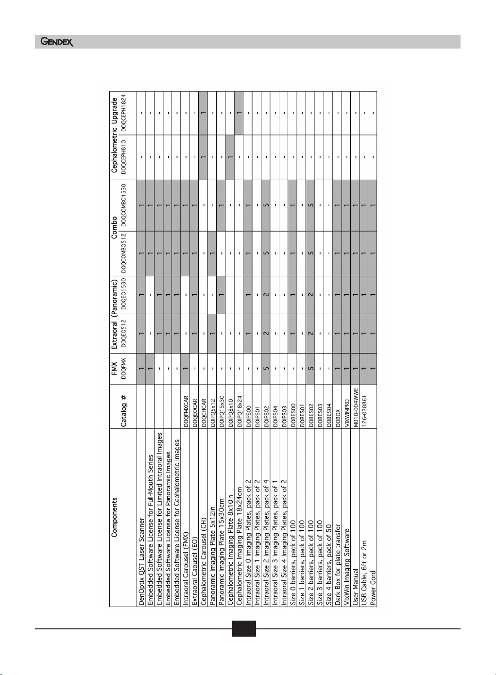
Table of models and components
Gendex DenOptix® QST
User and Service Manual
16
Doc # M010-004WWE July 2005
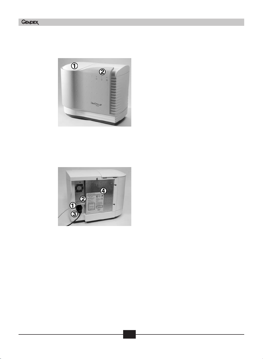
DenOptix QST laser scanner
Figure 4-1 Scanner front view
Figure 4-2 Scanner rear view
Gendex DenOptix® QST
1) Carousel well and lid. The lid has a locking mechanism that engages during scanning and loss of
power (see Section 7.3 or handling procedure).
The carousel, with imaging plates attached, is
inserted into the carousel well for scanning. The
carousel lid must be in the closed position prior to
scanning. The scanner will not operate with the lid
open.
2) LED indicator lights with graphic symbols.
The lights show the current status of the system.
Green — Ready to scan
Yellow Blinking – Scanning
Red — Error
1) DenOptix QST scanner power entry module with
switch and fuses
2) USB 2.0 connector. A USB 2.0 cable (provided)
connects the DenOptix QST scanner to the CPU’s
USB 2.0 port.
3) Power cord socket. The power cord (provided) will
be connected from this point to a grounded main
outlet.
4) Scanner label
User and Service Manual
17
Doc # M010-004WWE July 2005
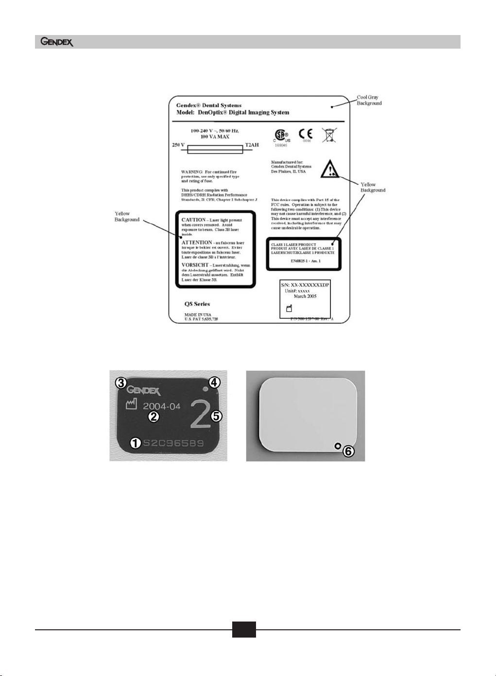
Scanner label
Gendex DenOptix® QST
User and Service Manual
Figure 4-3 Intraoral imaging plates
Rear (Black)
1) IP serial number for tracking purposes
2) Date of manufacture
3) Available from Gendex Dental Systems
4) Solid orientation dot
5) IP size indicator. Shows the equivalent film size
6) Orientation circle. Visibly shows on final radiograph for faster orientation
Front (Blue)
18
Doc # M010-004WWE July 2005
Gendex DenOptix® QST
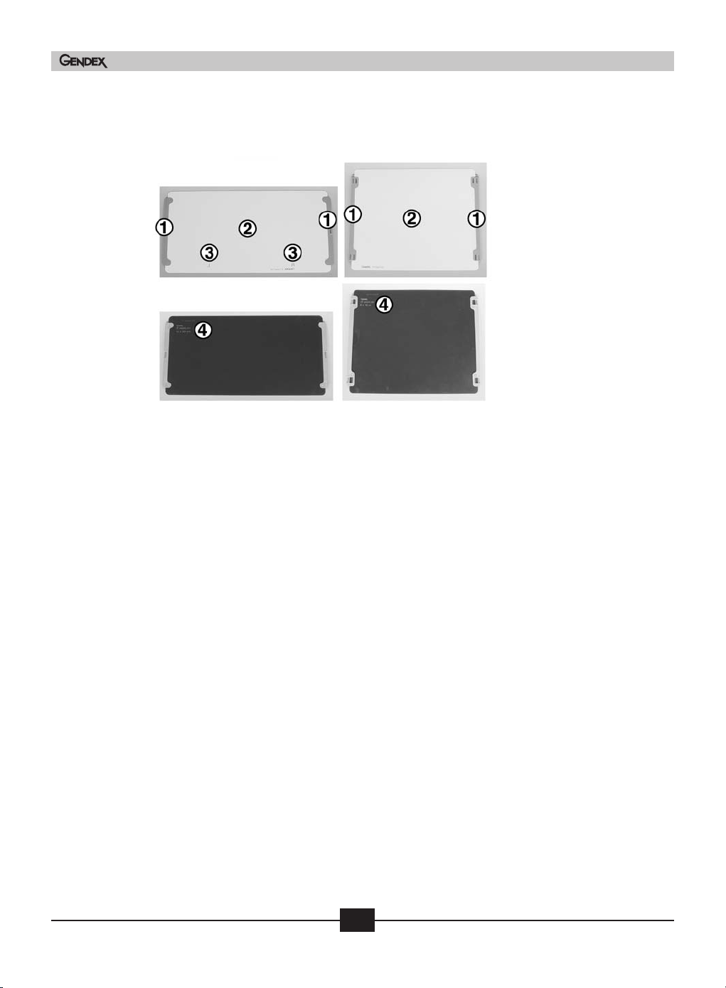
Figure 4-4 Panoramic and cephalometric imaging plates
Panoramic Cephalometric
Front (Blue)
Rear (Black)
1) Plastic mounting strips used to hold panoramic imaging plate onto the carousel
2) Active imaging area, white color
3) Patient left ( ) and right ( ) side indicators
4) General information that includes:
• Available from Gendex
• Date of manufacture
• Imaging plate size
• IP serial number
L
R
User and Service Manual
19
Doc # M010-004WWE July 2005

Figure 4-5 Carousels
Gendex DenOptix® QST
Intraoral (QFMX)
Extraoral QEO/Ceph (QCH)
1) Top of the carousel. For the EO/CH carousels, the knob will be positioned based upon
whether or not a Pan or Ceph is being scanned. If a Pan or Ceph is loaded, turn the knob
towards the mark indicating a Pan or Ceph. If no Pan/Ceph plate is loaded, rotate the knob
to the “no Pan or Ceph” position.
2) I/O imaging plate holders. The intraoral carousel can hold up to 39 I/O imaging plates at
one time: 20 size 2, 9 size 1, 8 size 0, 2 size 3.
3) Panoramic imaging plate retaining device. The panoramic carousel can hold either the
5x12 in or the 15x30 cm imaging plate.
4) Cephalometric imaging plate retaining device can hold either 8x10 in or 18x24 cm.
5) I/O imaging plate holders on the back of the Extraoral (EO) and Ceph (CH) carousel.
The carousel can hold up to four size 2, two size 0 and one size 4 imaging plates.
Figure 4-6 Disposable barrier envelopes
User and Service Manual
Front (Blue)
Back (Clear)
1) The front of the barrier envelope is blue. This is the side that should face the X-ray tube.
2) Barrier envelope adhesive strip. When this is removed, the envelope can be sealed and provides protection from cross-contamination
20
Doc # M010-004WWE July 2005

4.4 Computer requirements
Minimum Computer Requirements Recommended
CPU Speed 800 MHz Pentium 4 2.4 GHz
Operating system Microsoft® Windows® 2000 /XP Pro Microsoft® Windows® XP Pro
SP2 SP2
RAM 128 MB 256+ MB
Hard Drive 6 GB 40+ GB
USB port USB 2.0 USB 2.0
Monitor S-VGA with 0.25mm/0.26mm S-VGA with 0.25mm/0.26mm
dot pitch dot pitch
Video Display Adapter 4 MB RAM, 800 x 600 display, 8+ MB RAM, 1024x768
true color true color
Keyboard, Mouse Standard Standard
Backup Device Highly recommended
Printer Recommended (see appendix C)
1
To be evaluated based on the number of images taken, and the image file size used by the imaging software.
4.5 Electrical requirements
Gendex DenOptix® QST
1
Voltage 100-240 V AC 50/60 Hz power supply auto-senses the input voltage.
Power 110 watts maximum
Power Cord Standard line cord provided (Medical Grade for 115V)
4.6 Compliance to standards
The DenOptix QST System conforms to the following standards:
Standard Title
UL 60601-1 Medical Electrical Equipment, Part 1: General requirements for safety
1 CFR Chap
2
Subchapter J
MDD 93/42/ECC
CAN/CSA-C22.2 Medical Electrical Equipment, Part 1: General requirements for safety
No. 601.1
IEC 6060
IEC 6060
IEC 60825-1 Safety of Laser Products
ISO 1
ISO 14971 Risk Analysis
ter I Performance Standard for Light-Emitting Products
opean Medical De
Eur
1-1
1-1-2
485 Medical devices- Quality management systems
3
Medical Electrical Eq
Medical Electrical Eq
ety- Collateral standard; Electromagnetic Compatibility
saf
vice Directive (CE Mark)
uipment, Par
uipment, Par
t 1: General requirements for safety
t 1: Gener
uirements for
al req
User and Service Manual
21
Doc # M010-004WWE July 2005

4.7 Installation
The DenOptix QST System is designed to be installed by a qualified equipment professional
from your local dental dealer. Ask your local dental dealer for more information.
We do not recommend that an untrained person try to install and configure the system.
4.8 Site selection
The DenOptix QST scanner can be located almost anywhere in the dental office. The site
you pick should have:
• Subdued lighting conditions. You should have the ability to turn down/off the lights and
block sunlight with blinds. The area to be used for mounting imaging plates should not
exceed 20 lux as measured on a light meter. This will give you about one minute to mount
all of your imaging plates without encountering excess signal fading. If you cannot measure the light in the room where you wish to mount the imaging plates, you should turn
off the room lights, close all blinds and leave the door open just enough so that you can
see to mount the imaging plates. This should make the light level about 10-20 lux. If you
need more than one minute, refer to appendix B.
Gendex DenOptix® QST
User and Service Manual
• A stable, flat countertop large enough to hold the scanner plus provide a working area. We
suggest a minimum of 189x369 in. (46x92 cm). The computer does not need to be on the
countertop, but must be within the length of the USB 2.0 cable (9ft or 3m provided). The
countertop must be able to hold the weight of the unit or a minimum of 60 lbs (27 kg).
• Access to a standard grounded electric outlet.
• Enough room to allow the operator to mount imaging plates and use the computer
effectively.
• Do not position the DenOptix QST scanner in a dusty environment. Excessive dust levels
can result in additional scanner service, beyond normal service intervals.
ou choose to put the system in your darkroom, please prepare the site by:
If y
• Removing all old film processing equipment and plumbing.
• Remove the safelight filter and adjust the intensity of the light by lowering the bulb
wattage until the intensity of the light around the scanner is 20 lux or less.
• We recommend that you keep the light off and the door open when mounting imaging
plates to the carousel. The light from the open door will allow you to see enough to mount
the imaging plates but will not adversely effect the image.
22
Doc # M010-004WWE July 2005

4.9 Unpacking the unit
The DenOptix QST System is shipped in one box. Completely unpack the box and save it in a
safe, dry location. You may need to repack the unit for shipping if you ever encounter a maintenance outage, or relocate your office.
Inventory the contents of the box according to the “Table of Models and Components”
(Section 4.3) and ensure that you have all the components for your DenOptix QST system as
they’re listed in the Table. If any items are damaged or missing, contact your dental dealer
immediately.
Gendex DenOptix® QST
Figure 4-7
Scanner, 1 each
Figure 4-10
Disposable Barrier Envelopes
500 Size 2 (FMX and Combo
units), 200 Size 2 (EO units)
Figure 4-12
15x30 cm or 5x12 in Imaging
Plate, 1 each (EO and Combo
units)
Figure 4-8
Intraoral Carousel 1
each (FMX and
Combo units)
Figure 4-11a
Size 0 Imaging Plates,
2 each (EO and
Combo units)
3
e 4-1
igur
F
4 cm or 8x1
8x2
1
Plate, 1 each (Included with
hase of Ceph kit)
purc
0 in Imaging
Figure 4-9
EO/CH Carousel 1 each
(EO, Combo units,
and Ceph upgrade)
Figure 4-11b
Size 2 Imaging Plates,
20 each (FMX and
Combo units), 8 each
(EO units)
User and Service Manual
23
Doc # M010-004WWE July 2005

Gendex DenOptix® QST
Figure 4-14
Power Cord, 1 each
Figure 4-15
User Manual and
Installation Guide
(Software and Hardware),
1 each
4.10 Hardware setup and connections
NOTE: Before you start the hardware setup, ensure that you have an acceptable computer as outlined in Section 4.4. The computer must have a USB 2.0 port available.
Step 1: Pick a location using the guidelines from Section 4.8.
Step 2: Set up the computer and monitor per the manufacturer’s recommendations. Use an
ergonomic setup to minimize repetitive motion injuries.
Step 3: Turn the power on to the monitor and computer.
Step 4: Connect the device end of the USB 2.0
cable to the USB 2.0 connector on the
back of the DenOptix QST scanner.
Connect the scanner to a grounded
power outlet. Make sure the other end
of the USB 2.0 cable is connected to the
USB 2.0 port on the computer.
Step 5: Connect the computer to a network
if desired. Refer to your Imaging
are User Manual and Installation
tw
Sof
Guide for more information on how to
configure the Imaging Software in a
twork.
ne
tep 6: Turn the power on the scanner. The green light on the scanner should be lit at this
S
he trouble shooting guidelines in Section 7.3.
w t
time. If it is no
Step 7: After the Windows operating system is loaded, a message indicating that a “New
Hardware” has been found will appear. Follow the on-screen instructions to finalize the installation.
t, follo
Figure 4-16
USB 2.0 cable (6 ft, 2 m)
1 each
User and Service Manual
24
Doc # M010-004WWE July 2005

4.11 Network installation
Refer to your network/computer professional for network installation, configuration and
maintenance. Refer to your Imaging Software User Manual and Installation Guide for more
information on how to configure the Imaging Software in a network.
Gendex DenOptix® QST
User and Service Manual
25
Doc # M010-004WWE July 2005

Gendex DenOptix® QST
User and Service Manual
26
Doc # M010-004WWE July 2005

System operating instructions
5.1 Preparing your current X-ray equipment
The DenOptix QST System produces X-ray images of high quality and low noise yet offers a
dose reduction in intraoral surveys up to 80% of the dose required for D-speed intraoral film.
More details on how this technology works can be found in appendix A. Almost any intraoral or panoramic X-ray unit can be used with the DenOptix QST system. There is no need to
purchase a new one.
The imaging plates produce excellent diagnostic images over a wide range of exposures. With
the DenOptix QST system, it is possible to get diagnostic images at the same exposure time
you use for X-ray film or as much as 80% reduction of the dose required for D-speed film.
This means that it is more difficult to over- or under-expose an image. We recommend, however, that you start with the exposure times outlined in the table below.
5
User and Service Manual
Intraoral equipment
Exposure times indicated hereunder are estimates that must be verified and adjusted
depending on specific and actual local conditions, e.g. supply voltage, X-ray tube yield, timer
accuracy, beam filtration, etc.
27
Doc # M010-004WWE July 2005

Gendex DenOptix® QST
Intraoral equipment suggested exposure times,
in seconds and impulses
DC SUPPLY 60kV 65 kV 70 kV
AC SUPPLY 50 kV 60 kV 65 kV 70 kV 75 kV
Lower incisor/cuspid 0.32 sec. 0.25 sec. 0.16 sec. 0.16 sec. 0.12 sec.
19 impulses 15 impulses120 imp. 10 imp. 7 imp.
Lower premolar 0.40 sec. 0.32 sec. 0.16 sec. 0.16 sec. 0.12 sec.
24 imp. 19 imp. 25 imp. 10 imp. 7 imp.
Lower molar 0.50 sec. 0.40 sec. 0.20 sec. 0.20 sec. 0.16 sec.
30 imp. 24 imp. 32 imp. 12 imp. 10 imp.
Upper incisor/cuspid 0.40 sec. 0.32 sec. 0.16 sec. 0.16 sec. 0.12 sec.
24 imp. 19 imp. 10 imp. 10 imp. 7 imp.
Upper premolar 0.50 sec. 0.40 sec. 0.25 sec. 0.20 sec. 0.16 sec.
30 imp. 24 imp. 15 imp. 12 imp. 10 imp.
Upper molar 0.64 sec. 0.50 sec. 0.32 sec. 0.25 sec. 0.20 sec.
38 imp. 30 imp. 19 imp. 15 imp. 12 imp.
Reference conditions:
• Adult patient
• Anodic current 7 mA.
• Source to Detector Distance SSD = 250 mm (10 inches)
• Total (inherent) filtration 2 mm Al equip.
User and Service Manual
Unless the image is grossly over- or under-exposed, image density can be corrected by subsequent software processing (contrast/brightness — see Imaging Software User Manual and
Installation Guide).
1
One impulse is equal to .017 sec. at 60 Hz. The recommended number of impulses can be
adjusted as necessary for proper exposure, resulting in adequate image density and contrast
and low noise gratuity.
Panoramic/cephalometric equipment
The DenOptix QST system requires no adjustments to the panoramic/cephalometric exposure
settings (kV, mA or time). The DenOptix QST system can be used with almost any existing
panoramic/cephalometric unit, regardless of age or manufacturer.
The use of a cassette without an intensifying screen is highly recommended. If you choose
to use a cassette with an intensifying screen, you must at a minimum remove the front
t a low quality image due
screen. If t
ensifying screens are no
he int
t remo
ou will g
ed, y
v
to the shielding effect from a decreased dose reaching the imaging plate. To remove the
intensifying screens, follow the directions below.
28
e
Doc # M010-004WWE July 2005

• If you have a soft vinyl cassette, simply remove both intensifying screens from the cassette.
• If you have a hard sided cassette, remove intensifying screens (these are usually glued).
• Cassettes without intensifying screens are also available from Gendex.
Contact your local dental dealer or the panoramic/cephalometric equipment manufacturer
for additional assistance.
5.2 Erasing the imaging plate
Imaging plates should be erased just prior to use. Scanning an imaging plate does not erase
all the image information. To completely erase the imaging plate, expose the front surface
(blue or white in color) to direct, intense light for 2 minutes. Fluorescent light is highly
recommended.
An effective way to erase the imaging plate is to use a lightbox such as the RINN® Universal
Viewer. We recommend fixing the lightbox under a cabinet. Make sure to lay the imaging
plate down with the ACTIVE SIDE UP (blue or white face) facing the lightbox shining down.
Expose the plates to light for 2 minutes.
Gendex DenOptix® QST
Alternatively, place the imaging plates within 8 inches of a lamp equipped with a lit
100-watt bulb for two minutes, minimum. The imaging plates are now completely erased and
are ready for reuse.
To avoid scratching the imaging plates, DO NOT lay the imaging plate active (“blue or white”)
face down on a lighbox.
Note: Erasing time will vary depending on the quality and intensity of the erasing light. For
more detailed information, see appendix B.
User and Service Manual
29
Doc # M010-004WWE July 2005

5.3 Infection control
Prior to use, the DenOptix QST I/O imaging plates must be placed in barrier envelopes to
minimize the possibility of cross-contamination. With proper application and use of the
barriers, it will not be necessary to routinely cold sterilize the imaging plates. After erasing
the imaging plates, follow these directions:
Gendex DenOptix® QST
Figure 5-1
Insert the imaging plate into the barrier
envelope, ensuring that the black side of the
imaging plate can be seen through the clear
side of the barrier envelope. Pay careful
attention to the location of the orientation
dot.
Figure 5-2
With the imaging plate completely inserted,
seal the envelope by removing the adhesive
strip and pressing the envelope closed. The
imaging plate is now protected and can be
used intraorally.
User and Service Manual
30
Doc # M010-004WWE July 2005

5.4 Taking an X-ray
Intraoral imaging
Gendex DenOptix® QST
Figure 5-3
Ensure the computer, monitor and DenOptix
QST scanner are switched on and properly
connected. The green LED indicates that the
system is ready to scan.
Figure 5-4
Launch your imaging software. Refer to your
Imaging Software User Manual for details
(VixWin shown).
Figure 5-5
Place an erased I/O imaging plate in the
sealed barrier envelope and position in the
patient’s mouth. Make sure that the blue
side (front of the barrier envelope and,
therefore, front of the imaging plate) is
toward the X-ray source. Wear appropriate
gloves and protective attire.
We recommend the use of a positioning
device. The orientation dot should be posi-
tioned toward the occlusal surface for periapical projections. Fold back the barrier prior to inserting it into the positioning device. This
will ensure that the imaging plate is firmly held in place. Ensure that the imaging plate (not
the barrier) is in the center of the aiming ring. Expose the X-ray in the usual manner.
Exposure settings should be in accordance with Section 5.1.
User and Service Manual
31
Doc # M010-004WWE July 2005

Gendex DenOptix® QST
Figure 5-6
Wearing gloves, remove the imaging plate in the
barrier envelope from the patient’s mouth. Wipe off
any excess saliva with a paper towel. Disinfect the
barrier envelope by dipping it into a cold sterilant
solution, if desired.
After each exposure, open the barrier envelope at
the “V” cut in the center of the packet, with a
steady pull, and let the plate fall into the transfer
container (Dark Box provided with the system).
At the end of the intraoral examination, remove and dispose of gloves and move to a semidarkened room or area (see Section 4.8). Remove lid and begin the process of loading the
imaging plates.
Do not touch the transfer container with contaminated gloves.
Figure 5-7
Remove your gloves and wash any powder from
your hands. Mount the I/O imaging plates onto
the carousel by sliding the right side of the imaging plate into the correct size I/O mounting hole
in the carousel. Ensure that the blue side faces
out.
User and Service Manual
32
Repeat until all I/O imaging plates are mounted.
Figure 5-8
Open the carousel well cover on the DenOptix QST
scanner and insert the carousel. Close the lid. You
are now ready to scan your I/O imaging plates, as
outlined in Section 5.5.
Doc # M010-004WWE July 2005

Gendex DenOptix® QST
Panoramic/cephalometric imaging
Figure 5-9
Place the erased panoramic or cephalomet-
ric imaging plate into the cassette with the
white side pointed toward the tubehead.
Insert the cassette into the panoramic or
cephalometric unit and expose in the usual
manner.
Figure 5-10
With the EO/CH carousel you can scan 4 #2
size imaging plates, 2 #0 size and 1 #4 size
imaging plate. Follow the steps previously
outlined for intraoral imaging but mount the
I/O imaging plates on the panoramic
carousel.
When scanning a Pan or Ceph plate, rotate the knob in the direction of Pan or Ceph. When
no pan or ceph is loaded, rotate the knob in the direction of “NO PAN or CEPH”.
User and Service Manual
33
Figure 5-11
In a semi-darkened room (see Section 4.8),
open the cassettes. With the white surface
pointed away from the carousel, insert one
side of the imaging plate under the edge of
the panoramic or cephalometric imaging
plate clip. Push with your thumbs until you
hear a “click.” NOTE: If the IP does not click
into place, slide the IP to one side then the
other until it clicks into place.
Panoramic shown.
Doc # M010-004WWE July 2005

Gendex DenOptix® QST
Figure 5-12
Wrap the imaging plate around the carousel
and push the free end under the edge of the
other clip. Push until you hear a “click.”
Panoramic shown.
Figure 5-13
Open the carousel well cover on the DenOptix
QST scanner and insert the carousel. Close the
cover. You are now ready to scan your
panoramic or cephalometric imaging plate.
User and Service Manual
34
Doc # M010-004WWE July 2005

5.5 Scanning the imaging plate
plates by simply clicking the appropriate plate. The plates in black will be skipped (not
acquired).
Gendex DenOptix® QST
Figure 5-14
Once the scanner has been loaded and
the patient file has been opened, click on
the scanner icon on the imaging software
toolbar. The software will automatically
sense whether an FMX, EO or Ceph
carousel is loaded.
Figure 5-15
When you scan a carousel, you can select
from several options (subject to change,
depending on the imaging software
used).
It is possible to select how many plates to
scan, and what size.
Plates can be arranged and saved to customized templates. You can select the
User and Service Manual
You can choose between 150, 300, and 600 dpi. Scan time will be longer as you chose higher dpi. Make the appropriate choice by clicking on one of the combinations and then clicking on “scan”.
NOTE: The more specific you are, the faster the scan time will be. For example, scanning the
top row takes less than 30 seconds at 300 dpi. Scanning 20 imaging plates at 300 dpi. takes
approximately 75 seconds.
Figure 5-16
emplates scanned will be
ou can also sa
6. Y
Doc # M010-004WWE July 2005
ve templates
35
The last four t
ed for quick retrieval by simply clicking
v
sa
the “T” in the lower right as shown in
igure 5-1
F
by selecting “templates” and save. After
you name the template, you can retrieve
this template by selecting “Templates” and
“Load”. A window box will appear requesting the name of the template to load.

Gendex DenOptix® QST
Figure 5-17
The procedure for scanning a
panoramic/cephalometric plate is the
same as for the intraorals.
It is possible to select how many
plates to scan, and what size. As
with intraorals, you can choose
between 150, 300, and 600 DPI.
Scan time will be longer as you
choose higher DPI. To switch
between panoramic and cephalometric, click on the “P” or “C” symbol
in the lower right hand corner. To
change between inch and metric,
click “IN” or “CM”.
Choose your imaging plates by clicking on each of the imaging plate
boxes you want to acquire and then
clicking on “scan”.
The plates in black will be skipped (not acquired).
To save the template, click on the template menu choice and save.
When the scan is complete, the I/O images will appear on the screen.
Note: if an error occurs during the scan, the scanner will stop. Follow the troubleshooting
guidelines to start scanning again. If the resulting image is not diagnostic, erase the imaging plate and start again.
User and Service Manual
36
Doc # M010-004WWE July 2005

5.6 Preparing for the next patient
Once scanning is complete, it is time to get ready for the next patient.
Cross-contamination
There is no reason to routinely sterilize imaging plates unless you believe they have been contaminated. If an imaging plate has touched a contaminated surface, wipe it gently with lintfree gauze dampened with a cold sterilant as recommended by the manufacturer. DO NOT
SOAK. Two percent (2%) Gluteraldehyde solutions will not damage the imaging plate if used
as described. IMAGING PLATES CANNOT BE AUTOCLAVED.
If a carousel has touched a contaminated surface, the intraoral imaging plate holders should
be removed (see Section 7.1) and wiped with a cold sterilant solution. The remainder of the
carousel can be sprayed with an aerosol disinfectant or soaked in a cold sterilant solution.
If the outside of the DenOptix QST scanner has been touched by a contaminated surface, it
must be cleaned. BEFORE PROCEEDING, TURN THE SCANNER OFF AND DISCONNECT FROM
THE POWER OUTLET. The outside of the scanner can now be wiped with a towel dampened
with cold sterilizing solution and then allowed to air dry. DO NOT SPRAY OR SOAK THE SCANNER. If necessary, wipe the inside of the carousel well with a cloth very lightly dampened
with cold sterilizing solution. NEVER SPRAY THE INSIDE OF THE CAROUSEL WELL. Be careful
not to allow solvent into the DenOptix QST scanner, which could damage the electronics
inside. Allow to air dry before connecting the power cord or turning the unit on.
Gendex DenOptix® QST
User and Service Manual
It is the operator’s ultimate responsibility to ensure that correct infection control procedures,
consistent with those recommended by the Board of Dental Examiners, are followed and that
effective cold sterilant and disinfecting sprays are used.
Follow the steps in Sections 5.2 and 5.3 to erase the imaging plate and protect it from crosscontamination. You are now ready to take an X-ray on the next patient.
37
Doc # M010-004WWE July 2005

5.7 Turning the DenOptix QST system on and off
The DenOptix QST System is designed to be left on continuously. The laser is only operational
while the unit is actually scanning. If you wish to turn the system off, please remove the
carousel and use the following procedure.
1. Wait until any scan in progress is complete and the green light is on.
2. Save any changes you have made and close down the imaging software (for example
VixWin Pro software). To protect your data, frequently back-up your files.
3. Turn the power switch in the back of the scanner to the “Off” position.
4. Turn off all computer components following any instructions from the manufacturer.
If you live in an area of frequent thunderstorms or variable line voltages, you may want to
turn the unit off on a more regular basis. An uninterruptible power supply (UPS) is recommended for areas with power quality issues.
Gendex DenOptix® QST
User and Service Manual
38
Doc # M010-004WWE July 2005

Software operating
instructions
The DenOptix QST imaging systems can operate with different imaging software. For
example, VixWin imaging software from Gendex optimizes digital X-ray images from the
DenOptix QST systems. Please refer to your Imaging Software User Manual and Installation
Guide for detailed instructions.
6
User and Service Manual
39
Doc # M010-004WWE July 2005

User and Service Manual
40
Doc # M010-004WWE July 2005

Maintenance procedures
The DenOptix QST System is designed for many years of trouble-free operation. It is manufactured from the highest quality components to ensure excellent performance. Maintenance
that can be performed by the operator is minimal.
7.1 Cleaning the system
If the scanner, imaging plates or carousel becomes contaminated, clean in accordance with the
directions given in Section 5.6. If, however, a component merely becomes soiled, clean as follows:
Cleaning the scanner
Turn off the DenOptix QST scanner, as described in Section 5.7, before cleaning. Wipe the
outside surfaces with a paper towel dampened with a cold sterilant solution or household,
non-abrasive cleaner (window cleaner works well). DO NOT SPRAY OR SOAK THE SCANNER.
Wipe the inside of the carousel well with a very slightly damp cloth. Be careful not to allow
running or dripping solvents into the DenOptix QST scanner. This could cause damage to the
electronics inside. Allow to air dry before plugging in or turning back on.
7
User and Service Manual
Cleaning imaging plates
Imaging plates should be handled carefully. For the best images, take care not to scratch them
and k
eep them dust-free. Use the following procedure to clean them:
on gauze (not cotton balls). Gently wipe the cotton gauze over the
tt
. Use lint-free, 1
1
dry imaging plate surface. Wipe back and forth and then in a circular motion.
2. To clean any remaining stains, dampen the gauze in anhydrous (water-free) isopropyl
alcohol and wipe using t
3. Completely dry the surface by wiping with another piece of cotton gauze. Ensure that the
imaging plate is completely dry before use.
00% co
he same motion as above.
41
Doc # M010-004WWE July 2005

Cleaning the carousel
Gendex DenOptix® QST
Figure 7-1
Remove the intraoral imaging plate holder from
the carousel by removing the three screws
along the vertical plastic retention piece. After
removing the three screws, the intraoral plate
holder will come free from the carousel.
Figure 7-2
Spray the soiled surfaces of the imaging plate
holder and carousel with a general household
non-abrasive cleaner or soap and water. Do not
use strong alkaline or ammonia based cleaners.
Wipe clean and allow to air dry.
User and Service Manual
42
Figure 7-3
Insert the dry imaging plate holder under the
vertical plastic retention piece on the carousel.
Slightly tighten the screws to hold the first side
in place. Take the other side of the intraoral
plate holder and place under the plastic retention piece and tighten the screws.
Doc # M010-004WWE July 2005

Gendex DenOptix® QST
Cleaning the EO/CH (panoramic and cephalometric) carousel
Figure 7-4
To clean the EO/CH carousel, you will follow similar
steps to the intraoral carousel. Remove the carousel
imaging plate holder by removing the three screws of
the plastic retention piece on both sides of the
carousel. The imaging plate holder will easily come
free.
Spray the carousel with a general household nonabrasive cleaning solution. Do not use strong alkaline
or ammonia based cleaners.
Wipe clean and allow to air dry. If the intraoral imaging plate holder is soiled, remove it by removing both
vertical plastic retention pieces by removing the three
screws on each side and following the same instruc-
tions as for the intraoral image plate holder cleaning.
Clean with the general household non-abrasive spray or soap and water. Allow to dry completely before re-assembling. Re-assemble by placing one side of the imaging plate holder
under the plastic retention device and tighten screws. Repeat step on the other side of the
imaging plate holder, replace plastic retention device and tighten the three screws.
User and Service Manual
43
Doc # M010-004WWE July 2005

7.2 Operator maintenance
Scanner maintenance
The only part of the DenOptix QST scanner that may require operator maintenance is the fuse.
If you experience any other service-related problem, contact your local Gendex dealer. Follow
these directions to change the fuse.
Gendex DenOptix® QST
Figure 7-5
Turn the DenOptix QST scanner off as per
Section 5.7. Unplug the power cord and USB 2.0
cable.
WARNING: To avoid possible electrical shock,
ensure that the power cord is unplugged.
Figure 7-6
Insert a small, flat tipped screwdriver into the
top of the fuse cover on the back of the scanner.
Pry the top of the connector open.
igure 7-7
F
Remove the fuse holder. Change both fuses.
Ensure that new fuses meet the following specifications: 250 V, 2 amp, Time Lag, High Breaking
Capacity. Insert the fuses, REF 5101-0005, into
the fuse holder.
User and Service Manual
44
Doc # M010-004WWE July 2005

Gendex DenOptix® QST
Figure 7-8
Insert the fuse holder and close the cover. Plug
the power cord back in and turn the system on
as outlined in Section 5.7.
Carousel maintenance
The carousel from the DenOptix QST scanner can be maintained by the operator. If the intraoral imaging plate holder on an intraoral, panoramic or cephalometric carousel becomes
damaged, it can be replaced by the operator. Order a replacement holder from your local
Gendex dealer. The damaged holder can be removed and the new holder mounted as
described in Section 7.1.
Imaging plate maintenance
The DenOptix QST imaging plates have no operator serviceable parts.
Lubrication
The DenOptix QST Digital System might occasionally require lubrication. If the scanner should
start to squeak during scanning, please contact your local Gendex dealer. Do not position
the DenOptix QST scanner in a dusty environment. Excessive dust levels can result in additional scanner service, beyond normal service intervals.
User and Service Manual
45
Doc # M010-004WWE July 2005

7.3 Troubleshooting
Gendex DenOptix® QST
Trouble
No power
No green light
Lid is Locked
Probable cause
Scanner not plugged in
Blown fuse
Main power switch or
power supply is bad
Outlet does not have
power
System is scanning
Power Failure or lack of
power.
Corrective action
Check power cord at outlet and
at the connection on the back of
the scanner. Turn on the scanner, then turn on the computer
and monitor.
See Section 7.2
Call your service representative.
Ensure that the outlet is
grounded and has power.
Wait for scanning to end before
attempting to open the lid. DO
NOT OVERIDE THE LOCKING
MECHANISM DURING SCANNING.
Unplug the scanner from the
power source. Slide a thin tool
or credit card into the gap
between the lid and the scanner
housing and simply depress the
lock. You can then remove the
carousel
User and Service Manual
Red, Green and/or Yellow
LED(s) do not work; system operates normally
Defective LED Call your service representative
46
Doc # M010-004WWE July 2005

Gendex DenOptix® QST
Trouble
The Scanner does not initialize when the software
is opened
Probable cause
The scanner has not
been turned on
The lid on the carousel
well is open
The USB 2.0 cable
between the scanner
and computer is loose or
defective.
The computer does not
recognize that the scanner is connected or the
scanner has not been
added to the Device
Manager
There is a hardware
problem with the
DenOptix QST scanner.
Corrective action
If the green power indicator light
is off, switch on the DenOptix
QST scanner per Section 5.7.
Close the lid.
Reconnect the cable. Check for
tightness. Swap with a known
good cable if possible.
Turn off the scanner and
re-install the DenOptix QST
systems software driver.
Turn the unit on.
Call your service representative
User and Service Manual
After scanning, no
image appears on the
monitor
There are no imaging
plates on the carousel.
The imaging plate is
mounted backwards on
the carousel.
The imaging plate was
erased prior to scanning.
Hardware failure.
X-ray source failed.
47
Ensure that the exposed imaging plate is properly mounted
for scanning
The imaging plates are to be
mounted with the white or blue
surface visible. Turn incorrectly
mounted plates around and
rescan
Ensure that imaging plates are
mounted under low light conditions as outlined in Section 4.8
Call your service representative.
Call your service representative.
Doc # M010-004WWE July 2005

Gendex DenOptix® QST
Trouble
Image is too dark
Image contains ghost
images or shadows
Probable cause
Imaging plate has been
overexposed
Imaging plate was not
completely erased.
Imaging plate was
exposed with the back
of the IP facing the
tubehead You may
notice the writing from
the back of the plate
on the image.
Corrective action
Adjust brightness with software.
If this is not possible, retake
image at lower exposure. See
exposure guidelines Section 5.1.
Increase the amount of time
that is used to erase plates.
Alternatively, increase the intensity of the light source. To test if
an imaging plate is completely
erased, simply mount an erased
plate on a carousel and scan it.
If no image is obtained, your
procedure is effective at completely erasing imaging plates.
Insure the imaging plates are
inserted properly into the barrier envelope and the proper orientation to the X-ray source is
maintained
User and Service Manual
Imaging plates have
been stored in barrier
envelopes for too long
a period.
Partial erasure of the
image due to exposure
to light during handling
of the imaging plates.
48
Do not store imaging plates in
barrier envelopes for more than
one week.
Do not leave exposed imaging
plates in well-lit areas. Even in
the barrier envelope, some light
penetrates and can partially
he imaging plates.
ase t
er
Transfer imaging plates from
their protective barriers to the
DenOptix QST scanner as quickly
as possible using the Dark Box
(within one hour of exposure).
Doc # M010-004WWE July 2005

Gendex DenOptix® QST
Trouble
Image shows artifacts
The barrier envelope did
not seal properly
Imaging plates fall out
into the DenOptix QST
scanner carousel well
Probable cause
The imaging plate surface is not clean and
has dust, powder or
stains on it. The surface
may be scratched.
The imaging plate was
removed from the
panoramic cassette too
quickly, which resulted
in a static discharge
After the protective strip
covering the adhesive on
the barrier envelope was
removed, the adhesive
was touched or picked
up dirt.
The imaging plates
have not been loaded
properly. See Section 5.4
for more information.
Corrective action
Clean the imaging plate as outlined in Section 7.1. If the plate
is scratched or stained, do not
use the plate again.
Clean the imaging plate with
anhydrous isopropyl alcohol
AND remove from cassette
more slowly.
Immediately seal the barrier
envelopes after removing the
adhesive strip.
Practice loading erased imaging
plates in full daylight until you
become familiar with the loading procedure. You will hear a
“click” when the panoramic
screen is loaded properly.
User and Service Manual
Extraoral plates don’t
stay on the carousel
during scanning
The red light stays on
and the scanner stops
Broken clips Replace broken clips
Hardware failure
49
Call your service representative
Doc # M010-004WWE July 2005

Gendex DenOptix® QST
7.4 Disposal of waste materials and inoperative parts
Disposal regulations vary from country to country. Therefore, it is difficult to give specific
instructions on the disposal of DenOptix QST waste materials and inoperative parts. In general, we believe the following guidelines to be true.
Material Items Recycle? Comments
Plastic Barrier Envelopes No Dispose of with other
Carousel Latches No non-recyclable plastic items.
Holders for I/O Plates No
Aluminum Housing, Optic Module Yes Remove all non-aluminum
Carousels Yes parts before recycling.
Scan Engine Frame Yes
Carriage, Optic Module Ye s
Storage Phosphors I/O Imaging Plates No Contain barium, which may be
Panoramic Imaging Plates No regulated. Contact your local
Ceph. Imaging Plates No Gendex for more information
on what to do with damaged
imaging plates.
Other Materials All Others No All other materials should be
sent to a landfill.
User and Service Manual
50
Doc # M010-004WWE July 2005

Storage and shipment
8.1 Storage
The DenOptix QST System has been designed for long-term operation in a normal office environment. The system must be protected from adverse conditions such as excessive moisture, cold or
heat. If the system is to be stored for a long period of time, pack the unit in its original carton.
While in storage, keep at moderate temperatures and protect against moisture and humidity.
When you are ready to use the system again, unpack it and allow the scanner to come back to
room temperature. Then, follow the guidelines outlined in Section 5.
8.2 Shipment
8
User and Service Manual
The DenOptix QST System is designed to be shipped in its original shipping container by normal
commercial carriers. Ensure that the carousel has been removed from the scanner and that the
carousel well is empty.
If the system is to be moved long distances or under adverse conditions, it should be protected.
This can be accomplished by wrapping the DenOptix QST scanner in a plastic bag before putting
it in the original packing materials.
If you are shipping the scanner, it is necessary to park the optics module in the center of travel
prior to shipment. Contact your local Gendex rep for details.
51
Doc # M010-004WWE July 2005

Gendex DenOptix® QST
User and Service Manual
52
Doc # M010-004WWE July 2005

Warranty statement
DenOptix QST scanner
The DenOptix QST Scanner and Carousels are designed expressly for use in a dental office
environment and this warranty is not applicable to other uses. The scanner and carousels are
warranted against defects arising from faulty materials or workmanship for two (2) years from
date of purchase. Parts will be repaired or replaced at our option. The DenOptix QST Scanner
and Carousels must be installed and operated in accordance with the Gendex written instructions furnished with the unit.
DenOptix QST imaging plates
The DenOptix QST Imaging Plates are designed expressly for use with the DenOptix QST scanner. DenOptix QST Imaging Plates will be replaced if defective in manufacturing or packaging
only. With proper handling, DenOptix QST Imaging Plates are designed for years of effective
use. They can, however, be damaged if folded, creased, scratched or dented, and, therefore no
additional warranty is provided.
9
User and Service Manual
53
Doc # M010-004WWE July 2005

Gendex DenOptix® QST
User and Service Manual
54
Doc # M010-004WWE July 2005

Technical specifications
DenOptix QST scanner
Height 39.4 cm 15.5 in
Width 49.3 cm 19.4 in
Depth 27.4 cm 10.8 in
Weight (empty) 16 kg 35 lbs
Interface Cables USB 2.0 cables
Voltage 100-240 V AC
Frequency 50/60 Hz
Power 110 VA max.
Laser Classification Compliance per DHHS Radiation Performance Standards 21 CFR,
Ch I, Subch. J+EN60825 Class 1 Laser Device
Operating Conditions 15° to 35°C (59° to 95° F); 5%-95% RH NC
Storage and Shipping -40° to 70°C (-40° to 158°F)
Temperatures
Class I Grounded
For Indoor Use Only
Suitable for continuous operation
10
User and Service Manual
DenOptix QST intraoral imaging plates
Size 0 Size 1 Size 2 Size 3 Size 4
I/O dimensions 22x35 mm 24x40 mm 31x41 mm 27x54 mm 57x76 mm
Recommended Dose Significant reduction in relation to typical D-speed film depending
upon type of X
orage Store in their clear plastic shipping box, at room temperature
t
S
Operating and 18° to 35°C (64° to 95° F); 5%-80% RH NC
e Conditions
ag
or
t
S
-ray device.
55
Doc # M010-004WWE July 2005

Gendex DenOptix® QST
DenOptix QST panoramic/cephalometric imaging plates
Dimensions Pan: 5x12 in; 15x30 cm Ceph: 8x10 in; 18x24 cm
Recommended Dose Equal to standard panoramic systems equipped with rare-earth
intensifying screens (400 speed)
Storage Store in their clear plastic shipping envelope
Operating and 18° to 35°C (64° to 95° F); 5%-80% RH NC
Storage Conditions
User and Service Manual
56
Doc # M010-004WWE July 2005

Appendix
11.1 Appendix A: Storage phosphor technology
The DenOptix QST System produces high quality X-ray images at very low doses as compared
to intraoral X-ray film. The imaging plates in the DenOptix QST Systems are much more efficient at capturing X-ray energy than film. This means that the timer on your intraoral X-ray
source can be turned down to a very low level without affecting the image quality.
11
User and Service Manual
How storage phosphor imaging plates work
Each DenOptix QST Imaging Plate is made up of a very thin layer of tiny storage phosphor
crystals that are bonded together and coated on a flexible sheet of plastic. These storage
phosphor crystals have the ability to capture the energy of X-rays and store the pattern as a
ent image (see diagram).
lat
57
Doc # M010-004WWE July 2005

Gendex DenOptix® QST
In essence, they act as an “energy trap,” storing X-ray energy. The amount of energy stored
is directly proportional to the amount of X-ray energy the crystal was exposed to.
The DenOptix QST scanner further excites the phosphor crystals to an unstable state by
exposing them to a red laser. The phosphor crystals then release a blue light and return to
their stable ground state. The DenOptix QST scanner reads this blue light and, with the imaging software, produces an image.
This process does not completely erase the imaging plate. Some crystals remain as “energy
traps.” This information can be erased by exposing the imaging plate to light. A few seconds
of low levels of light will usually not effect the image quality. Once erased, the imaging plate
can be re-exposed and the process can begin again. With proper handling, DenOptix QST
Imaging Plates can be continually reused.
11.2 Appendix B: Lighting conditions for handling or erasing
imaging plates
Without light, storage phosphor imaging would not work. The red light from the laser
scanner excites the exposed imaging plates, causing them to emit blue light. After your
computer interprets the blue light and changes it into a digital image, light is used to erase
the residual information from the imaging plate.
User and Service Manual
Between X-ray exposure and scanning, however, one must be careful handling the imaging
plates. An imaging plate should never be removed from its protective barrier and exposed to
a strong source of light. This act would erase the latent image from the plate. Therefore, you
must load imaging plates onto the carousel under controlled lighting conditions. The recommendations below have been developed to ensure that you obtain excellent image quality.
Recommendations on lighting conditions for loading carousels
Fluorescent lights
If loading can be accomplished in less than 60 seconds, the fluorescent lighting in the area
should not exceed 20 lux. If loading will take longer than 60 seconds, the room conditions
o be dar
need t
Incandescent lighting
Incandescent lighting is not as efficient as fluorescent lighting at fading imaging plates. We
recommend lighting conditions of around 20 lux. Under incandescent lighting, however, you
have about 2 minutes to complete the loading process. If it takes longer than 2 minutes,
decrease t
ker. At 10 lux, the operator has about 5 minutes to accomplish loading.
0 lux.
he amount of light t
o 1
58
Doc # M010-004WWE July 2005

Gendex DenOptix® QST
Sunlight
Sunlight is efficient light for erasing imaging plates but it is not recommended that IPs are
left exposed to sunlight for extreme periods of time. Additionally, it is very difficult to judge
the intensity of sunlight. Loading carousels under sunlight must be avoided.
If you cannot darken your mounting area to 20 lux or less, contact your local Gendex
representative for suggested mounting times.
Recommendations on lighting conditions
for erasing imaging plates
In order to completely erase imaging plates, 99.5% of the image information must be
removed. Scanning only removes part of the information. To completely erase imaging plates,
follow the guidelines given below. It is important that you measure the light intensity with
a light meter at the point where the imaging plate will be positioned. The intensity of light
changes dramatically as you move away from the source. Erasing the imaging plates for
periods of time longer than suggested does not harm them. A good place to store your
imaging plates is under the erasing light source.
Fluorescent lights
We recommend using fluorescent lights for erasing imaging plates. A lightbox typically gives
off between 1000 and 5000 lux. Measure your lightbox and use the lowest value to determine the erasing time. At 1000 lux, an imaging plate will be erased in 1 minute. At 2000 lux
or more, 30 seconds is sufficient.
User and Service Manual
Incandescent lighting
At 1000 lux, an imaging plate will be erased in about 2 minutes. At 2000 lux or more, erase
for 1 minute.
Sunlight
We do not recommend using it.
If you are unable to directly measure the light output from your erasing light source, or
do not have an erasing light source greater than 1000 lux, use the practical test, below, to
ermine your erasing time.
t
de
Practical test
1. Completely erase five size 2 imaging plates by subjecting them to direct, intense light for
about 20 minutes.
Scan the imaging plates. No image should appear on the monitor. If an image does appear,
2.
repeat st
3. Place the imaging plates in barrier envelopes as described in Section 5.3.
ep 1 wit
h a more intense light source.
59
Doc # M010-004WWE July 2005

Gendex DenOptix® QST
4. Using the exposure conditions outlined in Section 5.1, expose each imaging plate. If possible, place an object, such as an extracted tooth, in the path of the X-ray beam.
5. Turn on your erasing light source. We recommend a light box or a minimum l00-watt
incandescent light bulb (see Section 5.2).
6. Remove one imaging plate from its barrier envelope and place it with the blue side toward
the light for 2 minutes.
7. Scan the imaging plate. If an image appears, the plate was not completely erased. Repeat
step 6, adding a minute to the exposure time. Continue to repeat until no image appears
on the monitor. Record the erasing time that resulted in no image. This is the time required
to erase an unscanned imaging plate.
8. Repeat steps 1-4. This time, under low light conditions, remove the imaging plates from
the barrier envelopes and mount them on a carousel. Scan the imaging plates.
9. Remove the scanned imaging plates and place them, in the dark, into a light-protected
area (such as a light-tight drawer).
10. Now repeat steps 6 and 7, exposing one plate (blue side toward light) to the erasing light
for 2 minutes, the next plate for 3 minutes, etc., until you find the point where no image
appears on the monitor. This is the time required to erase a scanned imaging plate.
The time required to erase an imaging plate will vary depending on the quality and
intensity of the erasing light source. It should be fairly easy to find a light source that will
erase imaging plates in 2-3 minutes.
User and Service Manual
60
Doc # M010-004WWE July 2005

11.3 Appendix C: Optional printer
Because the DenOptix QST system can be interfaced with different applications software, and
printer technology is constantly evolving, we can only suggest a list of suitable technical
requirements for printers.
To interface with the PC, the printer must have a digital input and not a video (analog) input.
Using the standard Windows® drivers allows the use of the same printer for all other
Windows applications (word processing, etc.).
Inkjet printers
Black and white or color hard copy. Printers should have a minimum of 600 dpi resolution
and pseudo-randomic dithering.
We recommend using the photographic quality glossy paper and printing on the highest
resolution setting available.
Thermal printers
Thermal printers print in shades of grey with at least 64 levels. Thermal printers use a
special type of paper which guarantees a print life of about 3 years.
Gendex DenOptix® QST
User and Service Manual
Dye sublimation printers
Suitable for high printing quality whenever the DenOptix QST System is used in combination
with an intraoral camera.
Laser printers
If a Laser Printer is adopted, contact the Printer manufacturer or a representative to make
sure that it can achieve at least 256 gray shades. Non medical grade Laser Printers may
not be able t
o achieve a good image quality.
Application software
Please refer to the instructions in the application software for special information about
s.
er
print
61
Doc # M010-004WWE July 2005

11.4 Appendix D: If you need assistance
The DenOptix QST System is designed to provide years of trouble-free service, and carries a
limited warranty. If you need assistance, first contact your local Gendex dealer. They have
been trained to handle most technical service issues. If you cannot get the information you
need there, simply call the Gendex office nearest to you.
Gendex DenOptix® QST
North America
USA - Canada
KaVo Dental - Gendex Dental Systems
340 E. Main Street
Lake Zurich, IL 60047 USA
Customer Service:
Tel. +1.888.275.5286
Fax +1.847.640.4891
Technical Service:
Tel. +1.800.769.2909
Fax +1.847.640.5310
www.gendex.com
Europe
Italia-European Headquarters
KaVo Dental - Gendex Dental Systems
Via A. Manzoni 44 - 20095 Cusano Milanino - MI
Tel. +39.02.618008.1 Fax +39.02.618008.09
www.gendex-dental.com
Deutschland
KaVo Dental - Gendex Dental Systems GmbH
Albert-Einstein-Ring 15 - 22761 Hamburg
Tel. +49.40.899688.0 Fax +49.40.899688.19
www.gendex.de
France
KaVo Dental - Division Imagerie Gendex
ZAC Paris Nord 2 Parc des Reflets - BP 46044
95912 Roissy CDG Cedex
Tel. +01 56 48 72 00 Fax + 01 56 48 72 25
www.gendex-dental.com
España
KaVo Dental S.L.
División Radológica
C/ Joaquín María López, 41- 28015 - Madrid
Tel. +34 915.493.700 Fax. +34 915.437.054
www.gendex-dental.com
User and Service Manual
62
Other
Asia - Centr
KaVo Dental - Gendex Dental Systems
Via A. Manzoni 44 - 20095 Cusano Milanino - MI
y
al
It
Tel. +39.02.618008.1 Fax +39.02.618008.09
www.gendex-dental.com
al & Sout
h Amer
Doc # M010-004WWE July 2005
ica

Gendex DenOptix® QST
User and Service Manual
63
Doc # M010-004WWE July 2005

Gendex DenOptix® QST
User and Service Manual
64
Doc # M010-004WWE July 2005

User and Service Manual
65
Doc # M010-004WWE July 2005

© 2005 Gendex Dental Systems – M010-004WWE
 Loading...