

Page 1
g
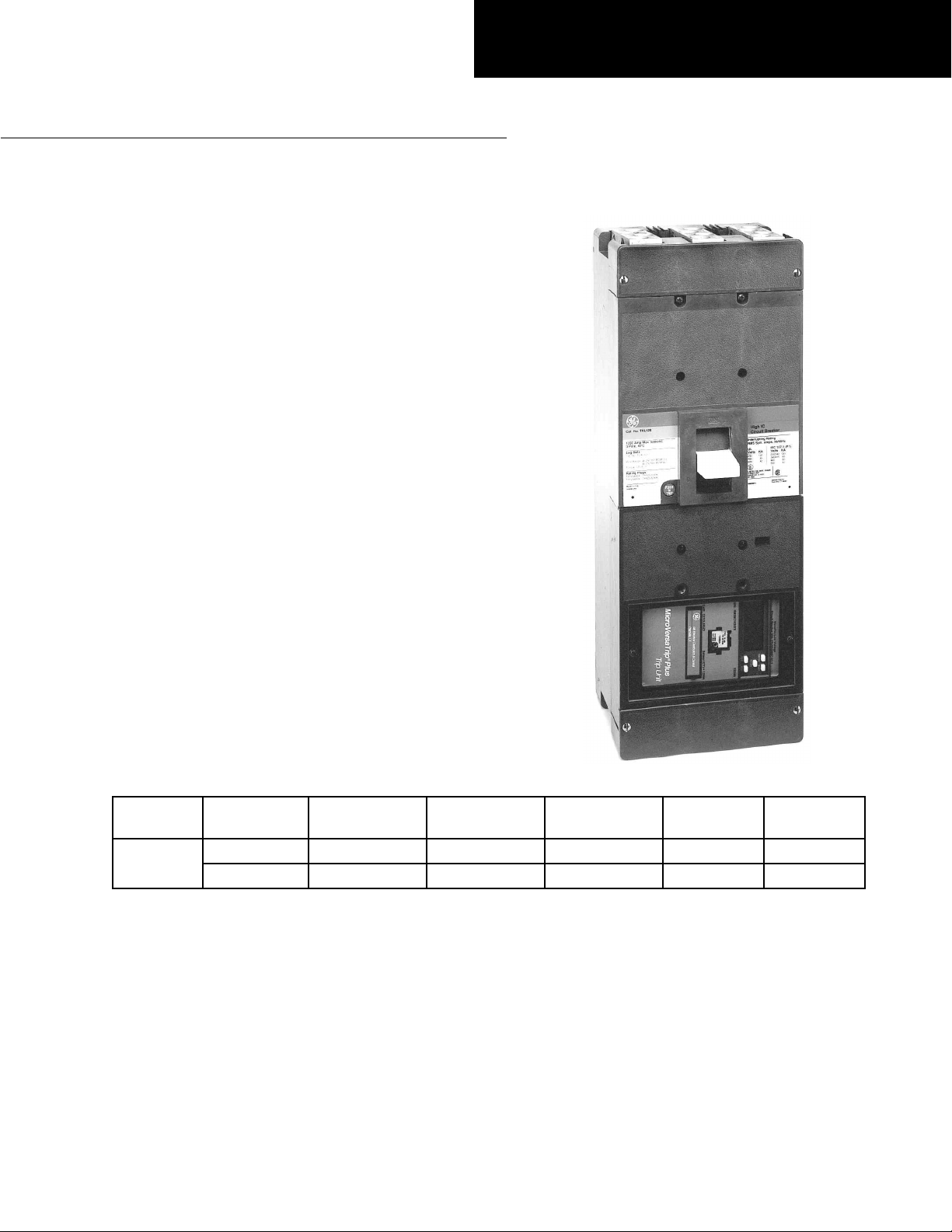
TKH8S, TKH12S, TKL8S, and TKL12S Breakers
Introduction
This publication contains information on mounting
dimensions, lugs and lug covers, internal and external
accessories, and trip unit and rating plug selection for K
Frame molded-case circuit breakers, as shown in Figure
1. It also describes the installation of neutral current
sensors for ground-fault protection.
Lug and Lug Cover Selection
Circuit breakers are provided without lugs and with end
covers (suitable for bus connections). The available lugs
and lug covers are listed in Table 1.
• Lug covers are used with lug connectors.
• End covers are used when connecting a bus to the
breaker.
• Wire ranges:
– TCAL81: (3) 3/0–500 MCM Cu/Al
– TCO81A: (3) 3/0–500 MCM Cu
– TCAL121: (4) 250–350 MCM Cu or
250–500 MCM Al
– TCO121: (4) 250–400 MCM Cu
Molded-Case Circuit Breakers
MicroVersaTrip Plus™ Trip Unit in
GEH–5374A
Frame
Type
1200
Sensor Rating
(Amps)
800 All available TCAL81 TCO81A 286A8066G3 286A8066G2
1200 All available TCAL121 TCO121 286A8066G1 286A8066G2
Rating Plug
(Amps)
Table 1. Catalog numbers of lugs, lug covers, and end covers.
Standard Lugs
Cu/Al Cat. No.
Optional Lugs
Cu Cat. No.
Lug Covers
Cat. No.
End Covers
Cat. No.
Page 2
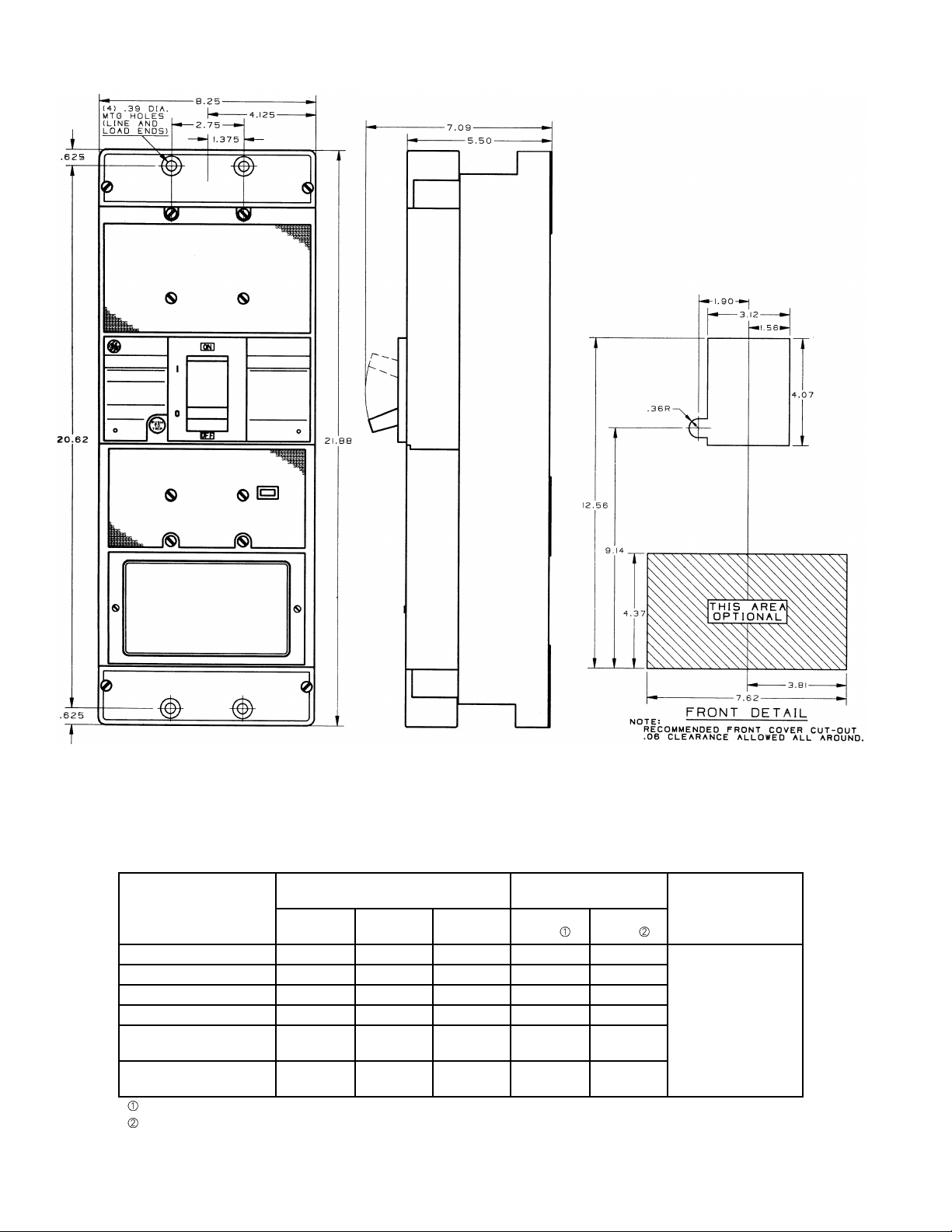
Outline Drawing for TKH8S, TKH12S, TKL8S, TKL12S
Internal Accessories
Internally mounted accessories are UL listed and field
installable, except for the bell alarm, which is only factory
installed. Available accessories are listed in Table 2.
Pole Mounting Lead Exit
Accessory Installation
Left Center Right Side Back
Auxiliary Switches X X X
Shunt Trip X X X
Bell Alarm Switch X X X Any One
Undervoltage Release X X X plus
Combination Shunt
Trip with Aux Sw
Combination Under–
voltage with Aux Sw
UL listed.
Not UL listed.
Table 2. Available internal accessories and mounting positions.
For detailed information on accessory applications, see
the GE BuyLog, GEP-1100, and GEP-746.
Total No. of
Accessories
Within Any One
Breaker
X X X
X X X
Bell Alarm
Page 3

External Accessories
C
2
12
LSI
G
Z1
R
• Motor-operated mechanisms
• Back-connected studs
• Plug-in and bolt-on bases for 100%-rated breakers
• Mechanical interlocks
• Padlocking devices
Trip Unit Selection
MicroVersaTrip Plus™ trip unit functions available in K
Frame breakers are listed in Table 3.
Code Description Function
C Power Break, J Frame, K Frame Breaker Type
2 2000 A maximum CT Breaker Frame
08 800 A
12 1200 A CT
L Long-time (standard) Overcurrent
S Short-time Protection
I Instantaneous
G Ground fault Ground Fault Protection
Z1 Ground-fault zone-selective interlock Optional
Z2 Ground fault and short-time ZSI Functions
R Replacement trip unit Replacement
For single-phase, 3-wire or 3-phase, 4-wire applications, order appropriate
neutral sensor.
Requires purchase of zone-selective interlock module(s) type T1M1 (120
Vac control voltage).
Table 3. Catalog number options for MicroVersaTrip Plus™ trip units available with K Frame circuit breakers.
• Handle operator
– TDA: flange mounted, variable depth
– TDM: door mounted, variable depth
– TDR: integral mechanism, fixed depth
For a complete listing of external accessories, see the GE
BuyLog, GEP-1100, and GEP-746.
For detailed information on trip unit selection, see GE
publication GEH-6273.
Installed
Rating Plug Selection
Rating plugs available with MicroVersaTrip Plus™ trip
units in K Frame breakers are listed in Table 4.
Frame Type Sensor Rating, A Current Rating, A Rating Plug Cat. No.
K800 800 500 TR8B500
K1200 1200 800 TR12B800K
Table 4. Rating plugs available with MicroVersaTrip Plus™ trip units in K Frame breakers.
Test Kit, Cat. No. TVRMS2
The portable, battery-powered test kit provides for
MicroVersaTrip Plus or PM trip unit self-tests and
functional trip/no-trip tests. It also provides for defeat of
the ground-fault function and can be used in conjunction
with high-current test equipment. Interface is via a plug
on the front of the trip unit and tests can be conducted
with the breaker in service. The kit can also be powered
by a 120 Vac source.
300 TR8B300
400 TR8B400
600 TR8B600
700 TR8B700
800 TR8B800
600 TR12B600K
1000 TR12B1000K
1200 TR12B1200K
Application Information
For information on derating, time-current curves,
inspection, and testing, refer to GE publication GET-
2779.
Page 4

Neutral Current Sensor
Connection
A neutral current sensor must be used for ground-fault
protection on all single-phase, three-wire systems and
three-phase, four-wire systems.
1. Remove the two screws that hold the lug cover in
place, then remove the lug cover.
2. Remove the four screws that hold the lower part of
the breaker cover in place.
3. Lift off the lower part of the breaker cover.
4. Attach the leads of the current sensor to the
terminations shown in the illustration. The vertical
surfaces of the terminals closest to the trip unit are
labeled BLACK and WHITE on the left and right sides
of the breaker, respectively. Maintain the proper
polarity by connecting the black wire to the black
connector and the white wire to the white connector.
Use #14 AWG (minimum) twisted-pair insulated
conductors.
Cover
Screws
Black
Terminal
5. File break-out locations in the bottom cover with a
circular file. Route the ground-fault leads out the
bottom cover, being careful not to pinch the leads.
6. Replace the breaker cover, then replace the lug
cover, attaching both with the fasteners removed in
steps 1 and 2. Tighten the screws to 14–20 in-lb.
White
Terminal
These instructions do not cover all details or variations in equipment nor do they provide for every possible contingency that
may be met in connection with installation, operation, or maintenance. Should further information be desired or should
particular problems arise that are not covered sufficiently for the purchaser’s purposes, the matter should be referred to the
GE Company.
g
GE Industrial Systems
General Electric Company
41 Woodford Ave., Plainville, CT 06062
GEH5374 R02 1000 © 2000 General Electric Company
 Loading...