

Page 1
Introduction
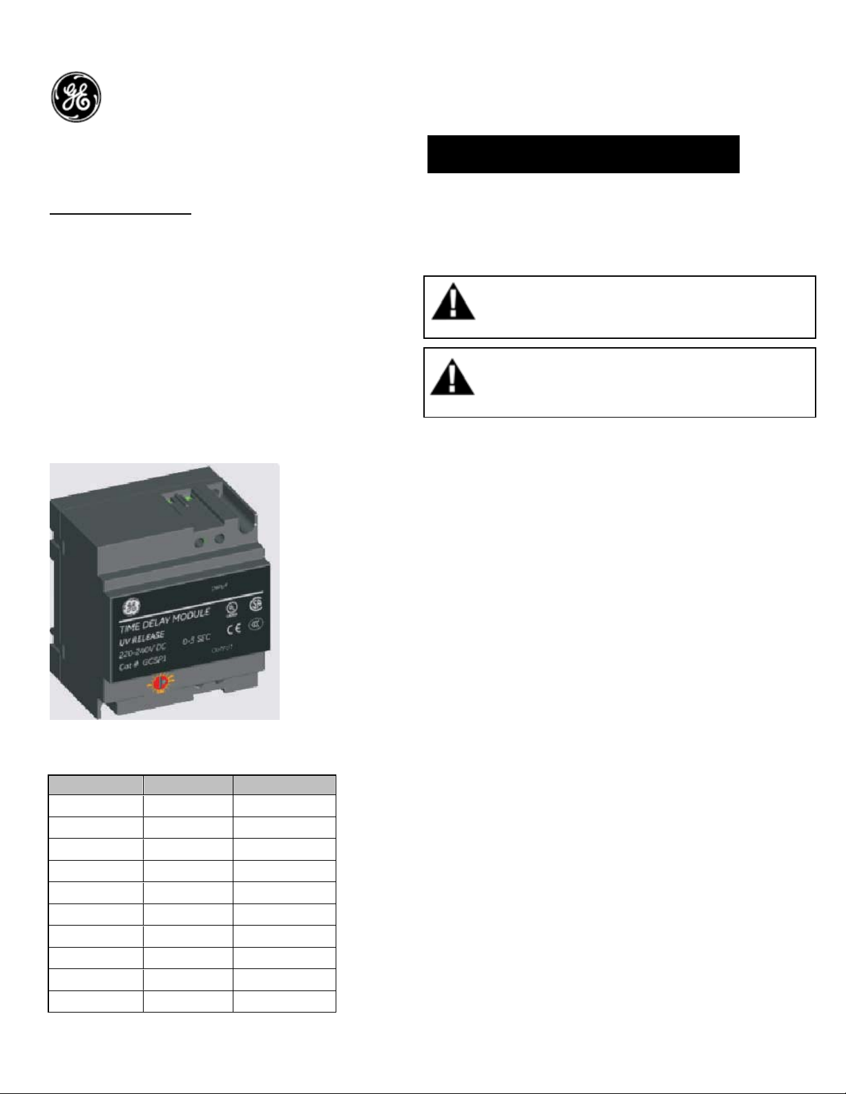
Time Delay Module:
The de-energizing operation of the undervoltage
release can be delayed. This optional, externally
mounted, module has an adjustable time delay of
one to three seconds. The device can be
implemented to prevent un-desired Breaker
‘tripping’ due to momentary voltage outages
(50% of rated Voltage) and is connected in series
with the under voltage release. The delay is in
addition to the Under Voltage Release delay of 50
msec. The breaker must have a UVR installed for
the External Time Delay Module to work.
Table 1. Catalog Numbers and Ratings
Catalog No DC Voltage AC Voltage
GTDM048D
GTDM048A
GTDM060D
GTDM120A
GTDM120D
GTDM208A
GTDM240A
GTDM240D
GTDM250D
GTDM277A
48VDC
48VAC
60VDC
120-130VAC
110-130VDC
208VAC
220-240VAC
220-240VDC
250VDC
250-277VAC
DEH-41406 Installation Instructions
EntelliGuard ® G Circuit Breaker
Accessories
Time Delay Module
WARNING: Before installing any accessories, turn the
breaker OFF, disconnect it from all voltage sources,
and discharge the closing spings.
AVERTISSEMENT: Avant d’installer tout accessoire,
mettre le disjoncteur en position OFF, le déconnecter
de toute tension d’alimentation , et décharger les
resorts d’armement
Refer to DEH-41410 for the Under Voltage
Release in the breaker
Use the following procedure to install the Time
Delay Module (TDM) accessory into the circuit
breaker.
1. Verify that the rating on the Time Delay Module
(TDM) identification plate matches the voltage
rating required for the application, as listed in
Table 1.
2. The time delay module has to be mounted
external to the breaker.
3. Switch off the breaker & equipment and ensure
the panel is isolated
4. TDM module can be mounted in two ways
either using two M4 screws on the panel or to a
din rail.
5. For assembling using the screw, drill and tap
two M4 holes at a distance as shown in the Fig. 1.
1
Page 2
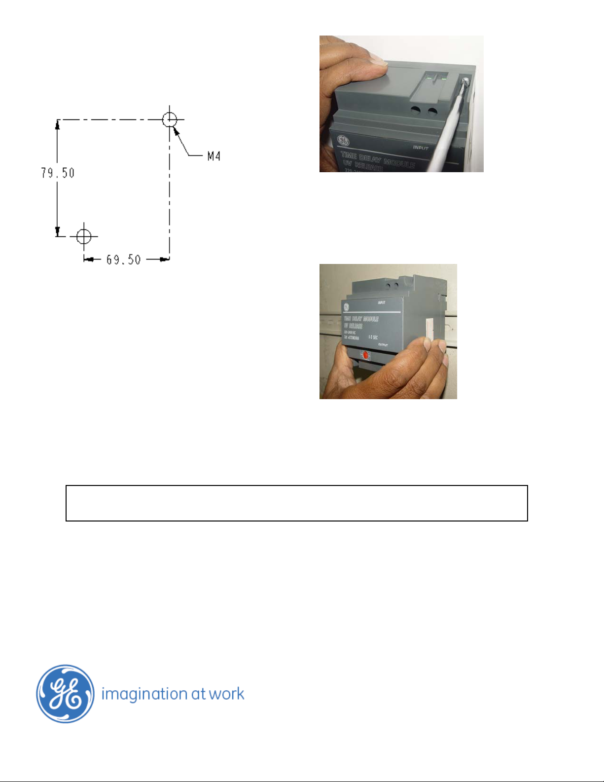
(3.13)
Fig 1: Mounting holes location
dimensions are in mm (Inches)
(2.74)
6. Assemble the TDM module with two M4 screws
as shown in the fig 2.
These instructions do not purport to cover all details or variations in equipment nor, to provide contingency to be met in connection
with installation, operation, or maintenance. Should further information be desired, or should particular problems arise which are not
covered sufficiently for the purchaser’s purposes, the matter should be referred to GE.
GE
41 Woodford Ave, Plainville, CT 06062
www.geelectrical.com
© 2009 General Electric Company
Figure 2. TDM mounting
7. Alternatively TDM can be mounted on a din rail
as shown in the fig 3.
Figure 3. Din rail mounting
-
2
 Loading...