

Page 1
g
p
g
quip
p
y
DEH042 Installation Instructions R03
Spectra Series™ Power Panelboards
Circuit Breaker Cover
WARNING: Danger of electrical shock or injury.
Turn
OFF
switchboard before workin
ment or removing any component. Do
e
not remove circuit
ower ahead of the panelboard or
inside the
rotective devices or an
other component until the power is turned
OFF.
General
These instructions apply to the following circuit breaker
frames: SE, SF, TE, TF, TQ, and TEL.
Installation
1. Select the breaker cover supports and breaker covers.
Table 1 lists the catalog numbers of the appropriate
cover supports for various switchboard and
panelboard sizes. Table 2 lists the breaker covers for
various breaker types.
Switchboard or Panelboard Width
Cover Height
41/8" (3X) &
1
5
/2" (4X)
23/4" (2X) 208C1850P6 208C1850P5 208C1850P5
• Use 208C1850P3 for SFHA, SFLA, SFPA, TFL, TFJ, TFK, and
THFK, in single-branch mountings.
27 & 31" Pnlbd
35" Swbd
208C1850P4* 208C1850P3 208C1850P3
Table 1. Circuit breaker cover support catalog numbers for various
panelboard and switchboard widths.
Switchboard or Panelboard Width
Cover Height
SEDA, SEHA, SELA, SEPA – Double-branch mount only
41/8" (3X) 208C4262G32 208C4262G33 208C4262G34
51/2" (4X) N/A 208C4262G35 208C4262G36
SFHA, SFLA, SFPA – Single-branch mount (see Figure 1)
41/8" (3X) 208C4262G53 208C4262G54 208C4262G55
51/2" (4X) N/A 208C4262G56 208C4262G57
41/8" (3X) 208C4262G58 208C4262G59 208C4262G60
51/2" (4X) N/A 208C4262G61 208C4262G62
23/4" (2X) 208C4262G26 208C4262G27 208C4262G28
41/8" (3X) 208C4262G29 208C4262G30 208C4262G31
TFJ, TFK, THFK, TFL – Single-branch mount (see Figure 1)
41/8" (3X) 208C4262G1 208C4262G2 208C4262G3
41/8" (3X) N/A 208C4262G6 208C4262G7
23/4" (2X) 208C4262G20 208C4262G21 208C4262G22
41/8" (3X) 208C4262G23 208C4262G24 208C4262G25
27 & 31" Pnlbd
35" Swbd
SFHA, SFLA, SFPA – Double-branch mount
TEB, TED, THED, TEL – Double-branch mount
TFJ, TFK, THFK, TFL – Double-branch mount
TQD, THQD – Double-branch mount
Table 2. Circuit breaker cover catalog numbers for various
panelboard and switchboard widths.
36 & 40" Pnlbd
40" Swbd
36 & 40" Pnlbd
40" Swbd
44" Pnlbd
45" Swbd
44" Pnlbd
45" Swbd
2. Mount the circuit breaker cover supports. Mount the
breaker cover supports supplied in the kit to the
circuit breaker module or mounting plate, according
to the instructions supplied with the module or
mounting plate.
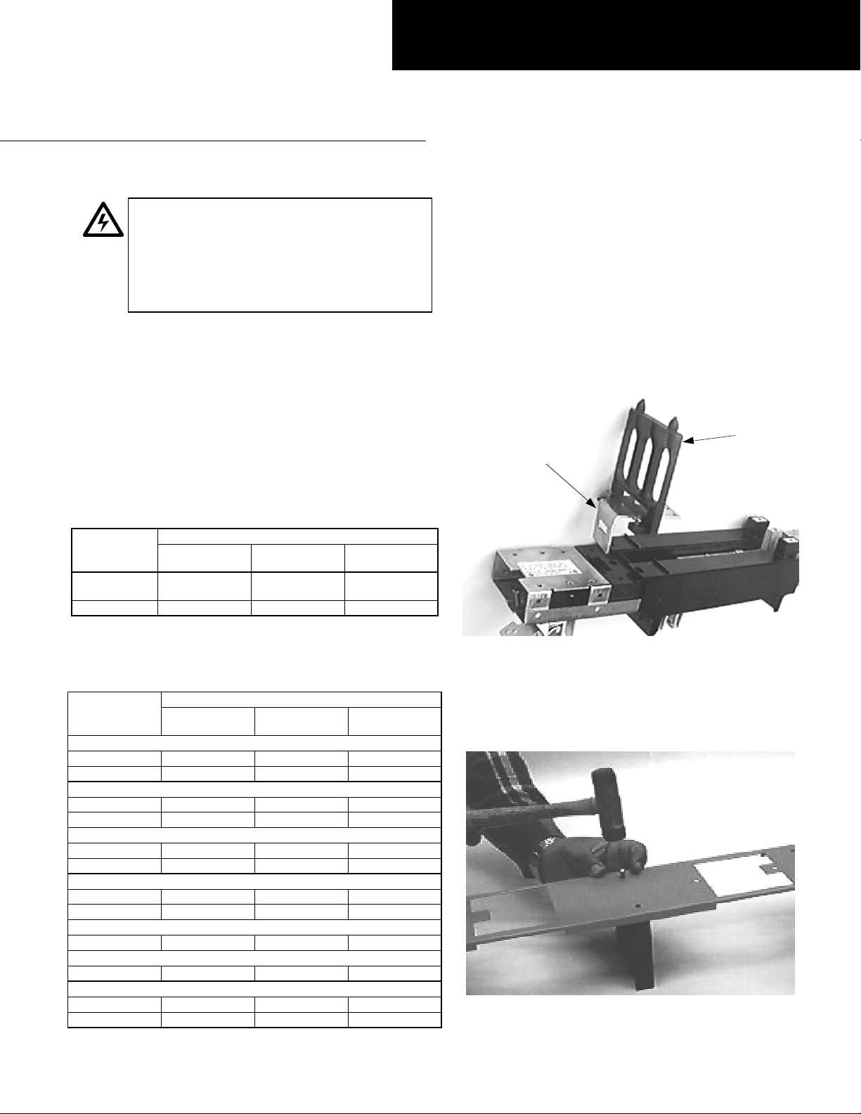
To install the cover support for single-branch SF and
TF breakers, first remove the breaker mounting
bracket by prying back the plastic spring clip on the
module. Slide the cover support on and snap the
breaker mounting bracket back into the module.
Fasten the cover support to the module, as shown in
Figure 1.
Breaker
Mounting
Bracket
Cover
Support
Figure 1. Installing the cover support for single-branch SF and TF
breakers.
3. Attach the center barrier to the breaker cover for
double-branch 3X or 4X TEB, TED, THED, TQD,
THQD, SE, SF, TFK, THFK, and TFL breakers. Use
two push-in rivets, as shown in Figure 2.
Figure 2. Attaching the center barrier to the breaker cover.
Page 2
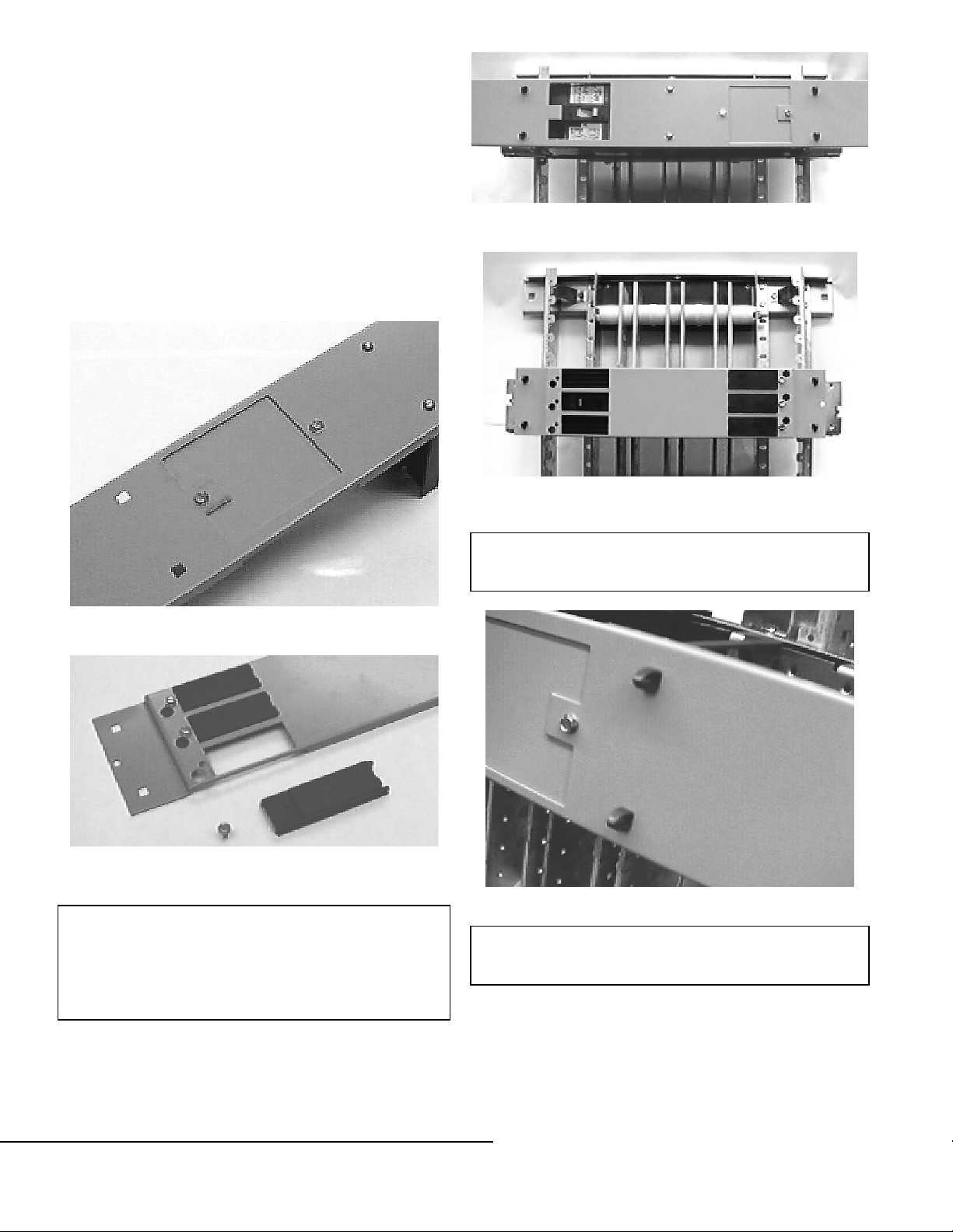
4. Install the space fillers to any holes in the filler plate
quip
y
p
p
g
with no breakers mounted behind.
For SE, SF, TFJ, TFK, THFK, and TFL breakers, use
3
the steel space filler and two #10 x
/8" screws,
tightened to 25 in-lb, as shown in Figure 3.
For TEB, TED, THED, TQD, THQD, and TEL
breakers, use the plastic space fillers. Install the filler
from the underside of the breaker cover. Engage the
slotted end of the space filler with the inside edge of
the opening in the breaker cover. Secure the other
end in place with a #10 x
7
/8" screw, tightened to 15
in-lb, as shown in Figure 4.
5. Install the assembled breaker cover over the flexible
prongs on the filler supports, as shown in Figures 5
and 6.
Figure 5. Breaker cover installed on the filler supports for SE, SF, TFJ,
TFK, THFK, and TFL breakers.
Figure 6. Breaker cover installed on the filler supports for TEB, TED,
THED, TQD, THQD, and TEL breakers.
Figure 3. Installing the steel space filler for SE, SF, TFJ, TFK, THFK,
and TFL breakers.
Figure 4. Installing the plastic space fillers for TEB, TED, THED, TQD,
THQD, and TEL breakers.
These instructions do not cover all details or variations in
e
ment nor do they provide for every possible contingency that
ma
be met in connection with installation, operation, or
maintenance. Should further information be desired or should
articular problems arise that are not covered sufficiently for the
urchaser’s purposes, the matter should be referred to the GE
Company.
CAUTION: To ensure secure mounting, push the breaker
cover completely over the four flexible prongs on top of
the filler supports, as shown in Figure 7.
Figure 7. Breaker cover securely mounted on the flexible prongs.
NOTE: Push-on breaker covers may bend if not removed
properly. Pull the upper edge of the breaker cover off the
flexible prongs, then pull the lower edge free.
GE Industrial Systems
General Electric Company
41 Woodford Ave., Plainville, CT 06062
DEH042 R03 0801 © 2001 General Electric Company
 Loading...