

Page 1
GEK–105263B Instructions
g
______________________________________________________
for Power/Vac Vacuum Circuit Breakers
Test Cabinet
Page 2

Page 3

Power/Vac
Table of Contents
Section 1. Introduction
1-1 Safety................................................................................................................................................ 3
1-2 Maintenance ..................................................................................................................................... 3
Section 2. Receiving, Handling & Storage
2-1 Receiving.......................................................................................................................................... 4
2-2 Handling.......................................................................................................................................... 4
2-3 Storage ............................................................................................................................................. 4
Section 3. Description & Principals of Operation
Section 4. Installation
Section 5. Maintenance
...................................................................................... 4
............................................................................................................................................. 6
......................................................................................................................................... 7
Test Cabinet
1
Page 4

Power/Vac
Test Cabinet __________________________________________________
List of Figures
1. Typical Test Cabinet ........................................................................................................................................ 5
2. Test Cabinet Outline........................................................................................................................................ 6
3. Wiring Diagram for Test Cabinet with 1-Trip Coil.......................................................................................... 7
4. Wiring Diagram for Test Cabinet with 2-Trip Coils ........................................................................................ 8
5. Wiring Diagram for Test Cabinet with 1-Trip Coil and 1-UVTD.................................................................... 9
THESE INSTRUCTIONS ARE INTENDED FOR USE BY QUALIFIED PERSONNEL FOR INSTRUCTION AND MAINTENANCE PURPOSES.
REPRODUCTION IN WHOLE OR IN PART IS NOT PERMITTED WITHOUT THE EXPRESS PERMISSION OF GENERAL ELECTRIC.
2
Page 5

Power/Vac
Test Cabinet
Section 1. Introduction
1-1 Introduction
This manual provides the information needed by the user to
properly install, operate and maintain the Test Cabinet.
1-2 Safety
Each user must maintain a safety program for the protection of
personnel, as well as other equipment, from the potential hazards
associated with electrical equipment.
The following requirements are intended to augment the user’s
safety program, but NOT supplant the user’s responsibility for
devising a complete safety program. The following basic industry
practiced safety requirements are applicable to all major electrical
equipment such as switchgear or switchboards. GE neither
condones nor assumes any responsibility for practices which
deviate from the following:
1. ALL CONDUCTORS MUST BE ASSUMED TO BE
ENERGIZED UNLESS THEIR POTENTIAL HAS BEEN
MEASURED AS GROUND AND SUITABLE GROUNDING
CONDUCTORS HAVE BEEN APPLIED TO PREVENT
ENERGIZING. Many accidents have been caused by back
feeds from a wide variety of sources.
2. Although interlocks to reduce some of the risks are
provided, the individual’s actions while performing service
or maintenance are essential to prevent accidents. Each
person’s knowledge; his mental awareness; and his planned
and executed actions often determine if an accident will
occur. The most important method of avoiding accidents is
for all associated personnel to carefully apply a thorough
under-standing of the specific equipment from the
viewpoints of its purpose, its construction, its operation and
the situations which could be hazardous.
All personnel associated with installation, operation and
maintenance of electrical equipment, such as power circuit
breakers and other power handling equipment, must be
thoroughly instructed, with periodic retraining, regarding power
equipment in general as well as the particular model of
equipment with which they are working. Instruction books, actual
devices and appropriate safety and maintenance practices such as
OSHA publications, National Electric Safety Code (ANSI C2), the
National Electric Code, and National Fire Protection Association
(NFPA) 70B Electrical Equipment Maintenance must be closely
studied and followed. During actual work, supervision should
audit practices to assure conformance.
1-3 Maintenance
Excellent maintenance is essential for reliability and safety
of any electrical equipment. Maintenance programs must
be tuned to the specific application, well planned and carried out
consistent with both industry experience and manufacturer’s
recommendations. Local environment must always be considered
in such programs, including such variables as ambient
temperatures, extreme moisture, number of operations, corrosive
atmosphere or major insect problems and any other unusual or
abusive condition of the application.
One of the critical service activities, sometimes neglected, involves
the calibration of various control devices. These monitor
conditions in the primary and secondary circuits, sometimes
initiating emergency corrective action such as opening or closing
circuit breakers. In view of the vital role of these devices, it is
important that a periodic test program be followed. As was
outlined above, it is recognized that the interval between periodic
checks will vary depending upon environment, the type of device
and the user’s experience. It is the GE recommendation that,
until the user has accumulated enough experience to select a test
interval better suited to his individual requirements, all significant
calibrations be checked at an interval of one to two years.
To accomplish this, some devices can be adequately tested using
test sets. Specific calibration instructions on particular devices
typically are provided by supplied instruction books.
Instruction books supplied by manufacturers address components
that would normally require service or maintenance during the
useful life of the equipment. However, they can not include every
possible part that could require attention, particularly over a very
long service period or under adverse environments. Maintenance
personnel must be alert to deterioration of any part of the
supplied switchgear, taking actions, as necessary to restore it to
serviceable status.
Industry publications of recommended maintenance practices
such as ANSI/NFPA 70B, Electrical Equipment Maintenance,
should be carefully studied and applied in each user’s formation
of planned maintenance.
Some users may require additional assistance from GE in the
planning and performance of maintenance. GE can be contracted
to either undertake maintenance or to provide technical
assistance such as the latest publications.
The performance and safety of all equipment may be
compromised by the modification of supplied parts or their
replacement by non-identical substitutes. All such design changes
must be qualified to ANSI/IEEE Standard C37.59.
The user should methodically keep written maintenance records
as an aid in future service planning and equipment reliability
improvement. Unusual experiences should be promptly
communicated to GE.
3
Page 6

Power/Vac
Section 2. Receiving, Handling and Storage
2-1. Receiving
Each test cabinet is carefully inspected before shipment.
Immediately upon receipt of the test cabinet, an
examination should be made for any damage sustained
in transit. If injury or rough handling is evident, a
damage claim should be filed immediately with the
transportation company and the nearest General Electric
Sales Office should be notified.
It is expected that due care will be exercised during the
unpacking and installation of the test cabinet so that no
damage will occur from careless or rough handling, or
from exposure to moisture or dirt.
2-2. Handling
Normal care in handling the test cabinet will result in a
trouble-free installation and long testing life.
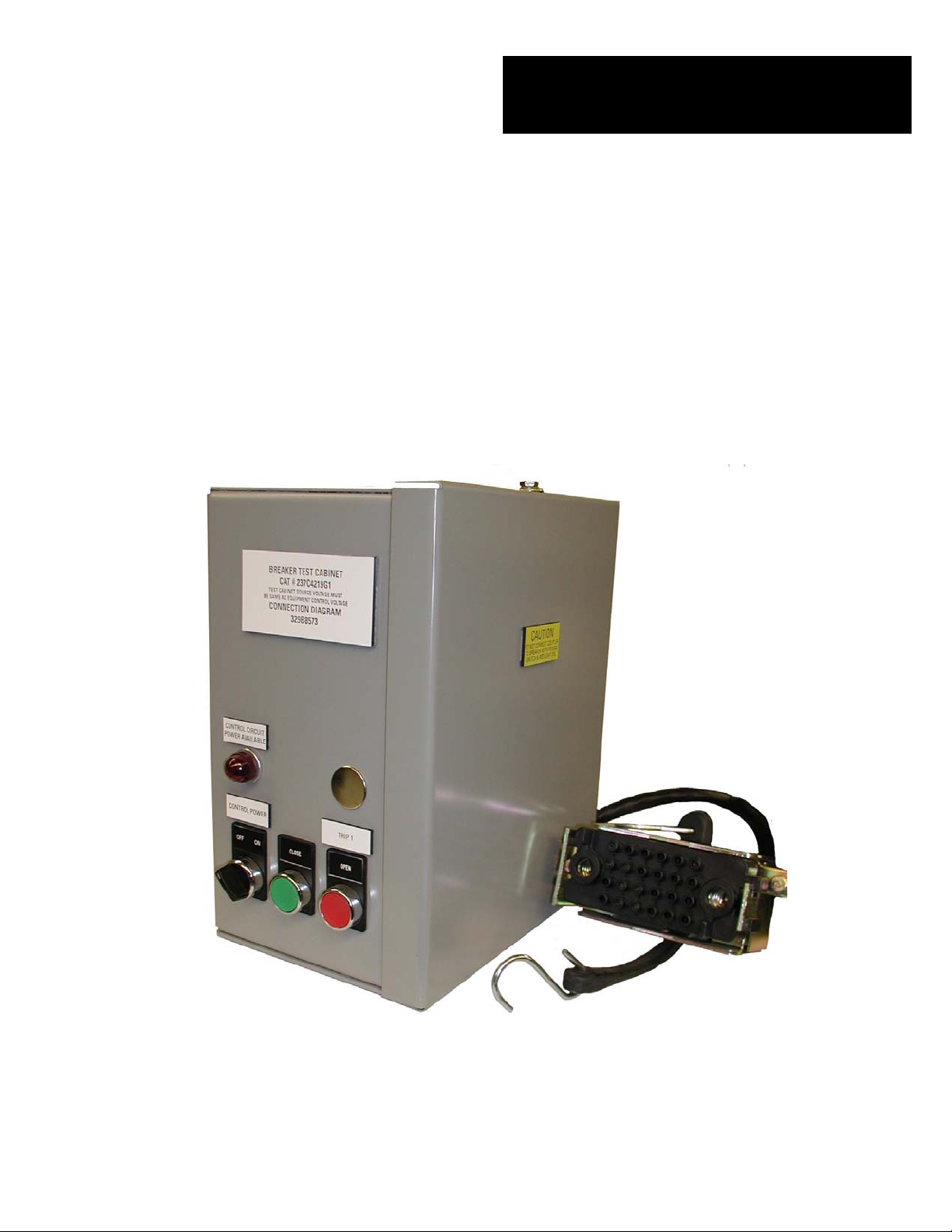
Section 3. Description and Principles of Operation
The test cabinet, catalog no. 0231C9827G001, G002, G003
(Fig. 1) is used to operate a Power/Vac circuit breaker that
has been removed from the metal-clad equipment. It
provides a convenient means of accessing the electrical
close and trip circuits of the breaker during maintenance
and inspection procedures.
This unit is designed to be wall or cabinet mounted. It has
an 8-foot cable (1), a storage bracket (2), control power
selector switch (4), close push-button switch (5) for closing
the breaker, trip 1 push-button switch(6) for opening the
breaker. An optional pushbtton switch is available for
testing circuit breakers that have either a 2
direct-acting undervoltage trip device.
Test Cabinet
2-3. Storage
It is recommended that the test cabinet be put
immediately in its permanent location. If this is not
possible, the following precautions should be taken to
assure proper storage of the test cabinet.
1. The test cabinet should be stored in a clean
location, free from corrosive gases or fumes;
particular care, for example, should be taken to
protect the equipment from moisture and dust, as
this combination has a very corrosive effect on many
parts.
2. If the test cabinet is stored for any length of time, it
should be inspected periodically to see that rusting
has not started and to insure good mechanical
condition. Should the cabinet be stored under
unfavorable atmospheric conditions, it should be
cleaned and dried out before being placed in
service.
An indicating light (8), connected to the close circuit fuse
block, indicates the selector switch (4) is on or off. The
indicating light is furnished from the factory with a 250V
resistor. If the close circuit voltage is 125V or less, replace
the indicating light resistor with the resistor taped to the
inside of the cabinet (9).
Inside the unit is a rectifier board (10), a stud for
attaching a ground wire (14) and fuse blocks (11,12,13)
for supply voltage fuses. There are also two holes, one on
upper left and the other on lower right to accommodate
nd
trip coil or a
3/8 inch studs for mounting.
CAUTION: It is strongly recommended that the test
coupler be connected to the breaker before the power is
turned on.
4
Page 7

9
11 12 13
14
8
7
6
4 5
Fig. 1 Typical Test Cabinet
1- CABLE
2- STORAGE BRACKET
3- TEST COUPLER
4- CONTROL POWER SELECTOR SWITCH
5- CLOSE PUSHBUTTON
6- TRIP COIL #1 PUSHBUTTON
7- TRIP COIL #2 OR UVTD PUSHBUTTON
8- INDICATING LIGHT (w/ 250V resistor)
9- 125V INDICATING LIGHT RESISTOR
10- RECTIFIER BOARD
11- MOTOR CIRCUIT FUSE BLOCK
12- CLOSE CIRCUIT FUSE BLOCK
13- TRIP CIRCUIT FUSE BLOCK
14- GROUND STUD
10
3
2
5
Page 8

Power/Vac
Section 4. Installation
The test cabinet should be installed on the wall at a
location where maintenance and testing of the breaker
can be conveniently done.
Make sure that the green ground conductor is connected
to electrical ground.
Section 5. Maintenance
The contact surfaces of the coupler require periodic
lubrication to inhibit oxidation and minimize friction. It
is recommended that during each maintenance interval,
the pins of the breaker coupler be lightly coated with
0282A2048P009 grease.
Conduits may be installed for cables to supply control
power for testing. Two 1-inch diameter grommets are
located on top accomodate wiring. Refer to the wiring
diagrams figures 2, 3, and 4 for control power
connections.
Aside from keeping the unit clean and dry, the most
important thing is to return the clamp to the cabinet area
when not connected to a breaker.
Test Cabinet
Fig. 2. Test Cabinet Outline Drawing
6
Page 9

Power/Vac
Section 5. Maintenance
Test Cabinet
Fig. 3. Test Cabinet Wiring Diagram for 1-Trip Coil
7
Page 10

Fig. 4. Test Cabinet Wiring Diagram for 2-Trip C
8
Page 11

Fig. 5. Test Cabinet Wiring Diagram for 1-Trip Coil & UVTD
9
Page 12

These instructions do not purport to cover all details or variations in equipment nor to provide for every possible
contingency to be met in connection with installation, operation or maintenance. Should further information be desired or
should particular problems arise which are not covered sufficiently for the purchaser’s purposes, the matter should be
referred to the General Electric Company.
g
______________________________________________________
General Electric Company
510 East Agency Road
West Burlington, Iowa 52655
GEK-105263B 1999 General Electric Company
GE Industrial Systems
 Loading...