

Page 1
GE Energy
Industrial Solutions
GEH-6254 Installation Instructions
Voltage Conditioner Assembly
For Spectra® RMS Molded-Case Circuit Breakers
TM
with microEntelliGuard
, MicroVersaTrip® PM or MicroVersaTrip® Plus Trip Units
For Catalog Number SVCAA
Circuit Breaker Accessory
Overview
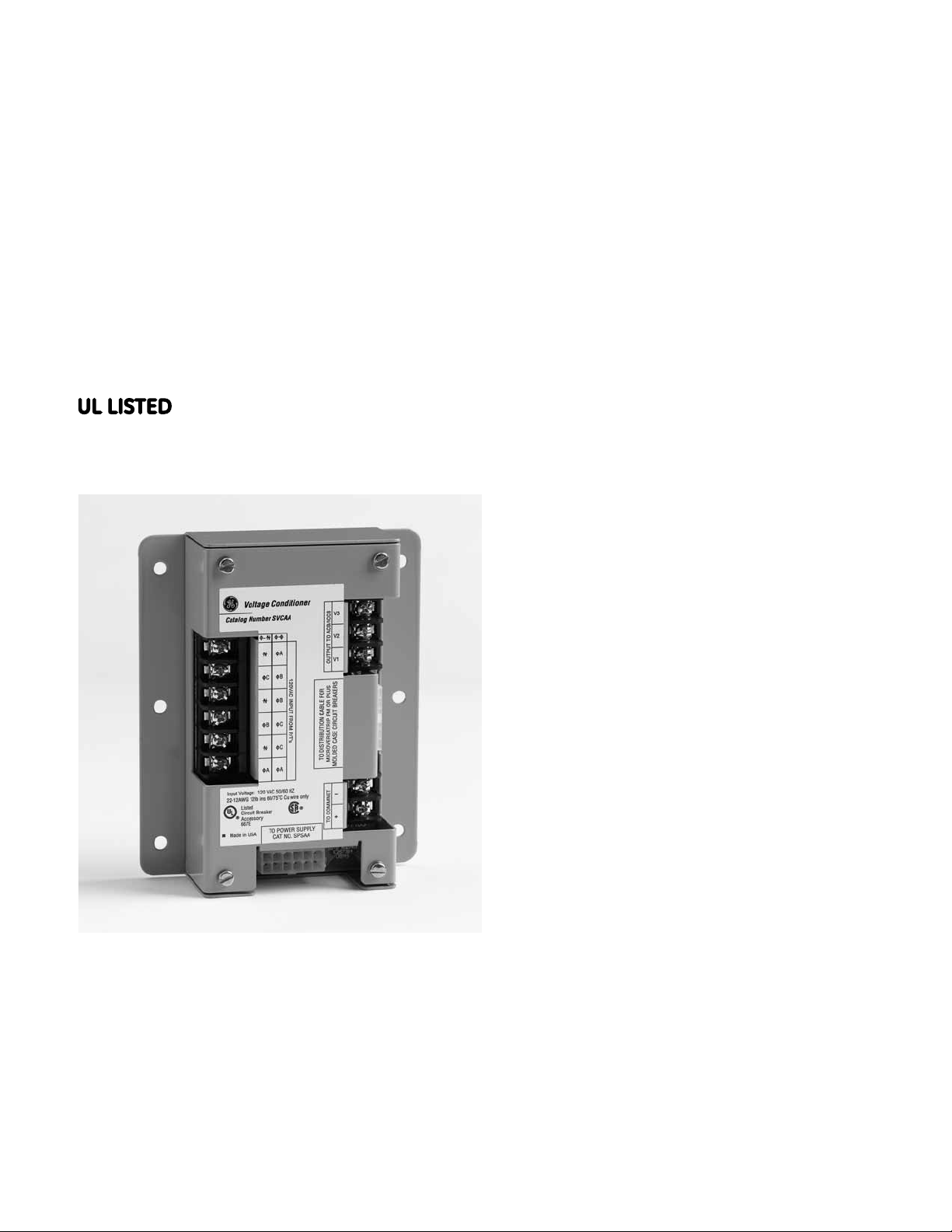
The General Electric Voltage Conditioner Assembly
is used to provide voltage-sensing signals to
Spectra
microEntelliGuard
Units via the Distribution Cable System.
The assembly has the maximum capacity to provide
voltage signals to a Distribution Cable System
consisting of 20 Spectra
Breakers with microEntelliGuard
PM/Plus Trip Units with a maximum system cable
length of 40 feet.
®
RMS Molded-Case Circuit Breakers with
TM
or MicroVersaTrip® PM/Plus Trip
®
RMS Molded-Case Circuit
TM
or MicroVersaTrip®
The Voltage Conditioner Assembly requires a power
supply source voltage of +24Vdc to operate properly.
The Power Supply Assembly (catalog number SPSAA)
or Power Supply Plate (catalog number SPSAI20,
SPSA208, SPSA240, SPSA480 or SPSA600) can provide
this required input. The unit also requires 120Vac @60
Hz voltage inputs from the secondary of three 1-VA
high accuracy potential transformers (not included).
The primary side of each potential transformer must
be fused with 2-amp class CC fuses (not included). The
Voltage Conditioner Assembly is designed to operate in
temperatures between 0°C and 70°C.
Page 2
GEH-6254 Installation Instructions
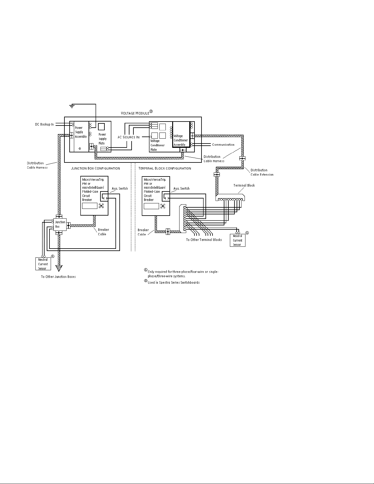
Figure 1 shows how the Voltage Conditioner Assembly is used in a typical MicroVersaTrip® PM system.
®
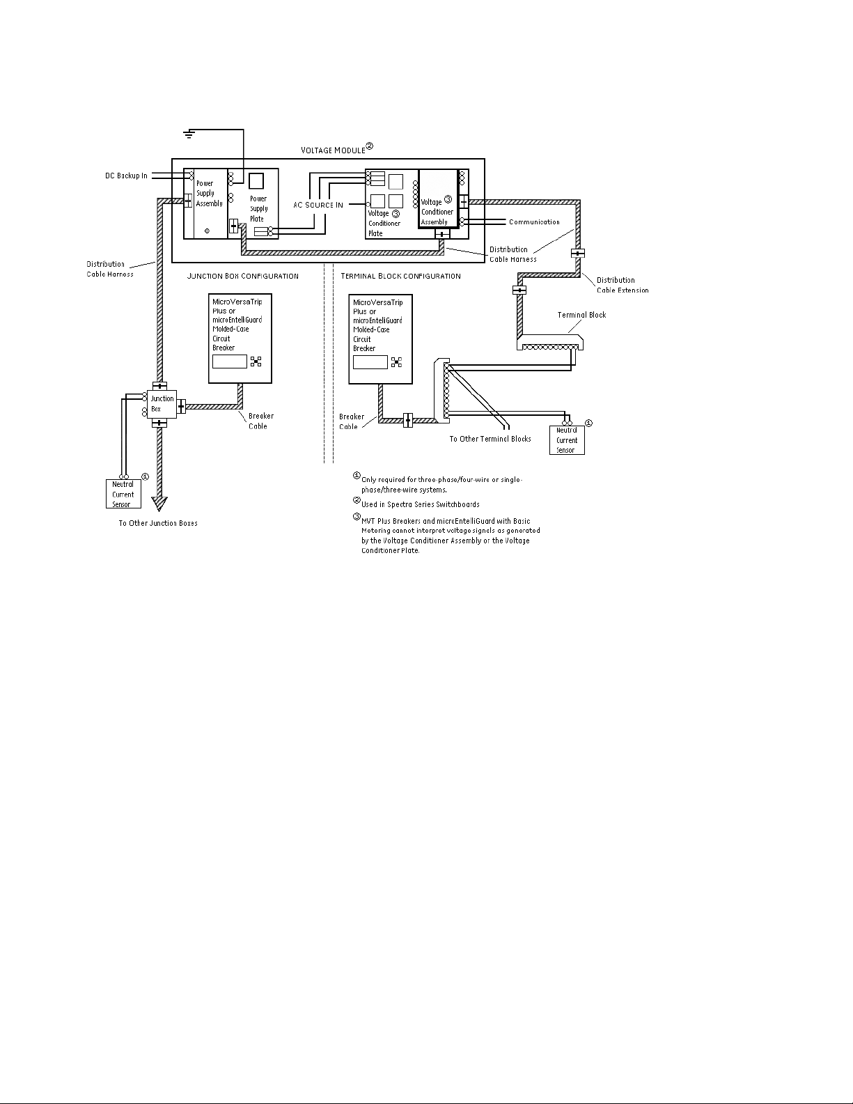
Figure 2 shows how the Voltage Conditioner Assembly is used in a typical MicroVersaTrip
TM
microEntelliGuard
diagram shown in Figure 2 applies to microEntelliGuard
Trip Unit can be used with either configuration, i.e. Figure 1 or Figure 2. The connection
TM
Trip Units with Basic Metering.
Plus system. The
Figure 1. Typical MicroVersaTrip® PM Trip Unit System detailing the Voltage Conditioner Assembly.
Page 3
GEH-6254 Installation Instructions
Figure 2. Typical MicroVersaTrip® Plus Trip Unit System detailing the Voltage Conditioner Assembly.
Page 4

GEH-6254 Installation Instructions
A communications connection is provided for
applications where data is transmitted to an external
intelligent device (See Table 1). The distribution cable
system is used to interconnect the voltage signal on the
®
Voltage Conditioner Assembly and the Spectra
RMS
Molded-Case Circuit Breakers.
Table 1. Associated Software and Protocol for the different
Spectra
®
Series Breakers.
Trip Unit Type Protocol Software
MicroVersaTrip
microEntelliGuard
®
PM Commnet GE POWER LEADER
TM
Modbus EnerVista Viewpoint
TM
An additional voltage output connection is available for
applications where a voltage signal is needed on an Air
Circuit Breaker or Insulated Case Circuit Breaker with an
®
EntelliGuard™ TU or a MicroVersaTrip
not connect this voltage signal to a Spectra
PM Trip Unit (Do
®
Trip Unit.
The voltage signal structure is different between the
MCCB and ACB/ICCB Trip Unit platforms).
NOTE: THE VOLTAGE CONDITIONER ASSEMBLY IS SIZED
FOR A MAXIMUM OF 20 BREAKERS. Use of the Voltage
Conditioner Assembly to provide voltage sensing
signals and/or +24Vdc control power to a main Air
Circuit Breaker or a main Insulated Case Breaker with a
®
MicroVersaTrip
reduces the total quantity of 20 Spectra
Case Circuit Breakers with microEntelliGuard
MicroVersaTrip
PM/Plus or EntelliGuardTM TU Trip Unit
®
RMS Molded-
TM
®
PM/Plus Trip Units by one. The overall
or
maximum cabling length of the system remains 40 feet.
The Voltage Conditioner Assembly contains five
connection points. The following list contains a
description and type of connection points.
• “To Distribution Cable”
– 12-pin plug connector that mates with the 12-pin
receptacle of a Distribution Cable Harness (catalog
number SDCHA11, SDCHA30 or SDCHA60).
• “To Power Supply”
– 12-pin plug connector that mates with the 12-
pin receptacle of the Distribution Cable Harness
(catalog number SDCHA11, SDCHA30 or SDCHA60).
The other end of the harness MUST mate to either
a Power Supply Assembly (catalog number SPSAA)
or a Power Supply Plate (catalog number SPSA120,
SPSA208, SPSA240, SPSA480 OR SPSA600). Failure to
do so will result in the absence of a voltage-sensing
signal and inaccuracies in voltage dependent
®
informtaion / metering at Spectra
Case Circuit Breakers with MicroVersaTrip
Units and/or MicroVersaTrip
®
RMS Molded-
®
PM Trip
PM Programmers in Air
Circuit Breakers or Insulated Case Circuit Breakers.
• “120Vac Input From P/T’s”
– Six-screw terminal block for connection of the
potential transformers.
• “Communications”
– Two-screw terminal block for connection to
communications network.
• “Output to ACB/ICCB”
– Three-screw terminal block for optional voltage-
®
sensing signal output to MicroVersaTrip
PM or
EntelliGuard™ TU Trip Units in Air Circuit Breakers
and/or Insulated Case Circuit Breakers.
By plugging the Voltage Conditioner Plate into the
Distribution Cable System you create system wide
signals that are available to all breakers connected to
the system; a list of those functions appears in Table 2.
Table 2. Signals available on the Distribution Cable System by
connection of the Voltage Conditioner Assembly.
Spectra® RMS
Breaker with
microEntelliGuard
Trip Unit
control power
(+24vdc)
control power
(common)
system communication
(comm. +)
system communication
(comm. -)
voltage 1 (defined as
potential between Af &
N or between Af & Cf)
voltage 2 (defined as
potential between Bf &
N or between Cf & Bf)
voltage 3 (defined as
potential between Cf &
N or between Bf & Af)
Spectra
Breaker with
TM
MicroVersaTrip
Trip Unit
control power
(+24vdc)
control power
(common)
system communication
(comm. +)
system communication
(comm. -)
voltage 1 (defined as
potential between Af &
N or between Af & Cf)
voltage 2 (defined as
potential between Bf &
N or between Cf & Bf)
voltage 3 (defined as
potential between Cf &
N or between Bf & Af)
®
RMS
®
PM
®
Spectra
Breaker with
MicroVersaTrip
Plus Trip Unit
control power
(+24vdc)
control power
(common)
RMS
®
Page 5

GEH-6254 Installation Instructions
Dimensions and Wiring Diagrams
A Voltage Conditioner Assembly dimensioned drawing is provided in Figure 3 to assist in mounting the accessory.
The maximum unit weight is one and a half pounds.
Figure 3. Dimensioned drawing of the Voltage Conditioner Assembly (dimensions shown in inches).
Page 6

GEH-6254 Installation Instructions
Figure 4 contains a point-to-point wiring diagram for a Voltage Conditioner Assembly as it integrates into a typical
microEntelliGuardTM or MicroVersaTrip® PM system.
Figure 4. Wiring connections to the Voltage Conditioner Assembly for a typical MicroVersaTrip® PM System.
Page 7

GEH-6254 Installation Instructions
Connections
The screw terminals on the Voltage Conditioner
Assembly are labeled by function for clarity. The
terminal strip pocket will accommodate a spade
lug or ring terminal with a tongue width up to 0.320
inches. The terminal screw size is 10-32. To make the
Connection, attach an appropriate spade lug or ring
terminal to the wire, then slip the fastener beneath the
terminal screw and tighten.
The Voltage Conditioner Assembly also contains two
12-pin plug connectors. The connectors are keyed so
they cannot be inserted incorrectly into a mating 12pin receptacle connector. To connect to the Voltage
Conditioner Assembly plug(s), align the receptacle
interlock connector of a Distribution Cable Harness with
the plug hook connector of the Voltage Conditioner
Assembly. Insert the receptacle until the interlock and
hook catch (see Figure 5).
To disconnect from the Voltage Conditioner Assembly,
press down at the rear of the receptacle interlock until
the interlock clears the plug hook and withdraw the
receptacle interlock (see Figure 6).
PARTS AND OPTIONS
There are no user-serviceable components or parts
within the Voltage Conditioner Assembly; however, in
order for the unit to be properly protected, the fuses
and fuse holders listed in Table 3 are recommended for
use with the Voltage Conditioner Assembly (connect to
the primary side of the three potential transformers).
Table 4 contains a list of potential transformers that
are recommended for use with the Voltage Conditioner
Assembly (all units rated 120Vac on the secondary
and are rated 1-VA @ 60Hz with 0.2% on magnitude
accuracy). These potential transformers must always
be protected. It is recommended that the primary side
of the potential transformer be fused with the fuses
previously described.
If it is preferred to purchase a voltage-sensing
accessory that has factory-mounted AC line fuses and
three 1-VA @ 60Hz accuracy potential transformers,
Table 5 contains a listing of GE Voltage Conditioner
Plates. These Voltage Conditioner Plates contain the
Voltage Conditioner Assembly as an integral part
of the plate and are factory-wired from the Voltage
Conditioner Assembly to the three 1-VA potential
transformers and to the fuses holders (one set of fuses
is included).
Table 3. Recommended replacement fuses for use with the Power
Supply Assembly.
Class CC Current limiting Fuse Fuse Holder
Gould-Shawmut ATMR 2 Gould-Shawmut 3012R & DFC3M
Figure 5. Slide view of receptacle-plug insertion into
the Voltage Conditioner Assembly.
Figure 6. Side view of receptacle-plug removal from
the Voltage Conditioner Assembly.
Table 4. Recommended potential transformers for use with the
Voltage Conditioner Assembly.
Primary Rating Transfab Inc. Catalog Number
120Vac DL7027EE
208Vac DL7026FE
240Vac DL7029GE
277Vac DL7030LE
480Vac DL7025OE
600Vac DL7028QE
Table 5. Available Voltage Conditioner Plates.
Catalog Number Source Voltage Rating Comments
SVCA120Y 120Vac Wye connection f to N potential
SVCA208Y 208Vac Wye connection f to f potential
SVCA240D 240Vac Delta connection f to f potential
SVCA277Y 277Vac Wye connection f to N potential
SVCA480Y 480Vac Wye connection f to f potential
SVCA480D 480Vac Delta connection f to f potential
SVCA600D 600Vac Delta connection f to f potential
Page 8

GEH-6254 Installation Instructions
Additional Information
Refer to these other user’s manuals for more details·:
®
GEH-5934 MicroVersaTrip
PM Trip Units in Spectra
Plus and MicroVersaTrip®
®
RMS Molded-
Case Circuit Breakers
®
GEH-700 Spectra
G Breaker w/
microEntelliGuard™ Trip Unit
®
GEH-701 Spectra
K Breaker w/
microEntelliGuard™ Trip Unit
GEH-702 microEntelliGuard™ Trip Unit Users Manual
DEH-41318 Universal Rating Plug
GEH-6250 Voltage Module
GEH-6251 Power Supply Plate
GEH-6252 Voltage Conditioner Plate
GEH-6253 Power Supply Assembly
GEH-703 MET Battery Pack Adapter
GEH-704 MET Advanced Distribution Cable
Junction Box
DEH-006 Distribution Cable Junction Box
GEH-705 MET Distribution Cable Extension (20-pin)
GEH-6256 Distribution Cable Extension (12-pin)
GEH-6255 Distribution Cable Harness (12-pin)
GEH-706 MET Distribution Cable Terminal Blocks
(11 point & 22 point)
GEH-6257 Distribution Cable Terminal Block (11 point)
GEH-6491 POWER LEADER™ Modbus Concentrator
GEH-6502 POWER LEADER™ PMCS 5.0 Network
Architecture Guide
GEH-707 MET Sealable Cover kits
DEH-4568 GTU digital test kit (GTUTK20)
GEH-5551 Shunt Trip and UVR instructions
GEH-5593 Aux switch and bell alarm
GEK-64467 TIM-1 Zone Selective Interlock Module
Spectra and MicroVersaTrip are registered trademarks and EntelliGuard and
microEntelliGuard are trademarks of the General Electric Company.
These instructions do not cover all details or variations in equipment nor do they
provide for every possible contingency that may be met in connection with installation,
operation, or maintenance. Should further information be desired or should particular
problems arise that are not covered sufficiently for the purchaser’s purposes, the
matter should be referred to the GE Company.
GE Energy
41 Woodford Avenue, Plainville, CT 06062
www.geelectrical.com
© 2011 General Electric Company
imagination at work
GEH-6254 Rev. 4 (11/11 M45)
 Loading...