

GE Industrial Solutions Spectra Series Power Panelboards Ground Fault Neutral, 1200 A Maximum User Manual
Page 1

GEH5683 Installation Instructions R02
g
Spectra Series™ Power Panelboards
Ground Fault Neutral, 1200 A Maximum
WARNING: Danger of electrical shock or injur y.
OFF power ahead of the panelboard or
Turn
switchboard before working inside the
equipment or removing any component
not remove circuit protective devices or any
other component until the power is turned
OFF.
. Do
Installation
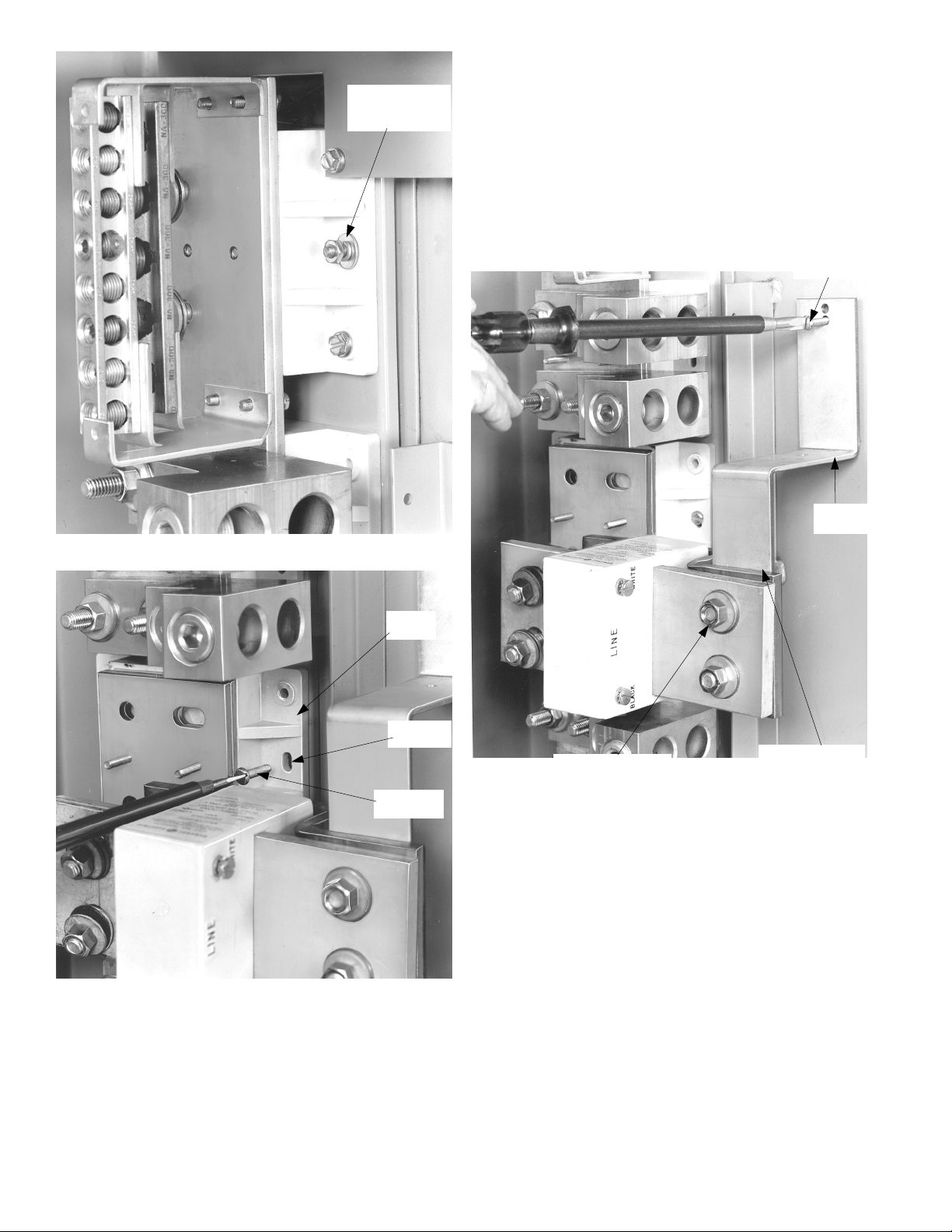
1. Remove the c onnection bar. Loosen the four nuts on
the studs (two in each strap) located at the current
transformer and at the load end of the neutral, as
shown in Figure 1. Slide out the connection bar
assembly.
Connection
Bar
Load End
of Neutral
2. Mount the neutral. Place the neutral in the desired
position in the en d of the b ox st amp ed
on the studs in the back of the box. as shown in Figure
2. Place a flat washer, lock washer, and nut on the
studs, as shown in Figure 3. Leave the nuts hand tight.
Align the elongated holes in the neutral with the
holes in the b ox and secure with eight #1 0-32 x
thread-forming screws, as shown in Figure 4. Tighten
the screws and nuts to 27–32 in.-lb.
LINE. Mount it
7
/8"
Stud (one
each side)
Nuts
Figure 1. Removing the connection bar assembly.
Current
Transformer
Figure 2. Neutral mounting position.
Page 2
#10 Flat Washer,
Lock Washer,
Figure 3. Mounting the neutral in the box.
Hex Nut
3. Mount the bond stra p. If a bonding s trap is required
for service entrance use, loosen the bolt at the line end
of the neutral transformer and slide the bond strap
under the head of the bolt, as shown in Figure 5. (For
NEMA 3R/12 enclosures go to step 4.) If the box is
painted, scratch through the paint in the area where
the bond str ap is to con tact the box. Secure the bond
3
strap to the box w ith on e #10-32 x
/8" thread-forming
screw. Tighten the screws to 27–32 in.-lb. Retighten
the nut at the other end of the bond strap at the
neutral transformer to 200–250 in.-lb.
#10-32 x
3
/8" Screw
Bond
Strap
Figure 4. Securing the neutral in position.
Neutral
Base
Elongated
Hole
#10-32 x
7
/8" Screw
Nut Washer (bolt
head on underside)
Slide Bond Strap
(with slot) under
Head of Bolt
Figure 5. Attaching a bond strap.
Page 3

4. Bond strap in NEMA 3R/12 enclosures. If a bond
strap is required for service entrance use, loosen the
bolt at the line end of the neutral transformer and
slide the bond strap under the head of the bolt.
Position the right-angle bracket so that the slotted
holes align with the holes in the bond strap and the
bracket in the back of the box, a s shown in Figure 6.
Secure with two #10-32 x
3
/8" thread-forming screws
and tighten to 2 7–32 in.-lb. Retighten the nut at the
other end of the bond strap at the neutral transformer
to 200–250 in.-lb.
Bond
Strap
#10-32 x
3
/8" Screws
Angle
Bracket
Box
Bracket
Nut Washer (bolt
head on underside)
Figure 6. Mounting a bond strap in a NEMA 3R/12 enclosure.
5. Replace the connect ion bar. Slide the connection bar
assembly back into position on the four studs, as
shown in Figure 1, and tighten the nuts to 200–250
in.-lb.
Page 4

These instructions do not cover all details or variations in equipment nor do they provide for every possible contingency that
may be met in connection with installation, operation, or mainten ance. Should further information be desired or should
particular problems arise that are not covered sufficiently for the purchaser’s purposes, the matter should be refer red to the
GE Company.
GE Industrial Systems
General Electric Company
41 Woodford Ave., Plainville, CT 06062
GEH5683 R02 1001 © 2001 General Electric Company
g
 Loading...