

Page 1
g
p
g
quip
p
y
quip
g
p
p
y
purp
g
WARNING: Danger of electrical shock or injury.
Turn
OFF
switchboard before workin
ment or removing any component. Do
e
not remove circuit
other component until the power is turned
OFF.
General
Table 1 is the list of parts supplied with this kit. Numbers
in brackets in the text and figures refer to the item
number in this table.
ower ahead of the panelboard or
inside the
rotective devices or an
GEH5925 Installation Instructions R02
Spectra Series™ Power Panelboards
Endwall Kit
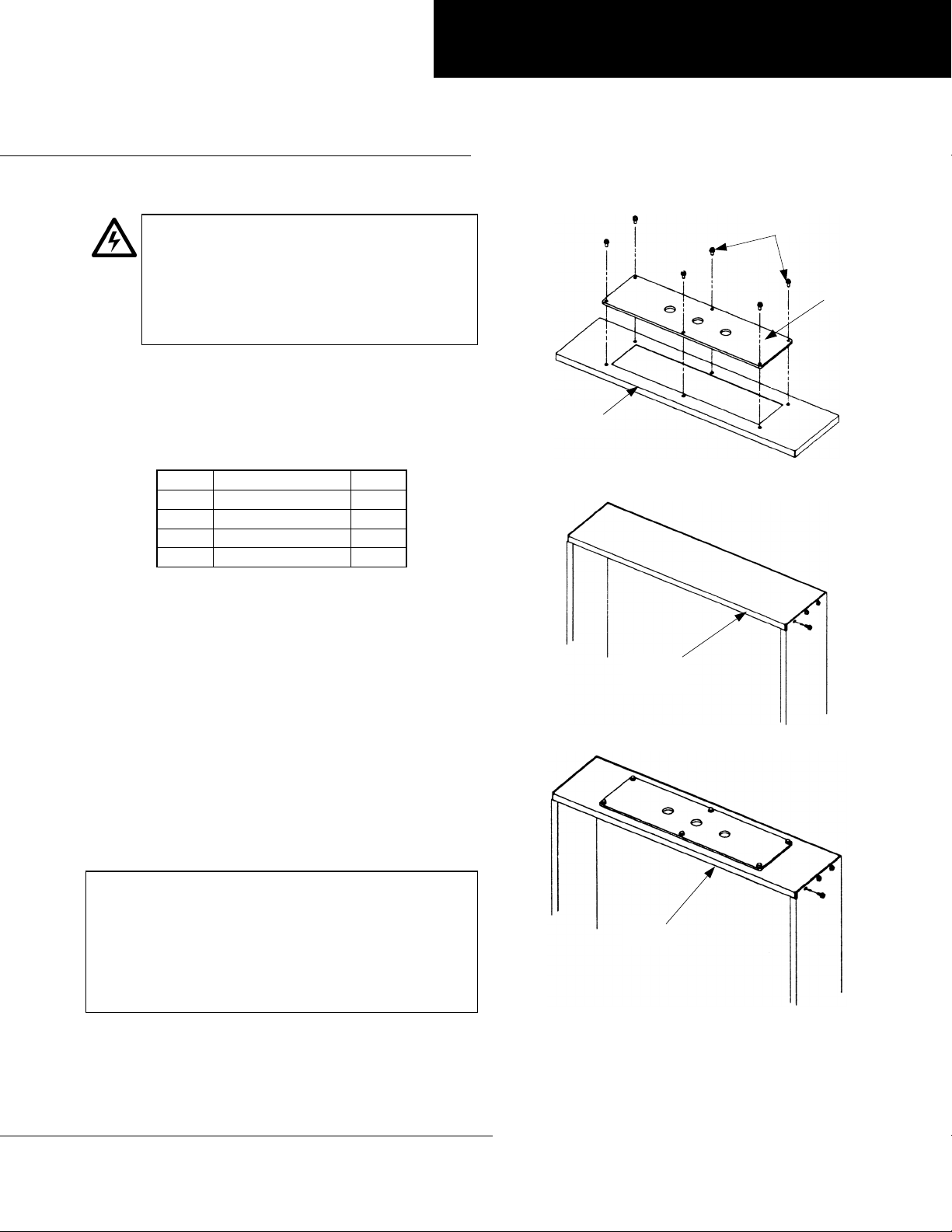
Screws
[4]
Plate
[2] or [3]
Endwall
[1]
Item Description Qty.
1 Endwall 2
2 Nonmetallic plate 1
3 Aluminum plate 1
1
4
/4-20 x 1/2" screws 12
Table 1. Parts included in the endwall kit.
Installation
Use the following procedure to install the endwall kit.
1. Cut holes into the nonmetallic plate [2] and the
aluminum plate [3] as required for wiring and as
shown in Figure 1.
2. Attach the nonmetallic plate [2] and the aluminum
plate [3] to the endwalls [1] with
[4], as shown in Figure 1.
3. Remove the existing endwalls from the panelboard
box, as shown in Figure 2. Do not discard the screws.
4. Attach the new endwalls to the panelboard box, as
shown in Figure 3, with the screws removed in step 3.
These instructions do not cover all details or variations in
e
ment nor do they provide for every possible
contin
installation, o
information be desired or should
that are not covered sufficientl
Company.
ency that may be met in connection with
eration, or maintenance. Should further
oses, the matter should be referred to the GE
1
/4-20 x 1/2" screws
articular problems arise
for the purchaser’s
Figure 1. Attaching the nonmetallic plate or the aluminum plate to an
endwall.
Remove
Existing
Endwall
Figure 2. Removing the existing endwall from the panelboard box.
New
Endwall
Figure 3. Attaching the new endwalls to the panelboard box.
GE Industrial Systems
General Electric Company
41 Woodford Ave., Plainville, CT 06062
GEH5925 R02 1001 © 2001 General Electric Company
 Loading...