

GE Industrial Solutions Spectra Series Power Panelboards Circuit Breaker Cover Plate User Manual
Page 1
g
p
g
quip
p
y
DEH044 Installation Instructions R02
Spectra Series™ Power Panelboards
Circuit Breaker Cover Plate
WARNING: Danger of electrical shock or injury.
OFF
Turn
switchboard before workin
ment or removing any component. Do
e
not remove circuit
other component until the power is turned
OFF.
ower ahead of the panelboard or
inside the
rotective devices or an
General
These instructions apply to the following circuit breaker
frames: TEY, THQB, and THHQB.
Installation
1. Select the breaker cover supports and breaker covers.
Table 1 lists the catalog numbers of the appropriate
cover supports for various switchboard and
panelboard sizes. Table 2 lists the breaker covers for
various breaker types.
Switchboard or Panelboard Width
Cover Height
41/8" (3X) 208C1850P4 208C1850P3 208C1850P3
Table 1. Circuit breaker cover support catalog numbers for various
27 & 31" Pnlbd
35" Swbd
panelboard and switchboard widths.
36 & 40" Pnlbd
40" Swbd
44" Pnlbd
45" Swbd
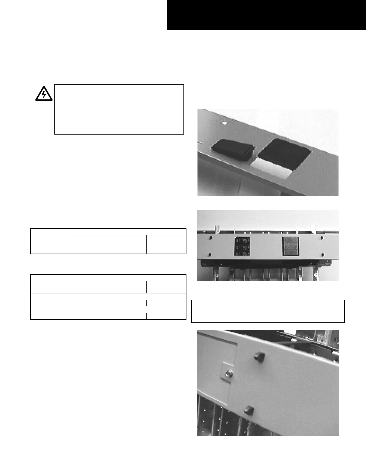
5. Install the circuit breaker cover. Snap the assembled
breaker cover over the flexible prongs on the filler
supports, as shown in Figure 2.
Figure 1. Attaching the space fillers to the filler plate.
Switchboard or Panelboard Width
Cover Height
51/2" (4X) 208C4262G10 208C4262G11 208C4262G12
51/2" (4X) 208C4262G13 208C4262G14 208C4262G15
Table 2. Circuit breaker cover catalog numbers for various
2. Install the circuit breaker cover supports. Attach the
breaker cover supports selected in step 1 to the
breaker module or to the breaker mounting plates,
according to the breaker mounting instructions.
3. Install the circuit breakers according to the
instructions provided with the breakers.
4. Install the space fillers to any holes in the filler plate
with no breakers mounted behind. Use the plastic
space filler.
Install the filler from the top side of the breaker cover
plate. Engage the slotted end of the space filler with
the edge of the opening in the breaker cover. Snap
the other end of the filler into place, as shown in
Figure 1.
27 & 31" Pnlbd
35" Swbd
THQB, THHQB – Double-branch mount
TEY – Double-branch mount
panelboard and switchboard widths.
36 & 40" Pnlbd
40" Swbd
44" Pnlbd
45" Swbd
Figure 2. Installing the breaker cover to the filler supports.
CAUTION: To ensure secure mounting, push the breaker
cover completely over the four flexible prongs on top of
the filler supports, as shown in Figure 3.
Figure 3. Breaker cover securely mounted on the flexible prongs.
Page 2

NOTE: Push-on breaker covers may bend if not removed
g
quip
y
p
properly. Pull the upper edge of the breaker cover off the
flexible prongs, then pull the lower edge free.
These instructions do not cover all details or variations in e
ma
be met in connection with installation, operation, or maintenance. Should further information be desired or should
articular problems arise that are not covered sufficiently for the purchaser’s purposes, the matter should be referred to the
GE Company.
ment nor do they provide for every possible contingency that
GE Industrial Systems
General Electric Company
41 Woodford Ave., Plainville, CT 06062
DEH044 R02 0801 © 2001 General Electric Company
 Loading...