

Page 1
GEH5581 Installation Instructions R03
-
g
Spectra Series™ Power Panelboards
60 A/600 V, 100 A/240 V, 100 A/600 V Expansion Kits for
Type ADS Fusible Switch Units
WARNING: Danger of electrical shock or injury.
Turn
OFF power ahead of the panelboard or
switchboard before working inside the
equipment or removing any component
not remove circuit protective devices or any
other component until the power is turned
OFF.
. Do
Installing the Expansion Kit
1. Remove the fusible switc h unit from the panelboard
or switchboard. Remove the load-s ide wires from the
switch load-side terminal. Loosen the rail latch
screws on each side of the switch unit and remove
the switch by pulling up on both latch handles, as
shown in Figu re 1, while p ulling the dev ice from the
panelboard.
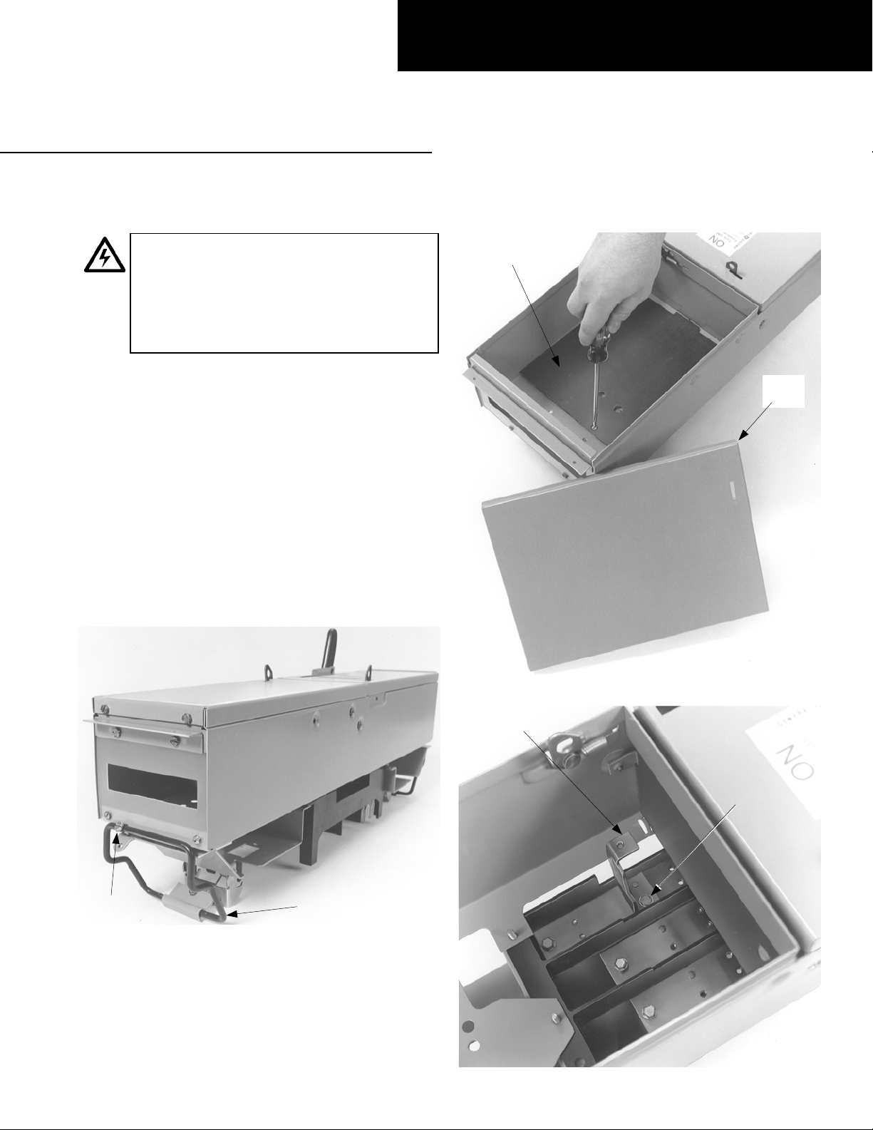
2. Prepare the enclosure. Remove and discard the
blank cover and the bottom insulator from the
bottom of the device, as shown in Figure 2.
3. Install the straps. Install the connecting straps with
the #10-32 x
shown in Figure 3. Tighten the screws to 27–32 in-lb.
1
/2" mounting screws provided, as
Bottom Fiber
Insulator
Blank
Cover
Rail Latch
Screw
Figure 1. Removing the fusible switch from the equipment.
Latch
Handle
Figure 2. Removing the blank cover and bottom insulator.
Connecting
Strap
#10
32 x 1/2"
Screw
Figure 3. Installing the connecting straps.
Page 2
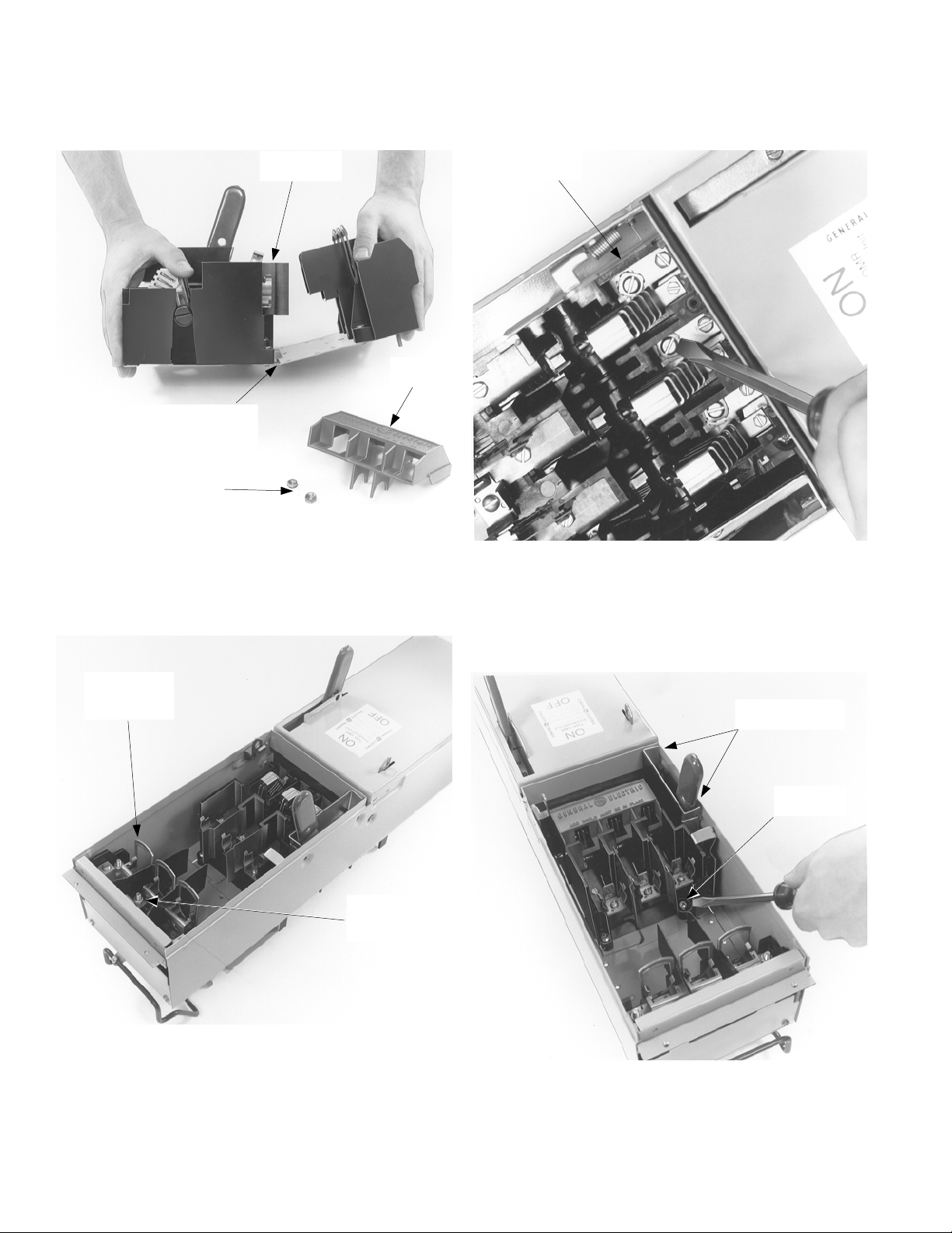
4. Prepare the switch. Remove and save the hex nuts
from the studs and red arc cover on the expansion
switch. When installing a 60- or 100-ampere, 600-volt
expansion switch, you must bend the expansion
switch unit 10 to 15 degrees, as shown in Figure 4.
Expansion
Switch Unit
Red Arc
Cover
Bend (for 60 or 100
A, 600 V switch only,
bend 10–15°)
6. Make the el ectrical connections. Install #10-32 screws
with washers into the connecting straps inside the
switch base, as shown in Figure 6, and tighten the
screws to 27–32 in-lb. Replace the red arc cover onto
the switch and tighten the screws to 9–11 in-lb.
#10-32 Screw
with Washers
Hex Nuts
Figure 4. Preparing the switch for installation.
5. Install the kit. Position the load side of the expansion
plate down into the enclosure, then place the switch
base over the connecting straps, as shown in Figure 5.
Replace the hex nuts on the plate studs and tighten
to 27–32 in-lb.
Insert Load
Side of Switch
(Plate) First
Install Hex
Nuts on Plate
Studs
Figure 6. Making the electrical connections.
7. Install the screws. Tighten the switch base screw to
27–32 in-lb, as shown in Figure 7. Install the #10-32 x
1
/4" handle assembly mounting screws into the
mechanism shroud mounting holes and tighten to
27–32 in-lb.
Handle Assembly
Mounting Screws
Switch Base
Screw
Figure 5. Install the expansion switch into the enclosure.
Figure 7. Installing the handle mounting screws.
Page 3

8. Install the cover. Position the new enclosure cover in
place on the enclosure, as shown in Figure 8, and
secure to the hinge with #10-32 x
1
/4" screws
tightened to 27–32 in-lb. Reinstall the fusible switch
unit and secure it to the rail locking screws.
Enclosure
Cover
Cover
Mounting
Screws
For Two-Pole Devices on Three-Phase
Systems Only
To balance the panelboard load, r e move the screws on the
appropriate bus clip, reposition the bus clip as shown in
Figure 9, then install and tighten the screws to 27–32 in-lb.
A & C Phase
As Received
A & B Phase
B & C Phase
Figure 8. Installing the cover on the enclosure.
Figure 9. Repositioning the bus clip to balance the load.
Page 4

These instructions do not cover all details or variations in equipment nor do they provide for every possible contingency that
may be met in connection with installation, operation, or maintenan ce. Should further information be desired or should
particular problems arise that are not covered sufficiently for the purchaser’s purposes, the matter should be refer red to the
GE Company.
GE Industrial Systems
General Electric Company
41 Woodford Ave., Plainville, CT 06062
GEH5581 R03 0601 © 2001 General Electric Company
g
 Loading...