

GE Industrial Solutions Spectra Series Power Panelboards 30–60 Ampere Expansion Kit User Manual
Page 1
GEH5547 Installation Instructions R02
g
Spectra Series™ Fusible Switch Units
30/60 Ampere Expansion Kit
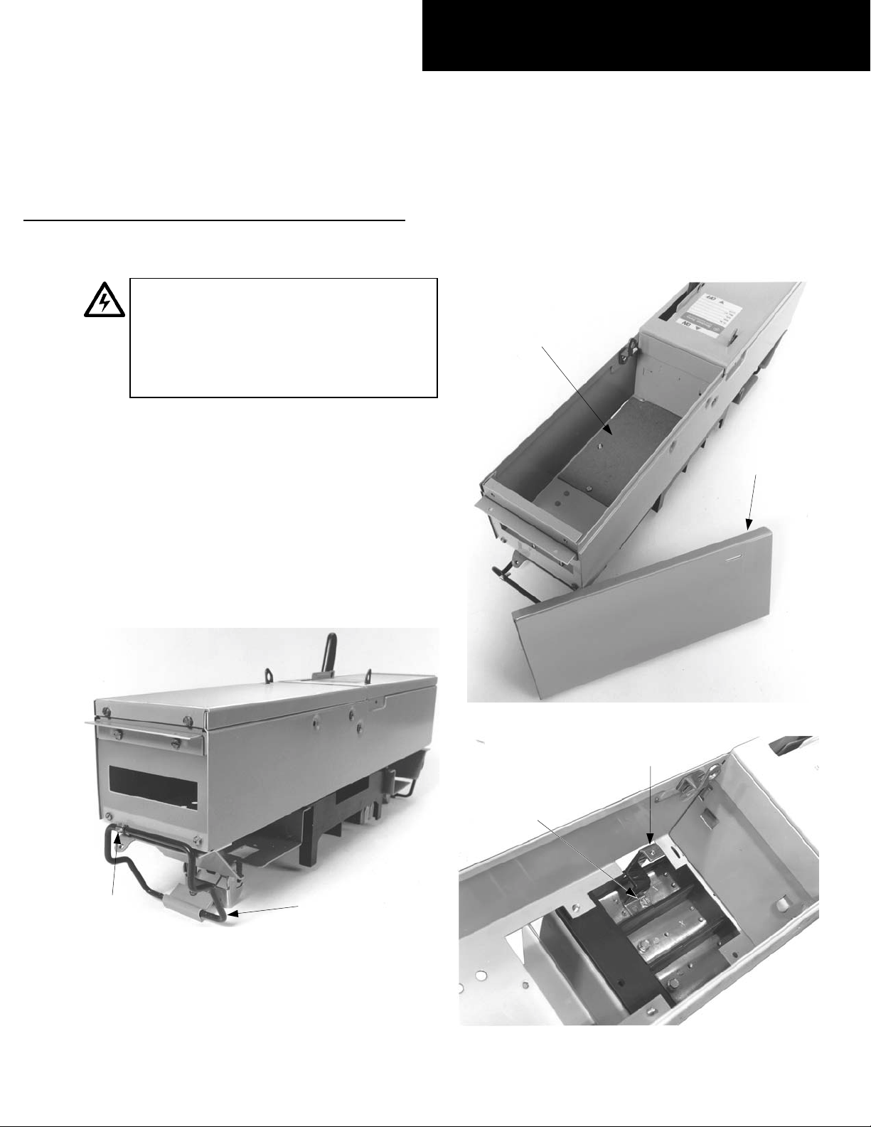
WARNING: Danger of electrical shock or injury.
Turn
OFF power ahead of the panelboard or
switchboard before working inside the
equipment or removing any component
not remove circuit protective devices or any
other component until the power is turned
OFF.
. Do
Bottom Fiber
Insulator
Installing the Expansion Kit
1. Remove the switch. Loosen the rail latch screws
and remove the switch by pulling up on the latch
handles while pulling the device from the
equipment, as shown in Figure 1.
2. Prepare the enclosure. Remove and discard the
blank cover and the bottom insulator from the
bottom of the device, as shown in Figure 2.
3. Install the straps. Install the connecting straps
with the 10-32
Figure 3. Tighten the screws to 27–32 in-lb.
1
x
/2" screws provided, as shown in
Blank
Cover
Figure 2. Removing the blank cover and bottom insulator.
Connecting
Strap
Screw
1
/2"
#10-32 x
Rail Latch
Screw
Figure 1. Removing the switch from the equipment.
Latch
Handle
Figure 3. Installing the connecting straps.
Page 2
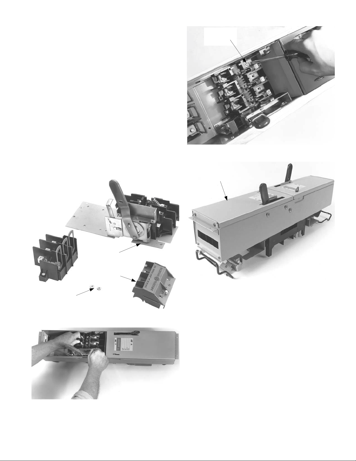
4. Prepare the switch. Remove and save the hex nuts
from the studs , the red arc cov er, and the load bas e
on the expansion switch, as shown in Figure 4.
5. Install the kit. Position the switch base over the
connecting straps, as shown in Figure 5. Replace the
load base and the hex nuts on the plate studs.
Tighten the nuts to 27– 32 in -lb. tur n the s witch b ack
over to its upright position.
6. Make the connections. Install #10-32
1
x
/4" screws
into the mechanism shroud mounting holes, as
shown in Figure 6. Install #10-32 screws with washers
into the str aps inside the s witch base and tighten to
27–32 in-lb. Invert the switch and replace the hex
nuts on the studs. Tighten the nuts to 27–32 in-lb.
7. Install the cover. Replace the endwall barrier and
mounting screws, as shown in Figure 7. Install the
red arc cover on the switch base and tighten the
mounting screws. Position the new en closure cover in
place on the enclosure and secure the hinge with
#10-32
1
x
/4" screws. Tighten the screws to 27–32 inlb. Reinstall the switch in the panelboard and secure
the rail latch locking screws.
#10-32 x 1/4"
Screw with
Washer
Figure 6. Making the connections.
Enclosure
Cover
Load
Base
Red Arc
Cover
Hex Nuts
Figure 4. Removng the hex nuts from the switch.
Figure 5. Installing the expansion kit.
Figure 7. Installing the cover on the enclosure.
Page 3

For Two-Pole Devices on Three-Phase
Systems Only
To balance the panelboard load, r e move the screws on the
appropriate bus clip, reposition the bus clip as shown in
Figure 8, then reinstall and tighten the screws to 27–32 inlb.
A & C Phase
As Received
A & B Phase
B & C Phase
Figure 8. Repositioning the bus clip to balance the load.
Page 4

These instructions do not cover all details or variations in equipment nor do they provide for every possible contingency that
may be met in connection with installation, operation, or mainten ance. Should further information be desired or should
particular problems arise that are not covered sufficiently for the purchaser’s purposes, the matter should be refer red to the
GE Company.
g
GE Industrial Systems
General Electric Company
41 Woodford Ave., Plainville, CT 06062
GEH5547 R02 0501 © 2001 General Electric Company
 Loading...