

GE Industrial Solutions Spectra Series Power Panelboards 30–200 Ampere Fusible Switch User Manual
Page 1
g
p
g
quip
p
y
p
GEH5548 Installation Instructions R02
Spectra Series™ Power Panelboards
30–200 Ampere Fusible Switch
WARNING: Danger of electrical shock or injury.
OFF
Turn
switchboard before workin
ment or removing any component. Do
e
not remove circuit
other component until the power is turned
OFF.
ower ahead of the panelboard or
inside the
rotective devices or an
General
To comply with the National Electrical Code and
Underwriters Laboratories, the Canadian Electrical Code
and the Canadian Standards Association, the load center
must be installed in accordance with the information
included on the label on the inside of the equipment.
This must also be done in accordance with the applicable
local electrical codes and by a qualified electrical
contractor or licensed electrician.
WARNING: Hazard of electrical shock or burn.
Turn off
before working inside.
ower supplying this equipment
Installation
Use the following instructions to install a 30–200 ampere
fusible switch.
1. Remove the mounting bracket. Remove the two screws
shown in Figure 1 and remove the mounting bracket
from the switch.
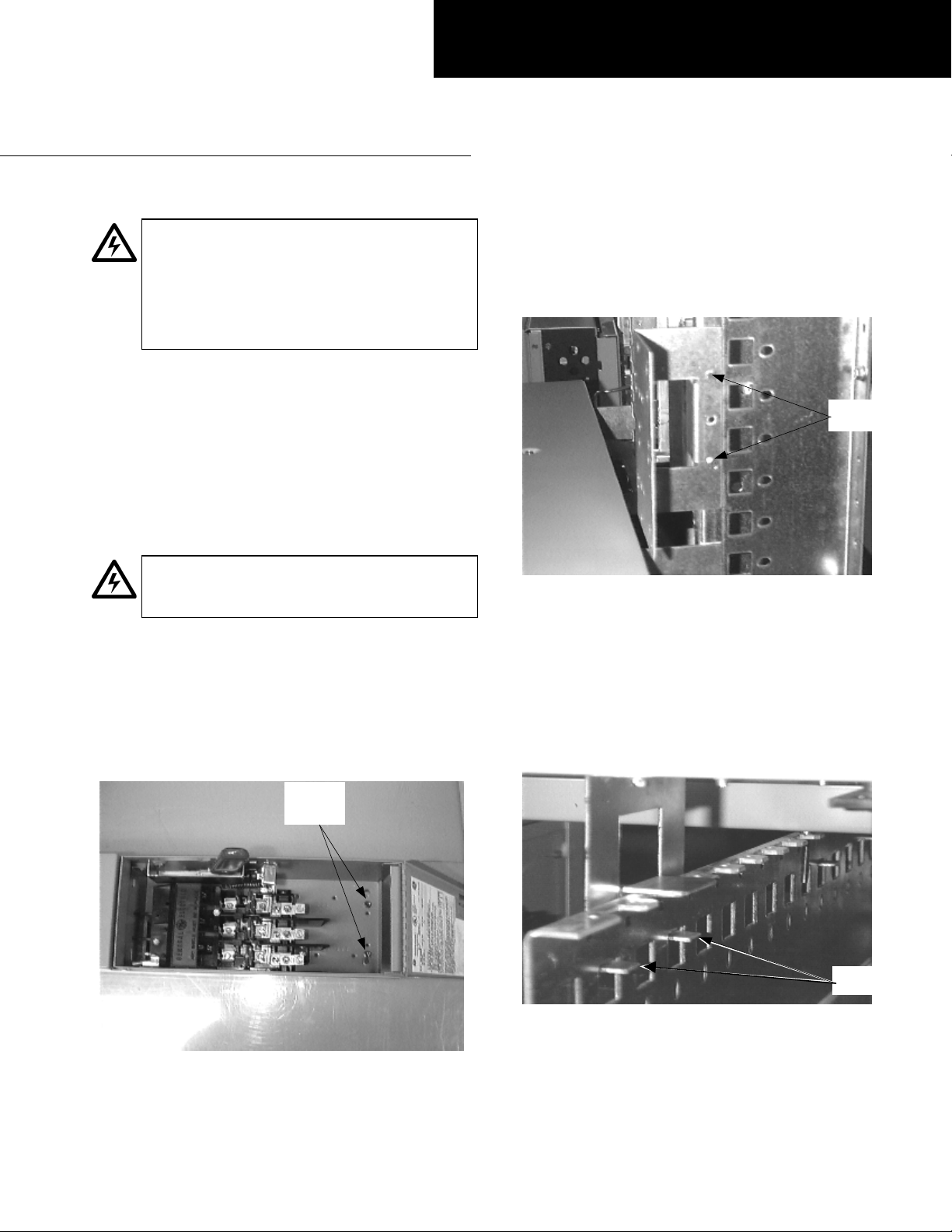
2. Mount the removable mounting bracket. Install the
mounting bracket (removed from the switch in step 1)
on the power panelboard with the two self-tapping
screws provided, as shown in Figure 2. Tighten the
screws to 27–32 in-lb.
Mounting
Screws
Figure 2. Installing the mounting bracket in the panelboard.
3. Install the switch. Align the locating hook tabs on the
bottom of the switch into the square holes in the
support rails on the panelboard interior, as shown in
Figure 3. Open the switch door and reattach the
screws removed in step 1 to the mounting bracket
installed on the panel in step 2. Tighten the screws to
27–32 in-lb.
Mounting
Bracket
Screws
Figure 1. Removing the mounting bracket from the switch.
Locating
Tabs
Figure 3. Switch locating tabs aligned in the panelboard interior.
Page 2

4. Wire the circuits. Refer to the label inside for the
g
quip
y
p
switch cover for the proper tightening torques.
5. Filler plates. Install filler plates in all unused spaces
from the filler kits included with the switch. Order
replacement filler plates from the list in Table 1.
Current,
A Voltage
30 240/600 H, J, K, R 26 AFP4X
60
100 240/600
200 240/600
240 H, K, R AFP4X
600 H, J, K, R
Fuse
Type
H, J, K, R AFP5X
T, J 26 AFP7T
H, J, K, R 26 AFP7X
H, K, R 32 AFP7X2
T
Switch Encl.
Width, in.
26
26
Filler Kit
Cat. No.
AFP5X
AFP7T
Table 1. Replacement filler plate kits.
Procedure for Aluminum Terminations
1. Strip the insulation, being careful to not nick the wire.
2. Clean the wire strands with a wire brush.
3. Thoroughly coat the stripped conductor with a
suitable antioxidant compound, such as ALNOX or
PENETROX A13.
4. Insert the conductor and tighten the connector screw
to the torque indicated on the rating label.
For Two-Pole Devices on Three-Phase
Systems Only
To balance the panelboard load, remove the screws on the
appropriate bus clip, reposition the bus clip as shown in
Figure 8, then reinstall and tighten the screws to 27–32 inlb.
A & C Phase
As Received
A & B Phase
B & C Phase
Figure 4. Repositioning the bus clip to balance the load.
These instructions do not cover all details or variations in e
ma
be met in connection with installation, operation, or maintenance. Should further information be desired or should
articular problems arise that are not covered sufficiently for the purchaser’s purposes, the matter should be referred to the
GE Company.
ment nor do they provide for every possible contingency that
GE Industrial Systems
General Electric Company
41 Woodford Ave., Plainville, CT 06062
GEH5548 R02 0901 © 2001 General Electric Company
 Loading...