

Page 1
GEH5889 Installation Instructions R02
g
Spectra Series™ Fusible Switch Units
200 Ampere Expansion Kit (H, K, and R Fuses)
WARNING: Danger of electrical shock or injury.
Turn
Installing the Expansion Kit
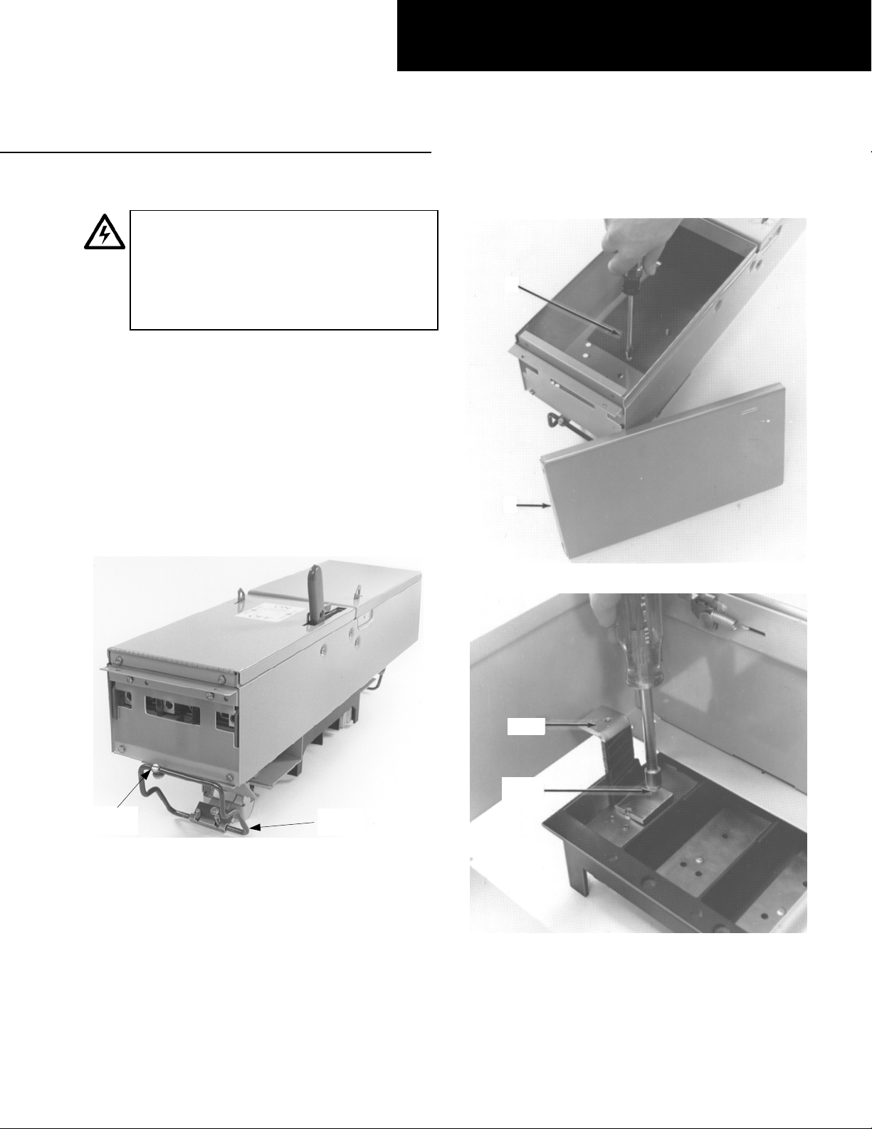
1. Remove the switch. Loosen the rail latch screws and
remove the s wi tch b y pu ll in g u p on the la tc h han dle s
while pulling the device from the equipment, as
shown in Figure 1.
2. Prepare the enclosure. Remove and discard the
blank cover and the bottom insulator from the
bottom of the device, as shown in Figure 2.
3. Install the straps. Install the connecting straps with
the 10-32 x
3. Tighten the screws to 27–32 in-lb.
OFF power ahead of the panelboard or
switchboard before working inside the
equipment or removing any component
not remove circuit protective devices or any
other component until the power is turned
OFF.
1
/2" screws provided, as shown in Figure
. Do
Bottom
Insulator
Blank
Cover
Figure 2. Removing the blank cover and bottom insulator.
Rail Latch
Screw
Figure 1. Removing the switch from the equipment.
Latch
Handle
Strap
#10-32
Screw
Figure 3. Installing the connecting straps.
Page 2
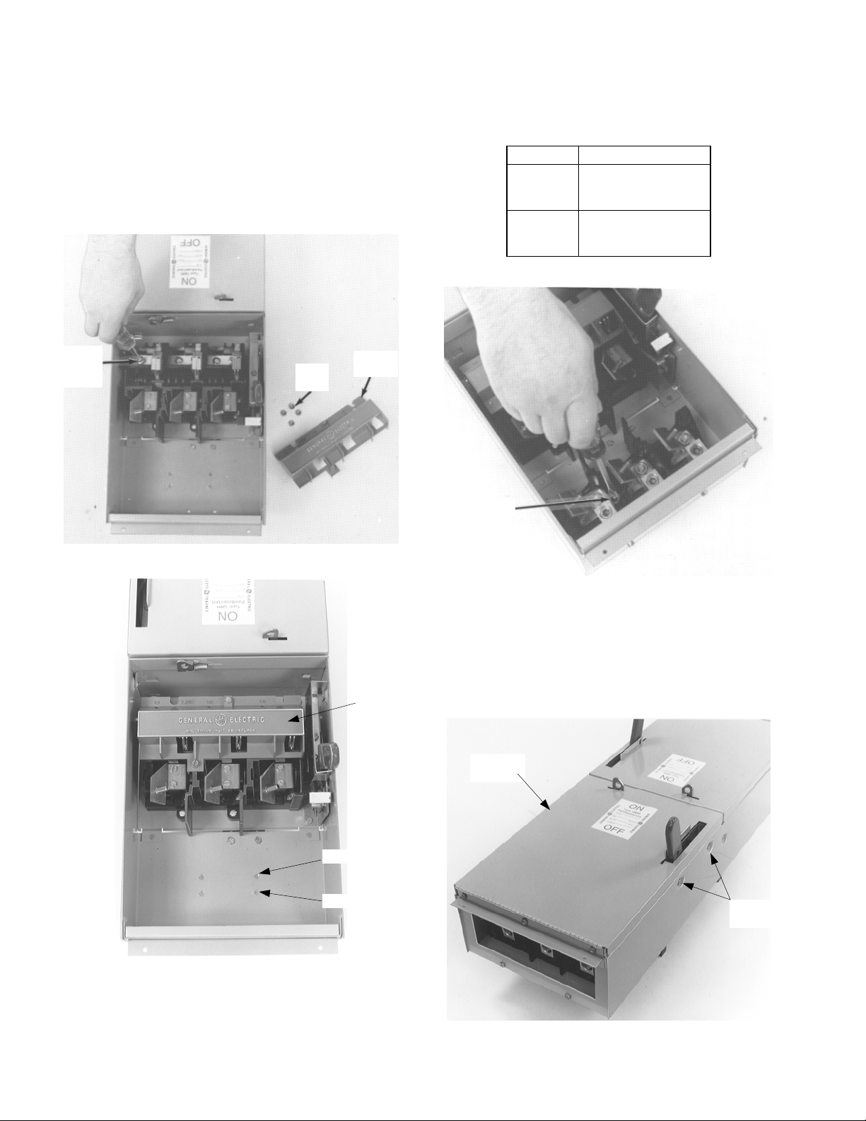
4. Install the kit. Remove and save the hex nuts from
the studs and the red arc cover on the expansion
switch, as shown in Figure 4. Install the expansion
plate into the enclosure, positionin g the switch base
over the connecting straps. Install 10-32 screws with
washers into the connecting straps inside the switch
base. Tighten the screws to 27–32 in-lb.
Replace the hex nuts back onto the plate stu ds and
tighten to 27–32 in-lb. Replace the red arc cover, as
shown in Figure 5, and tighten the screws to 12–15
in-lb.
5. Install the load base. Install the load base into the
enclosure, as shown in Figure 6. The position
depends on the fuse type, as illustrated in Figure 5
and listed in Table 1. Tighten the mounting screws
to 40–50 in-lb.
Position Fuse Type
1
2
H Fuse 240 V
K Fuse 240 V
R Fuse 240 V
H Fuse 600 V
K Fuse 600 V
R Fuse 600 V
Table 1. Position for the load base in the enclosure.
#10-32
Screw with
Washer
Figure 4. Installing the expansion plate into the enclosure.
Hex
Nuts
Red Arc
Cover
Arc
Cover
Load
Base
Figure 6. Installing the load base.
6. Install the cover. Install 10-32 x
mechanism shroud mounting holes, as shown in
Figure 7. Position the new enclosure cover in place
on the enclosure and secure with 10-32 x
Tighten all screws to 27–32 in-lb. Reinstall the switch
into the panelboard and secure the rail latch locking
screws.
Enclosure
Cover
1
/4" screws into the
1
/4" screws.
Figure 5. Replacing the arc cover.
Position 1
Position 2
Mounting
Holes
Figure 7. Installing the cover on the enclosure.
Page 3

For Two-Pole Devices on Three-Phase
Systems
To balance the panelboard load, r e move the screws on the
appropriate bus clip, reposition the bus clip as shown in
Figure 8, then install and tighten the screws to 27–32 in-lb.
A & C Phase
As Received
A & B Phase
B & C Phase
Figure 8. Repositioning the bus clip to balance the load.
Page 4

These instructions do not cover all details or variations in equipment nor do they provide for every possible contingency that
may be met in connection with installation, operation, or mainten ance. Should further information be desired or should
particular problems arise that are not covered sufficiently for the purchaser’s purposes, the matter should be refer red to the
GE Company.
GE Industrial Systems
General Electric Company
41 Woodford Ave., Plainville, CT 06062
GEH5889 R02 0901 © 2001 General Electric Company
g
 Loading...