

Page 1
g
p
g
quip
y
This publication describes the installation of type ADF
dead fronts and type APF door fronts onto types APN and
APNB power panelboard interiors.
WARNING: Danger of electrical shock or injury.
OFF
Turn
switchboard before workin
ment or removing any component.
e
Equipment is to be installed and maintained b
properly trained and qualified personnel only.
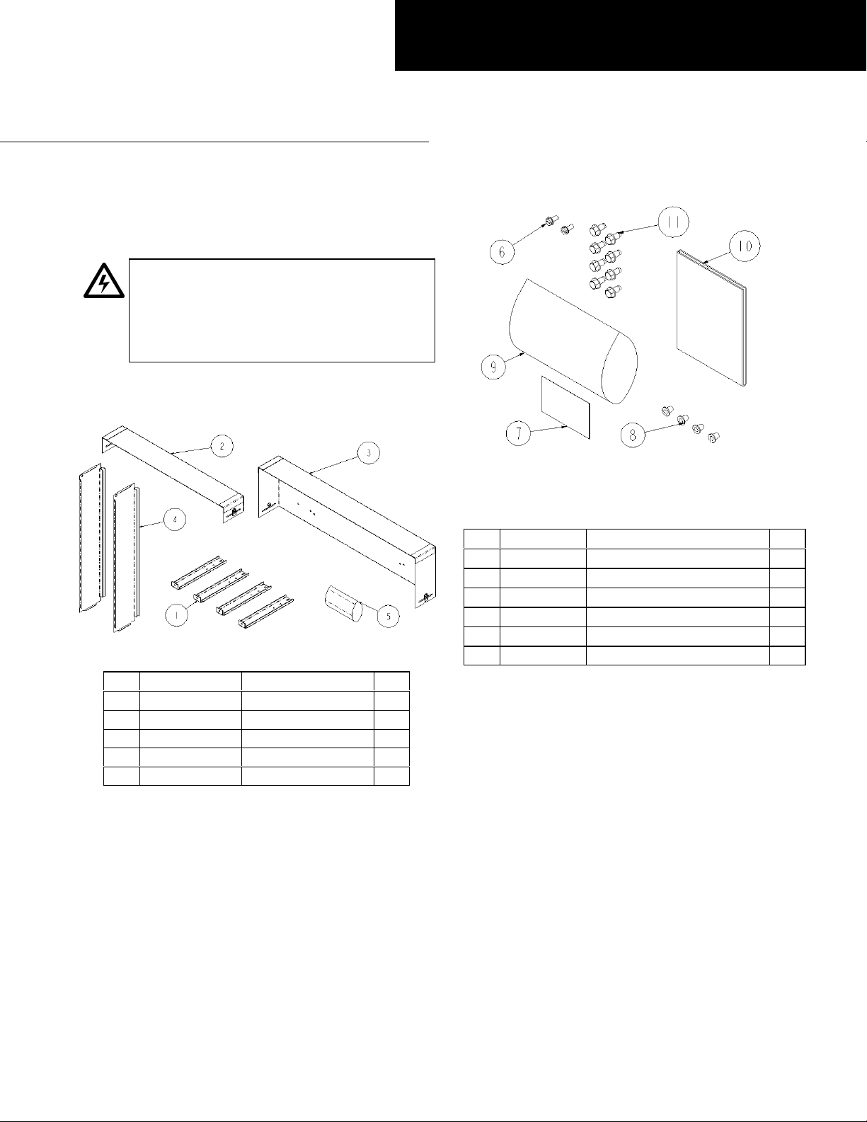
The parts in the dead front kit are illustrated in Figures 1
and 2, with the parts listed in Tables 1 and 2.
ower ahead of the panelboard or
inside the
GEH5930 Installation Instructions R04
Spectra Series™ Power Panelboards
Type ADF Dead Fronts & Type APF Door Fronts
Figure 1. Parts included in the type ADF dead front kit.
Item Cat. No. Description Qty.
1 208C2022P1 Mounting post
2 Varies with kit Dead front load end
3 Varies with kit Dead front line end
4 Varies with kit Dead front side
5 10085396G1 Hardware kit
Table 1. Parts list for the type ADF dead front kit (see Figure 1).
4
1
1
2
1
Figure 2. Parts included in the hardware kit of the type ADF dead
front.
Item Cat. No. Description Qty.
6 192A6976P189 #10-32 x 7/16 screw
7 252B2269P2 Label
8 331A2631P2 Plug
9 44A718891P2 Poly bag
10 GEH5930 Installation instructions
11 N722P21008B61/4-20 x 1/2 screw
Table 2. Parts included in the hardware kit (see Figure 2).
2
1
4
1
1
8
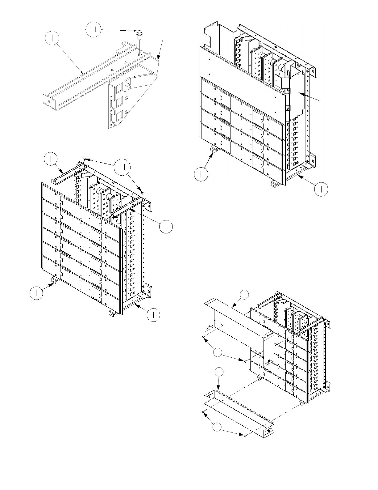
Installing the Dead Front
The numbers in brackets in the text and indicated in the
figures refer to the items in Tables 1 and 2.
1. Install the four dead-front mounting posts [1] before
the panel is mounted in the enclosure. Fasten one
post to either end of the top and bottom interior end
plates at the outermost holes, using the
in. hex-head screws [11] provided, as illustrated in
Figure 3 and Figure 4. Tighten the screws to 50–60 in.lbs.
For interiors equipped with main lug assemblies,
mounting posts are needed only on the load end, as
shown in Figure 5.
1
/4-20 x 1/2-
Page 2
Interior
End Plate
Figure 3. Attaching a dead front mounting post to the interior end
plate.
Main Lug
Bracket
Figure 5. Dead front posts mounted only on the load end of a dual
main lug interior.
2. Fasten the dead front load end [2] to the mounting
1
posts located opposite the line side, using the
1
/2-in. hex-head screws [11] provided, as illustrated in
/4-20 x
Figure 6. Repeat the process for the dead front line
end [3] onto the mounting posts located on the line
side of the panel. Tighten the screws to 50–60 in.-lbs.
For interiors with main lugs, fasten the dead front line
end [3] to the main lug brackets with the #10-32
7
/16-in. screws [6] provided, as illustrated in Figure 7.
Tighten the screws to 25–30 in.-lbs.
x
Figure 4. Dead front mounting posts mounted at the four corners of
the interior.
3
11
2
11
Figure 6. Installing the dead front load and line ends to the mounting
posts. Note that a top-feed installation is shown; reverse [2] and [3]
for bottom feed.
Page 3

3
6
2
11
Main Lug
Bracket
Figure 7. Installing the dead front load and line ends to an interior
with main lugs.
3. Turn the latches on the ends of the dead front line
end [3] and load end [2] so that the slot openings are
clear. Align the flanges on the dead front end side
panels [4] into the slots on the ends, as shown in
Figure 8. Turn the latches a quarter turn to secure the
end panels. Figure 9 shows the completed dead front
assembly.
3
Figure 9. Completed dead front assembly.
Installing the Door Front
4. Orient the door with the hinges to the right, as shown
in Figure 10. Align the door with the enclosure side
walls, and rest the welded brackets located at the lower
back side of the door on the enclosure end wall, as
illustrated in Figure 11. Fasten the door to the
enclosure with the #10-32 x
screws provided. Tighten all screws to 25–30 in.
11
/16-in. self-tapping
4
Latch
2
Figure 8. Installing the dead front side panels to the line and load
ends.
4
Door
Hinge
Screw
Reference
Figure 11
Figure 10. Installing the door front.
Page 4

quip
g
p
g
Bracket
Enclosure
Figure 11. Attaching the door to the enclosure end wall.
Installation is now complete. Reverse the installation steps
to remove the door and/or dead front to gain access to
the wiring spaces in the enclosure. Turn off power ahead of
the panel before performing any maintenance in wiring
areas.
Door
Screw
These instructions do not cover all details or variations in e
contin
information be desired or should
purposes, the matter should be referred to the GE Company.
ency that may be met in connection with installation, operation, or maintenance. Should further
articular problems arise that are not covered sufficiently for the purchaser’s
GE Industrial Systems
General Electric Company
41 Woodford Ave., Plainville, CT 06062
GEH5930 R04 0601 © 2001 General Electric Company
ment nor do they provide for every possible
 Loading...