

Page 1
g
p
g
quip
y
DEH40443 Installation Instructions R02
Spectra Series™ Power Panelboards &
Switchboard Panels
ACT Transient-Voltage Surge Suppressors
Application
These kits are provided for installation of ACT TransientVoltage Surge Suppressor (TVSS) in Spectra bolt-on and
plug-in panels and switchboards. The catalog numbers
and descriptions of the available units are listed in Table
1. The K suffix denotes field-installable kits.
5
All TVSS units are 7X (9
equipment width is a 27-inch wide Spectra panelboard or
35-inch wide Spectra switchboard.
System
Catalog Number
ATME120S065K 120/240 1Ø 65
ATME120S800K 120/240 1Ø 80
ATHE120S100K 120/240 1Ø 100
ATHE120S150K 120/240 1Ø 150
ATHE120S200K 120/240 1Ø 200
ATME120Y065K 208Y/120 3Ø, 4W 65
ATME120Y800K 208Y/120 3Ø, 4W 80
ATHE120Y100K 208Y/120 3Ø, 4W 100
ATHE120Y150K 208Y/120 3Ø, 4W 150
ATHE120Y200K 208Y/120 3Ø, 4W 200
ATME240D065K 240 ∆ 3Ø, 3W 65
ATME240D080K 240 ∆ 3Ø, 3W 80
ATHE240D100K 240 ∆ 3Ø, 3W 100
ATHE240D150K 240 ∆ 3Ø, 3W 150
ATHE240D200K 240 ∆ 3Ø, 3W 200
ATME277Y065K 480Y/277 3Ø, 4W 65
ATME277Y080K 480Y/277 3Ø, 4W 80
ATHE277Y100K 480Y/277 3Ø, 4W 100
ATHE277Y150K 480Y/277 3Ø, 4W 150
ATHE277Y150K 480Y/277 3Ø, 4W 200
ATME480D065K 480 ∆ 3Ø, 3W 65
ATME480D080K 480 ∆ 3Ø, 3W 80
ATHE480D100K 480 ∆ 3Ø, 3W 100
ATHE480D150K 480 ∆ 3Ø, 3W 150
ATHE480D200K 480 ∆ 3Ø, 3W 200
ATME240H065K 240/120 ∆ 3Ø, 4W 65
ATME240H080K 240/120 ∆ 3Ø, 4W 80
ATHE240H100K 240/120 ∆ 3Ø, 4W 100
ATHE240H150K 240/120 ∆ 3Ø, 4W 150
ATHE240H200K 240/120 ∆ 3Ø, 4W 200
Table 1. Catalog numbers and specifications for ACT transient-
Voltage, Vac Configuration
voltage surge suppressor kits.
/8") high and the minimum
Surge
Current per
Mode, kA
Installation
WARNING: Danger of electrical shock or injury.
OFF
Turn
switchboard before workin
e
ment or removing any component.
Equipment is to be installed and maintained b
properly trained and qualified personnel only.
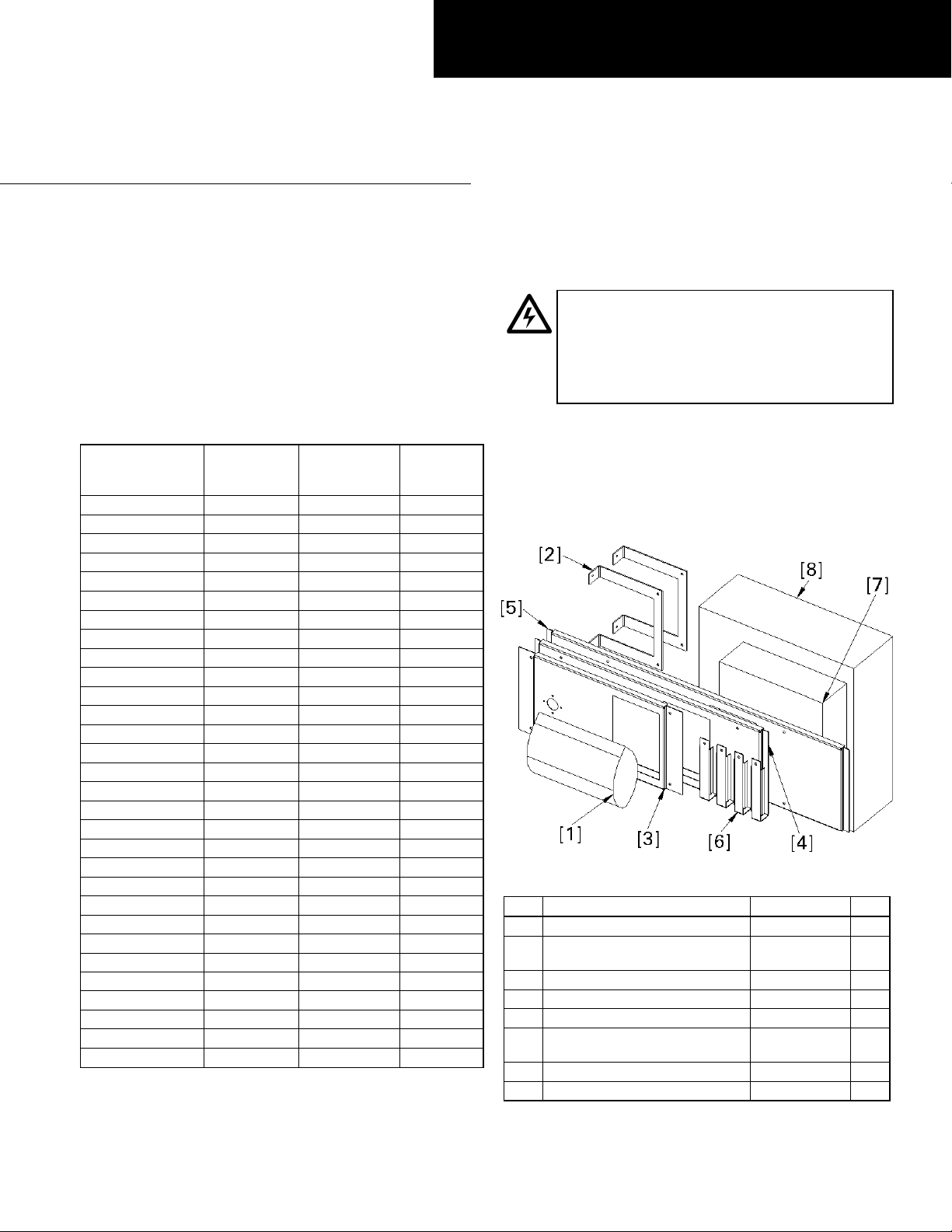
The numbers in brackets in the text and figures refer to
the items in Tables 2 and 3.
1. Confirm the contents of the kit. Figure 1 illustrates the
contents of the kit, with the parts listed in Table 2.
Figure 2 illustrates the hardware included in the kit
([1] in Table 2), with the parts listed in Table 3.
Figure 1. Typical TVSS kit contents.
Item Description Part # Qty.
1 TVSS kit hardware 10082305G3 1
Cover support for 36W, 40W,
2
44W, and 45W
3 Cover for 27W, 31W and 35W 10087203G1 1
4 Cover for 36W and 40W 10087203G2 1
5 Cover for 44W and 45W 10087203G3 1
Cover support for 27W, 31W
6
and 35W
7 Neutral and ground wire kit ATHMEGNDN 1
8 TVSS in package TVSS_UNIT 1
Table 2. Parts list for the TVSS kit.
ower ahead of the panelboard or
inside the
10083033P2 2
252B1477P4 4
Page 2
Figure 2. Contents of the hardware package [2] included with the
TVSS kit.
Item Description Part # Qty.
9 Cable assembly 10080794G1 3
10 Spacer, .70 inch 188A4381P9 3
Thread-forming screw,
11
10-32x
12 Conical spring washer, 1/4" 75A105503P101 3
13 Conical spring washer, 3/8" 75A105503P102 3
14 TVSS instruction sheet DEH40443 1
15 Nut, 1/4-20 N245P21B6 3
16 Nut, 3/8-16 N245P25B6 3
17 Carriage bolt, 1/4-20 x 2" N657P21032B6 3
18 Carriage bolt, 3/8-16 x 2" N657P25032B6 3
7
/16"
192A6976P189 12
Table 3. Parts list for the hardware package [2].
2. Install TVSS bus cable assembly.
• Bolt-on and single bus of plug-in assemblies, switchboard
panels, and powerpanels. Before installing, locate the
side of the panel interior for which the dimension
from the nearest vertical bus face to the inner face
of the bus support rail is 2.75 inches, as indicated
in Figure 3. The cable terminals will be mounted
on this side of the bus.
For each phase install a
1
/4-20 x 2" carriage bolt
[17] into a .281-inch square hole of the interior
vertical bus, as shown in Figure 4. Use the
5
uppermost holes in the 7X (9
/8") space that the
TVSS unit can reach. Slide a terminal of the cable
assembly [9] onto each carriage bolt and rotate it
so that the terminal barrel is located below the front
1
edge of the vertical bus. Install a
1
[12] and a
/4-20 nut [15] onto each bolt and
/4" spring washer
tighten to 75 in.-lb.
• Plug-in assemblies, switchboard panels, and panelboards
with .281-inch square holes available (double bus). For
each phase, slide a spacer [10] between the vertical
1
bus bars and install a
/4-20 x 2" carriage bolt [17]
into a .281-inch square hole located towards the
front of the interior vertical bus, as shown in Figure
5. Use the uppermost holes in the 7X (9
5
/8") space
that the TVSS unit can reach.
Figure 3. Top view of a bolt-on interior.
Figure 4. Bolt-on and single-bus plug-in assemblies.
Figure 5. Plug-in assemblies with .281-inch square holes.
Slide a terminal of the cable assembly [9] onto
each carriage bolt and rotate it so that the terminal
barrel is located below the front edge of the vertical
1
bus. Install a
/4" spring washer [12] and a 1/4-20
nut [15] onto each bolt and tighten to 75 in.-lb.
• Plug-in assemblies and powerpanels without .281-inch
square holes (double bus). For each phase, slide a
spacer [10] between the vertical bus bars and
3
install a
/8-16 x 2" carriage bolt [18] into a .406-
inch square hole located toward the rear of the
interior vertical bus, as shown in Figure 6. Use the
5
uppermost holes in the 7X (9
/8") space that the
TVSS unit can reach. Slide a terminal of the cable
assembly [9] onto each carriage bolt. Install a
3
spring washer [13] and a
/8-16 nut [16] onto each
3
/8"
bolt and tighten to 200 in.-lb.
Page 3

Figure 6. Plug-in assemblies without .281-inch square holes. (Interior
spools are not shown for clarity.)
3. Install ACT TVSS unit. Route the cable assemblies
through the circular holes in the ACT TVSS unit [8].
Secure the ACT TVSS unit to the side of the Z rail
7
with four #10-32x
/16" thread-forming screws [11], as
shown in Figure 7, and tighten to 22 in.-lb. Orient the
unit so that the display is to the right and the
disconnect switch is to the left.
Wire
Terminals
Figure 7. Installing the cable connections to the TVSS.
Figure 8. Filler supports for 27 and 31 wide panelboards or 35 wide
switchboards.
4. Make cable connections to the TVSS. Trim the cable
1
assemblies [9] to the required length and strip
/2
inch from the end of the cable. Connect the cable
assemblies to the lugs provided in the TVSS unit and
tighten the lug screws to 150 in.-lb. Insure that cables
from the bus bars are connected to the proper
terminals in the TVSS unit marked A phase, B phase,
C phase or L1, L2, L3.
a. Install ground (and neutral cable if required).
Installation of the ground and neutral cables is
described in the instructions included with the
ATHMEGNDN kit [7].
5. Install the filler supports. For 27W, 31W, and 35W
panels, mount four filler supports [6] to the Z rail of
the vertical bus interior, as shown in Figure 8. For
36W, 40W, 44W, and 45W panels, mount two filler
supports [2] to the Z rail, as shown in Figure 9. Secure
7
the supports with 10-32x
/16" thread-forming screws
[11] and tighten to 22 in.-lb.
6. Install the handle shaft from item [8]. Insert the
switch shaft onto the disconnect as shown in Figure
10. The set screw must be pointing upward (this
ensures that the disconnect is in the
OFF position).
Install the switch shaft so that the switch shaft
protrusion is pointing toward the right.
Figure 9. Filler supports for 36, 40, and 44 wide panelboard or 40 and
45 wide switchboard.
Set
Screw
Switch Shaft
from [8]
Figure 10. Installing the handle shaft.
Page 4

7. Install the disconnect handle. Mount the disconnect
g
quip
y
p
handle as shown in Figure 11. The base of the handle
must be oriented so that the
and the
must be pointing down. Cover selection ([3], [4], or
[5]) is dependent on the width of the panelboard or
switchboard.
ON indicator is on the right. The handle
Screws
from [8]
Handle
from [8]
Figure 11. Handle from disconnect installed onto cover.
OFF indicator is on top
8. Mount the filler plate assembly to the filler supports,
as shown in Figure 12. Secure with four 10-32x
thread-forming screws [11] and tighten to 22 in.-lb.
Figure 12. Mounting the filler plate assembly on the supports.
7
/16"
These instructions do not cover all details or variations in e
ma
be met in connection with installation, operation, or maintenance. Should further information be desired or should
articular problems arise that are not covered sufficiently for the purchaser’s purposes, the matter should be referred to the
GE Company.
ment nor do they provide for every possible contingency that
GE Industrial Systems
General Electric Company
41 Woodford Ave., Plainville, CT 06062
DEH40443 R02 1001 © 2001 General Electric Company
 Loading...