

Page 1

DEH-40467
Installation Instruction for Cable
Operator Mechanisms for SE150,
RMS™ Circuit Breakers
g
SF250, SG600 & SK1200 Spectra
Type SRCM1EF, SRCM1G, SRCM1K, Cable Operated Mechanism Assemblies,
Cable Series SC3L-SC10L, SC3H-SC10H and GEPC Rotary Handles PB769780A,
PB769580A, and PB769380A.
General
General Electric Cable Operating Mechanisms are suitable
for application with GE circuit breakers mounted in a wide
variety of enclosure types and sizes.
The cable-operated mechanism can be directly mounted
inside the enclosure door and does not involve any
mounting interface with the enclosure. Standard mounting
screws for tapped holes are furnished with each mechanism
to mount the Interface Mechanism onto the enclosure door.
The cable-operated assembly is combined with one of eight
operating cables, with lengths from 3 to 10 feet, to cover a
broad range of breaker mounting locations in the
enclosure. The cable links the interface assembly to the
breaker-mounted operating mechanism and transmits the
mechanical force and motion of the handle mechanism to
the breaker-mounted mechanism. The force and motion of
cable operated mechanism is transmitted independent of
the breaker-mounting plane or location, relative to the
location of the handle assembly provided, only that the
bending radius of the cable is no less than 3 inches.
Table 1. Mechanism Selection Guide
Circuit
Breaker
Type
SE150
SF250
SG600 PB769580A SCOM1G
SK1200
Examine Table 1 below to ensure that the handle assembly,
cable, interface mechanism and breaker operating
GEPC
Rotary
Handle
PB769380A SCOM1EF SRCM1EF
PB769780A
Breaker
Operating
Mechanism
SCOM1K GEH-6291
Breaker Face
Mechanism
Installation
Instruction
GEH-6290 SC3L-SC10L
mechanism you have are correct for the job. Use Table 2 to
ensure that the cable is long enough to reach the breaker
and that the 3-inch minimum bending radius requirement
is not violated.
Installation of the handle assembly onto the enclosure door
can be performed independently from installation of the
cable-operated mechanism on to the enclosure door,
breaker-operating mechanism onto the circuit breaker and
from installation of the circuit breaker in the enclosure.
Installation of the cable between the interface mechanism
assembly and the breaker mechanism should be the final
step. The breaker operating mechanism is to be installed
onto the circuit breaker after the breaker has been mounted
in the enclosure.
Operating
Cable
Cat.No.Series
SC3H-SC10H
Handle Installation:
1
Mechanism
Cable
Operated
SRCM1G
SRCM1K
Cable Operated
Mechanism
Installation
Instruction
DEH-40467
Page 2
oles as per the instructions given in GEPC rotary
Locate and orient the moving arm assembly on the base plate assembly diameter 0.25 hole as shown in the Figures
end with (driver part) moving arm assembly as shown in Figure1 and
assemble the other end of the shaft to the rotary handle. (Keep the rotary handle in off position while doing the
Position the cable operated interface mechanism below the enclosure door and locate with the drilled holes as per
24 screws (item 2 and item 8), nuts (item 3) &
that must be met are:
WARNING: Before installing any accessories, turn the breaker off, disconnect it from all voltage sources
and discharge the closing springs.
A VERTISSEMENT: Avant d’installer tout accessoire, mettre le disjoncteur en position OFF, le
d’econnecter de toute tension d’alimentation, et d’echarger les resorts d’armement.
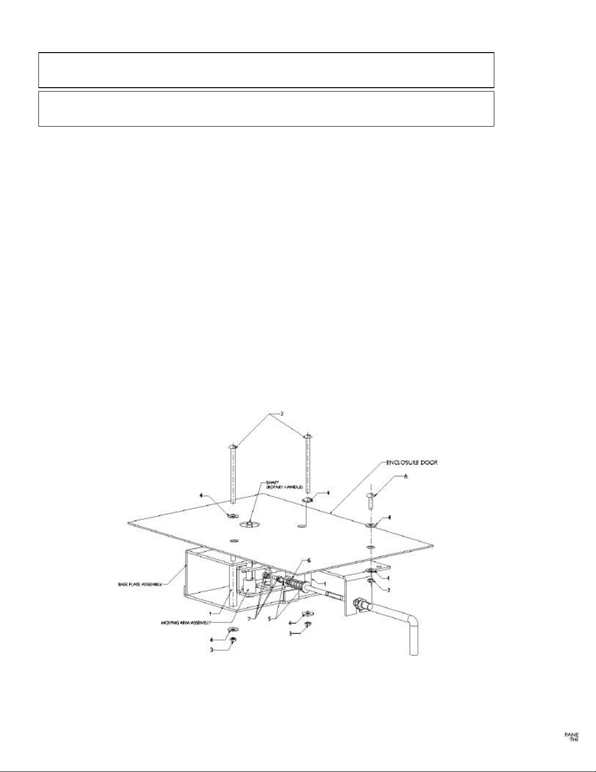
Cable Operated Interface Mechanism installation To Enclosure Door
1. Assemble GEPC rotary handle to the enclosure door through the h
handle instruction sheet.
2.
1, Figure 4, and Figure 5.
3. Assemble the GEPC rotary handle shaft one
shaft assembly and follow the GEPC rotary handle instruction sheet for more details on shaft assembly).
4.
the Figure 3.
5. Place and locate the spacer (item1), with base plate assembly holes of ¼ inch diameter & holes in enclosure door.
6. Install the cable-operated mechanism to the enclosure door with #12washers (item 4). Tighten the screws to 30-35 in-lb.
7. Refer Table 5 for hardware details.
Figure 1. Cable Operated Interface
Mechanism Installation to Enclosure Door.
The location of the enclosure face mounted SCRM
2
mechanism/handle with respect to the circuit breaker
mounting location is NOT fixed. The only requirements
Page 3

Table 2. Approximate Breaker Mounting Zone zone
To determine maximum mounting dimensions for
ing cables,
inch
cable maximum dimensions. (For example, add 12
inch cable
Figure 2. Shaft Length
Table 3. Shaft Length
Panel
Board
Thickness
(Inches) S/E ,S/F S/G S/K
0.075 3.0 3.0 3.0
0.125 3.0 3.0 3.0
0.1968 3.12 3.12 3.12
Shaft Length (Y)
Maximum Dimensions in Inches
Enclosure
Depth
8 13.5 4.0 15.0 25.5 16.0 27.0
10 13.0 5.0 14.8 25.0 17.0 26.8
12 12.8 6.0 14.5 24.8 17.0 26.5
16 10.5 4.5 14.2 22.5 16.5 26.2
18 8.5 3.5 12.6 20.5 15.5 24.6
20 — 0.5 10.0 22.0 15.0 24.0
24 — — — 19.5 14.0 22.0
* Maximum E dimension only if F = 4.5”.
60-inch through 120-inch-long operat
add the respective additional lengths to the 48-
E* F G E* F G
36” Cable 48” Cable
Figure 3. Drilling Diagram
Table 4. Drilling Diagram
X Y Z
SE & SF
SG 1.00 7.27 3.46
SK 0.54 9.02 4.60
0.82 7.13 3.06
inches to E, F, and G dimensions for 60length.)
3
Page 4

toute tension d’alimentation, et d’echarger les ressorts
d’armement.
Figure 4. Cable Installation – SE, SF, and SG.
Cable Installation-SE, SF, SG
WARNING: Before installing any accessories, turn the
breaker off, disconnect it from all voltage sources, and
discharge the closing springs.
A VERTISSEMENT: Avant d’installer tout accessoire,
mettre le disjoncteur en position OFF, le d’econnecter de
Use the following procedure to first install one end of the
operating cable to the interface mechanism, then the other
end to the breaker operating mechanism.
1. Slide a 7/16-20 hex nut onto the end of the cable with
the #10-32 x 7/8" thread. Install the nut onto the
threaded cable shank beyond the groove at the middle
of the shank. Install a 7/16" lock washer onto the hex
nut. Do not tighten.
2. Place the operating handle in the OFF position. Slide
a washer, a spring, a second washer, and thread two
#10-32 hex nuts on #10-32 x 7/8” thread. Ensure the
spring is between two washers. Set the nuts to 3/8
inches (SE, and SF) and 7/16 inches for SG onto the
thread end of the cable as shown in Figure 4. Rotate
the pivot bracket into position as shown in Figure 1 &
Figure 4. Insert the end of the cable through the pivot
bracket, thread two #10-32 hex nuts and tighten until
it is snug. Insert the groove of the cable into the slot on
the base plate. Tighten the 7/16" hex nut against the
cable operating mechanism base plate assembly until
it is snug.
3. Slide a 7/16-20 hex nut over the cable end with the
#10-32 x 3" thread. Install the nut onto the threaded
cable shank beyond the groove at the middle of the
shank. Install a 7/16" lock washer onto the hex nut.
Thread two #10-32 hex nuts approximately 23/4” onto
the threaded end of the cable. Rotate the pivot bracket
into position, as shown in Figure 4, and insert the end
of the cable through the pivot bracket. Insert the
groove of the cable into the slot on the base plate.
Tighten the 7/16-20 hex nut against the base plate
flange until snug. With the breaker in the OFF
position, move the #10-32 hex nut up on the cable
shaft against the pivot bracket. Note the position of the
pivot bracket in Figure 4.
4. Verify that the power to the circuit breaker has been
turned off. Move the operating handle on the circuit
breaker to the ON position. Place the spring over the
cable end. Thread the spring retainer onto the end of
the cable and tighten to the installed height of 17/16".
Do not over tighten the retainer.
5. Move the operating handle ON and then OFF. If the
breaker does not turn ON, then, with the handle in the
OFF position, adjust the #10-32 hex nut toward the
pivot bracket until the breaker turns ON.
6. Trip the circuit breaker by pushing the TRIP button.
Move the operating handle to the OFF/RESET
position, then to ON. If the breaker reset, lock both
#10-32 hex nuts against the pivot bracket. If the
breaker does not reset, adjust the # 10-32 hex nut away
from the pivot bracket until the breaker resets.
4
Page 5

cable shank beyond the groove at the middle of the
shank. Install a 5/8” lock washer onto the hex nut.
28” hex nuts approximately 2 ¾”
onto the threaded end of the cable. Rotate the pivot
cket into position, as shown in Figure 5, and insert
the end of the cable through the pivot bracket. Insert
the groove of the cable into the slot on the base plate.
18” hex nut against the base plate
n the off
28” hex nut upon the cable
shaft against the pivot bracket. Note the position of
rcuit
breaker to the ON position. Place the spring over the
cable end. Thread the spring retainer onto the end of
the cable and tighten to the installed height of 3
Breaker does not turn ON, then, with the handle in
28” hex nut toward
From the pivot bracket until the breaker resets.
toute
d’armement.
Figure 5. Cable Installation- SK.
Cable Installation -SK
WARNING: Before installing any accessories, turn the
breaker off, disconnect it from all voltage sources, and
discharge the closing springs.
A VERTISSEMENT: Avant d’installer tout accessoire,
mettre le disjonctur en position OFF, le d’econnecter de
tension d’alimentation, et d’echarger les ressorts
Use the following procedure to first install one end of the
operating cable to the interface mechanism, then the other
end to the breaker operating mechanism.
1. Slide a 5/8-18” hex nut onto the end of the cable with
the #1/4-28 x 1” thread. Install the nut onto the
threaded cable shank beyond the groove at the middle
of the shank. Install a 5/8” lock washer onto the hex
nut. Do not tighten.
2. Place the operating handle in the OFF position. Slide a
washer, a spring, a second washer, and thread two #1/428 hex nuts on #1/4-28 x 1” thread. Ensure the spring
in between the two washers. Set the nuts to 7/16 inches
onto the threaded end of the cable as shown in figure 5.
Rotate the pivot bracket into position as shown in
Figure 1 & Figure 5. Insert the end of the cable through
the pivot bracket, thread two #1/4-28 nuts, and tighten
until it is snug. Insert the groove of the cable into the
slot on the base plate. Tighten the 5/8-18" hex nut
against the cable operating mechanism base plate
assembly until it is snug.
3. Slide a 5/8-18” hex nut over the cable end with the
#1/4-28” thread. Install the nut onto the threaded
Thread two #1/4bra
Tighten the 5/8flange until snug. With the breaker i
position, move the #1/4-
the pivot bracket in Figure 5.
4. Verify that the power to the circuit breaker has been
Turned off. Move the operating handle on the ci
5/16”. Do not over tighten the retainer.
5. Move the operating handle ON and then OFF. If the
the OFF position, adjust the #1/4-
the pivot bracket until the breaker turns ON.
6. Trip the circuit breaker by pushing the TRIP button
Move the operating handle to the OFF/RESET
Position, then to ON. If the breaker reset, lock both
#1/4-28” hex nuts against the pivot bracket. If the
Breaker does not reset, adjust the # ¼-28 hex nut away
5
Page 6

6
E
CATALOGU
NO.
SRCM1EF
SRCM1G
S.NO. PART NO. NAME OF THE PART QTY/ASSY. Breaker
1 10087146P1 Steel pipe 2
2 N66P19056B #12-24 x 3 ½” Steel Screws 2
3 N210P19B6 # 12-24 Nut 3
4 N402P10B6 Washer, Steel Plate 6
5 N402P40B6 Washer 2
6 10086816P1 Compression Spring 1
7
8 N37P19012B6 #12-24 x 3/4” Steel Screw 1
1 10087146P2 Steel pipe 2
2 N66P19056B #12-24 x 3 ½” Steel Screws 2
3 N210P19B6 #12-24 Nut 3
4 N402P10B6 Washer, Steel Plate 6
5 N402P40B6 Washer 2
6 10086816P1 Compression Spring 1
7 10087374P1 #10-32 Hex Nut (Cable) 4
8 N37P19012B6 #12-24 x 3/4” Steel Screw 1
1 10087146P2 Steel pipe 2
2 N66P19056B 12-24 x 3 ½” Steel Screws 2
Table 5. Hardware Details
SE150/ SF250
10087374P1 #10-32 Hex Nut (Cable) 4
SG600
3 N210P19B6 #12-24 Nut 3
SRCM1K
These instructions do not cover all details or variations in equipment nor do they provide for every possible
contingency that may be met in connection with installation, operation, or maintenance. Should further
information be desired or should particular problems arise that are not covered sufficiently for the purchaser’s purposes, the matter should be referred to the GE Company.
g
4 N402P10B6 Washer, Steel Plate 6
5 N402P41B6 Washer 2
6 10086816P2 Compression Spring 1
7 10087374P2 Hex Thin Jam Nut (Cable) 4
8 N37P19012B6 #12-24 x 3/4” Steel Screw 1
SK1200
GE Industrial Systems
General Electric Company
41 Woodford Ave., Plainville, CT 06062
DEH-40467 R02 0198© 2001 General Electric Company
 Loading...